US4900643A - Lead acid bipolar battery plate and method of making the same - Google Patents
Lead acid bipolar battery plate and method of making the same Download PDFInfo
- Publication number
- US4900643A US4900643A US07/179,068 US17906888A US4900643A US 4900643 A US4900643 A US 4900643A US 17906888 A US17906888 A US 17906888A US 4900643 A US4900643 A US 4900643A
- Authority
- US
- United States
- Prior art keywords
- substrate
- metallic
- grid
- plate
- conductive
- Prior art date
- Legal status (The legal status is an assumption and is not a legal conclusion. Google has not performed a legal analysis and makes no representation as to the accuracy of the status listed.)
- Expired - Lifetime
Links
Images
Classifications
-
- H—ELECTRICITY
- H01—ELECTRIC ELEMENTS
- H01M—PROCESSES OR MEANS, e.g. BATTERIES, FOR THE DIRECT CONVERSION OF CHEMICAL ENERGY INTO ELECTRICAL ENERGY
- H01M10/00—Secondary cells; Manufacture thereof
- H01M10/06—Lead-acid accumulators
- H01M10/18—Lead-acid accumulators with bipolar electrodes
-
- H—ELECTRICITY
- H01—ELECTRIC ELEMENTS
- H01M—PROCESSES OR MEANS, e.g. BATTERIES, FOR THE DIRECT CONVERSION OF CHEMICAL ENERGY INTO ELECTRICAL ENERGY
- H01M4/00—Electrodes
- H01M4/02—Electrodes composed of, or comprising, active material
-
- H—ELECTRICITY
- H01—ELECTRIC ELEMENTS
- H01M—PROCESSES OR MEANS, e.g. BATTERIES, FOR THE DIRECT CONVERSION OF CHEMICAL ENERGY INTO ELECTRICAL ENERGY
- H01M4/00—Electrodes
- H01M4/02—Electrodes composed of, or comprising, active material
- H01M4/14—Electrodes for lead-acid accumulators
-
- H—ELECTRICITY
- H01—ELECTRIC ELEMENTS
- H01M—PROCESSES OR MEANS, e.g. BATTERIES, FOR THE DIRECT CONVERSION OF CHEMICAL ENERGY INTO ELECTRICAL ENERGY
- H01M4/00—Electrodes
- H01M4/02—Electrodes composed of, or comprising, active material
- H01M4/64—Carriers or collectors
-
- Y—GENERAL TAGGING OF NEW TECHNOLOGICAL DEVELOPMENTS; GENERAL TAGGING OF CROSS-SECTIONAL TECHNOLOGIES SPANNING OVER SEVERAL SECTIONS OF THE IPC; TECHNICAL SUBJECTS COVERED BY FORMER USPC CROSS-REFERENCE ART COLLECTIONS [XRACs] AND DIGESTS
- Y02—TECHNOLOGIES OR APPLICATIONS FOR MITIGATION OR ADAPTATION AGAINST CLIMATE CHANGE
- Y02E—REDUCTION OF GREENHOUSE GAS [GHG] EMISSIONS, RELATED TO ENERGY GENERATION, TRANSMISSION OR DISTRIBUTION
- Y02E60/00—Enabling technologies; Technologies with a potential or indirect contribution to GHG emissions mitigation
- Y02E60/10—Energy storage using batteries
-
- Y—GENERAL TAGGING OF NEW TECHNOLOGICAL DEVELOPMENTS; GENERAL TAGGING OF CROSS-SECTIONAL TECHNOLOGIES SPANNING OVER SEVERAL SECTIONS OF THE IPC; TECHNICAL SUBJECTS COVERED BY FORMER USPC CROSS-REFERENCE ART COLLECTIONS [XRACs] AND DIGESTS
- Y10—TECHNICAL SUBJECTS COVERED BY FORMER USPC
- Y10T—TECHNICAL SUBJECTS COVERED BY FORMER US CLASSIFICATION
- Y10T29/00—Metal working
- Y10T29/10—Battery-grid making
Definitions
- This invention relates to a bipolar battery plate and more particularly relates to bipolar batteries of the lead acid type and a method of making the same.
- the bipolar battery has shown increasing promise for use in applications where a high rate discharge performance is required such as in the starting, lighting and ignition (SLI applications) of automobiles.
- the traditional lead acid batteries generally employed suffer from the characteristic ohmic resistance provided by the electrode grid, grid lug, electrode current strap, and intercell connection. Large initial drops in voltage during high rate discharge are caused by the high current densities in such components. Additionally, the components increase the battery weight considerably, an unwanted feature today with the advent of light weight automobiles.
- Bipolar batteries because of the elimination of the components above, offer considerable advantages and have often been considered as possible replacements for traditional monopolar batteries in SLI applications.
- a bipolar battery is one that has plates with positive and negative active materials adhered to respective opposite sides of the plates.
- the function of the bipolar plate is to allow the current to pass from one electrode to another through a conductive substrate. This eliminates the need for grid lugs, current straps and intercell connections.
- the available cross-sectional area for conductivity is greatly increased. Additionally, the bipolar plates can be tightly stacked against each other with suitable electrolyte present, thus occupying less space.
- the bipolar plate of the present invention significantly reduces many of the aforementioned problems by providing a folded metallic mesh which encloses the sides and top of a conductive plastic substrate and is partially embedded within the side surfaces thereof.
- the division of the large surface area of the substrate into smaller discrete areas and the increased total surface area offered by the combined mesh-substrate dramatically enhances the adhesion of the active material thereto.
- the continuous mesh going from one side of the plate to the other provides increased conductivity without sacrificing the reduced weight provided by the conductive substrate.
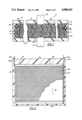
- FIG. 1 is a top sectional view of the interior of a battery employing bipolar plates in accordance with the present invention
- FIG. 2 is a side view of a single bipolar plate with the grid material exposed in accordance with the present invention.
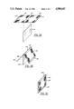
- FIGS. 3A-3C represent a schematic view of a method of fabricating a bipolar plate in accordance with the present invention.
- FIG. 1 depicts a battery 10 having a generally rectangular shape in section and comprising a plurality of stacked bipolar plates 12 sandwiched between two end blocks 36 and 37.
- Each plate 12 except for end plates 12a and 12b, have a substrate 14 with positive active material 18 and negative active material 16 adhered to the sides thereof.
- Each face of plate 12 abuts a separator 20 which serves to immobilize a liquid electrolyte that interacts electrochemically with the active materials 16 and 18 on the plate faces.
- the ends of substrate 14 are secured to a rectangularly-shaped frame 22 such that the entire plate 12 and frame 22 can be handled as a unit.
- each end of substrates 14 have a greater width that the adjacent portion thereof and fits within a complimentary channels of the frame 22 located along the midpoint thereof.
- the frame has a cross-sectional width greater than that of substrates 14, such that when the frames 22 and accompanying plates 12 are stacked and alternated with separators 20 slightly under pressure, each frame 22 is in a closely abutting relationship with an adjacent frame and encloses the plates 12 within.
- the grid and active material terminates short of each end of the substrate providing a space 23 defined by the interior wall 22a of frame 22, separator 20 and substrate 14.
- Each frame 22 may be formed with a pair of spaced surface grooves 25a, 27a in each major surface of frame 22 extending from the top of frame 22 terminating into channels 25b, 27b.
- Channel 27b as shown in FIG. 2 extends the entire length of frame 22.
- the grooves and channels on the abutting frame surfaces mate to form internal passageways extending from the mouth thereof to space 23.
- channel 25b communicates with space 23 near the top of frame 22 while channel 27b communicates with space 23 near the bottom thereof.
- Frame 22 may be formed with a pair of slots along the two facing interior surfaces of the frame 22 from the top thereof. The substrates may then fit within the slots in a tongue and slot arrangement.
- frame 22 being comprised of an inert non-conductive material may be injection molded about the sides of substrates 14. This technique immobilizes substrate 14 against movement within the slots.
- electrolyte may be added by forcing the electrolyte under pressure through groove 27b and applying a vacuum to groove 25a. A predetermined volume of electrolyte is then forced into space 23 and into the separator 20 partially filling the interstices therein.
- the opening to grooves 27a, 27b can be sealed off as desired, one alternative being the use of extensions from the battery casing top (not shown) which provides a fluid tight seal against extensions 25, 27.
- terminal plate 12a which is at one end of battery 10 has no active material layer and includes a conductive plate 30 extending from positive terminal 28.
- the outward facing surface of the terminal plate 12b has no active material and includes a conductive plate 34 extending from negative terminal 32.
- End blocks 36 and 37 enclose plates 30 and 34 and have openings permitting terminals 28 and 32 to extend through the openings which then may be sealed in any known manner.
- FIG. 2 where it may be seen that a portion of the active material has been eliminated in order to clearly portray a metallic sheet partially in the form of grid 38 on the surface of substrate 12.
- a grid 38 of metallic material is shown adhered to the surface of substrate 14, breaking the surface area of substrate 12 up into to discrete areas 40 having a diamond shape.
- Grid 38 terminates at, but is integral to, the metallic sheet forming fold 42 which is folded over the top of substrate 14.
- a second grid 38 extends from fold 42 on the opposite side thereof and is adhered to the opposite surface of substrate 12, similarly dividing the surface into a discrete surface areas.
- the material comprising the substrate 14 must necessarily be conductive and amenable to convenient fabrication and ultimate consolidation with the metallic grid. While various plastic materials impregnated with conductive filler are suitable, such as, for example, polyvinyledenefloride, tetrafloroethylene, polyethylene and polysulfone, it has been found that carbon-filled polypropylene provides the suitable characteristics needed. The percentage of carbon necessary for appropriate conductivity yet maintaining suitable substrate integrity and compatibility with the embedding of the mesh has been determined to be in the range of 12-25% by weight with 16-20% by weight being preferred.
- the material forming the separator can be any of various fibrous or interconnected void volume materials having an affinity, i.e. high heat of wettability for the liquid electrolyte.
- One function of the separator in a closed battery, involving a starved electrolyte system such as the bipolar battery of this type, is to immobilize the electrolyte within the battery and to permit transfer therethrough of gas generated during charging from one electrode.
- a material such as AGM or dexter glass mat which tends to permit movement of generated gas molecules along the glass fibers and through the interstices not occupied by electrolyte.
- a shelf or mud collector 44 may be appropriately formed into frame 22 below the area to which grid 38 is secured. Additionally, the internal space defined by the abutment of adjacent collectors 44 may serve as a reservoir for any electrolyte not immobilized by the separators.
- the metallic grid material employed can be any metallic material which has the characteristics necessary to form the desired functions such as, for example, compatibility with the substrate and proper electrochemical and conductive performance.
- Metallic materials such as lead, lead based alloys, and lead clad copper materials have all been found to perform satisfactorily.
- Other materials which may be used are titanium, tantalum, and zirconium.
- bipolar battery conductive substrates An important aspect of bipolar battery conductive substrates is to ensure that substrate material not only serves as a conductor but provides a suitable base material for the proper adherence of the active materials. As discussed before, poor adherence of active materials to the underlying substrate may result in the break up of the active material caused by the changes in active material volume during battery operation. Large gas pockets can form behind the active material which pulls the active material away from the substrate reducing available conductivity paths. Large pieces may also fall off exposing the substrate to the corrosive effects of the electrolytes and undesirable gas generation.
- the use of a metallic grid, however, which is embedded in the substrate substantially reduces the bubbling or blistering of the active material since the available surface area of the substrate is broken into discrete areas. Additionally, adherence of the active material is promoted due to the uneven surface and better adhesion characteristics of the combined substrate and metallic grid surface.
- substrates of conductive plastic generally plastic composition having a percentage of conductive material, form a thin insulative layer at the surface thereof during manufacturing.
- the thin low conductive layer is broken up or bypassed as the embedded portion of the grid is contact with the more conductive, underlying regions of the substrate.
- bipolar batteries using metallic foils adhered to a conductive substrates suffer not only from the infirmity of having to ensure that the adhesive itself is conductive but the presence of the less conductive layer lying adjacent the substrate surface.
- the fabrication of the bipolar plate in accordance with the present invention is best discussed by referring to FIGS. 3A-3B.
- the metallic grid which, by way of example, could be a lead based composition can be formed through any of several techniques, but a preferred way is through the use of rotary expander such as described in U.S. Pat. No. 4,291,443 issued on Sept. 29, 1981 to Cominco Ltd. of Vancouver, Canada which describes an apparatus forming metallic grids out of metal sheet.
- the grid is desireably formed in a continuous web having a grid portion of a predetermined width and length separated by a solid foil portion.
- the sheets can then be divided along the center line of every other foil portion to form a pair of grids 46 separated by a solid foil portion 48 in FIG. 3A and end portions 49.
- the connected pair of grids 46 are positioned adjacent a substrate 50 with the center line of foil 48 abutting the top edge thereof and thereafter folded over to place each grid 46 in contact with substrate 50.
- the width of grid 46 is slightly less than the width of substrate 50.
- pressure is applied against both surfaces and grids 46 of the substrate and heated.
- the grid 46 is partially embedded into the substrate, then a plastic base frame is molded about the edges of the substrate and sealed thereto by thermal welding or other sealing techniques.
- the appropriate pressure and heat to be applied is a function of the material composition of the conductive plastic substrate and metallic foil. However, it is necessary to ensure that the pressure and heat are sufficient to embed the metallic grid the desired distance within the substrate to provide sufficient operating integrity, i.e. no separation of the grid and underlying substrate during battery use, without weakening or destroying the substrate. To that extent, it has been found that heat can be employed which is sufficient to raise the temperature of the grid so as to cause melting of the substrate at the metallic grid substrate interface without causing the remainder of the substrate material to flow. The greater heat conductivity of the metallic grid is ideally suited for accomplishing this.
- the depth of embedment of the metallic grid required is again a function of the affinity between the materials comprising the substrate and metallic grid, it is preferred that the grid be embedded about one-half or more of the diameter of the individual metallic wires making up the grid.
- the mesh size of the grid and the diameter of the individual wires is dependent upon the appropriate balance between the desired weight of the plate and conductivity required among other variables.
- a carbon-filled polypropylene substrate of about 16% by weight carbon and a metallic grid of lead it has been found advantageous to use a diamond shaped grid with a wire diameter of 0.015 inches. While the grid dimension itself is largely a matter of preference, it has been found desirable to use a long diagonal axis of about 0.27 inches and a short diagonal axis of about 0.19 inches. It should be clear, however, that other combinations of mesh sizes and wire diameters could be employed depending upon the application required and materials employed.
- the metallic grid is actually folded over the top of the substrate, the adherence of the grid to the substrate is promoted since the substrate itself is supporting the metallic grid. Separation of the grid from the substrate is substantially minimized. Additionally, the continuous nature of the grid from one side to the other of the substrate supplies still another conductive path in addition to that provided by the substrate. This is particularly advantageous since the use of a conductive plastic instead of metallic plate sacrifices conductivity for a reduction in weight.
- the combined conductive plastic substrate and embedded folded metallic grid provides the needed light weight plate design without sacrificing conductivity.
Abstract
Description
Claims (19)
Priority Applications (1)
| Application Number | Priority Date | Filing Date | Title |
|---|---|---|---|
| US07/179,068 US4900643A (en) | 1988-04-08 | 1988-04-08 | Lead acid bipolar battery plate and method of making the same |
Applications Claiming Priority (1)
| Application Number | Priority Date | Filing Date | Title |
|---|---|---|---|
| US07/179,068 US4900643A (en) | 1988-04-08 | 1988-04-08 | Lead acid bipolar battery plate and method of making the same |
Publications (1)
| Publication Number | Publication Date |
|---|---|
| US4900643A true US4900643A (en) | 1990-02-13 |
Family
ID=22655109
Family Applications (1)
| Application Number | Title | Priority Date | Filing Date |
|---|---|---|---|
| US07/179,068 Expired - Lifetime US4900643A (en) | 1988-04-08 | 1988-04-08 | Lead acid bipolar battery plate and method of making the same |
Country Status (1)
| Country | Link |
|---|---|
| US (1) | US4900643A (en) |
Cited By (66)
| Publication number | Priority date | Publication date | Assignee | Title |
|---|---|---|---|---|
| US5068160A (en) * | 1990-04-17 | 1991-11-26 | Ensci, Inc. | Bipolar plate battery |
| US5114807A (en) * | 1990-04-30 | 1992-05-19 | California Institute Of Technology | Lightweight bipolar storage battery |
| US5156932A (en) * | 1991-05-02 | 1992-10-20 | Globe-Union, Inc. | Simple optimized lead-acid battery |
| EP0552126A2 (en) * | 1992-01-16 | 1993-07-21 | Globe-Union Inc. | Internally folded expanded metal electrode for battery construction |
| US5232797A (en) * | 1990-04-17 | 1993-08-03 | Ensci, Inc. | Bipolar plate battery |
| US5288566A (en) * | 1990-11-21 | 1994-02-22 | Edison Termoelettricc S.P.A. | Sealed lead acid bipolar battery |
| US5334464A (en) * | 1991-07-22 | 1994-08-02 | Bipolar Power Corporation | Lightweight battery plates |
| US5439756A (en) * | 1994-02-28 | 1995-08-08 | Motorola, Inc. | Electrical energy storage device and method of charging and discharging same |
| US5441824A (en) * | 1994-12-23 | 1995-08-15 | Aerovironment, Inc. | Quasi-bipolar battery requiring no casing |
| US5508131A (en) * | 1994-04-07 | 1996-04-16 | Globe-Union Inc. | Injection molded battery containment for bipolar batteries |
| EP0726610A1 (en) | 1994-12-30 | 1996-08-14 | EDISON TERMOELETTRICA S.p.A. | A method of sealing and packaging a lead acid bipolar battery by using polyolefin based materials, and relevant product |
| EP0726611A1 (en) | 1994-12-30 | 1996-08-14 | EDISON TERMOELETTRICA S.p.A. | A method of forming a lead acid bipolar battery electrode having a peripheral sealing frame and relevant product |
| US5587250A (en) * | 1995-09-27 | 1996-12-24 | Motorola, Inc. | Hybrid energy storage system |
| US5643696A (en) * | 1991-07-22 | 1997-07-01 | Bipolar Power Corporation | Battery plates with lightweight cores |
| US5645959A (en) * | 1992-08-20 | 1997-07-08 | Bipolar Power Corporation | Battery plates with self-passivating iron cores and mixed acid electrolyte |
| US5670266A (en) * | 1996-10-28 | 1997-09-23 | Motorola, Inc. | Hybrid energy storage system |
| US5688615A (en) * | 1995-11-03 | 1997-11-18 | Globe-Union, Inc. | Bipolar battery and method of making same |
| US5744697A (en) * | 1995-08-16 | 1998-04-28 | J And N Associates, Inc. | Gas sensor with conductive housing portions |
| US5800946A (en) * | 1996-12-06 | 1998-09-01 | Grosvenor; Victor L. | Bipolar lead-acid battery plates |
| WO1998040920A2 (en) * | 1997-03-12 | 1998-09-17 | Nederlandse Organisatie Voor Toegepast-Natuurwetenschappelijk Onderzoek Tno | Method for manufacturing a bipolar plate |
| US5849426A (en) * | 1996-09-20 | 1998-12-15 | Motorola, Inc. | Hybrid energy storage system |
| US5993494A (en) * | 1997-07-25 | 1999-11-30 | Gnb Technologies, Inc. | Method of manufacturing modular components for a bipolar battery and the resulting bipolar battery |
| US6020082A (en) * | 1998-02-19 | 2000-02-01 | Summit Microelectronics, Inc. | Integrated battery identification system and method for determination of battery type and voltage level operability |
| US6087812A (en) * | 1997-06-13 | 2000-07-11 | Motorola, Inc. | Independent dual-switch system for extending battery life under transient loads |
| US6103413A (en) * | 1998-05-21 | 2000-08-15 | The Dow Chemical Company | Bipolar plates for electrochemical cells |
| US6117585A (en) * | 1997-07-25 | 2000-09-12 | Motorola, Inc. | Hybrid energy storage device |
| US6146780A (en) * | 1997-01-24 | 2000-11-14 | Lynntech, Inc. | Bipolar separator plates for electrochemical cell stacks |
| US6232010B1 (en) | 1999-05-08 | 2001-05-15 | Lynn Tech Power Systems, Ltd. | Unitized barrier and flow control device for electrochemical reactors |
| US6305214B1 (en) | 1999-08-26 | 2001-10-23 | Sensor Tek, Llc | Gas sensor and methods of forming a gas sensor assembly |
| US20030232234A1 (en) * | 2002-05-31 | 2003-12-18 | Cisar Alan J. | Electrochemical cell and bipolar assembly for an electrochemical cell |
| US20040121238A1 (en) * | 2002-12-23 | 2004-06-24 | Kelley Kurtis C. | Battery having carbon foam current collector |
| US20040121237A1 (en) * | 2002-12-20 | 2004-06-24 | Kelley Kurtis C | Composite material and current collector for battery |
| US20040161653A1 (en) * | 2002-12-04 | 2004-08-19 | Craig Andrews | Very thin, light bipolar plates |
| US20040191632A1 (en) * | 2002-06-28 | 2004-09-30 | Kelley Kurtis Chad | Battery including carbon foam current collectors |
| US20050207969A1 (en) * | 2004-03-19 | 2005-09-22 | Ges Technologies, S. De R.L. De C.V. | Production of tetrabasic lead sulfate from solid state reactions for the preparation of active plates to be used in lead-acid batteries |
| US20060024583A1 (en) * | 2004-07-15 | 2006-02-02 | Board Of Control Of Michigan Technological University | Nickel hydroxide impregnated carbon foam electrodes for rechargeable nickel batteries |
| US20060045725A1 (en) * | 2004-06-09 | 2006-03-02 | Vb Autobatterie Gmbh & Co. Kgaa | Device and method for stacking and transporting plates |
| US20060216595A1 (en) * | 2005-03-22 | 2006-09-28 | Holliday Rex W | Battery assembly having improved lug profile |
| WO2006114605A1 (en) * | 2005-04-27 | 2006-11-02 | Atraverda Limited | Electrode and manufacturing methods |
| US7150846B2 (en) * | 2002-12-23 | 2006-12-19 | Basf Aktiengesellschaft | Bipolar plate and method of fabricating it |
| US20070003830A1 (en) * | 2004-01-21 | 2007-01-04 | Varta Automotive Systems Gmbh | Prismatic rechargeable battery and method for producing such a battery |
| US20070269592A1 (en) * | 2003-10-21 | 2007-11-22 | Johnson Controls Technology Company | Battery Paste Material and Method |
| WO2008059529A1 (en) * | 2006-11-15 | 2008-05-22 | Luminous Power Technologies Pvt Ltd | Bipolar battery |
| US20090130549A1 (en) * | 2007-11-20 | 2009-05-21 | Firefly Energy Inc. | Lead acid battery including a two-layer carbon foam current collector |
| US20090233175A1 (en) * | 2005-03-31 | 2009-09-17 | Kelley Kurtis C | Current Carrier for an Energy Storage Device |
| US20100183920A1 (en) * | 2009-01-21 | 2010-07-22 | Advanced Battery Concepts, LLC | Bipolar battery assembly |
| US8597817B2 (en) | 2011-09-09 | 2013-12-03 | East Penn Manufacturing Co., Inc. | Bipolar battery and plate |
| US9531031B2 (en) | 2011-10-24 | 2016-12-27 | Advanced Battery Concepts, LLC | Bipolar battery assembly |
| US9634319B2 (en) | 2011-09-09 | 2017-04-25 | East Penn Manufacturing Co., Inc. | Bipolar battery and plate |
| US9685677B2 (en) | 2011-10-24 | 2017-06-20 | Advanced Battery Concepts, LLC | Bipolar battery assembly |
| US9941546B2 (en) | 2011-09-09 | 2018-04-10 | East Penn Manufacturing Co., Inc. | Bipolar battery and plate |
| US10141598B2 (en) | 2011-10-24 | 2018-11-27 | Advanced Battery Concepts, LLC | Reinforced bipolar battery assembly |
| JP2019079614A (en) * | 2017-10-20 | 2019-05-23 | 株式会社豊田自動織機 | Power storage module, and method for manufacturing power storage module |
| US10312549B2 (en) * | 2011-09-09 | 2019-06-04 | East Penn Manufacturing Co. | Bipolar battery and plate |
| JP2019102165A (en) * | 2017-11-29 | 2019-06-24 | 株式会社豊田自動織機 | Manufacturing method of power storage module, and power storage module |
| JP2019114456A (en) * | 2017-12-25 | 2019-07-11 | 株式会社豊田自動織機 | Power storage module and method for manufacturing power storage module |
| JP2019121448A (en) * | 2017-12-28 | 2019-07-22 | 株式会社豊田自動織機 | Power-storage module and manufacturing method thereof |
| JP2019121449A (en) * | 2017-12-28 | 2019-07-22 | 株式会社豊田自動織機 | Power-storage module and manufacturing method thereof |
| JP2019121447A (en) * | 2017-12-28 | 2019-07-22 | 株式会社豊田自動織機 | Power-storage module and manufacturing method thereof |
| JP2019121450A (en) * | 2017-12-28 | 2019-07-22 | 株式会社豊田自動織機 | Power-storage module and manufacturing method thereof |
| US10446822B2 (en) | 2011-10-24 | 2019-10-15 | Advanced Battery Concepts, LLC | Bipolar battery assembly |
| US10615393B2 (en) | 2011-10-24 | 2020-04-07 | Advanced Battery Concepts, LLC | Bipolar battery assembly |
| US10693193B2 (en) | 2018-06-13 | 2020-06-23 | Trojan Battery Company, Llc | Bi-plate grids for batteries, and single process to cast the same |
| US10804540B2 (en) | 2015-05-01 | 2020-10-13 | Pivotal Battery Corp | Bipolar plate and method of making and using same |
| GB2585897A (en) * | 2019-07-22 | 2021-01-27 | The Ultimate Battery Company Ltd | Bipolar battery |
| US11888106B2 (en) | 2019-05-24 | 2024-01-30 | Advanced Battery Concepts, LLC | Battery assembly with integrated edge seal and methods of forming the seal |
Citations (4)
| Publication number | Priority date | Publication date | Assignee | Title |
|---|---|---|---|---|
| US3170820A (en) * | 1963-03-19 | 1965-02-23 | Union Carbide Corp | Method of making duplex electrodes for high rate primary batteries |
| US4098967A (en) * | 1973-05-23 | 1978-07-04 | Gould Inc. | Electrochemical system using conductive plastic |
| US4237205A (en) * | 1979-10-22 | 1980-12-02 | General Motors Corporation | Pocket grid for alkaline battery plates |
| US4275130A (en) * | 1979-09-27 | 1981-06-23 | California Institute Of Technology | Bipolar battery construction |
-
1988
- 1988-04-08 US US07/179,068 patent/US4900643A/en not_active Expired - Lifetime
Patent Citations (4)
| Publication number | Priority date | Publication date | Assignee | Title |
|---|---|---|---|---|
| US3170820A (en) * | 1963-03-19 | 1965-02-23 | Union Carbide Corp | Method of making duplex electrodes for high rate primary batteries |
| US4098967A (en) * | 1973-05-23 | 1978-07-04 | Gould Inc. | Electrochemical system using conductive plastic |
| US4275130A (en) * | 1979-09-27 | 1981-06-23 | California Institute Of Technology | Bipolar battery construction |
| US4237205A (en) * | 1979-10-22 | 1980-12-02 | General Motors Corporation | Pocket grid for alkaline battery plates |
Cited By (105)
| Publication number | Priority date | Publication date | Assignee | Title |
|---|---|---|---|---|
| US5232797A (en) * | 1990-04-17 | 1993-08-03 | Ensci, Inc. | Bipolar plate battery |
| US5068160A (en) * | 1990-04-17 | 1991-11-26 | Ensci, Inc. | Bipolar plate battery |
| US5114807A (en) * | 1990-04-30 | 1992-05-19 | California Institute Of Technology | Lightweight bipolar storage battery |
| US5288566A (en) * | 1990-11-21 | 1994-02-22 | Edison Termoelettricc S.P.A. | Sealed lead acid bipolar battery |
| US5156932A (en) * | 1991-05-02 | 1992-10-20 | Globe-Union, Inc. | Simple optimized lead-acid battery |
| US5334464A (en) * | 1991-07-22 | 1994-08-02 | Bipolar Power Corporation | Lightweight battery plates |
| US5643696A (en) * | 1991-07-22 | 1997-07-01 | Bipolar Power Corporation | Battery plates with lightweight cores |
| EP0552126A2 (en) * | 1992-01-16 | 1993-07-21 | Globe-Union Inc. | Internally folded expanded metal electrode for battery construction |
| EP0552126A3 (en) * | 1992-01-16 | 1993-09-15 | Globe-Union Inc. | Internally folded expanded metal electrode for battery construction |
| US5645959A (en) * | 1992-08-20 | 1997-07-08 | Bipolar Power Corporation | Battery plates with self-passivating iron cores and mixed acid electrolyte |
| US5439756A (en) * | 1994-02-28 | 1995-08-08 | Motorola, Inc. | Electrical energy storage device and method of charging and discharging same |
| WO1995023437A1 (en) * | 1994-02-28 | 1995-08-31 | Motorola Inc. | Electrical energy storage device and method of charging and discharging same |
| US5508131A (en) * | 1994-04-07 | 1996-04-16 | Globe-Union Inc. | Injection molded battery containment for bipolar batteries |
| US5441824A (en) * | 1994-12-23 | 1995-08-15 | Aerovironment, Inc. | Quasi-bipolar battery requiring no casing |
| EP0726610A1 (en) | 1994-12-30 | 1996-08-14 | EDISON TERMOELETTRICA S.p.A. | A method of sealing and packaging a lead acid bipolar battery by using polyolefin based materials, and relevant product |
| EP0726611A1 (en) | 1994-12-30 | 1996-08-14 | EDISON TERMOELETTRICA S.p.A. | A method of forming a lead acid bipolar battery electrode having a peripheral sealing frame and relevant product |
| US5667537A (en) * | 1994-12-30 | 1997-09-16 | Edison Termoelettrica, S.P.A. | Forming a lead acid bipolar battery electrode having a peripheral sealing frame and relevant product |
| US5729891A (en) * | 1994-12-30 | 1998-03-24 | Edison Termoelettrica S.P.A. | Method of sealing and packaging a lead acid bipolar battery by using polyolefin based materials |
| US5777208A (en) * | 1995-08-16 | 1998-07-07 | J And N Associates, Inc. | Gas sensor with pressurized seal |
| US5827948A (en) * | 1995-08-16 | 1998-10-27 | J And N Associates, Inc. | Gas sensor with liquid-tight seal |
| US5987965A (en) * | 1995-08-16 | 1999-11-23 | J And N Associates, Inc. | Gas sensor with conductive housing portions |
| US5744697A (en) * | 1995-08-16 | 1998-04-28 | J And N Associates, Inc. | Gas sensor with conductive housing portions |
| US5587250A (en) * | 1995-09-27 | 1996-12-24 | Motorola, Inc. | Hybrid energy storage system |
| US5688615A (en) * | 1995-11-03 | 1997-11-18 | Globe-Union, Inc. | Bipolar battery and method of making same |
| US5849426A (en) * | 1996-09-20 | 1998-12-15 | Motorola, Inc. | Hybrid energy storage system |
| US5670266A (en) * | 1996-10-28 | 1997-09-23 | Motorola, Inc. | Hybrid energy storage system |
| US6077623A (en) * | 1996-12-06 | 2000-06-20 | Grosvenor; Victor L. | Bipolar lead-acid battery plates and method of making same |
| US5800946A (en) * | 1996-12-06 | 1998-09-01 | Grosvenor; Victor L. | Bipolar lead-acid battery plates |
| US6638657B1 (en) | 1997-01-24 | 2003-10-28 | Lynntech Power Systems, Ltd. | Fluid cooled bipolar plate |
| US6146780A (en) * | 1997-01-24 | 2000-11-14 | Lynntech, Inc. | Bipolar separator plates for electrochemical cell stacks |
| WO1998040920A3 (en) * | 1997-03-12 | 1998-11-26 | Tno | Method for manufacturing a bipolar plate |
| WO1998040920A2 (en) * | 1997-03-12 | 1998-09-17 | Nederlandse Organisatie Voor Toegepast-Natuurwetenschappelijk Onderzoek Tno | Method for manufacturing a bipolar plate |
| US6087812A (en) * | 1997-06-13 | 2000-07-11 | Motorola, Inc. | Independent dual-switch system for extending battery life under transient loads |
| US5993494A (en) * | 1997-07-25 | 1999-11-30 | Gnb Technologies, Inc. | Method of manufacturing modular components for a bipolar battery and the resulting bipolar battery |
| US6117585A (en) * | 1997-07-25 | 2000-09-12 | Motorola, Inc. | Hybrid energy storage device |
| US6020082A (en) * | 1998-02-19 | 2000-02-01 | Summit Microelectronics, Inc. | Integrated battery identification system and method for determination of battery type and voltage level operability |
| US6103413A (en) * | 1998-05-21 | 2000-08-15 | The Dow Chemical Company | Bipolar plates for electrochemical cells |
| US6232010B1 (en) | 1999-05-08 | 2001-05-15 | Lynn Tech Power Systems, Ltd. | Unitized barrier and flow control device for electrochemical reactors |
| US20030124411A1 (en) * | 1999-05-08 | 2003-07-03 | Lynntech, Inc. | Unitized barrier and flow control device for electrochemical reactors |
| US6991869B2 (en) | 1999-05-08 | 2006-01-31 | Lynntech Power Systems, Ltd. | Unitized barrier and flow control device for electrochemical reactors |
| US6305214B1 (en) | 1999-08-26 | 2001-10-23 | Sensor Tek, Llc | Gas sensor and methods of forming a gas sensor assembly |
| US20030232234A1 (en) * | 2002-05-31 | 2003-12-18 | Cisar Alan J. | Electrochemical cell and bipolar assembly for an electrochemical cell |
| US20040191632A1 (en) * | 2002-06-28 | 2004-09-30 | Kelley Kurtis Chad | Battery including carbon foam current collectors |
| US20050191555A1 (en) * | 2002-06-28 | 2005-09-01 | Firefly Energy Inc. | Battery including carbon foam current collectors |
| US6979513B2 (en) | 2002-06-28 | 2005-12-27 | Firefly Energy Inc. | Battery including carbon foam current collectors |
| US20040161653A1 (en) * | 2002-12-04 | 2004-08-19 | Craig Andrews | Very thin, light bipolar plates |
| US7736783B2 (en) | 2002-12-04 | 2010-06-15 | Lynntech, Inc. | Very thin, light bipolar plates |
| US20040121237A1 (en) * | 2002-12-20 | 2004-06-24 | Kelley Kurtis C | Composite material and current collector for battery |
| US7033703B2 (en) | 2002-12-20 | 2006-04-25 | Firefly Energy, Inc. | Composite material and current collector for battery |
| US20040121238A1 (en) * | 2002-12-23 | 2004-06-24 | Kelley Kurtis C. | Battery having carbon foam current collector |
| US7341806B2 (en) | 2002-12-23 | 2008-03-11 | Caterpillar Inc. | Battery having carbon foam current collector |
| US7150846B2 (en) * | 2002-12-23 | 2006-12-19 | Basf Aktiengesellschaft | Bipolar plate and method of fabricating it |
| US7517370B2 (en) | 2003-10-21 | 2009-04-14 | Johnson Controls Technology Company | Battery paste material and method |
| US20080087868A1 (en) * | 2003-10-21 | 2008-04-17 | Johnson Controls Technology Company | Battery paste material and method |
| US20070269592A1 (en) * | 2003-10-21 | 2007-11-22 | Johnson Controls Technology Company | Battery Paste Material and Method |
| US7790310B2 (en) | 2004-01-21 | 2010-09-07 | Varta Automotive Systems Gmbh | Prismatic rechargeable battery |
| US7867292B2 (en) | 2004-01-21 | 2011-01-11 | Varta Automotive Systems Gmbh | Prismatic rechargeable battery and method for producing such a battery |
| US20080134494A1 (en) * | 2004-01-21 | 2008-06-12 | Varta Automotive Systems Gmbh | Prismatic rechargeable battery and method for producing such a battery |
| US20070003830A1 (en) * | 2004-01-21 | 2007-01-04 | Varta Automotive Systems Gmbh | Prismatic rechargeable battery and method for producing such a battery |
| US7011805B2 (en) | 2004-03-19 | 2006-03-14 | Ges Technologies Ip Gmbh | Production of tetrabasic lead sulfate from solid state reactions for the preparation of active plates to be used in lead-acid batteries |
| US7550131B2 (en) | 2004-03-19 | 2009-06-23 | Ges Technologies Ip Gmbh | Production of tetrabasic lead sulfate from solid state reactions for the preparation of active plates to be used in lead-acid batteries |
| US20050207969A1 (en) * | 2004-03-19 | 2005-09-22 | Ges Technologies, S. De R.L. De C.V. | Production of tetrabasic lead sulfate from solid state reactions for the preparation of active plates to be used in lead-acid batteries |
| US7309478B2 (en) | 2004-03-19 | 2007-12-18 | Ges Technologies Ip Gmbh | Production of tetrabasic lead sulfate from solid state reactions for the preparation of active plates to be used in lead-acid batteries |
| US7582384B2 (en) | 2004-03-19 | 2009-09-01 | Ges Technologies Ip Gmbh | Production of tetrabasic lead sulfate from solid state reactions for the preparation of active plates to be used in lead-acid batteries |
| US20080181841A1 (en) * | 2004-03-19 | 2008-07-31 | Ges Technologies Ip Gmbh | Production of tetrabasic lead sulfate from solid state reactions for the preparation of active plates to be used in lead-acid batteries |
| US20060088465A1 (en) * | 2004-03-19 | 2006-04-27 | Ges Technologies Ip Gmbh | Production of tetrabasic lead sulfate from solid state reactions for the preparation of active plates to be used in lead-acid batteries |
| US7459140B2 (en) | 2004-03-19 | 2008-12-02 | Ges Technologies Ip Gmbh | Production of tetrabasic lead sulfate from solid state reactions for the preparation of active plates to be used in lead-acid batteries |
| US20060045725A1 (en) * | 2004-06-09 | 2006-03-02 | Vb Autobatterie Gmbh & Co. Kgaa | Device and method for stacking and transporting plates |
| US20060024583A1 (en) * | 2004-07-15 | 2006-02-02 | Board Of Control Of Michigan Technological University | Nickel hydroxide impregnated carbon foam electrodes for rechargeable nickel batteries |
| US20060216595A1 (en) * | 2005-03-22 | 2006-09-28 | Holliday Rex W | Battery assembly having improved lug profile |
| US20090233175A1 (en) * | 2005-03-31 | 2009-09-17 | Kelley Kurtis C | Current Carrier for an Energy Storage Device |
| US20080193850A1 (en) * | 2005-04-27 | 2008-08-14 | Atraverda Limited | Electrode and Manufacturing Methods |
| US8119290B2 (en) | 2005-04-27 | 2012-02-21 | Atraverda Limited | Electrode and manufacturing methods |
| WO2006114605A1 (en) * | 2005-04-27 | 2006-11-02 | Atraverda Limited | Electrode and manufacturing methods |
| US20100062335A1 (en) * | 2006-11-15 | 2010-03-11 | Luminous Power Technologies Pvt Ltd | Bipolar battery |
| WO2008059529A1 (en) * | 2006-11-15 | 2008-05-22 | Luminous Power Technologies Pvt Ltd | Bipolar battery |
| US20090130549A1 (en) * | 2007-11-20 | 2009-05-21 | Firefly Energy Inc. | Lead acid battery including a two-layer carbon foam current collector |
| US8399134B2 (en) | 2007-11-20 | 2013-03-19 | Firefly Energy, Inc. | Lead acid battery including a two-layer carbon foam current collector |
| US20100183920A1 (en) * | 2009-01-21 | 2010-07-22 | Advanced Battery Concepts, LLC | Bipolar battery assembly |
| US8357469B2 (en) | 2009-01-21 | 2013-01-22 | Advanced Battery Concepts, LLC | Bipolar battery assembly |
| US9941546B2 (en) | 2011-09-09 | 2018-04-10 | East Penn Manufacturing Co., Inc. | Bipolar battery and plate |
| US8597817B2 (en) | 2011-09-09 | 2013-12-03 | East Penn Manufacturing Co., Inc. | Bipolar battery and plate |
| US10312549B2 (en) * | 2011-09-09 | 2019-06-04 | East Penn Manufacturing Co. | Bipolar battery and plate |
| US9634319B2 (en) | 2011-09-09 | 2017-04-25 | East Penn Manufacturing Co., Inc. | Bipolar battery and plate |
| US9553329B2 (en) | 2011-10-24 | 2017-01-24 | Advanced Battery Concepts, LLC | Bipolar battery assembly |
| US10446822B2 (en) | 2011-10-24 | 2019-10-15 | Advanced Battery Concepts, LLC | Bipolar battery assembly |
| US9859543B2 (en) | 2011-10-24 | 2018-01-02 | Advanced Battery Concepts, LLC | Bipolar battery assembly |
| US9685677B2 (en) | 2011-10-24 | 2017-06-20 | Advanced Battery Concepts, LLC | Bipolar battery assembly |
| US10141598B2 (en) | 2011-10-24 | 2018-11-27 | Advanced Battery Concepts, LLC | Reinforced bipolar battery assembly |
| US9825336B2 (en) | 2011-10-24 | 2017-11-21 | Advanced Battery Concepts, LLC | Bipolar battery assembly |
| US9531031B2 (en) | 2011-10-24 | 2016-12-27 | Advanced Battery Concepts, LLC | Bipolar battery assembly |
| US10615393B2 (en) | 2011-10-24 | 2020-04-07 | Advanced Battery Concepts, LLC | Bipolar battery assembly |
| US10804540B2 (en) | 2015-05-01 | 2020-10-13 | Pivotal Battery Corp | Bipolar plate and method of making and using same |
| JP2019079614A (en) * | 2017-10-20 | 2019-05-23 | 株式会社豊田自動織機 | Power storage module, and method for manufacturing power storage module |
| JP2019102165A (en) * | 2017-11-29 | 2019-06-24 | 株式会社豊田自動織機 | Manufacturing method of power storage module, and power storage module |
| JP7056102B2 (en) | 2017-11-29 | 2022-04-19 | 株式会社豊田自動織機 | Manufacturing method of power storage module and power storage module |
| JP2019114456A (en) * | 2017-12-25 | 2019-07-11 | 株式会社豊田自動織機 | Power storage module and method for manufacturing power storage module |
| JP2019121448A (en) * | 2017-12-28 | 2019-07-22 | 株式会社豊田自動織機 | Power-storage module and manufacturing method thereof |
| JP2019121449A (en) * | 2017-12-28 | 2019-07-22 | 株式会社豊田自動織機 | Power-storage module and manufacturing method thereof |
| JP2019121447A (en) * | 2017-12-28 | 2019-07-22 | 株式会社豊田自動織機 | Power-storage module and manufacturing method thereof |
| JP2019121450A (en) * | 2017-12-28 | 2019-07-22 | 株式会社豊田自動織機 | Power-storage module and manufacturing method thereof |
| US10693193B2 (en) | 2018-06-13 | 2020-06-23 | Trojan Battery Company, Llc | Bi-plate grids for batteries, and single process to cast the same |
| US11888106B2 (en) | 2019-05-24 | 2024-01-30 | Advanced Battery Concepts, LLC | Battery assembly with integrated edge seal and methods of forming the seal |
| GB2585897A (en) * | 2019-07-22 | 2021-01-27 | The Ultimate Battery Company Ltd | Bipolar battery |
| GB2585897B (en) * | 2019-07-22 | 2023-09-06 | The Ultimate Battery Company Ltd | Bipolar battery |
Similar Documents
| Publication | Publication Date | Title |
|---|---|---|
| US4900643A (en) | Lead acid bipolar battery plate and method of making the same | |
| KR100274559B1 (en) | Packaging for an electrochemical device and device using same | |
| KR0136040B1 (en) | Bipolar battery and assembling method | |
| US5470679A (en) | Method of assembling a bipolar lead-acid battery and the resulting bipolar battery | |
| US4505992A (en) | Integral gas seal for fuel cell gas distribution assemblies and method of fabrication | |
| US5916709A (en) | Bipolar lead-acid battery | |
| US5508131A (en) | Injection molded battery containment for bipolar batteries | |
| DK2518790T3 (en) | Stacked structures for electrochemical batteries | |
| US4855193A (en) | Bipolar fuel cell | |
| US4732637A (en) | Method of fabricating an integral gas seal for fuel cell gas distribution assemblies | |
| KR100894409B1 (en) | Secondary Battery Having Improved Safety by Fixing Separator to Battery Case | |
| EP0188873B1 (en) | Lightweight bipolar metal-gas battery | |
| EP1686639A1 (en) | Lithium ion polymer secondary battery and gelatinous polymer electrolyte for sheet battery | |
| CA2342980A1 (en) | Supercapacitor structure and method of making same | |
| JPH0748453B2 (en) | Electric double layer capacitor | |
| JPH0422867B2 (en) | ||
| JP2008541353A (en) | Bipolar electrochemical secondary battery | |
| GB2294803A (en) | High-temperature cell having curved solid electrolyte separator and flexible anode cover to accommodate volume changes during charging/discharging | |
| US4507857A (en) | Electrochemical cell | |
| EP0630063A1 (en) | Bipolar battery electrode and method | |
| US7186478B2 (en) | Electrochemical device | |
| US5225292A (en) | Internally folded expanded metal electrode for battery construction | |
| US6017649A (en) | Multiple step fuel cell seal | |
| KR20080003473A (en) | Secondary battery having improved sealing property at heat-melted portion of case | |
| JPH0982306A (en) | Lead-acid battery and manufacture thereof |
Legal Events
| Date | Code | Title | Description |
|---|---|---|---|
| AS | Assignment |
Owner name: GLOBE-UNION INC., P.O. BOX 591, MILWAUKEE, WI 5320 Free format text: ASSIGNMENT OF ASSIGNORS INTEREST.;ASSIGNORS:ESKRA, MICHAEL D.;DELANEY, WILLIAM C.;BOWEN, GERALD K.;REEL/FRAME:004905/0340 Effective date: 19880606 Owner name: GLOBE-UNION INC.,WISCONSIN Free format text: ASSIGNMENT OF ASSIGNORS INTEREST;ASSIGNORS:ESKRA, MICHAEL D.;DELANEY, WILLIAM C.;BOWEN, GERALD K.;REEL/FRAME:004905/0340 Effective date: 19880606 |
|
| STCF | Information on status: patent grant |
Free format text: PATENTED CASE |
|
| FEPP | Fee payment procedure |
Free format text: PAYOR NUMBER ASSIGNED (ORIGINAL EVENT CODE: ASPN); ENTITY STATUS OF PATENT OWNER: LARGE ENTITY |
|
| FPAY | Fee payment |
Year of fee payment: 4 |
|
| REMI | Maintenance fee reminder mailed | ||
| FEPP | Fee payment procedure |
Free format text: PAYER NUMBER DE-ASSIGNED (ORIGINAL EVENT CODE: RMPN); ENTITY STATUS OF PATENT OWNER: LARGE ENTITY Free format text: PAYOR NUMBER ASSIGNED (ORIGINAL EVENT CODE: ASPN); ENTITY STATUS OF PATENT OWNER: LARGE ENTITY |
|
| FPAY | Fee payment |
Year of fee payment: 8 |
|
| SULP | Surcharge for late payment | ||
| AS | Assignment |
Owner name: JOHNSON CONTROLS TECHNOLOGY COMPANY, MICHIGAN Free format text: ASSIGNMENT OF ASSIGNORS INTEREST;ASSIGNOR:GLOBE UNION INC.;REEL/FRAME:009289/0165 Effective date: 19980618 |
|
| FPAY | Fee payment |
Year of fee payment: 12 |