US4900108A - Self-fixturing cabinet corner member - Google Patents
Self-fixturing cabinet corner member Download PDFInfo
- Publication number
- US4900108A US4900108A US07/368,620 US36862089A US4900108A US 4900108 A US4900108 A US 4900108A US 36862089 A US36862089 A US 36862089A US 4900108 A US4900108 A US 4900108A
- Authority
- US
- United States
- Prior art keywords
- legs
- sides
- corner
- pair
- corner member
- Prior art date
- Legal status (The legal status is an assumption and is not a legal conclusion. Google has not performed a legal analysis and makes no representation as to the accuracy of the status listed.)
- Expired - Lifetime
Links
- 238000004378 air conditioning Methods 0.000 claims abstract description 18
- 239000000463 material Substances 0.000 claims description 12
- 238000010438 heat treatment Methods 0.000 claims description 7
- 239000002184 metal Substances 0.000 claims description 7
- 229910000831 Steel Inorganic materials 0.000 claims 1
- 239000010959 steel Substances 0.000 claims 1
- 238000000034 method Methods 0.000 abstract description 13
- 238000004519 manufacturing process Methods 0.000 description 10
- 238000005452 bending Methods 0.000 description 1
- 238000005266 casting Methods 0.000 description 1
- 230000002860 competitive effect Effects 0.000 description 1
- 238000001125 extrusion Methods 0.000 description 1
- 230000003993 interaction Effects 0.000 description 1
- 230000008447 perception Effects 0.000 description 1
- 230000001681 protective effect Effects 0.000 description 1
- 239000002699 waste material Substances 0.000 description 1
Images

Classifications
-
- F—MECHANICAL ENGINEERING; LIGHTING; HEATING; WEAPONS; BLASTING
- F24—HEATING; RANGES; VENTILATING
- F24F—AIR-CONDITIONING; AIR-HUMIDIFICATION; VENTILATION; USE OF AIR CURRENTS FOR SCREENING
- F24F13/00—Details common to, or for air-conditioning, air-humidification, ventilation or use of air currents for screening
- F24F13/20—Casings or covers
-
- A—HUMAN NECESSITIES
- A47—FURNITURE; DOMESTIC ARTICLES OR APPLIANCES; COFFEE MILLS; SPICE MILLS; SUCTION CLEANERS IN GENERAL
- A47B—TABLES; DESKS; OFFICE FURNITURE; CABINETS; DRAWERS; GENERAL DETAILS OF FURNITURE
- A47B47/00—Cabinets, racks or shelf units, characterised by features related to dismountability or building-up from elements
- A47B47/0008—Three-dimensional corner connectors, the legs thereof being received within hollow, elongated frame members
-
- A—HUMAN NECESSITIES
- A47—FURNITURE; DOMESTIC ARTICLES OR APPLIANCES; COFFEE MILLS; SPICE MILLS; SUCTION CLEANERS IN GENERAL
- A47B—TABLES; DESKS; OFFICE FURNITURE; CABINETS; DRAWERS; GENERAL DETAILS OF FURNITURE
- A47B2220/00—General furniture construction, e.g. fittings
- A47B2220/11—Tripod parts
-
- F—MECHANICAL ENGINEERING; LIGHTING; HEATING; WEAPONS; BLASTING
- F16—ENGINEERING ELEMENTS AND UNITS; GENERAL MEASURES FOR PRODUCING AND MAINTAINING EFFECTIVE FUNCTIONING OF MACHINES OR INSTALLATIONS; THERMAL INSULATION IN GENERAL
- F16B—DEVICES FOR FASTENING OR SECURING CONSTRUCTIONAL ELEMENTS OR MACHINE PARTS TOGETHER, e.g. NAILS, BOLTS, CIRCLIPS, CLAMPS, CLIPS OR WEDGES; JOINTS OR JOINTING
- F16B12/00—Jointing of furniture or the like, e.g. hidden from exterior
- F16B12/44—Leg joints; Corner joints
- F16B2012/446—Leg joints; Corner joints with three-dimensional corner element, the legs thereof being inserted in hollow frame members
-
- Y—GENERAL TAGGING OF NEW TECHNOLOGICAL DEVELOPMENTS; GENERAL TAGGING OF CROSS-SECTIONAL TECHNOLOGIES SPANNING OVER SEVERAL SECTIONS OF THE IPC; TECHNICAL SUBJECTS COVERED BY FORMER USPC CROSS-REFERENCE ART COLLECTIONS [XRACs] AND DIGESTS
- Y10—TECHNICAL SUBJECTS COVERED BY FORMER USPC
- Y10T—TECHNICAL SUBJECTS COVERED BY FORMER US CLASSIFICATION
- Y10T403/00—Joints and connections
- Y10T403/55—Member ends joined by inserted section
- Y10T403/555—Angle section
Definitions
- the present invention relates to a structural component for a cabinet-like enclosure. More specifically, the present invention relates to a corner member for the framework of a cabinet of the type which typically encloses and supports heating, ventilating and air conditioning equipment on the rooftops and at the sides of buildings.
- heating, ventilating and air conditioning equipment cabinets are utilitarian in nature, functioning primarily to shelter and support active components of a heating, ventilating and air conditioning system, they are often conspicuous on rooftops and at the sides of buildings and therefore affect the perception of individuals with respect to the aesthetics of the building.
- Such cabinets and their frameworks must provide a rigid, protective and strong structure for the purpose of properly mounting and sheltering equipment such as heat exchanger coils, fans, compressors filters and the like while providing sizeable side openings through which large volumes of air are directed.
- the cabinets must also support weighty accessories which extend outwardly from and are supported by the exterior of the cabinet structure.
- Such cabinet structures which may weigh many thousands of pounds, must also be capable of being lifted to great heights while maintaining the structural integrity necessary to prevent the misalignment or damage of the cabinet itself or of the active air conditioning system components which they house.
- a cabinet corner member having three pair of attachment legs each pair of which extends in a different direction from one side of a three-sided corner portion.
- Each one of the three pair of legs is preferably in a plane parallel to but offset from the plane of the one of the three sides of the corner portion from which it extends.
- each one of each of the three pair of legs cooperates with and extends in the same direction as one of the legs of another of the three pair of legs to create a combined 90° attachment portion for other cabinet structural members.
- the two legged 90° attachment portions extend from the corner portion and accommodate the attachment of square, rectangular, angle, channel or other types of structural members.
- each of the six legs extending from the corner portion is a discrete leg and because the corner portion is itself somewhat flexible due to the existence of an open seam between two of its three sides, the corner member of the present invention is extremely flexible and is self-fixturing during the cabinet assembly process yet the end result is a cabinet which is both strong and rigid.
- corner member permits and promotes the rapid and efficient assembly of an air conditioning cabinet in a manner which accommodates slight misalignments and minimizes the need to force-fit or otherwise stress members of the structure in order to finish the cabinet assembly process.
- Cabinets employing the corner member of the present invention are, in their finished state, extremely strong and rigid. Further, the corner member of the present invention is capable of being fabricated from a single piece of material and therefore, in addition to minimizing assembly labor costs due to its self-fixturing nature, it minimizes cabinet material costs as it is economical to produce. Finally, because of the offset of the legs extending from the corner portion of the corner member a framework is created which contributes to the development of an aesthetically pleasing cabinet.
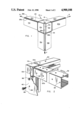
- FIG. 1 is a perspective view of the corner member of the present invention.
- FIG. 2 is an exploded perspective view of the corner of an air conditioning cabinet constructed with the corner member of the present invention.
- FIG. 3 is a side view of the corner member of the present invention better illustrating the offset of the legs from the sides of the corner portion from which they extend as well as the interaction of the corner member with other cabinet structural components.
- FIG. 4 illustrates the unitary blank piece of material from which the corner member of the present invention is fabricated.
- corner member 10 includes a three sided corner portion 12 having sides 12a, 12b and 12c. Extending from corner portion 12 are legs 14a and 16a. Legs 18b and 20b extend from side 12b while legs 22c and 24c extend from side 12c.
- legs 14a and 16a comprise a first pair of legs characterized by their extension, at right angles from and in the same plane as each other, from a single first side 12a of corner portion 12.
- legs 18b and 20b comprise a pair of coplanar legs extending, at right angles from each other, from single corner portion side 12b.
- legs 22c and 24c are characterized as a pair of coplanar legs which extend from single side 12c of corner portion 12 at right angles to each other.
- Legs 14a, 16a, 18b, 20b, 22c and 24c can also be grouped in discrete other pairs which are characterized by their extension, in the same direction and in planes which are at 90° angles with respect to each other, from different ones of the single sides 12a, 12b and 12c of the corner portion. That is, legs 14a and 24c can be characterized as a pair of 90° attachment legs which extend in a first direction X from corner portion 12 while legs 16a and 18b are a pair of attachment legs which extend in a direction Y from corner portion 12 and legs 20b and 22c are a pair of attachment legs which extend from corner portion 12 in a third direction Z.
- each of the first mentioned pair of legs (which are attached to and extend from a common side of corner portion 12) are coplanar and at right angles with each to other. These first mentioned pairs of legs, each of which extends from a common side, lie in a plane parallel to the plane of the side of corner portion 12 from which they extend.
- each of the second mentioned pairs (categorized as attachment legs extending in a common direction from different side of corner portion 12) are disposed in planes which are nominally at 90° angles with respect to each other and that each leg of an attachment pair has an edge, such as, for example, edges 26a of leg 14a and 28c of leg 24c, which is adjacent but physically separated from an edge of the other leg in that attachment pair to form an open seam 29 therebetween.
- corner member 10 is adapted to be connected to a structural member such as channel 32.
- channel 32 is but one example of the numerous types of structural elements which can be accommodated by and attached to corner member 10.
- structural members that are square, rectangular, angled or the like in cross section can be attached to corner member 10 so long as they have a surface or surfaces which are dimensioned to abut at least one, but preferably two, legs of the corner member.
- corner member 10 is, as a whole, three dimensionally flexible in the X, Y and Z directions illustrated in FIG. 1. This flexibility facilitates rapid cabinet assembly by making the corner member self-fixturing with respect to the attachment, one each to a different one of the three 90° attachment pairs of legs, of structural members, such as channels 32, to it.
- Corner member 10 This self-fixturing feature of corner member 10 is extremely important in the manufacturing process in that it eliminates the need to physically bend, twist or otherwise force components of the cabinet such as other framework members or its generally planar sheet metal sides 40 into compliance with each other in a manner which can distort one or more of the cabinet components and the waste of labor and materials. Corner member 10 therefore promotes ease and efficiency of the cabinet fabrication process while at the same time minimizing the likelihood that a cabinet component will be distorted in that process by tolerating and accommodating the slight misalignments which are, essentially inherent in the fabrication of structures of this size and weight.
- legs 22c and 20b of member 10 are disposed and become ensconced within channel 32 during the assembly process. That is, the legs of member 10 are dimensioned to fit snugly against and within the interior walls of the channel member.
- Channel member 32 is simply and quickly pushed onto an over legs 20b and 22c until end 42 of channel member 32 abuts the radius 44 of member 10 which is created by the offset of the legs from the sides from which they extend.
- offset 30 is preferably dimensioned so as to be the same as the thickness of the material from which channel 32 is fabricated, the outward facing sides of channel member 32 will be coplanar with the side of corner portion 12 with which they abut.
- the result is an essentially smooth and near-seamless cabinet framework that cleanly and efficiently accommodates the attachment of the cabinet side panels which will typically be fabricated from a thinner gauge of flat sheet metal.
- corner member 10 is efficiently and economically fabricated from a unitary piece of material, such as a heavier gauge sheet metal.
- FIG. 4 illustrates each of legs 14a, 16a. 18b, 20b, 22c and 24c as well as sides 12a, 12b and 12c of the corner member in their preformed shape.
- edges 26a and 26b of legs 14a and 24c are illustrated as are edges 36a and 36b of sides 12a and 12b which cooperate to form the open seam between two of the three sides of corner portion 12.
- FIG. 4 additionally illustrates that in order to finally form corner member 10 a relatively simple and efficient stamping and bending process can be employed.
- Lines 46 and 48 represent lines at which 90° bends in the material must be accomplished.
- Lines 50. 52, 54, 56, 58 and 60 represent the locations at which radii 44 are formed in a stamping process that creates the offsets 30 of each leg from the side face of corner portion 12 from which it extends.
- attachment holes 62 in corner member 10, attachment holes 64 in exemplary structural member channel 32 and attachment holes 66 in typical cabinet side member 40 can be pre-drilled and pre-located such that when channel member 32 is assembled onto a pair of attachment legs and when side 40 is placed thereover for attachment to the resulting cabinet framework, attachment holes 62, 64 and 66 all come into alignment so that corner member 10, channel 32 and side 40 are all capable of being rigidly attached to each other by a single fastener such as by sheet metal screw 68.
- corner member 10 in cooperation with other cabinet structural members such as channel 32 is extremely strong and rigid. This is particularly important with respect to those sides of an air conditioning cabinet which define large openings or from which heavy accessories hang. While the primary feature of corner member 10 is its self-fixturing nature which promotes ease and efficiency in cabinet assembly process and which accommodates slight misalignments, its ability to accommodate other structural members of varying cross sectional geometry, its relatively inexpensive cost of manufacture and the contribution it makes to an aesthetically pleasing final appearance in the finished cabinet product are likewise significant advantages.
- corner member of the present invention has been described in the context of an air conditioning cabinet application, it will be appreciated that it has general application in the fabrication of cabinets and enclosures for other purposes. It will also be appreciated that sides 12a 12b and 12c of corner member 10 need not necessarily be square but can be rectangular and of different dimensions one from the other. While the present invention has been described in the context of a preferred embodiment, it will also be appreciated that its breadth should not be construed or limited other than by the language of the claims which follow.
Abstract
Description
Claims (14)
Priority Applications (1)
| Application Number | Priority Date | Filing Date | Title |
|---|---|---|---|
| US07/368,620 US4900108A (en) | 1989-06-20 | 1989-06-20 | Self-fixturing cabinet corner member |
Applications Claiming Priority (1)
| Application Number | Priority Date | Filing Date | Title |
|---|---|---|---|
| US07/368,620 US4900108A (en) | 1989-06-20 | 1989-06-20 | Self-fixturing cabinet corner member |
Publications (1)
| Publication Number | Publication Date |
|---|---|
| US4900108A true US4900108A (en) | 1990-02-13 |
Family
ID=23452013
Family Applications (1)
| Application Number | Title | Priority Date | Filing Date |
|---|---|---|---|
| US07/368,620 Expired - Lifetime US4900108A (en) | 1989-06-20 | 1989-06-20 | Self-fixturing cabinet corner member |
Country Status (1)
| Country | Link |
|---|---|
| US (1) | US4900108A (en) |
Cited By (23)
| Publication number | Priority date | Publication date | Assignee | Title |
|---|---|---|---|---|
| US5806945A (en) * | 1995-09-22 | 1998-09-15 | Amco Engineering Co. | Modular enclosure and method |
| US6164460A (en) * | 1998-03-26 | 2000-12-26 | Rittal-Werk Rudolf Loh Gmbh & Co. Kg | Rack for a switchgear cabinet |
| US6205738B1 (en) * | 1999-03-29 | 2001-03-27 | Yang Fan Development Co., Ltd. | Frame for forming a housing of a group of air-handling units |
| US6260374B1 (en) | 2000-04-26 | 2001-07-17 | American Standard International Inc. | Easily installable field configurable air conditioning unit |
| WO2001051721A1 (en) | 2000-01-10 | 2001-07-19 | Torri S.P.A. | Modular joint for industrial metal structures |
| US20050034390A1 (en) * | 2003-08-14 | 2005-02-17 | York International Corporation | Raceway construction for an air handling unit |
| US20050084324A1 (en) * | 2003-08-14 | 2005-04-21 | York International Corporation | Corner cap member construction for an air handling unit |
| US20050188640A1 (en) * | 2004-02-26 | 2005-09-01 | Miller Lester D. | Quick frame construction system and method |
| US20090199746A1 (en) * | 2008-02-09 | 2009-08-13 | Martin R Horton | Table |
| US20110050052A1 (en) * | 2009-09-01 | 2011-03-03 | Emerson Network Power, Energy Systems, North America, Inc. | Telecommunications Enclosures |
| US20120024811A1 (en) * | 2010-07-28 | 2012-02-02 | Hon Hai Precision Industry Co., Ltd. | Rack frame assembly |
| US20120292278A1 (en) * | 2011-05-16 | 2012-11-22 | Middle Atlantic Products, Inc. | Rack Assembly |
| US20150111485A1 (en) * | 2013-10-23 | 2015-04-23 | Lg Electronics Inc. | Air handler and method for assembling an air handler |
| US9549482B2 (en) | 2014-09-05 | 2017-01-17 | Emerson Network Power, Energy Systems, North America, Inc. | Cabinet frame enclosures, frame members and corresponding methods |
| US9702615B1 (en) * | 2016-01-13 | 2017-07-11 | Electrolux Home Products, Inc. | Internal cabinet support structure |
| US9857094B2 (en) | 2013-10-23 | 2018-01-02 | Lg Electronics Inc. | Air handler and a fan module for an air handler |
| US9964330B2 (en) | 2013-10-23 | 2018-05-08 | Lg Electronics Inc. | Air handler |
| US10208892B1 (en) * | 2015-10-15 | 2019-02-19 | Jay G. Bianchini | Method and apparatus for creating a pre-fabricated kit for assembling and suspending a custom design frame for supporting a package in an elevated position |
| US20190117511A1 (en) * | 2017-10-20 | 2019-04-25 | Frantrice McMillan-Riley | Secure Medication Storage System and Method of Securely Storing Medication in Healthcare Facility |
| US10443885B2 (en) | 2013-10-23 | 2019-10-15 | Lg Electronics Inc. | Air handler having fan module and separation partition |
| DE102018128259A1 (en) * | 2018-11-12 | 2020-05-14 | Anja Stolzenberger | MOBILE BUILDING, IN PARTICULAR TINY HOUSE |
| US11118617B1 (en) * | 2018-04-30 | 2021-09-14 | Valley Design Enterprises Inc | Table leg attachment |
| US11346384B2 (en) * | 2019-07-12 | 2022-05-31 | Ralph Sloan Wilson, JR. | Three-axis ninety-degree triangular brace |
Citations (9)
| Publication number | Priority date | Publication date | Assignee | Title |
|---|---|---|---|---|
| BE620483A (en) * | ||||
| FR972215A (en) * | 1948-01-08 | 1951-01-26 | Metal cabinet with frames joined by corner joints | |
| US3304108A (en) * | 1963-12-18 | 1967-02-14 | Hamilton Cosco Inc | Tube construction |
| US3702211A (en) * | 1971-07-14 | 1972-11-07 | Carrier Corp | Frame for rooftop air conditioner |
| DE2129858A1 (en) * | 1971-06-16 | 1972-12-21 | Metallbau Bedarf Gmbh | Frame of windows and doors made of hollow profiles, the corners of which are reinforced by built-in angle pieces |
| US4691970A (en) * | 1985-04-12 | 1987-09-08 | Armando Neri | Dustproof cabinet, in particular for electrical equipment |
| US4747505A (en) * | 1986-08-28 | 1988-05-31 | American Standard Inc. | Unitized cabinet design |
| US4759196A (en) * | 1987-05-26 | 1988-07-26 | American Standard Inc. | Two-position cover for air handling equipment enclosure |
| US4776484A (en) * | 1986-08-28 | 1988-10-11 | American Standard Inc. | Unitized cabinet design |
-
1989
- 1989-06-20 US US07/368,620 patent/US4900108A/en not_active Expired - Lifetime
Patent Citations (9)
| Publication number | Priority date | Publication date | Assignee | Title |
|---|---|---|---|---|
| BE620483A (en) * | ||||
| FR972215A (en) * | 1948-01-08 | 1951-01-26 | Metal cabinet with frames joined by corner joints | |
| US3304108A (en) * | 1963-12-18 | 1967-02-14 | Hamilton Cosco Inc | Tube construction |
| DE2129858A1 (en) * | 1971-06-16 | 1972-12-21 | Metallbau Bedarf Gmbh | Frame of windows and doors made of hollow profiles, the corners of which are reinforced by built-in angle pieces |
| US3702211A (en) * | 1971-07-14 | 1972-11-07 | Carrier Corp | Frame for rooftop air conditioner |
| US4691970A (en) * | 1985-04-12 | 1987-09-08 | Armando Neri | Dustproof cabinet, in particular for electrical equipment |
| US4747505A (en) * | 1986-08-28 | 1988-05-31 | American Standard Inc. | Unitized cabinet design |
| US4776484A (en) * | 1986-08-28 | 1988-10-11 | American Standard Inc. | Unitized cabinet design |
| US4759196A (en) * | 1987-05-26 | 1988-07-26 | American Standard Inc. | Two-position cover for air handling equipment enclosure |
Cited By (32)
| Publication number | Priority date | Publication date | Assignee | Title |
|---|---|---|---|---|
| US5806945A (en) * | 1995-09-22 | 1998-09-15 | Amco Engineering Co. | Modular enclosure and method |
| US6164460A (en) * | 1998-03-26 | 2000-12-26 | Rittal-Werk Rudolf Loh Gmbh & Co. Kg | Rack for a switchgear cabinet |
| US6205738B1 (en) * | 1999-03-29 | 2001-03-27 | Yang Fan Development Co., Ltd. | Frame for forming a housing of a group of air-handling units |
| WO2001051721A1 (en) | 2000-01-10 | 2001-07-19 | Torri S.P.A. | Modular joint for industrial metal structures |
| US6260374B1 (en) | 2000-04-26 | 2001-07-17 | American Standard International Inc. | Easily installable field configurable air conditioning unit |
| US20050084324A1 (en) * | 2003-08-14 | 2005-04-21 | York International Corporation | Corner cap member construction for an air handling unit |
| US7334377B2 (en) | 2003-08-14 | 2008-02-26 | Johnson Controls Technology Company | Raceway construction for an air handing unit |
| US20050034390A1 (en) * | 2003-08-14 | 2005-02-17 | York International Corporation | Raceway construction for an air handling unit |
| US20050188640A1 (en) * | 2004-02-26 | 2005-09-01 | Miller Lester D. | Quick frame construction system and method |
| US20090199746A1 (en) * | 2008-02-09 | 2009-08-13 | Martin R Horton | Table |
| US8403431B2 (en) * | 2009-09-01 | 2013-03-26 | Emerson Network Power, Energy Systems, North America, Inc. | Telecommunications enclosures |
| US20110050052A1 (en) * | 2009-09-01 | 2011-03-03 | Emerson Network Power, Energy Systems, North America, Inc. | Telecommunications Enclosures |
| US20120024811A1 (en) * | 2010-07-28 | 2012-02-02 | Hon Hai Precision Industry Co., Ltd. | Rack frame assembly |
| US8292093B2 (en) * | 2010-07-28 | 2012-10-23 | Hon Hai Precision Industry Co., Ltd. | Rack frame assembly |
| US9155383B2 (en) * | 2011-05-16 | 2015-10-13 | Middle Atlantic Products, Inc. | Rack assembly |
| US20120292278A1 (en) * | 2011-05-16 | 2012-11-22 | Middle Atlantic Products, Inc. | Rack Assembly |
| US10443885B2 (en) | 2013-10-23 | 2019-10-15 | Lg Electronics Inc. | Air handler having fan module and separation partition |
| US9857093B2 (en) * | 2013-10-23 | 2018-01-02 | Lg Electronics Inc. | Air handler and method for assembling an air handler |
| US20150111485A1 (en) * | 2013-10-23 | 2015-04-23 | Lg Electronics Inc. | Air handler and method for assembling an air handler |
| US9857094B2 (en) | 2013-10-23 | 2018-01-02 | Lg Electronics Inc. | Air handler and a fan module for an air handler |
| US9964330B2 (en) | 2013-10-23 | 2018-05-08 | Lg Electronics Inc. | Air handler |
| US9549482B2 (en) | 2014-09-05 | 2017-01-17 | Emerson Network Power, Energy Systems, North America, Inc. | Cabinet frame enclosures, frame members and corresponding methods |
| US9596778B2 (en) | 2014-09-05 | 2017-03-14 | Emerson Network Power, Energy Systems, North America, Inc. | Cabinet frame enclosures, frame members and corresponding methods |
| US9622369B2 (en) | 2014-09-05 | 2017-04-11 | Emerson Network Power, Energy Systems, North America, Inc. | Cabinet frame enclosures, frame members and corresponding methods |
| US9578772B2 (en) | 2014-09-05 | 2017-02-21 | Emerson Network Power, Energy Systems, North America, Inc. | Cabinet frame enclosures, frame members and corresponding methods |
| US10208892B1 (en) * | 2015-10-15 | 2019-02-19 | Jay G. Bianchini | Method and apparatus for creating a pre-fabricated kit for assembling and suspending a custom design frame for supporting a package in an elevated position |
| US11054084B1 (en) | 2015-10-15 | 2021-07-06 | Jay G. Bianchini | Method and apparatus for creating a pre-fabricated kit for assembling and suspending a custom design frame for supporting a package in an elevated position |
| US9702615B1 (en) * | 2016-01-13 | 2017-07-11 | Electrolux Home Products, Inc. | Internal cabinet support structure |
| US20190117511A1 (en) * | 2017-10-20 | 2019-04-25 | Frantrice McMillan-Riley | Secure Medication Storage System and Method of Securely Storing Medication in Healthcare Facility |
| US11118617B1 (en) * | 2018-04-30 | 2021-09-14 | Valley Design Enterprises Inc | Table leg attachment |
| DE102018128259A1 (en) * | 2018-11-12 | 2020-05-14 | Anja Stolzenberger | MOBILE BUILDING, IN PARTICULAR TINY HOUSE |
| US11346384B2 (en) * | 2019-07-12 | 2022-05-31 | Ralph Sloan Wilson, JR. | Three-axis ninety-degree triangular brace |
Similar Documents
| Publication | Publication Date | Title |
|---|---|---|
| US4900108A (en) | Self-fixturing cabinet corner member | |
| JP2895239B2 (en) | Frame used for switch cabinet | |
| US4426120A (en) | Sectioned cabinet for room air conditioning unit | |
| US20160215997A1 (en) | Insulated panel assembly | |
| US11499743B1 (en) | Grille assembly | |
| JPH06109299A (en) | Ventilation hood with panel holder | |
| US3858995A (en) | Heating and ventilating enclosure module connection means | |
| CN215802596U (en) | Connection structure convenient to dismouting | |
| JPH0544660Y2 (en) | ||
| EP0266330A1 (en) | Ceiling panel suspension frame | |
| US3254929A (en) | Cabinet construction for air conditioning unit | |
| KR100804605B1 (en) | The installing structure of ceiling cassetteair-conditioner | |
| JPH0380647B2 (en) | ||
| JPH0875183A (en) | Air conditioner | |
| JP3139253B2 (en) | Outdoor unit case structure | |
| JP3005143U (en) | Protective net cover for outdoor unit | |
| JPH0434337Y2 (en) | ||
| US20090002944A1 (en) | Ventilating Exhaust Fan Housing | |
| JPS6015841Y2 (en) | panel mounting device | |
| JPH0322685Y2 (en) | ||
| JPS5853266B2 (en) | Outdoor casing of separate air conditioner | |
| JPH065533Y2 (en) | Connection structure of cover for air conditioning pipe, inner joint member for lid, and inner joint member for cover | |
| JPH0532919U (en) | Air conditioner housing | |
| JPH0440113Y2 (en) | ||
| JPH042622Y2 (en) |
Legal Events
| Date | Code | Title | Description |
|---|---|---|---|
| AS | Assignment |
Owner name: AMERICAN STANDARD INC., NEW YORK Free format text: ASSIGNMENT OF ASSIGNORS INTEREST.;ASSIGNOR:TISCHER, JAMES C.;REEL/FRAME:005095/0221 Effective date: 19890620 |
|
| STCF | Information on status: patent grant |
Free format text: PATENTED CASE |
|
| FPAY | Fee payment |
Year of fee payment: 4 |
|
| AS | Assignment |
Owner name: CHEMICAL BANK, AS COLLATERAL AGENT, NEW YORK Free format text: ASSIGNMENT OF ASSIGNORS INTEREST;ASSIGNOR:AMERICAN STANDARD INC.;REEL/FRAME:006566/0170 Effective date: 19930601 |
|
| FPAY | Fee payment |
Year of fee payment: 8 |
|
| AS | Assignment |
Owner name: AMERICAN STANDARD, INC., NEW JERSEY Free format text: RELEASE OF SECURITY INTEREST (RE-RECORD TO CORRECT DUPLICATES SUBMITTED BY CUSTOMER. THE NEW SCHEDULE CHANGES THE TOTAL NUMBER OF PROPERTY NUMBERS INVOLVED FROM 1133 TO 794. THIS RELEASE OF SECURITY INTEREST WAS PREVIOUSLY RECORDED AT REEL 8869, FRAME 0001.);ASSIGNOR:CHASE MANHATTAN BANK, THE (FORMERLY KNOWN AS CHEMICAL BANK);REEL/FRAME:009123/0300 Effective date: 19970801 |
|
| AS | Assignment |
Owner name: AMERICAN STANDARD, INC., NEW JERSEY Free format text: RELEASE OF SECURITY INTEREST;ASSIGNOR:CHASE MANHATTAN BANK, THE (FORMERLY KNOWN AS CHEMICAL BANK);REEL/FRAME:008869/0001 Effective date: 19970801 |
|
| FEPP | Fee payment procedure |
Free format text: PAYOR NUMBER ASSIGNED (ORIGINAL EVENT CODE: ASPN); ENTITY STATUS OF PATENT OWNER: LARGE ENTITY |
|
| FPAY | Fee payment |
Year of fee payment: 12 |
|
| AS | Assignment |
Owner name: IDEAL STANDARD GLOBAL LTD., UNITED KINGDOM Free format text: ASSIGNMENT OF ASSIGNORS INTEREST;ASSIGNOR:AMERICAN STANDARD INC.;REEL/FRAME:022092/0592 Effective date: 20071031 |