US4867699A - Connector with checking device - Google Patents
Connector with checking device Download PDFInfo
- Publication number
- US4867699A US4867699A US07/316,737 US31673789A US4867699A US 4867699 A US4867699 A US 4867699A US 31673789 A US31673789 A US 31673789A US 4867699 A US4867699 A US 4867699A
- Authority
- US
- United States
- Prior art keywords
- connector
- connectors
- latching
- mated
- projection
- Prior art date
- Legal status (The legal status is an assumption and is not a legal conclusion. Google has not performed a legal analysis and makes no representation as to the accuracy of the status listed.)
- Expired - Fee Related
Links
- 230000013011 mating Effects 0.000 claims description 7
- 238000007789 sealing Methods 0.000 description 2
- 239000003989 dielectric material Substances 0.000 description 1
Images


Classifications
-
- H—ELECTRICITY
- H01—ELECTRIC ELEMENTS
- H01R—ELECTRICALLY-CONDUCTIVE CONNECTIONS; STRUCTURAL ASSOCIATIONS OF A PLURALITY OF MUTUALLY-INSULATED ELECTRICAL CONNECTING ELEMENTS; COUPLING DEVICES; CURRENT COLLECTORS
- H01R13/00—Details of coupling devices of the kinds covered by groups H01R12/70 or H01R24/00 - H01R33/00
- H01R13/62—Means for facilitating engagement or disengagement of coupling parts or for holding them in engagement
- H01R13/639—Additional means for holding or locking coupling parts together, after engagement, e.g. separate keylock, retainer strap
-
- H—ELECTRICITY
- H01—ELECTRIC ELEMENTS
- H01R—ELECTRICALLY-CONDUCTIVE CONNECTIONS; STRUCTURAL ASSOCIATIONS OF A PLURALITY OF MUTUALLY-INSULATED ELECTRICAL CONNECTING ELEMENTS; COUPLING DEVICES; CURRENT COLLECTORS
- H01R13/00—Details of coupling devices of the kinds covered by groups H01R12/70 or H01R24/00 - H01R33/00
- H01R13/64—Means for preventing incorrect coupling
Definitions
- This invention relates to an electrical connector with a checking means and more particularly to an electrical connector that is structured so that it is possible to detect whether the connectors are properly mated or securely latched, i.e. whether the connectors are properly or improperly fitted together. This takes place when an attempt is made to fit a second connector of a sensing circuit onto a first connector of the sensing circuit when a second connector of a control circuit does not fit securely onto a first connector of the control circuit.
- the first and second connectors of the control circuit are equipped with a first latching device which guarantees that these connectors are securely latched together and remain in this condition.
- the first and second connectors of the sensing circuit are equipped with a second latching device which guarantees that when the second sensing circuit connector has been securely latched to the first sensing circuit connector, they remain latched together.
- the objective of the present invention is to provide an electrical connector with a checking means which prevents the connector from being partly-mated with another connector as well as not permitting a further connector from mating with the connector unless the connectors are completely mated together.
- Another object of the present invention is to provide a completely reliable connector.
- an electrical connector comprises first and second matable connectors and third and fourth matable connectors whereby the fourth connector cannot be matable with the third connector unless the first and second connectors are completely mated together because the first and fourth connectors include a checking means to prevent the fourth connector from being mated with the third connector.
- the fourth connector also cannot mate with the third connector if the second connector is not completely mated with the first connector because the fourth and second connectors include a checking means to prevent the third and fourth connectors from being mated or to cause the first and second connectors and the third and fourth connectors to be completely mated by completely mating the third and fourth connectors.
- the first and second connectors and the third and fourth connectors also provide an audible indication when they are completely mated.
- FIG. 1 is an exploded perspective view of the connector housings viewed from a first direction and when properly mated together form the electrical connector of the present invention.
- FIG. 2 is the same as FIG. 1 viewed from a second direction.
- FIG. 3 is a cross-sectional view of one of the control circuit connector housings.
- FIG. 4 is a rear elevational view of the connector housing of FIG. 3.
- FIG. 5 is a side elevational view of the sensing circuit connector housings partly in cross section showing how these connector housings are prevented from completely mating together when the control circuit connector housings are not mated together.
- FIG. 6 is a side elevational view showing the control circuit connector housings partly in cross section completely mated together and the sensing circuit connector housings in a partly-mated position prior to being completely mated together.
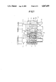
- FIG. 7 is a view similar to FIG. 6 showing the control circuit connector housings and the sensing circuit connector housings completely mated together in latched positions.
- FIG. 8 is a top plan view showing the control circuit connector housings prior to being mated together.
- FIG. 9 is a view similar to FIG. 8 showing the control circuit connector housings partly mated together and one of the sensing circuit connector housing spaced therefrom.
- FIG. 10 is a view similar to FIG. 9 showing that the one sensing circuit connector housing cannot be completely mated with the other sensing circuit connector housing because the control circuit connector housings are not completely mated.
- FIG. 11 is a view similar to FIGS. 9 and 10 showing the control circuit connector housings completely mated so that the sensing circuit connector housings can now be completely mated.
- FIGS. 1 and 2 show the various connector housings that are matable togetherto form an electrical connector to complete electrical sensing and control circuits for use in conjunction with electrical equipment of the type as for example an airbag system of an automobile. It is extremely important that the airbag system is operational, therefore an electrical control circuit is part of the airbag system to control operation thereof while a sensing circuit senses whether the system is in condition for operation and will so indicate if it is not. An important part of the airbag system is the electrical connector that connects the electrical wires of the control and sensing circuits and assures that the connector members are completely mated and securely latched together.
- connector housings Only the connector housings are shown without the inclusion of matable electrical contacts terminated to appropriate electrical wires and securedin position in the connector housings to simplify the description of the invention as these are conventional and need not be shown to understand the present invention; however, the connector housings will be referred toas electrical connectors because that is their intended function.
- Electrical connectors 1 and 2 are part of a support member 3 interconnecting them so that they are parallelly spaced with respect to each other. Electrical connectors 4 and 5 are separate and are electrically matable with electrical connectors 1 and 2, respectively. Electrical connectors 1 and 4 are part of an electrical control circuit while electrical connectors 2 and 5 are part of an electrical sensing circuit. Connectors 1, 2, 4 and 5 include housings 6, 7, 8 and 9, respectively, and these housings and support member 3 are molded from a suitable dielectric material.
- Housing 6 has an exterior projection 10 extending along one side wall, an exterior slot 11 extending along an opposite side wall and a projection 12extending along the bottom wall.
- Housing 8 has interior slots 13 and 15 extending respectively along a side wall and bottom wall and an interior projection 14 extending along an opposite side wall. Projections 10, 12, and slot 11 of housing 6 are matable with slots 13, 15 and projection 14 of housing 8 when connectors 1 and 4 are mated together.
- Housing 7 has an exterior projection 16 and an exterior slot 17 extending along respective sides which respectively mate with interior slot 18 and exterior projection 19 of housing when connectors 2 and 5 are mated together.
- Housings 6, 7, 8 and 9 have contact-receiving passageways 20, 21, 22 and 23, respectively, in which electrical contacts terminated to electrical wires (not shown) are secured preferably by resilient integral housing lances 8a as shown in FIG. 3. Sealing grommets are also secured onto the terminated wires adjacent the contacts for sealing engagement with the passageways.
- Housing 6 also includes an exterior wedge-shaped projection 24 on the upperwall adjacent the front end.
- An exterior projection 25 also extends along the upper wall between projection 24 and the side wall and it includes a latching projection 26 at its front end.
- Housing 8 has an exterior slot 27 in an upper wall which extends between guide opening 35 in a front projection 36 and a surface 27a in alignment with projection 24 on housing 6.
- a sloped surface 28 extends beyond surface 27a in alignment therewith.
- a resilient latch member 29 extends rearwardly from front projection 36 along the upper wall and parallel to slot 27 and is movable relative to the upper wall.
- Cam surface 30 is located on a side surface of latch member 29 in alignment with a guide opening 34 in front projection 36 and in alignment with latching projection 26 of housing 6.
- a latching recess 31 is located in the side oflatch member 29 rearwardly of cam surface 30 and in alignment therewith forlatchably receiving latching projection 26 of housing 6.
- Section 33 at a free end of latch member 29 is for engagement by an operator to operate latch member 29.
- Housing 7 has an exterior wedge-shaped latching projection 37 on an upper surface adjacent a front end.
- Housing 9 has a stiffly-flexible integral latching member provided with a rectangular latching opening 3 and an outwardly-extending section 40 for engagement by an operator to operate latching member 38 about an area 41 at which latching member 38 is pivotally connected to housing 9.
- a hood 9a covers latching member 38 containing opening 9 to protect it and prevent the latching member 38 frombecoming entangled with wires.
- a stiffly-flexible arm 42 extends forwardly from a base member 46 at a bottom of housing 9 between extensions 44 and 45 that extend downwardly from the bottom of housing 9.
- a projection 43 having a tapered front surface and an arcuate rear surface extends downwardly from a front end offlexible arm 42 as best shown in FIGS. 4-6.
- a rectangular opening 47 is located in the upper part of the rear wall of housing 8 to the right of sloped surface 28.
- An L-shaped arm 48 extends downwardly from latch member 29 adjacent its outer end with the free end of arm 48 being disposed within opening 47. Arm 48 limits the horizontal and vertical movement of latch member 29 thereby protecting it from being damaged by excessive horizontal and vertical movement.
- Connectors 1, 2, 4 and 5 operate in accordance with the following description.
- FIG. 5 indicates, when an attempt is made to mate connector 5 with connector 2 to complete the sensing circuit when connector 4 of the control circuit is not mated with connector 1, protrusion 43 on housing 9 engages the front tapered surface of projection 24 on housing 6. As a result, connector 5 cannot be mated with connector 2 which means that thisarrangement performs a check or an indication that connector 4 must first be completely mated with connector 1 before connector 5 can be completely mated with connector 2.
- connector 5 can then be completely mated with connector 2to complete the sensing circuit.
- projection 24 and latching projection 26 of housing 6 pass through respective guide openings 35, 34 of housing 8 and projection 24 moves along slot 27 of housing 8 and engages rear surface 27a thereof while cam surface 30 of latching arm 29 engages latching projection 26 causing latching arm 29 to move inwardly, as shown in FIG. 10, and then tomove outwardly when cam surface 30 moves beyond latching projection 26 whereby latching projection 26 is disposed within latching recess 31, as shown in FIG. 11, when latching arm 29 returns to its normal position thereby latching connectors 1 and 4 in a completely mated position.
- connector 5 can now be mated with connector 2.
- projection 43 of housing 9 moves along sloped surface 28 causing arm 42 tomove upwardly and then projection 43 moves along the top and tapered rear surface of projection 24 on housing 6 and then along recess 27 while the tapered bottom front surface of latching member 38 of housing 9 is moved upwardly as it moves along the tapered front surface of latching projection 37 on housing 7 and then latching member 38 moves down in engagement with housing 7 with latching projection 37 being located withinlatching opening 39 with a front surface of opening 39 in engagement with the rear perpendicular surface of latching projection 37, as shown in FIG.7, thereby latching connectors 2 and 5 together in a completely mated position.
- An audible indication also occurs when connector 5 completely and latchablymates with connector 2 because projection 43 forcefully engages front projection 36, and latching member 38 forcefully engages housing 7 as a result of the elastic forces generated by moving latching member 38 upwardly from its normal position.
- connector 4 If connector 4 is not completely mated with connector 1 because the latching arm 29 of housing 8 is not latched to latching projection 26 of housing 6 by latching projection 26 being positioned within latching recess 31 of latching arm 29 as shown in FIGS. 9 and 10, then connector 5 cannot be mated with connector 2. The reason for this is that latching arm29 has not returned to its normal position thereby positioning surface 32 of latching arm 29 for engagement by extension 44 of housing 9 thereby preventing connector 5 from mating with connector 2. This arrangement performs another check or indication that connectors 1 and 4 are not completely mated.
- connectors 1 and 4 are not completely mated because connector 5 cannot be mated with connector 2, connectors 1 and 4 can then be completely mated by moving them to their completely-mated position or moving connector 5 to its completely-mated position on connector 2 will also move connector 4 to its completely-mated position on connector 1 because extension 44 by engaging surface 32 of latching arm 29 will move connector 4 forwardly causing cam surface 30 of latching arm 29 to move free of latching projection 26 and enable latching arm 29 to move outwardly so that latching projection 26 is received in latching recess 31thereby resulting in connectors 1, 4 and 2, 5 being completely mated and latched together.
- connector 5 After connectors 1, 4 and 2, 5 have been completely mated and latched together, to disconnect them, connector 5 must first be disconnected from connector 2 before connector 4 can be disconnected from connector 1. Thus,this prevents connector 4 from being disconnected from connector 1 unless connector 5 has been disconnected from connector 2.
- latching arm 29 cannot be movedinwardly because extension 44 of housing 9 prevents such movement thereby preventing connector 4 from being disconnected from connector 1 while connector 5 is connected with connector 2.
- One feature of the present invention is that the sensing circuit connectorscannot be connected together unless the control circuit connectors are completely mated together.
- control circuit connectors are partly mated together, the sensing circuit connectors cannot be connected together.
- the partly-mated control circuit connectors can be completely mated together by completely mating the sensing circuit connectors.
- a further feature is that the control circuit connectors cannot be disconnected so long as the sensing circuit connectors are connected together.
- An additional feature is an audible indication of the complete mating of the control circuit connectors and the sensing circuit connectors.
Abstract
Description
Claims (11)
Applications Claiming Priority (2)
| Application Number | Priority Date | Filing Date | Title |
|---|---|---|---|
| JP63084961A JPH0738311B2 (en) | 1988-04-06 | 1988-04-06 | Electrical connector |
| JP63-84961 | 1988-04-06 |
Publications (1)
| Publication Number | Publication Date |
|---|---|
| US4867699A true US4867699A (en) | 1989-09-19 |
Family
ID=13845225
Family Applications (1)
| Application Number | Title | Priority Date | Filing Date |
|---|---|---|---|
| US07/316,737 Expired - Fee Related US4867699A (en) | 1988-04-06 | 1989-02-28 | Connector with checking device |
Country Status (3)
| Country | Link |
|---|---|
| US (1) | US4867699A (en) |
| JP (1) | JPH0738311B2 (en) |
| KR (1) | KR940011574B1 (en) |
Cited By (53)
| Publication number | Priority date | Publication date | Assignee | Title |
|---|---|---|---|---|
| US4979910A (en) * | 1988-09-20 | 1990-12-25 | Labinal S.A. | Electrical connector housing assembly |
| US5017147A (en) * | 1989-05-15 | 1991-05-21 | Yazaki Corporation | Connectors with cover providing connection sequence control |
| EP0477855A2 (en) * | 1990-09-27 | 1992-04-01 | Hosiden Corporation | Plug and socket |
| FR2669471A1 (en) * | 1990-11-16 | 1992-05-22 | Ecia Equip Composants Ind Auto | PERFECT ELECTRICAL CONNECTOR WITH DETROMPER AND ITS APPLICATION IN PARTICULAR TO ELECTRIC MOTORS. |
| US5151048A (en) * | 1990-07-27 | 1992-09-29 | Hirose Electric Co., Ltd. | Failsafe electrical connector |
| US5163848A (en) * | 1990-09-27 | 1992-11-17 | Yazaki Corporation | Incomplete fitting prevention connector |
| US5226834A (en) * | 1990-10-12 | 1993-07-13 | Yazaki Corporation | Incomplete fitting prevention connector |
| US5338219A (en) * | 1992-07-23 | 1994-08-16 | Molex Incorporated | Electric connector |
| US5342215A (en) * | 1993-06-21 | 1994-08-30 | Molex Incorporated | Releasable latching system for electrical connectors |
| US5378168A (en) * | 1992-10-06 | 1995-01-03 | Sumitomo Wiring Systems | Connector |
| US5403199A (en) * | 1993-10-21 | 1995-04-04 | Electrical Mechanical Products Inc. | Low insertion force high current terminal |
| US5429525A (en) * | 1993-07-19 | 1995-07-04 | Mccoy; Phillip A. | Connector assembly |
| US5435742A (en) * | 1994-02-14 | 1995-07-25 | Molex Incorporated | Electrical connector position assurance system |
| US5462450A (en) * | 1992-09-07 | 1995-10-31 | Yazaki Corporation | Connector disconnection sensing mechanism |
| US5572395A (en) * | 1993-12-21 | 1996-11-05 | International Business Machines Corporation | Circuit for controlling current in an adapter card |
| US5609500A (en) * | 1996-01-02 | 1997-03-11 | Motorola, Inc. | Accessory connector alignment and support plate |
| US5628649A (en) * | 1994-06-03 | 1997-05-13 | Yazaki Corporation | Lock detecting structure of connector |
| US5746618A (en) * | 1995-07-14 | 1998-05-05 | Augat Inc. | Squib connector for automotive air bag assembly |
| US5882224A (en) * | 1996-08-28 | 1999-03-16 | Thomas & Betts International, Inc. | Squib connector socker assembly having shorting clip for automotive air bags |
| US6086403A (en) * | 1996-12-09 | 2000-07-11 | Hon Hai Precision Ind. Co., Ltd. | Electrical connector |
| US6165024A (en) * | 1998-09-11 | 2000-12-26 | Hon Hai Precision Ind. Co, Ltd. | Arrangement for preventing mismatching of connector assembly |
| US6394855B1 (en) * | 2000-10-06 | 2002-05-28 | Raytheon Company | In-line multi-plug self-aligning connector |
| US6447346B2 (en) * | 2000-03-02 | 2002-09-10 | Kabushiki Kaisha Tokai Rika Denki Seisakusho | Multipolar connector apparatus with force transmitting member |
| GB2381392A (en) * | 2001-10-29 | 2003-04-30 | Delphi Tech Inc | Two part electrical connector having GO-NOGO feature |
| US20030093163A1 (en) * | 2001-11-09 | 2003-05-15 | Xerox Corporation | Multi-device inter-connection securing apparatus |
| US20050106940A1 (en) * | 2003-10-31 | 2005-05-19 | Medtronic, Inc | Assembly and method for connecting electrical medical components |
| US20050184264A1 (en) * | 2004-02-23 | 2005-08-25 | Christopher Tesluk | Fluid conduit connector apparatus |
| US20050250350A1 (en) * | 2000-06-08 | 2005-11-10 | Yoshihiro Nakashima | Gas generator for air bag and air bag apparatus |
| FR2886065A1 (en) * | 2005-05-23 | 2006-11-24 | Renault Sas | Electric connection arrangement for motor vehicle, has locking units conformed such that signal connector is only locked in connected position after locking of power connector in mounted position |
| US20080035276A1 (en) * | 2004-08-24 | 2008-02-14 | Paul Voss Gmbh & Co. Kg | Articulated Arm For An Awning And Method For The Production Thereof |
| DE102006044655B3 (en) * | 2006-09-21 | 2008-02-21 | Tyco Electronics Amp Gmbh | Electrical plug connector arrangement for air bag system or high voltage system, has locking device formed as slider and mounted at housing in movable manner, where locking device is located between plugs at housing |
| US20080070441A1 (en) * | 2004-09-29 | 2008-03-20 | Frederic Chazottes | Locking Device for Connector Elements and a Connector Provided with Said Device |
| US20080077063A1 (en) * | 2006-09-21 | 2008-03-27 | Tyco Healthcare Group Lp | Safety Connector Apparatus |
| DE102007003375A1 (en) | 2007-01-23 | 2008-07-31 | Tyco Electronics Amp Gmbh | Electrical connectors for hybrid or fuel cell vehicles, has two catch devices, which are arranged on individual electrical connector |
| US20080182447A1 (en) * | 2007-01-29 | 2008-07-31 | Yazaki Europe Ltd. | Connector assembly with a slider |
| US20090035981A1 (en) * | 2007-07-31 | 2009-02-05 | Mea Technologies Pte. Ltd. | Electric connector |
| US20090240178A1 (en) * | 2008-03-20 | 2009-09-24 | Tyco Healthcare Group Lp | Safety connector assembly |
| WO2010003507A1 (en) * | 2008-06-17 | 2010-01-14 | Leoni Bordnetz-Systeme Gmbh | High-voltage plug connection for motor vehicles |
| EP2159888A2 (en) * | 2008-08-28 | 2010-03-03 | Delphi Technologies, Inc. | High Voltage Connector and Interlocking Loop Connector Assembly |
| US20100130039A1 (en) * | 2008-11-26 | 2010-05-27 | Yazaki Corporation | Complex connector |
| US20100317214A1 (en) * | 2008-02-22 | 2010-12-16 | Mulot Gerard | Electrical connector system with power and command connectors |
| WO2011003950A1 (en) * | 2009-07-09 | 2011-01-13 | Kostal Kontakt Systeme Gmbh | Electric plug connector |
| US7871387B2 (en) | 2004-02-23 | 2011-01-18 | Tyco Healthcare Group Lp | Compression sleeve convertible in length |
| EP2274801A1 (en) * | 2008-05-08 | 2011-01-19 | Johnson Controls Hybrid and Recycling GmbH | Battery for hybrid vehicles with a safety device for interrupting a high-voltage circuit |
| US8398415B1 (en) * | 2011-11-18 | 2013-03-19 | Yazaki North America, Inc. | Connector assembly for assembling/disassembling four connectors using a staged-release member |
| US20130079754A1 (en) * | 2011-09-26 | 2013-03-28 | General Electric Company | Connection system |
| US9935389B1 (en) * | 2017-02-23 | 2018-04-03 | Sumitomo Wiring Systems, Ltd. | Inline connector housing assemblies with removable TPA |
| US20190312394A1 (en) * | 2018-04-04 | 2019-10-10 | Commscope Technologies Llc | Ganged coaxial connector assembly |
| US20190363481A1 (en) * | 2018-04-04 | 2019-11-28 | Commscope Technologies Llc | Ganged coaxial connector assembly |
| US20200044388A1 (en) * | 2018-08-01 | 2020-02-06 | Yazaki Corporation | Connector |
| US10847932B2 (en) * | 2019-02-01 | 2020-11-24 | Sumitomo Wiring Systems, Ltd. | Lever-type connector |
| USD920925S1 (en) * | 2017-12-26 | 2021-06-01 | Omron Corporation | Push switch |
| US11527846B2 (en) | 2016-02-12 | 2022-12-13 | Commscope Technologies Llc | Ganged coaxial connector assembly |
Families Citing this family (3)
| Publication number | Priority date | Publication date | Assignee | Title |
|---|---|---|---|---|
| JPH0240876A (en) * | 1988-07-29 | 1990-02-09 | Mazda Motor Corp | Feeding circuit of electrical equipment |
| JP2729561B2 (en) * | 1993-04-16 | 1998-03-18 | 矢崎総業株式会社 | connector |
| JP3170178B2 (en) * | 1995-06-12 | 2001-05-28 | 矢崎総業株式会社 | Connector misconnection prevention device |
Citations (4)
| Publication number | Priority date | Publication date | Assignee | Title |
|---|---|---|---|---|
| US3970354A (en) * | 1974-11-04 | 1976-07-20 | Amp Incorporated | Intrinsic certification assembly technique for wiring components into an electrical apparatus |
| US4006959A (en) * | 1974-11-04 | 1977-02-08 | Amp Incorporated | Intrinsic certification assembly technique for wiring components into an electrical apparatus |
| US4010996A (en) * | 1976-01-14 | 1977-03-08 | Amp Incorporated | Intrinsic certification assembly technique for wiring components into an electrical apparatus |
| US4050764A (en) * | 1976-01-14 | 1977-09-27 | Amp Incorporated | Intrinsic certification assembly technique for wiring components into an electrical apparatus |
Family Cites Families (1)
| Publication number | Priority date | Publication date | Assignee | Title |
|---|---|---|---|---|
| JPH077682B2 (en) * | 1988-01-28 | 1995-01-30 | マツダ株式会社 | Electrical connection device |
-
1988
- 1988-04-06 JP JP63084961A patent/JPH0738311B2/en not_active Expired - Lifetime
-
1989
- 1989-02-28 US US07/316,737 patent/US4867699A/en not_active Expired - Fee Related
- 1989-04-06 KR KR1019890004504A patent/KR940011574B1/en not_active IP Right Cessation
Patent Citations (4)
| Publication number | Priority date | Publication date | Assignee | Title |
|---|---|---|---|---|
| US3970354A (en) * | 1974-11-04 | 1976-07-20 | Amp Incorporated | Intrinsic certification assembly technique for wiring components into an electrical apparatus |
| US4006959A (en) * | 1974-11-04 | 1977-02-08 | Amp Incorporated | Intrinsic certification assembly technique for wiring components into an electrical apparatus |
| US4010996A (en) * | 1976-01-14 | 1977-03-08 | Amp Incorporated | Intrinsic certification assembly technique for wiring components into an electrical apparatus |
| US4050764A (en) * | 1976-01-14 | 1977-09-27 | Amp Incorporated | Intrinsic certification assembly technique for wiring components into an electrical apparatus |
Non-Patent Citations (2)
| Title |
|---|
| Spec. & Dwgs. from Japanese Appln. No. 62/307332, Filed on 12 4 87. * |
| Spec. & Dwgs. from Japanese Appln. No. 62/307332, Filed on 12-4-87. |
Cited By (87)
| Publication number | Priority date | Publication date | Assignee | Title |
|---|---|---|---|---|
| US4979910A (en) * | 1988-09-20 | 1990-12-25 | Labinal S.A. | Electrical connector housing assembly |
| US5017147A (en) * | 1989-05-15 | 1991-05-21 | Yazaki Corporation | Connectors with cover providing connection sequence control |
| US5151048A (en) * | 1990-07-27 | 1992-09-29 | Hirose Electric Co., Ltd. | Failsafe electrical connector |
| US5163848A (en) * | 1990-09-27 | 1992-11-17 | Yazaki Corporation | Incomplete fitting prevention connector |
| EP0477855A2 (en) * | 1990-09-27 | 1992-04-01 | Hosiden Corporation | Plug and socket |
| EP0477855A3 (en) * | 1990-09-27 | 1992-09-23 | Hosiden Corporation | Plug and socket |
| US5226834A (en) * | 1990-10-12 | 1993-07-13 | Yazaki Corporation | Incomplete fitting prevention connector |
| EP0487360A1 (en) * | 1990-11-16 | 1992-05-27 | Ecia - Equipements Et Composants Pour L'industrie Automobile | Electrical connector with means for preventing incorrect coupling and its application especially to electric motors |
| FR2669471A1 (en) * | 1990-11-16 | 1992-05-22 | Ecia Equip Composants Ind Auto | PERFECT ELECTRICAL CONNECTOR WITH DETROMPER AND ITS APPLICATION IN PARTICULAR TO ELECTRIC MOTORS. |
| US5338219A (en) * | 1992-07-23 | 1994-08-16 | Molex Incorporated | Electric connector |
| US5462450A (en) * | 1992-09-07 | 1995-10-31 | Yazaki Corporation | Connector disconnection sensing mechanism |
| US5378168A (en) * | 1992-10-06 | 1995-01-03 | Sumitomo Wiring Systems | Connector |
| US5342215A (en) * | 1993-06-21 | 1994-08-30 | Molex Incorporated | Releasable latching system for electrical connectors |
| US5429525A (en) * | 1993-07-19 | 1995-07-04 | Mccoy; Phillip A. | Connector assembly |
| US5403199A (en) * | 1993-10-21 | 1995-04-04 | Electrical Mechanical Products Inc. | Low insertion force high current terminal |
| US5572395A (en) * | 1993-12-21 | 1996-11-05 | International Business Machines Corporation | Circuit for controlling current in an adapter card |
| US5435742A (en) * | 1994-02-14 | 1995-07-25 | Molex Incorporated | Electrical connector position assurance system |
| US5628649A (en) * | 1994-06-03 | 1997-05-13 | Yazaki Corporation | Lock detecting structure of connector |
| US5746618A (en) * | 1995-07-14 | 1998-05-05 | Augat Inc. | Squib connector for automotive air bag assembly |
| US5609500A (en) * | 1996-01-02 | 1997-03-11 | Motorola, Inc. | Accessory connector alignment and support plate |
| US5882224A (en) * | 1996-08-28 | 1999-03-16 | Thomas & Betts International, Inc. | Squib connector socker assembly having shorting clip for automotive air bags |
| US6145193A (en) * | 1996-08-28 | 2000-11-14 | Thomas & Betts International, Inc. | Method of forming a squib connector socket assembly having shorting clip for automotive air bags |
| US6086403A (en) * | 1996-12-09 | 2000-07-11 | Hon Hai Precision Ind. Co., Ltd. | Electrical connector |
| US6165024A (en) * | 1998-09-11 | 2000-12-26 | Hon Hai Precision Ind. Co, Ltd. | Arrangement for preventing mismatching of connector assembly |
| AU769906B2 (en) * | 2000-03-02 | 2004-02-12 | Kabushiki Kaisha Tokai-Rika-Denki-Seisakusho | Connector apparatus |
| US6447346B2 (en) * | 2000-03-02 | 2002-09-10 | Kabushiki Kaisha Tokai Rika Denki Seisakusho | Multipolar connector apparatus with force transmitting member |
| US7152874B2 (en) * | 2000-06-08 | 2006-12-26 | Daicel Chemical Industries, Ltd. | Gas generator for air bag and air bag apparatus |
| US20050250350A1 (en) * | 2000-06-08 | 2005-11-10 | Yoshihiro Nakashima | Gas generator for air bag and air bag apparatus |
| US6394855B1 (en) * | 2000-10-06 | 2002-05-28 | Raytheon Company | In-line multi-plug self-aligning connector |
| GB2381392A (en) * | 2001-10-29 | 2003-04-30 | Delphi Tech Inc | Two part electrical connector having GO-NOGO feature |
| GB2381392B (en) * | 2001-10-29 | 2003-12-03 | Delphi Tech Inc | Two-part electrical connector |
| US6676439B2 (en) * | 2001-11-09 | 2004-01-13 | Xerox Corporation | Multi-device inter-connection securing apparatus |
| US20030093163A1 (en) * | 2001-11-09 | 2003-05-15 | Xerox Corporation | Multi-device inter-connection securing apparatus |
| US20050106940A1 (en) * | 2003-10-31 | 2005-05-19 | Medtronic, Inc | Assembly and method for connecting electrical medical components |
| US7810519B2 (en) | 2004-02-23 | 2010-10-12 | Tyco Healthcare Group Lp | Fluid conduit connector apparatus |
| US20050184264A1 (en) * | 2004-02-23 | 2005-08-25 | Christopher Tesluk | Fluid conduit connector apparatus |
| US7490620B2 (en) | 2004-02-23 | 2009-02-17 | Tyco Healthcare Group Lp | Fluid conduit connector apparatus |
| US20100276619A1 (en) * | 2004-02-23 | 2010-11-04 | Tyco Healthcare Group Lp | Fluid conduit connector apparatus |
| US20090146092A1 (en) * | 2004-02-23 | 2009-06-11 | Tyco Healthcare Group Lp | Fluid conduit connector apparatus |
| US8256459B2 (en) | 2004-02-23 | 2012-09-04 | Tyco Healthcare Group Lp | Fluid conduit connector apparatus |
| US7871387B2 (en) | 2004-02-23 | 2011-01-18 | Tyco Healthcare Group Lp | Compression sleeve convertible in length |
| US20080035276A1 (en) * | 2004-08-24 | 2008-02-14 | Paul Voss Gmbh & Co. Kg | Articulated Arm For An Awning And Method For The Production Thereof |
| US7645088B2 (en) * | 2004-08-24 | 2010-01-12 | Paul Voss Gmbh & Co. Kg | Articulated arm for an awning and method for the production thereof |
| US20080070441A1 (en) * | 2004-09-29 | 2008-03-20 | Frederic Chazottes | Locking Device for Connector Elements and a Connector Provided with Said Device |
| US7785146B2 (en) | 2004-09-29 | 2010-08-31 | Fci | Locking device for connector elements and a connector provided with said device |
| WO2007003803A3 (en) * | 2005-05-23 | 2007-02-22 | Renault Sa | Arrangement for securely connecting an electronic device to at least two other electronic devices |
| FR2886065A1 (en) * | 2005-05-23 | 2006-11-24 | Renault Sas | Electric connection arrangement for motor vehicle, has locking units conformed such that signal connector is only locked in connected position after locking of power connector in mounted position |
| US20080274628A1 (en) * | 2005-05-23 | 2008-11-06 | Renault S.A.S. | Arrangement for Securely Connecting an Electronic Device to at Least Two Other Electronic Devices |
| WO2007003803A2 (en) * | 2005-05-23 | 2007-01-11 | Renault S.A.S. | Arrangement for securely connecting an electronic device to at least two other electronic devices |
| US20080077063A1 (en) * | 2006-09-21 | 2008-03-27 | Tyco Healthcare Group Lp | Safety Connector Apparatus |
| US20080076290A1 (en) * | 2006-09-21 | 2008-03-27 | Carsten Buck | Electrical Plug Connector Assembly Having A Defined Plug-In Sequence |
| US9687249B2 (en) | 2006-09-21 | 2017-06-27 | Covidien Lp | Safety connector assembly |
| US7544074B2 (en) | 2006-09-21 | 2009-06-09 | Tyco Electroncis Amp Gmbh | Electrical plug connector assembly having a defined plug-in sequence |
| US8287517B2 (en) | 2006-09-21 | 2012-10-16 | Tyco Healtcare Group Lp | Safety connector assembly |
| US8257286B2 (en) | 2006-09-21 | 2012-09-04 | Tyco Healthcare Group Lp | Safety connector apparatus |
| DE102006044655B3 (en) * | 2006-09-21 | 2008-02-21 | Tyco Electronics Amp Gmbh | Electrical plug connector arrangement for air bag system or high voltage system, has locking device formed as slider and mounted at housing in movable manner, where locking device is located between plugs at housing |
| DE102007003375B4 (en) * | 2007-01-23 | 2014-09-18 | Tyco Electronics Amp Gmbh | Electrical plug connection |
| DE102007003375A1 (en) | 2007-01-23 | 2008-07-31 | Tyco Electronics Amp Gmbh | Electrical connectors for hybrid or fuel cell vehicles, has two catch devices, which are arranged on individual electrical connector |
| US20080182447A1 (en) * | 2007-01-29 | 2008-07-31 | Yazaki Europe Ltd. | Connector assembly with a slider |
| US20090035981A1 (en) * | 2007-07-31 | 2009-02-05 | Mea Technologies Pte. Ltd. | Electric connector |
| US7544081B2 (en) * | 2007-07-31 | 2009-06-09 | Mea Technologies Pte. Ltd. | Electric connector |
| US20100317214A1 (en) * | 2008-02-22 | 2010-12-16 | Mulot Gerard | Electrical connector system with power and command connectors |
| US8241052B2 (en) * | 2008-02-22 | 2012-08-14 | Fci Automotive Holding | Electrical connector system with power and command connectors |
| US8257287B2 (en) | 2008-03-20 | 2012-09-04 | Tyco Healthcare Group Lp | Safety connector assembly |
| US20090240178A1 (en) * | 2008-03-20 | 2009-09-24 | Tyco Healthcare Group Lp | Safety connector assembly |
| US20110079494A1 (en) * | 2008-05-08 | 2011-04-07 | Johnson Controls Hybrid And Recycling Gmbh | Battery for hybrid vehicles with a safety device for interrupting a high-voltage circuit |
| EP2274801A1 (en) * | 2008-05-08 | 2011-01-19 | Johnson Controls Hybrid and Recycling GmbH | Battery for hybrid vehicles with a safety device for interrupting a high-voltage circuit |
| DE102008028785B4 (en) * | 2008-06-17 | 2012-02-16 | Continental Automotive Gmbh | High-voltage connector for motor vehicles |
| WO2010003507A1 (en) * | 2008-06-17 | 2010-01-14 | Leoni Bordnetz-Systeme Gmbh | High-voltage plug connection for motor vehicles |
| EP2159888A3 (en) * | 2008-08-28 | 2013-12-04 | Delphi Technologies, Inc. | High Voltage Connector and Interlocking Loop Connector Assembly |
| EP2159888A2 (en) * | 2008-08-28 | 2010-03-03 | Delphi Technologies, Inc. | High Voltage Connector and Interlocking Loop Connector Assembly |
| US7934939B2 (en) * | 2008-11-26 | 2011-05-03 | Yazaki Corporation | Complex connector |
| US20100130039A1 (en) * | 2008-11-26 | 2010-05-27 | Yazaki Corporation | Complex connector |
| WO2011003950A1 (en) * | 2009-07-09 | 2011-01-13 | Kostal Kontakt Systeme Gmbh | Electric plug connector |
| US20130079754A1 (en) * | 2011-09-26 | 2013-03-28 | General Electric Company | Connection system |
| US8398415B1 (en) * | 2011-11-18 | 2013-03-19 | Yazaki North America, Inc. | Connector assembly for assembling/disassembling four connectors using a staged-release member |
| US11527846B2 (en) | 2016-02-12 | 2022-12-13 | Commscope Technologies Llc | Ganged coaxial connector assembly |
| US9935389B1 (en) * | 2017-02-23 | 2018-04-03 | Sumitomo Wiring Systems, Ltd. | Inline connector housing assemblies with removable TPA |
| USD920925S1 (en) * | 2017-12-26 | 2021-06-01 | Omron Corporation | Push switch |
| US10978840B2 (en) * | 2018-04-04 | 2021-04-13 | Commscope Technologies Llc | Ganged coaxial connector assembly |
| US10950970B2 (en) * | 2018-04-04 | 2021-03-16 | Commscope Technologies Llc | Ganged coaxial connector assembly |
| US20190363481A1 (en) * | 2018-04-04 | 2019-11-28 | Commscope Technologies Llc | Ganged coaxial connector assembly |
| US20190312394A1 (en) * | 2018-04-04 | 2019-10-10 | Commscope Technologies Llc | Ganged coaxial connector assembly |
| US11824316B2 (en) | 2018-04-04 | 2023-11-21 | Commscope Technologies Llc | Ganged coaxial connector assembly |
| US10819067B2 (en) * | 2018-08-01 | 2020-10-27 | Yazaki Corporation | Connector having an engaged part contacting an engagement projection after a tip end projection of the engaged part faces the engagement projection |
| US20200044388A1 (en) * | 2018-08-01 | 2020-02-06 | Yazaki Corporation | Connector |
| US10847932B2 (en) * | 2019-02-01 | 2020-11-24 | Sumitomo Wiring Systems, Ltd. | Lever-type connector |
Also Published As
| Publication number | Publication date |
|---|---|
| KR940011574B1 (en) | 1994-12-21 |
| JPH01274368A (en) | 1989-11-02 |
| KR890016711A (en) | 1989-11-29 |
| JPH0738311B2 (en) | 1995-04-26 |
Similar Documents
| Publication | Publication Date | Title |
|---|---|---|
| US4867699A (en) | Connector with checking device | |
| US5435742A (en) | Electrical connector position assurance system | |
| US5863216A (en) | Short-circuiting terminal fitting and connector therefor | |
| US6135802A (en) | Cover-equipped connector | |
| US5749747A (en) | Partial-fitting prevention connector | |
| US5827086A (en) | Half-fitting prevention connector | |
| US5647757A (en) | Electrical connector with terminal position assurance | |
| US6019629A (en) | Connector | |
| EP0449239B1 (en) | A connector engagement detecting apparatus | |
| US5273456A (en) | Mate sensing connector system | |
| US5562486A (en) | Lock detection connector | |
| EP0448084A1 (en) | A connector engagement detecting apparatus | |
| US5015199A (en) | Electric connector | |
| US4988307A (en) | Circuit shorting connector | |
| KR0159508B1 (en) | Shunted connector assembly and interdigitated shunt assembly | |
| EP0836251B1 (en) | Electrical connector with shunt | |
| EP0657968B1 (en) | Lock detection connector | |
| US6361334B1 (en) | Cover-provided connector | |
| US6948953B2 (en) | Connector connecting construction and a connector connecting method | |
| JP3457172B2 (en) | Connector mating structure | |
| US6247957B1 (en) | Connector with detection member | |
| JP3189202B2 (en) | Connector connection detection device | |
| US5551887A (en) | Connector | |
| EP0666619B1 (en) | Electrical connector | |
| JP3619300B2 (en) | Connector coupling detection device |
Legal Events
| Date | Code | Title | Description |
|---|---|---|---|
| AS | Assignment |
Owner name: AMP INCORPORATED, A CORP. OF NJ, PENNSYLVANIA Free format text: ASSIGNMENT OF ASSIGNORS INTEREST.;ASSIGNOR:AMP (JAPAN) LTD.;REEL/FRAME:005172/0855 Effective date: 19890228 Owner name: AMP (JAPAN) LIMITED, JAPAN Free format text: ASSIGNMENT OF ASSIGNORS INTEREST.;ASSIGNORS:ODA, KENZO;BETSUI, KAZUHISA;REEL/FRAME:005172/0853 Effective date: 19890210 |
|
| FEPP | Fee payment procedure |
Free format text: PAYOR NUMBER ASSIGNED (ORIGINAL EVENT CODE: ASPN); ENTITY STATUS OF PATENT OWNER: LARGE ENTITY |
|
| FPAY | Fee payment |
Year of fee payment: 4 |
|
| FPAY | Fee payment |
Year of fee payment: 8 |
|
| REMI | Maintenance fee reminder mailed | ||
| LAPS | Lapse for failure to pay maintenance fees | ||
| FP | Lapsed due to failure to pay maintenance fee |
Effective date: 20010919 |
|
| STCH | Information on status: patent discontinuation |
Free format text: PATENT EXPIRED DUE TO NONPAYMENT OF MAINTENANCE FEES UNDER 37 CFR 1.362 |