US4863271A - Optical combiner for a ring laser gyro - Google Patents
Optical combiner for a ring laser gyro Download PDFInfo
- Publication number
- US4863271A US4863271A US07/151,617 US15161788A US4863271A US 4863271 A US4863271 A US 4863271A US 15161788 A US15161788 A US 15161788A US 4863271 A US4863271 A US 4863271A
- Authority
- US
- United States
- Prior art keywords
- beams
- prisms
- sub
- laser
- prism
- Prior art date
- Legal status (The legal status is an assumption and is not a legal conclusion. Google has not performed a legal analysis and makes no representation as to the accuracy of the status listed.)
- Expired - Fee Related
Links
Images


Classifications
-
- G—PHYSICS
- G01—MEASURING; TESTING
- G01C—MEASURING DISTANCES, LEVELS OR BEARINGS; SURVEYING; NAVIGATION; GYROSCOPIC INSTRUMENTS; PHOTOGRAMMETRY OR VIDEOGRAMMETRY
- G01C19/00—Gyroscopes; Turn-sensitive devices using vibrating masses; Turn-sensitive devices without moving masses; Measuring angular rate using gyroscopic effects
- G01C19/58—Turn-sensitive devices without moving masses
- G01C19/64—Gyrometers using the Sagnac effect, i.e. rotation-induced shifts between counter-rotating electromagnetic beams
- G01C19/66—Ring laser gyrometers
- G01C19/661—Ring laser gyrometers details
- G01C19/662—Ring laser gyrometers details signal readout; dither compensators
Definitions
- Ring laser gyros use ring lasers whose laser path is usually imbedded in a dimensionally stable block of glass-ceramic material.
- a closed gas-filled bore is fabricated with three or more, typically four, corner mirrors to circulate counterpropagating laser beams around a closed path.
- Means are provided to deliver energy to the laser.
- the Sagnac effect causes the two counterpropagating laser beams to vary in frequency. The difference in frequency between the beams is a measure of the angular velocity of the turning about that axis.
- one of the corner mirrors transmits a part of both beams through its transparent substrate.
- the amount of transmitted beam is on the order to 0.01% of the beam's energy.
- An optical combining system is used to combine the two beams to obtain moving interference fringes that may be counted.
- the rate of the counter is then a measure of the angular velocity of the ring laser about its sensing axis, while the direction of fringe motion indicates the sense of rotation.
- parts of the two counterpropagating beams are also extracted at a second corner mirror, and the intensities of the extracted laser beams are monitored and used to servo the inward and outward motion of one or more of the other corner mirrors to tune the laser cavity.
- the finesse of the ring laser cavity is reduced. Reduction of the finesse of the ring laser reduces its accuracy as a measuring instrument.
- the claimed apparatus herein has a beam-splitting mirror and a glue line of finite but very small thickness. That the path lengths thus are slightly different for the two beams, and that difference is temperature sensitive, but very small.
- only one partly transmitting corner mirror is used in the laser cavity, and the finesse of the ring laser is thereby improved.
- the apparatus of this invention on a single corner mirror of a ring laser gyro uses a composite prism whose trunk is fabricated of two substantially identical juxtaposed sub-prisms having beam splitters in the region where laser beams cross their common boundary.
- the beam splitter regions are very thin dielectric films, typically no thicker than a fraction of a wavelength of the laser light. Dielectric films, such as titanium dioxide, are used for the splitters so that the geometrical path lengths of interfering beams are almost exactly the same.
- the two sub-prisms preferably have the same index of refraction, and, in all embodiments, the output mirror should be essentially a plane parallel.
- a plano substrate with a thirty arc second or more wedge is all but intolerable since it produces fringes which are out of the range of the combining optics unless the wedge angle is properly oriented with respect to the lasing plane. It would appear that the above statement excludes curved mirrors as output mirrors, but in practical cases this is not so. For example, for mirrors whose radius of curvature is in the one to ten M range, the height of the chord is approximately ten Angstroms. In the worst case for a mirror 0.8 inch or about two centimeter in diameter, the maximum usable wedge is about 10 -4 arcseconds which is negligible.
- the glue line is the only assymetric part of this prism and is of the order of 100 wavelengths thick. This represents a significant reduction in the centimeter type difference in previous designs. Furthermore the difference in pathlength may be removed by taking the differential output of two heterodyne sensors.
- the optical combiner is fabricated in four parts, and it is important that all parts are of substantially the same material as the mirror substrate: frequently a dimensionally stable material such as that known by the trade mark Zerodur.
- the outwardly-extending trunk of the assembled composite prism is substantially rectangular in cross-section. It is split into two identical sub-prisms with negligible-thickness beam splitters and glue line at the common interface of the sub-prisms. It has a slanted outward end carrying two light combining Meterodyne sensors.
- the two laser beams entering the mirror are refracted and diverge continuing, in the sub-prisms of the trunk, toward two opposite side faces of the composite prism.
- the opposite side faces form beam splitters which reflect the received beams while also transmitting them.
- the reflected laser beams converge in regions of the common boundary between the two touching sub-prisms, and substantially-no-thickness beam splitters are positioned in the reflected beams at those regions.
- the beam splitters at the boundary both reflect and transmit their intercepted laser beams.
- the reflected and transmitted beams interact or heterodyne to form light fringes, and light heterodyne sensors are placed on the ends of the sub-prisms to intercept the fringes.
- the composite prism is turned slightly, on the order of one minute of arc, about an axis that is parallel to the plane of the ring laser path and the common plane between the two sub-prisms.
- the turning of the composite prism causes one or the other of the double light heterodyne sensors to sense the motion of the fringes before the other one of the double light heterodyne sensors senses it, and the direction of rotation of the ring laser is determined by which heterodyne sensor first detects a particular fringe.
- the count rate of the fringes is a measure of the angular velocity of the ring laser.
- the laser light travels outward fromthe partly transmitting ring laser corner mirror substrate, to reduce the outward extension of the prism from the ring laser gyro
- a second embodiment has the composite prism lying flat on the substrate of the partly transmitting corner mirror.
- the second embodiment uses a forty five degree prism surface to turn the laser light through a right angle to deliver the outwardly directed laser beams into a direction parallel to the surface of the mirror substrate.
- the first two embodiments also have auxiliary prisms appended to the sub-prisms, supporting auxiliary light amplitude sensors used for controlling the path length of the ring laser.
- the latter amplitude sensors produce electrical signals, that are measures of the intensity of their intercepted beams, for tune the cavity.
- the sub-prisms are right triangular prisms, and the composite prism is triangular. It has no auxiliary prisms and only the light combining light heterodyne sensors. As in the prior art, path length is controlled from a second corner mirror. Alternately, this may have a forty five degree reflecting face as in the second embodiment.
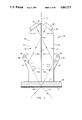
- FIG. 1 is a profile view of a typical four-corner-mirror ring laser, showing three embodiments of the combining prism of the invention.
- FIG. 2 is an enlarged profile view of a first embodiment of the invention, at 2--2 in FIG. 1, showing the direction of beam propagation within the prism.
- FIG. 3 is a view taken from the right in FIG. 2, showing beam directions.
- FIG. 4 is a view taken from the top in FIG. 2, showing the beam directions.
- FIG. 5 is a view of the prism used in the second embodiment, at 5--5 in FIG. 1, of this invention, showing the direction of the laser beams through the prism.
- FIG. 6 is a view taken from the top in FIG. 5, showing beam directions.
- FIG. 7 is a view taken from the side in FIG. 6, showing beam directions.
- FIG. 8 is a view of the prism used in the third embodiment, at 8--8 in FIG. 1, of this invention, showing the direction of the laser beams through the prism.
- FIG. 9 is a view taken from the right in FIG. 8, showing beam directions.
- FIG. 10 is a view taken from the top in FIG. 8, showing beam directions.
- a typical four-corner-mirror ring laser block 10 is shown in FIG. 1.
- the bores 12A, B, C, D intersect at the corner mirrors 14, 16, 18, 20.
- a ring laser would have only one of prisms 22, 23, 24, but they are all shown, for convenience and comparison, on the same Figure.
- the description of structure 22 may be understood from FIGS. 2, 3 and 4.
- the mirror 14 has a substrate 26. Upstanding on the substrate 26 is the composite rectangularly shaped column prism 22. All of the faces of the composite prism 22 are planar.
- the base 27 of the composite prism 22 is mounted upon the substrate 26, and it typically is glued to the substrate.
- the composite prism 22 is formed of a rectangular-cross-section shaped column whose faces 30, and 34 are shown upright, perpendicular to the base 27, and parallel to each other.
- the other side surfaces 28 and 32 are not critical because the laser beams do not cross those surfaces.
- the top of the composite column prism 22 is formed of two intersecting planar surfaces 36 and 38 inclined at such an angle that the incident beams are about ten degrees from the normal.
- the composite prism 22 is fabricated of two pieces or sub-prisms 40 and 42, fastened together at the interface surface 44.
- the surface 44 at the common boundary between the pieces 40 and 42 is preferably an absorbtion layer except that a beam splitter mirror 46 is positioned where that boundary is penetrated by the incoming laser beams.
- the beam splitter 46 is shown with a substantial thickness, in practice it is a thin film that is tuned to the laser frequency and has a thickness that is only approximately a wavelength of the laser beam.
- the glue line is the only assymetric part of this prism and is of the order of 100 wavelengths thick. This is a significant reduction in the centimeter type difference in pathlength of previous designs. Furthermore the temperature sensitive error caused by the difference in pathlength may be removed by taking the differential output of two heterodyne sensors 64 and 66 which are positioned symmetrically.
- At least the regions 50 and 52 of the faces 34 and 30 of the members 40 and 42 must be both light-reflecting and light-transmitting.
- the regions 50, 52 are shown with a thickness, but that is only to designate the region. They may in fact be very thin films similar to the beam splitter 46.
- Two auxiliary prisms 54 and 56 extend outward from and are attached to the surfaces 34 and 30, respectively, to receive light through the regions 50 and 52.
- the light heterodyne sensors 64 and 66 are dual to sense fringes generated by the beat frequency between the two counterpropagating laser beams. The fringes travel over the faces of the dual heterodyne light sensors, and the phase difference between the lights from the two heterodyne sensors of each dual heterodyne light sensor package is used to determine the direction of rotation of the ring laser gyro.
- the mirror substrate 26, the prism parts 40, 42, and the auxiliary prisms 54, 56 are preferably fabricated of a dimensionally stable glass-ceramic material such as that material known by the trademark "Zerodur".
- the incoming laser beams transit through the surface of the counter-propagating laser beams 12B, 12A enter the mirror surface 14, and, as shown at 70A, 72A, they are refracted in the substrate 26 and the sub-prisms 40, 42. They are, as shown at 70C, 72C, reflected at 50, 52 into the region 46 of the common boundary 44 between the prisms 40, 42. At the region 46 the beams 70T, 72T are transmitted and the beams 70R, 72R are reflected into the dual heterodyne light sensors 64 and 66.
- a slight rotation, on the order of one minute or less or arc, of the structure 22 about an axis A, normal to the mirror 14 causes the beams to be slightly separated so that interference fringes between the beams intercept the dual heterodyne sensors in sequences indicative of the direction of rotation of the ring laser about its sensing axis.
- the laser beams are transmitted, as shown at 70B, 72B, through the surface 30 at 52 and through the surface 34 at 50 into the auxiliary prisms 54, 56 and into the light amplitude sensors 60, 62 to control the ring laser path length.
- FIG. 5 is a view of the prism used in the second embodiment of this invention, further showing the forty five degree prism surface 90 for turning the light parallel to the substrate 80 of the corner mirror 18. Certain numbers are common to FIGS. 2-4 and to FIGS. 5-7.
- the composite prism 22 is laid on its side as shown at 24 in FIG. 5. Instead of being upright, the apparatus 24 is reclined onto 86. Because the incoming laser beams transit through the surface of the face 86, which is in contact with the substrate 80.
- the prism is in the general shape of a rectangular-cross-section prism with a forty five degree right angle prism face 90 on one end to channel the laser beams into a direction parallel to the substrate.
- the faces 82, 84, 86, 88 correspond to the faces 28, 30, 32, 34 of the prism structure of FIGS. 2-4, except that face 86, because it contacts the substrate 80, is critical, and face 82 is not critical.
- the composite prism structure 24 is formed of two sub-prisms 91, 92 corresponding to prisms 40, 42, with a common contacting boundary 44 and beam-splitter 46.
- the two auxiliary prisms 54, 56 and the sensors, 60, 62, 64, 66 of the first embodiment also appear on the second embodiment.
- On the end of the composite prism structure 24, is a forty five degree ramp surface 90 depending from the surface 82 toward the surface 86 and the substrate 80. The ramp is divided by the surface 44.
- the counterpropagating laser beams 12B, 12C, as shown at 70G, 72G, are refracted by the substrate 80 and the composite prism structure 24.
- the beams Upon intercepting the inclined surface 90, the beams are re-directed, as shown in FIG. 5, into a direction lengthwise of the structure 24 parallel to the surface 82.
- the laser beams then diverge and re-combine exactly as shown in FIGS. 2-4 described above.
- a slight rotation, on the order of one minute or less or arc, of the structure 24 about an axis B, normal to the mirror 18 causes the beams to be slightly separated so that interference fringes between the beams intercept the dual heterodyne sensors in sequences indicative of the direction of rotation of the ring laser about its sensing axis.
- the first two embodiments are identical in all respects except that the second embodiment has a substantially (but not necessarily precisely) forty five degree prism face that causes the composite prism to be mounted on with its long side 86 adjacent the corner mirror substrate 80, thereby making it more stable during vibrations and compact for packaging.
- the third embodiment 23 of the invention is shown in FIGS. 8-10 and at 8--8 in FIG. 1. It comprises two triangular sub-prism 100, 102 which preferably are very acute. In a typical sub-prism the apex angle is on the order of eighteen degrees with the base angle about seventy two degrees. Positioned on each hypotenuse surface of a sub-prism is a heterodyne light sensor, preferably a dual heterodyne light sensor 104, 106 are positioned upon the hypotenuse surfaces of the sub-prisms. A substantially-no-thickness beam splitter 108 is positioned at the boundary face 110 between the sub-prisms.
- the ring laser beams 12A and 12B are extracted through mirror 16 and mirror substrate 111, whence they are refracted and delivered through the sub-prisms 100, 102, as beams 71A and 73A, to the hypotenuse faces 112, 114.
- the beams are perfectly reflected by total internal reflectance at the faces 112, 114. They may, however, carry a mirror (not shown) at the points of interception 116, 118. If they do carry such mirror, the values of apex and base angles may be changed to become somewhat less acute at the apex, or more acute approaching the embodiment of FIG. 2 as a limit.
- the beams 71A, 73A are reflected at 116, 118 into beams 71B, 73B which intercept the common boundary 110 between the sub-prisms 100, 102 at the beam splitter 108.
- Beam Splitter 108 is very thin, preferably having a thickness on the order of one wave length of the laser beam.
- the beams are transmitted into beams 71T, 73T and reflected into beams 71R, 73R.
- Beams 71R, 73T enter dual light heterodyne sensor 104 positioned on the hypotenuse face 112 of the sub-prism 100.
- Beams 71T, 73R enter dual light heterodyne sensor 106 positioned on the hypotenuse face 114 of the sub-prism 102.
- the sub-prisms above the heterodyne sensors 104, 106 may be truncated (not shown).
- a slight rotation, on the order of one minute or less of arc, of the structure 23 about an axis C, normal to the mirror 16 causes the beams to be slightly separated so that interference fringes between the beams intercept the dual heterodyne sensors in sequences indicative of the direction of rotation of the ring laser about its sensing axis.
Abstract
Description
Claims (8)
Priority Applications (1)
| Application Number | Priority Date | Filing Date | Title |
|---|---|---|---|
| US07/151,617 US4863271A (en) | 1988-02-02 | 1988-02-02 | Optical combiner for a ring laser gyro |
Applications Claiming Priority (1)
| Application Number | Priority Date | Filing Date | Title |
|---|---|---|---|
| US07/151,617 US4863271A (en) | 1988-02-02 | 1988-02-02 | Optical combiner for a ring laser gyro |
Publications (1)
| Publication Number | Publication Date |
|---|---|
| US4863271A true US4863271A (en) | 1989-09-05 |
Family
ID=22539535
Family Applications (1)
| Application Number | Title | Priority Date | Filing Date |
|---|---|---|---|
| US07/151,617 Expired - Fee Related US4863271A (en) | 1988-02-02 | 1988-02-02 | Optical combiner for a ring laser gyro |
Country Status (1)
| Country | Link |
|---|---|
| US (1) | US4863271A (en) |
Cited By (3)
| Publication number | Priority date | Publication date | Assignee | Title |
|---|---|---|---|---|
| US20060290940A1 (en) * | 2005-06-22 | 2006-12-28 | Beaudet Richard G | Ring laser gyroscope combination sensor |
| JP2009294165A (en) * | 2008-06-09 | 2009-12-17 | Ricoh Co Ltd | Circulating optical path device and triaxial ring laser gyro |
| CN114705175A (en) * | 2022-05-25 | 2022-07-05 | 湖南亿诺胜精密仪器有限公司 | Light combination and direct current frequency stabilization control integrated device of laser gyro readout optical system |
Citations (10)
| Publication number | Priority date | Publication date | Assignee | Title |
|---|---|---|---|---|
| US3332314A (en) * | 1963-04-08 | 1967-07-25 | Kollsman Instr Corp | Optical interferometric navigational instrument |
| US3484169A (en) * | 1968-01-04 | 1969-12-16 | Singer General Precision | Motion sensing apparatus |
| US3527535A (en) * | 1968-11-15 | 1970-09-08 | Eg & G Inc | Fingerprint observation and recording apparatus |
| US4449824A (en) * | 1977-01-10 | 1984-05-22 | Raytheon Company | Laser gyro output optics structure |
| US4473297A (en) * | 1981-11-12 | 1984-09-25 | The Singer Company | Ring laser gyroscope utilizing phase detector for minimizing beam lock-in |
| US4514832A (en) * | 1982-09-23 | 1985-04-30 | Rockwell International Corporation | Single mirror ring laser gyro readout without combining optics |
| US4526469A (en) * | 1982-03-01 | 1985-07-02 | Honeywell Inc. | Discriminant apparatus for laser gyros |
| US4582429A (en) * | 1983-04-06 | 1986-04-15 | Honeywell | Readout for a ring laser |
| US4632555A (en) * | 1982-08-26 | 1986-12-30 | British Aerospace Plc | Ring laser gyroscopes |
| US4676643A (en) * | 1985-10-04 | 1987-06-30 | Rockwell International Corporation | Ring laser gyro readout assembly simplification with adjustment capability |
-
1988
- 1988-02-02 US US07/151,617 patent/US4863271A/en not_active Expired - Fee Related
Patent Citations (10)
| Publication number | Priority date | Publication date | Assignee | Title |
|---|---|---|---|---|
| US3332314A (en) * | 1963-04-08 | 1967-07-25 | Kollsman Instr Corp | Optical interferometric navigational instrument |
| US3484169A (en) * | 1968-01-04 | 1969-12-16 | Singer General Precision | Motion sensing apparatus |
| US3527535A (en) * | 1968-11-15 | 1970-09-08 | Eg & G Inc | Fingerprint observation and recording apparatus |
| US4449824A (en) * | 1977-01-10 | 1984-05-22 | Raytheon Company | Laser gyro output optics structure |
| US4473297A (en) * | 1981-11-12 | 1984-09-25 | The Singer Company | Ring laser gyroscope utilizing phase detector for minimizing beam lock-in |
| US4526469A (en) * | 1982-03-01 | 1985-07-02 | Honeywell Inc. | Discriminant apparatus for laser gyros |
| US4632555A (en) * | 1982-08-26 | 1986-12-30 | British Aerospace Plc | Ring laser gyroscopes |
| US4514832A (en) * | 1982-09-23 | 1985-04-30 | Rockwell International Corporation | Single mirror ring laser gyro readout without combining optics |
| US4582429A (en) * | 1983-04-06 | 1986-04-15 | Honeywell | Readout for a ring laser |
| US4676643A (en) * | 1985-10-04 | 1987-06-30 | Rockwell International Corporation | Ring laser gyro readout assembly simplification with adjustment capability |
Non-Patent Citations (4)
| Title |
|---|
| Forshaw, "An Experimental Ring Laser Rotation Sensor", Proc. of Joint Conf. on Infrared Technoues, Reading-Berko, England, (Sep. 21-23, 1971), pp. 389-396. |
| Forshaw, An Experimental Ring Laser Rotation Sensor , Proc. of Joint Conf. on Infrared Technoues, Reading Berko, England, (Sep. 21 23, 1971), pp. 389 396. * |
| Macek et al., "The Ring Laser " Sperry Eng. Rev., vol. 19 (1966) pp. 9-15. |
| Macek et al., The Ring Laser Sperry Eng. Rev., vol. 19 (1966) pp. 9 15. * |
Cited By (4)
| Publication number | Priority date | Publication date | Assignee | Title |
|---|---|---|---|---|
| US20060290940A1 (en) * | 2005-06-22 | 2006-12-28 | Beaudet Richard G | Ring laser gyroscope combination sensor |
| JP2009294165A (en) * | 2008-06-09 | 2009-12-17 | Ricoh Co Ltd | Circulating optical path device and triaxial ring laser gyro |
| CN114705175A (en) * | 2022-05-25 | 2022-07-05 | 湖南亿诺胜精密仪器有限公司 | Light combination and direct current frequency stabilization control integrated device of laser gyro readout optical system |
| CN114705175B (en) * | 2022-05-25 | 2022-09-02 | 湖南亿诺胜精密仪器有限公司 | Light combination and direct current frequency stabilization control integrated device of laser gyro readout optical system |
Similar Documents
| Publication | Publication Date | Title |
|---|---|---|
| EP0646767B1 (en) | Interferometric distance measuring apparatus | |
| JP2755757B2 (en) | Measuring method of displacement and angle | |
| US4904083A (en) | Partially transparent mirror for a ring laser | |
| JPS586190A (en) | Ring laser gyroscope | |
| US4514832A (en) | Single mirror ring laser gyro readout without combining optics | |
| US4676643A (en) | Ring laser gyro readout assembly simplification with adjustment capability | |
| US4863271A (en) | Optical combiner for a ring laser gyro | |
| US4536087A (en) | Dither compensator for ring laser gyroscope | |
| US4582429A (en) | Readout for a ring laser | |
| JPH04282402A (en) | Differential type interference prism | |
| US4877311A (en) | Laser power monitoring optics for a ring laser gyroscope | |
| US4677641A (en) | Simplified readout optics for a ring laser apparatus | |
| US4514087A (en) | Ring laser gyroscope readout for partially overlapping beams | |
| US4167336A (en) | Ring laser gyroscope having wedge desensitizing optical means | |
| US5373360A (en) | Method and apparatus for reducing rotational bias in a ring laser | |
| NO157752B (en) | RLG. | |
| JPH058769B2 (en) | ||
| US4871253A (en) | Readout apparatus for a laser angular rate sensor | |
| EP0370071B1 (en) | Partly transparent mirror for a ring laser gyro | |
| US5059029A (en) | Radiation-hardened rlg readout | |
| US5377010A (en) | Air path beam combining optics for a ring laser | |
| JPS61260689A (en) | Reader for laser angular velocity sensor | |
| SU1168800A1 (en) | Two-step interferometer | |
| US5463652A (en) | Combining optics for ring laser gyro | |
| US6914929B1 (en) | Radiation-hardened RLG readout |
Legal Events
| Date | Code | Title | Description |
|---|---|---|---|
| AS | Assignment |
Owner name: LITTON SYSTEMS INC., 360 NORTH CRESCENT DRIVE, BEV Free format text: ASSIGNMENT OF ASSIGNORS INTEREST.;ASSIGNOR:GRANT, DAVID C. JR.;REEL/FRAME:004893/0381 Effective date: 19880115 Owner name: LITTON SYSTEMS INC., 360 NORTH CRESCENT DRIVE, BEV Free format text: ASSIGNMENT OF ASSIGNORS INTEREST.;ASSIGNOR:PURRAZZELLA, JOSEPH J.;REEL/FRAME:004893/0383 Effective date: 19880125 Owner name: LITTON SYSTEMS INC., 360 NORTH CRESCENT DRIVE, BEV Free format text: ASSIGNMENT OF ASSIGNORS INTEREST.;ASSIGNOR:GROBSKY, KEVIN D.;REEL/FRAME:004893/0385 Effective date: 19880120 Owner name: LITTON SYSTEMS INC., CALIFORNIA Free format text: ASSIGNMENT OF ASSIGNORS INTEREST;ASSIGNOR:GRANT, DAVID C. JR.;REEL/FRAME:004893/0381 Effective date: 19880115 Owner name: LITTON SYSTEMS INC., CALIFORNIA Free format text: ASSIGNMENT OF ASSIGNORS INTEREST;ASSIGNOR:PURRAZZELLA, JOSEPH J.;REEL/FRAME:004893/0383 Effective date: 19880125 Owner name: LITTON SYSTEMS INC., CALIFORNIA Free format text: ASSIGNMENT OF ASSIGNORS INTEREST;ASSIGNOR:GROBSKY, KEVIN D.;REEL/FRAME:004893/0385 Effective date: 19880120 |
|
| FEPP | Fee payment procedure |
Free format text: PAYOR NUMBER ASSIGNED (ORIGINAL EVENT CODE: ASPN); ENTITY STATUS OF PATENT OWNER: LARGE ENTITY |
|
| FPAY | Fee payment |
Year of fee payment: 4 |
|
| REMI | Maintenance fee reminder mailed | ||
| LAPS | Lapse for failure to pay maintenance fees | ||
| FP | Lapsed due to failure to pay maintenance fee |
Effective date: 19970910 |
|
| STCH | Information on status: patent discontinuation |
Free format text: PATENT EXPIRED DUE TO NONPAYMENT OF MAINTENANCE FEES UNDER 37 CFR 1.362 |