US4855653A - Obstruction detection in automatic portal control apparatus employing induction motor power factor - Google Patents
Obstruction detection in automatic portal control apparatus employing induction motor power factor Download PDFInfo
- Publication number
- US4855653A US4855653A US07/163,862 US16386288A US4855653A US 4855653 A US4855653 A US 4855653A US 16386288 A US16386288 A US 16386288A US 4855653 A US4855653 A US 4855653A
- Authority
- US
- United States
- Prior art keywords
- portal
- induction motor
- motor
- phase
- signal
- Prior art date
- Legal status (The legal status is an assumption and is not a legal conclusion. Google has not performed a legal analysis and makes no representation as to the accuracy of the status listed.)
- Expired - Fee Related
Links
- 230000006698 induction Effects 0.000 title claims abstract description 45
- 238000001514 detection method Methods 0.000 title claims description 8
- 230000000903 blocking effect Effects 0.000 claims 6
- 230000002401 inhibitory effect Effects 0.000 claims 1
- 230000001960 triggered effect Effects 0.000 abstract description 3
- 239000003990 capacitor Substances 0.000 description 30
- 238000000034 method Methods 0.000 description 8
- 231100001261 hazardous Toxicity 0.000 description 5
- 230000007423 decrease Effects 0.000 description 4
- 230000003750 conditioning effect Effects 0.000 description 3
- 230000005611 electricity Effects 0.000 description 3
- 230000002159 abnormal effect Effects 0.000 description 2
- 230000003213 activating effect Effects 0.000 description 1
- 230000002411 adverse Effects 0.000 description 1
- 238000010586 diagram Methods 0.000 description 1
- 230000000694 effects Effects 0.000 description 1
- 230000002708 enhancing effect Effects 0.000 description 1
- 230000001939 inductive effect Effects 0.000 description 1
- 238000003780 insertion Methods 0.000 description 1
- 230000037431 insertion Effects 0.000 description 1
- 230000003993 interaction Effects 0.000 description 1
- 238000004804 winding Methods 0.000 description 1
Images


Classifications
-
- H—ELECTRICITY
- H02—GENERATION; CONVERSION OR DISTRIBUTION OF ELECTRIC POWER
- H02J—CIRCUIT ARRANGEMENTS OR SYSTEMS FOR SUPPLYING OR DISTRIBUTING ELECTRIC POWER; SYSTEMS FOR STORING ELECTRIC ENERGY
- H02J3/00—Circuit arrangements for ac mains or ac distribution networks
- H02J3/18—Arrangements for adjusting, eliminating or compensating reactive power in networks
- H02J3/1892—Arrangements for adjusting, eliminating or compensating reactive power in networks the arrangements being an integral part of the load, e.g. a motor, or of its control circuit
-
- H—ELECTRICITY
- H02—GENERATION; CONVERSION OR DISTRIBUTION OF ELECTRIC POWER
- H02H—EMERGENCY PROTECTIVE CIRCUIT ARRANGEMENTS
- H02H3/00—Emergency protective circuit arrangements for automatic disconnection directly responsive to an undesired change from normal electric working condition with or without subsequent reconnection ; integrated protection
- H02H3/38—Emergency protective circuit arrangements for automatic disconnection directly responsive to an undesired change from normal electric working condition with or without subsequent reconnection ; integrated protection responsive to both voltage and current; responsive to phase angle between voltage and current
- H02H3/382—Emergency protective circuit arrangements for automatic disconnection directly responsive to an undesired change from normal electric working condition with or without subsequent reconnection ; integrated protection responsive to both voltage and current; responsive to phase angle between voltage and current involving phase comparison between current and voltage or between values derived from current and voltage
-
- H—ELECTRICITY
- H02—GENERATION; CONVERSION OR DISTRIBUTION OF ELECTRIC POWER
- H02H—EMERGENCY PROTECTIVE CIRCUIT ARRANGEMENTS
- H02H7/00—Emergency protective circuit arrangements specially adapted for specific types of electric machines or apparatus or for sectionalised protection of cable or line systems, and effecting automatic switching in the event of an undesired change from normal working conditions
- H02H7/08—Emergency protective circuit arrangements specially adapted for specific types of electric machines or apparatus or for sectionalised protection of cable or line systems, and effecting automatic switching in the event of an undesired change from normal working conditions for dynamo-electric motors
- H02H7/085—Emergency protective circuit arrangements specially adapted for specific types of electric machines or apparatus or for sectionalised protection of cable or line systems, and effecting automatic switching in the event of an undesired change from normal working conditions for dynamo-electric motors against excessive load
- H02H7/0851—Emergency protective circuit arrangements specially adapted for specific types of electric machines or apparatus or for sectionalised protection of cable or line systems, and effecting automatic switching in the event of an undesired change from normal working conditions for dynamo-electric motors against excessive load for motors actuating a movable member between two end positions, e.g. detecting an end position or obstruction by overload signal
Definitions
- the field of the present invention is that of obstruction detection devices in automatic portal operators, and in particular devices which sense a change in operating characteristic of the drive motor.
- Such automatic portal operators introduces a potential safety hazard.
- Such automatic portal operators do not have the capability of recognizing an obstruction or other hazardous condition as is the case when such a portal was operated by a person.
- the most common form of safety device is a strip at the leading edge of the portal member, which strip includes a switch which is operated when it strikes an object. Thus, striking an object causes the switch to actuate and enables the controller for the automatic portal operator to initiate a safety operation.
- the first type of safety operation is to stop the motor and thereby stop the portal from opening or closing.
- Another type of safety operation is to reverse the operation of the portal operator and return to the limit opposite that which the portal was being driven.
- a third, more sophisticated technique is to stop the portal operator, drive the portal in the reverse direction for a predetermined amount, and then again stop.
- the current is not necessarily indicative of a overload condition of the motor.
- the current may vary widely during normal operation of the motor without the presence of obstructions.
- the current In order to achieve a sufficiently low number of false alarms in such a case, the current must be set higher than the highest expected current during any normal operation.
- the motor used in the automatic portal operator is an induction motor.
- the voltage and current supplied to this induction motor is sensed and employed to detect the abnormal operation of this motor.
- the power factor of the electricity supplied to the motor is relatively inductive. This means that there is a relatively substantial phase difference between the voltage and current supplied to the motor.
- the power factor becomes more resistive. This means that the phase difference between the voltage and current supplied to the motor decreases.
- the decrease of the phase difference between the voltage and current supplied to the induction motor below a predetermined level is employed to initiate a safety operation of the automatic portal operator.
- a power factor sensor apparatus is employed to detect this abnormal condition of the power factor of the induction motor.
- This power factor sensor includes an AC input corresponding to the AC voltage supply.
- This power factor sensor also includes an input of a toroidal magnetic sensor through which one lead of the two leads supplying electric power to the motor is inserted.
- This toroidal coil generates a signal corresponding to the current flowing through the particular wire.
- This current signal is also supplied to the power factor sensor.
- the phase of these two signals is compared. The safety function is triggered when this phase becomes less than a predetermined amount.
- a phase switch is employed to enable the power factor sensor to adjust for either direction of insertion of the motor lead through the toroidal coil.
- a reverse indication coming from a motor controller is employed to accommodate the power factor sensor to the reversal of the induction motor, such as when the induction motor is employed to drive the portal operator in the opposite direction.
- FIG. 1 illustrates the typical operation of an industrial gate closer such is applicable for the present invention
- FIG. 2 illustrates in semi-block diagram form the overall motor controller and power factor sensor combination of the present invention
- FIG. 3 illustrates in detailed schematic form the power factor sensor of the present invention.
- FIG. 4 illustrates waveforms useful in explaining the op of the power factor sensor illustrated in FIG. 3.
- FIG. 1 illustrates the parameters in an industrial gate operator such as could advantageously employ the present invention.
- FIG. 1 illustrates a fence shown in fence parts 10a and 10b having a portal 15 therebetween.
- a gate 20 is movable along directions 25 between a fully closed position illustrated in phantom at 21 and a fully open position illustrated in phantom at 23.
- Motor 30 with drive means 35 is employed to drive the gate 20 in the directions 25.
- Gate 20 also includes a safety strip 40 at the leading edge of the gate which is employed in the manner described above.
- FIG. 2 illustrates circuit 200 which is the motor controller and safety detector for the motor 30.
- Circuit 200 includes motor 30 and safety strip 40, previously illustrated in FIG. 1.
- Circuit 200 further includes motor controller 210, operator controls 220, DC power supply 230 with accompanying transformer 235, and power factor sensor 240.
- Motor controller 210 supplies electric power to motor 30 in order to control the operation of gate 20.
- Motor controller 210 operates under the control of operator controls 220, safety strip 40 and power factor sensor 240.
- Operator controls 220 includes the usual operator controls for opening and closing the gate 20. The type of such operator controls and their interaction with motor controller 210 are well-known in the art.
- Motor controller 210 is also coupled to safety strip 40.
- Safety strip 40 is illustrated in FIG. 2 as an equivalent momentary contact push-button switch.
- the momentary operation of safety strip 40 is detected by motor controller 210 which then enters a safety mode of operation.
- this safety mode may take one of three types. In the first type motor 30 is stopped, perhaps even braked, in order to stop the movement of gate 20. In the second type of safety function, the motor 30 is reversed to drive gate 20 to the limit of travel in the direction opposite to the prior travel of gate 20. This is achieved by reversing the direction of drive of motor 30.
- a third type of safety operation is the momentary reversal of the movement of the gate 20 followed by a complete stop.
- Motor controller 210 receives AC electricity from an AC supply and supplies controllable alternating current to motor 30 for effecting the operation of motor 30. Motor controller 210 also receives a DC input from DC power supply 230.
- DC power supply 230 is connected to the AC supply via transformer 235. The primary winding of transformer 235 is connected across the AC supply.
- DC power supply 230 is connected to the secondary of transformer 235.
- the AC supply would be the electric power mains having a nominal potential of approximately 120 volts.
- the secondary of transformer 235 would have a nominal potential of approximately 24 volts.
- DC power supply 230 supplies rectified and filtered direct current to both motor controller 210 and power factor sensor 240.
- Motor controller 210 is also coupled to power factor sensor 240. Motor controller 210 sends a signal to power factor sensor 240 indicating when the direction of travel of motor 30 is reversed. This is employed in a manner which will be described more fully below. Motor controller 210 also receives a safety signal from power factor sensor 240. Power factor sensor 240 generates the safety signal in response to the detection of a power factor in a predetermined range. Motor controller 210 responds to this safety signal in the same manner as it responds to the signal from safety strip 40. That is, motor controller 210 enters a safety mode of operation which might include stopping, reversing or stopping and backing for a predetermined amount the gate 20.
- Power factor sensor 240 is employed to measure the power factor of motor 30 and generate a safety signal based upon a predetermined power factor.
- Power factor sensor 240 receives a signal corresponding to the current flowing through motor 30 via toroidal coil 245.
- toroidal coil 245 is wrapped around one of the electrical leads connecting motor controller 210 and motor 30. The alternating current through this lead induces a voltage in toroidal coil 245 which is then applied to power factor sensor 240.
- Power factor sensor 240 receives a voltage signal from the secondary of transformer 235. This voltage signal has a known phase relationship to the phase of the AC supply and hence to the electric power supplied to motor 30 via motor controller 210.
- Power factor sensor 240 receives a reverse signal from motor controller 210.
- This reverse signal indicates operation of motor 30 in reverse.
- this signal is used to switch the phase determination of power, factor sensor 240 in accordance with the direction of motion of motor 30.
- Power factor sensor receives DC power for operation thereof from DC power factor 230.
- power supply sensor 240 generates a safety signal for application to motor controller 210.
- This safety signal is generated when the power factor measured from the motor current signal from toroidal coil 245 and the secondary AC signal from the secondary of transformer 235 indicates that motor 30 is operating under greater than a predetermined load. The manner of this detection and the generation of this unsafe signal will be more fully described below in conjunction with FIG. 3.
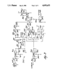
- FIG. 3 illustrates in detailed schematic form the circuits employed in the preferred embodiment of the present invention of power factor sensor 240.
- Power factor sensor 240 consists generally of a pair of signal conditioning units, one receiving the current signal from toroidal coil 245 and one receiving the secondary AC signal from the secondary of transformer 235, a phase comparison unit for comparing the phase of these two signals and a drive unit for activating a relay which provides the safety signal to motor controller 210.
- Operational amplifier 310 is the active element in the signal conditioner which is responsive to the signal from toroidal coil 245. This signal is applied to an input network including resistor 311 and a pair of diodes 312 and 313. Diodes 312 and 313 serve to limit the voltage applied to the inverting input of operational amplifier 310, thereby protecting this input.
- a feedback network including resistor 314 and resistor 315 controls the gain of operational amplifier 310.
- the output of operational amplifier 310 is a square wave having the same phase as the generally sinusoidal output of toroidal coil 245.
- the output of operational amplifier 310 is applied to a delay circuit including diode 326, capacitor 327 and a resistor network including resistor 321 and potentiometers 322 and 323.
- the switching contacts 324 of relay 325 selects one of these potentiometers 322 and 323 in a manner that will be more fully described below.
- This time delay circuit operates as follows: the output of operational amplifier 310 is generally a square wave having the same phase relationship as the current signal sensed by toroidal coil 245.
- diode 326 When the output of operational amplifier 310 is positive and above the voltage stored in capacitor 327, diode 326 is forward biased. This causes charge to be stored in capacitor 327 until the voltage across capacitor 327 equals the output voltage of operational amplifier 310. At this point diode 326 becomes back biased and no longer carries a current to charge capacitor 327. Because this is a low impedance path from the output of operational amplifier 310 to capacitor 327, the voltage in capacitor 327 quickly reaches the output voltage of operational amplifier 310, less the forward bias voltage drop across diode 326.
- the AND gate 330 is employed in a circuit to detect whether motor 30 is being supplied with electric power.
- the output of operational amplifier 310 is generally a square wave having the same phase relationship as the current sensed by toroidal coil 345. This output is applied to both inputs of AND gate 330 via a filter circuit comprising capacitor 331 and resistor 332. This filter circuit serves to delay and soften the rise time and fall times of the output from operational amplifier 310.
- a positive output AND gate 330 also generates a positive output. This serves to forward bias diode 333 and charge capacitor 336 via resistor 334.
- AND gate 370 is enabled when power is continuously supplied to motor 30, but is disabled when the power stops.
- Operational amplifier 340 is connected as a signal conditioning circuit to the secondary of transformer 235. This circuit is generally the same as previously described in conjunction with operational amplifier 330.
- the secondary AC signal is applied to the inverting input of operational amplifier 340 via resistor 341.
- Diodes 342 and 343 protect this input from over voltage conditions.
- a feedback circuit comprising resistors 344 and 345 is employed to set the gain of operational amplifier 340.
- the output of operational amplifier 340 is generally a square wave having the same phase as the secondary AC signal coming from transformer 235.
- exclusive OR circuit 350 The phase comparison between the current and voltage signals occurs in exclusive OR circuit 350.
- One input of exclusive OR circuit 350 is the output of operational amplifier 340, representing the voltage applied to motor 30.
- the other input comes from exclusive OR circuit 351 via resistor 352, corresponding to the current supplied to motor 30.
- a clamp circuit comprising AND gates 353 and 355 generally prevents the leading edge of the current signal from preceding the leading edge of the voltage signal. Ignoring for the moment the effect of the phase circuit including exclusive OR gates 361 and 362, assume that the output of exclusive OR gate 361 is a digital "0" and the output of exclusive OR gate 362 is a digital "1.”
- the digital "1" applied to the second input of exclusive OR gate 351 causes the extended current signal to be provided to exclusive OR gate 350 in the normal sense.
- AND gate 353 is enabled and AND gate 355 is disabled.
- the output of exclusive OR gate 351 becomes high prior to the output of operational amplifier 340 becoming high. This tends to cause a current to flow between the output of exclusive OR gate 351, via resistor 352, diode 358 and resistor 356 through the output of AND gate 355. Because AND gate 355 is disabled this output serves as a current sink.
- a second current path occurs from the output of exclusive OR gate 362 through diode 357 and resistor 356 to the current sink at the output of AND gate 355.
- the relative resistances of resistors 352 and 356 are selected so that the voltage divider circuit formed by these resistors applies a voltage to the input of exclusive OR gate 350 below the switching threshold of exclusive OR gate 350.
- exclusive OR gate 350 is not switched by this output of exclusive OR gate 351.
- this enables AND gate 353.
- This enables an additional current path from the output of OR gate 353, through diode 354, diode 358, resistor 356 into the current sink of OR gate 355. Because the current through resistor 352 is consequently reduced, the voltage applied to the input of exclusive OR gate 350 is thereby above the switching threshold of exclusive OR gate 350.
- exclusive OR gate 351 The leading edge of the current signal from exclusive OR gate 351 is similarly clamped to the leading edge of the voltage signal to operational amplifier 340 in the case of the opposite phase signal.
- exclusive OR gate 361 generates a digital "1"
- exclusive OR gate 362 generates a digital "0.”
- AND gate 353 is disabled and AND gate 355 is enabled.
- the provision of the low signal to one the second input of exclusive OR gate 351 serves to invert the signal from the current signal conditioning circuit including operational amplifier 310. If the output from exclusive OR gate 351 is high, then the current path is established from the output of exclusive OR gate 351, through resistor 352, diode 358 and resistor 356 into the current sink of the output of AND gate 355.
- exclusive OR gate 350 is not switched. However, when the output from operational amplifier 340 becomes high, AND gate 355 is switched on. This causes the output of AND gate 355 to supply voltage to resistor 356. Consequently, diode 358 is back biased and the voltage applied to the input of exclusive OR gate 350 rises to above the threshold level. The consequence of this circuit is that the exclusive OR circuit 350 does not switch on the leading edge of the current and voltage signals, which are clamped together but only switches on their trailing edges.
- phase signal is applied to this phase comparison circuit from exclusive OR gates 361 and 362.
- the direction of routing of the line from motor controller 210 to motor 30 determines the phase of the signal sensed by toroidal coil 345.
- the phase signal at the output of operational amplifier 310 would be displaced by 180 degrees.
- the phase detection circuit including exclusive OR gate 350 is set up to operate properly on one phase. If the phase of the current signal is shifted by 180 degrees, exclusive OR circuit 350 will always generate the safety signal and the automatic portal operator will not operate.
- exclusive OR gate 362 receives either a signal corresponding to the positive voltage or a ground signal depending upon the position of phase switch 363. In a first position, a high output is applied to the second input of exclusive OR circuit 351 and the current signal is passed unchanged. In the second position, a low input is applied to exclusive OR gate 351 and the current signal is inverted.
- a second exclusive OR gate 361 is similarly connected in an opposing relationship. As explained above, exclusive OR gate 361 controls the enabling of AND gate 355 which is concerned with the clamping circuit. It is proposed that the combination of motor controller 210 and power factor sensor 240 be tested and the phase switch 363 selected to the position which enables operation of motor 30.
- An additional circuit inverts the phase signal output from exclusive OR gates 361 and 362 upon motor reversal.
- Resistor 364 and capacitor 366 form a circuit which supplies a voltage signal to a second input of each of the exclusive OR gates 361 and 362. Under ordinary conditions the voltage across capacitor 366 is charged to above the voltage threshold level of the inputs of exclusive OR gates 361 and 362. As a consequence, the output of exclusive OR gates 361 and 362 is unchanged.
- the relay coil 368 is energized via the reverse signal from motor controller 210. This serves to close normally opened relay contacts 367. Closure of normally opened relay contacts 367 discharges the charge on capacitor 366.
- the output circuit of power factor sensor 240 includes AND gate 370.
- One input of AND gate 370 comes from the operation detection circuit including AND gate 330, which has been previously described.
- the other input of AND gate 370 comes from the output of exclusive OR gate 350.
- exclusive OR gate 350 generates a signal only when the trailing edges of the current signal and the voltage signal do not match. This output is applied to an RC circuit including resistor 371 and capacitor 372. This RC circuit serves as a glitch filter to absorb small signals from exclusive OR gate 350.
- a high output from exclusive OR gate 350 begins to charge capacitor 372 through resistor 371. If this high signal is of a relatively short duration, the voltage across capacitor 372 will not reach the threshold voltage at the input of AND gate 370.
- AND gate 370 will not be triggered.
- the output of exclusive OR gate is of sufficient duration, the voltage applied to the input of AND gate 370 will rise above the switching threshold. At this time, a high output is generated at the output of AND gate 370.
- This output serves two purposes. Firstly, this output forward biases diode 373 and serves to charge capacitor 372 to above the switching threshold. This serves to latch the output of AND gate 370 in order to provide sufficient time for operation of relay coil 383.
- the second result of the high output of AND gate 370 is the forward biasing of transistor 380 via resistor 381. This causes transistor 380 to conduct and actuate relay coil 383.
- Relay coil 383 has contacts (not shown) which ar connected to motor controller 210 to provide the safety signal to motor controller 210.
- Light emitting diode 384 is also energized through current limiting resistor 385. In accordance with the preferred embodiment, light emitting diode 384 is visible from the exterior of the automatic portal to indicate the generation of this safety signal.
- Diode 382 is always back biased during normal operation and serves to absorb the voltage spike caused by collapse of the magnetic field when the current through relay coil 383 is switched OFF.
- FIG. 4 illustrates a plurality of waveforms which will be used to explain the operation of the present invention.
- FIG. 4a illustrates the voltage signal 410 which is generated at the output of operational amplifier 340.
- FIG. 4b illustrates current signal 420 which is generated at the output of operational amplifier 310. Notice that current signal 420 has a leading phase in relationship to voltage signal 410 as indicated by 425 in FIG. 4b.
- FIG. 4c illustrates the waveform 430 which is the current signal input to exclusive OR gate 350. As explained above in relation to the description of FIG. 3, the leading edge of signal 430 is clamped to the leading edge of signal 410. Therefore, this leading edge of signal 430 does not differ from the leading edge of signal 410.
- FIG. 4a illustrates the voltage signal 410 which is generated at the output of operational amplifier 340.
- FIG. 4b illustrates current signal 420 which is generated at the output of operational amplifier 310. Notice that current signal 420 has a leading phase in relationship to voltage signal 410 as indicated by 425
- FIG. 4c illustrates a portion 435 of the pulse of signal 430 in hash marks.
- This portion of signal 430 represents the delay introduced by the delay circuit described above.
- the length 437 of this delay can be altered by changing the set point of the selected potentiometer 322 or 323.
- FIG. 4d illustrates signal 440 which is the output of exclusive OR gate 350.
- Exclusive OR gate 350 generates a signal only when the voltage signal 410 and the current signal 430 differ. Note that at the leading edge of voltage signal 410 no signal is generated because these leading edges are clamped together. In a practical embodiment of the present invention, there may in fact be a slight difference between these leading edges enabling a very short pulse at this time, which will not be of any consequence due to the filter composed of resistor 371 and capacitor 372. Note that at the trailing edge of voltage signal 410 and current signal 430, a short pulse 445 is generated.
- This short pulse 445 may be generated when the trailing edge of current signal 430 occurs after the trailing edge of voltage signal 410 (as illustrated herein) or may also occur when the trailing edge of current signal 430 precedes the trailing edge of current signal 410.
- the essential feature is that the set point of the selected potentiometer 322 or 323 is selected so that length of time 437 of the delay causes the trailing edge of current signal 430 to be near the trailing edge of voltage signal 410. Because this pulse 445 is so short, there is insufficient time for capacitor 372 to be charged to the threshold voltage of the input of AND gate 370. As a consequence, no safety signal is generated by power factor sensor 240.
- FIG. 4e illustrates a second current signal 450 having a smaller phase difference 455 from that of voltage signal 410. Such a smaller phase difference indicates operation in a more resistive mode, and consequently indicates the presence of a greater load on the motor 30.
- FIG. 4f illustrates the equivalent signal 460 applied to the input of exclusive OR gate 350.
- This signal also includes portion 465 corresponding to the delay caused by the delay circuit attached to operational amplifier 310.
- the interval 467 of this delay is equal to the interval 437 of the previously illustrated delay in FIG. 4c, because this potentiometer has not been adjusted.
- FIG. 4g illustrates output 470 from exclusive OR gate 350. Notice that because of the decrease of the amount of leading phase of the current signal in regard to the voltage signal, a much longer pulse 475 is generated at the output of exclusive OR gate 350. Also note, as previously illustrated in FIG. 4d, no output is generated at the leading edge of voltage signal 410. Because of this increase in the length of the output pulse to the size 475 illustrated in FIG. 4g, sufficient charge is accumulated on capacitor 372 to cause AND gate 370 to be enabled. As a consequence, relay coil 383 is energized and the safety signal is communicated to motor controller 210.
- FIG. 3 illustrates relay coil 325 which is energized from the reverse signal from motor controller 310.
- Relay contacts 324 selects one of the potentiometers 322 or 323.
- This provision of the time delay circuit enables the selection of a differing potentiometer setting for forward and reverse operations of the portal operator.
- a differing time delay can be set for forward and reverse operations and therefore a differing predetermined power factor threshold can be set for generation of the safety signal.
Abstract
Description
Claims (11)
Priority Applications (1)
| Application Number | Priority Date | Filing Date | Title |
|---|---|---|---|
| US07/163,862 US4855653A (en) | 1988-03-03 | 1988-03-03 | Obstruction detection in automatic portal control apparatus employing induction motor power factor |
Applications Claiming Priority (1)
| Application Number | Priority Date | Filing Date | Title |
|---|---|---|---|
| US07/163,862 US4855653A (en) | 1988-03-03 | 1988-03-03 | Obstruction detection in automatic portal control apparatus employing induction motor power factor |
Publications (1)
| Publication Number | Publication Date |
|---|---|
| US4855653A true US4855653A (en) | 1989-08-08 |
Family
ID=22591905
Family Applications (1)
| Application Number | Title | Priority Date | Filing Date |
|---|---|---|---|
| US07/163,862 Expired - Fee Related US4855653A (en) | 1988-03-03 | 1988-03-03 | Obstruction detection in automatic portal control apparatus employing induction motor power factor |
Country Status (1)
| Country | Link |
|---|---|
| US (1) | US4855653A (en) |
Cited By (28)
| Publication number | Priority date | Publication date | Assignee | Title |
|---|---|---|---|---|
| US5083397A (en) * | 1989-11-27 | 1992-01-28 | Ohi Seisakusho Co., Ltd. | Automatic door operating system |
| US5343266A (en) * | 1992-03-24 | 1994-08-30 | Eastman Kodak Company | Film extraction unit |
| US5341597A (en) * | 1993-01-22 | 1994-08-30 | Stoltenberg Donald A | Power operated garage door |
| FR2705392A1 (en) * | 1993-05-13 | 1994-11-25 | Aes | Unit and device for the opening and closing of doors |
| US5396158A (en) * | 1993-05-20 | 1995-03-07 | General Motors Corporation | Power vehicle door with reversal control |
| US5483133A (en) * | 1993-03-25 | 1996-01-09 | Mazda Motor Corporation | Control system for opening or closing an opening-closing member |
| US5581944A (en) * | 1993-07-08 | 1996-12-10 | The Stanley Works | Electrical link and sensor system for automatic sliding doors |
| US5747954A (en) * | 1997-01-30 | 1998-05-05 | Union Switch & Signal Inc. | Highway crossing guard mechanism controller |
| US5770934A (en) * | 1994-05-02 | 1998-06-23 | Dorma Gmbh & Co. Kg | Method for the closed-loop control of an automatic door which is propelled by a drive motor |
| US5838126A (en) * | 1995-05-22 | 1998-11-17 | Faiveley Transport | Method and apparatus for opening or closing a door by measuring the instantaneous voltage and current in an associated motor |
| US5929580A (en) * | 1997-08-05 | 1999-07-27 | Wayne-Dalton Corp. | System and related methods for detecting an obstruction in the path of a garage door controlled by an open-loop operator |
| US5982133A (en) * | 1995-07-28 | 1999-11-09 | Matsushita Electric Industrial Co., Ltd. | Brushless motor with rotor position detection compensation caused by induced voltage in rotor |
| USRE36428E (en) * | 1994-12-05 | 1999-12-07 | Chrysler Corporation | Automotive vehicle body with powered sliding side door |
| US6097166A (en) * | 1995-06-06 | 2000-08-01 | The Chamberlain Group, Inc. | Movable barrier having force and position learning capability |
| US6104156A (en) * | 1998-06-16 | 2000-08-15 | Somfy | Device for controlling the stopping of a motorized shrouding product |
| US6118243A (en) * | 1999-04-07 | 2000-09-12 | Overhead Door Corporation | Door operator system |
| US6326751B1 (en) | 1999-08-25 | 2001-12-04 | Wayne-Dalton Corp. | System and related methods for detecting and measuring the operational parameters of a garage door utilizing a lift cable system |
| US6346786B1 (en) * | 1999-08-12 | 2002-02-12 | Linear Millenium Products, Inc. | System and method for moving a horizontally movable portal closure |
| US20020101210A1 (en) * | 1992-04-22 | 2002-08-01 | Nartron Corporation | Collision monitoring system |
| US6435600B1 (en) | 1999-12-21 | 2002-08-20 | Daimlerchrysler Corporation | Method for operating a vehicle power sliding door |
| US20020113602A1 (en) * | 2001-02-22 | 2002-08-22 | Hidenori Ishihara | Pinched object detection apparatus for detecting object pinched by automatic door |
| US6507160B2 (en) | 1999-08-12 | 2003-01-14 | Linear Millenium Products, Inc. | Horizontally movable portal closure system |
| US6597138B2 (en) | 2001-08-01 | 2003-07-22 | The Chamberlain Group, Inc. | Method and apparatus for controlling power supplied to a motor |
| US20040183493A1 (en) * | 1992-04-22 | 2004-09-23 | Nartron Corporation | Collision monitoring system |
| US20070290645A1 (en) * | 2006-06-02 | 2007-12-20 | Boyadjieff George I | Method, system, and apparatus for controlling an electric motor |
| US7405530B2 (en) | 2001-11-30 | 2008-07-29 | The Chamberlain Group, Inc. | Method and apparatus for automatically establishing control values for a control device |
| US8176677B1 (en) * | 2008-02-27 | 2012-05-15 | Blackmon Iii Baron H | Automated guide rail apparatus |
| US8375635B2 (en) | 2009-08-26 | 2013-02-19 | Richard Hellinga | Apparatus for opening and closing overhead sectional doors |
Citations (6)
| Publication number | Priority date | Publication date | Assignee | Title |
|---|---|---|---|---|
| US3600657A (en) * | 1970-06-17 | 1971-08-17 | Jeanne Pfaff | Method and apparatus for electronic sensing of motor torque |
| US4335339A (en) * | 1979-11-20 | 1982-06-15 | Brickner Joseph L | Electronic safety device |
| US4394607A (en) * | 1981-05-08 | 1983-07-19 | Stanley Automatic Openers | Control systems for gates and the like including a motor overload monitoring circuit |
| GB2128425A (en) * | 1982-10-08 | 1984-04-26 | Newelec Pretoria | Stall detection apparatus |
| US4454462A (en) * | 1980-10-20 | 1984-06-12 | Neha International | Power factor motor controller |
| US4710692A (en) * | 1986-10-16 | 1987-12-01 | Square D Company | Self calibration of the thyristor firing angel of a motor controller using a current window to determine a final value of a reference current lag phase angle |
-
1988
- 1988-03-03 US US07/163,862 patent/US4855653A/en not_active Expired - Fee Related
Patent Citations (6)
| Publication number | Priority date | Publication date | Assignee | Title |
|---|---|---|---|---|
| US3600657A (en) * | 1970-06-17 | 1971-08-17 | Jeanne Pfaff | Method and apparatus for electronic sensing of motor torque |
| US4335339A (en) * | 1979-11-20 | 1982-06-15 | Brickner Joseph L | Electronic safety device |
| US4454462A (en) * | 1980-10-20 | 1984-06-12 | Neha International | Power factor motor controller |
| US4394607A (en) * | 1981-05-08 | 1983-07-19 | Stanley Automatic Openers | Control systems for gates and the like including a motor overload monitoring circuit |
| GB2128425A (en) * | 1982-10-08 | 1984-04-26 | Newelec Pretoria | Stall detection apparatus |
| US4710692A (en) * | 1986-10-16 | 1987-12-01 | Square D Company | Self calibration of the thyristor firing angel of a motor controller using a current window to determine a final value of a reference current lag phase angle |
Cited By (42)
| Publication number | Priority date | Publication date | Assignee | Title |
|---|---|---|---|---|
| US5083397A (en) * | 1989-11-27 | 1992-01-28 | Ohi Seisakusho Co., Ltd. | Automatic door operating system |
| US5343266A (en) * | 1992-03-24 | 1994-08-30 | Eastman Kodak Company | Film extraction unit |
| US20090272035A1 (en) * | 1992-04-22 | 2009-11-05 | Nartron Corporation | Collision monitoring system |
| US7548037B2 (en) * | 1992-04-22 | 2009-06-16 | Nartron Corporation | Collision monitoring system |
| US7579802B2 (en) * | 1992-04-22 | 2009-08-25 | Nartron Corporation | Collision monitoring system |
| US9030144B2 (en) | 1992-04-22 | 2015-05-12 | Uusi, Llc | Monitoring system |
| US20020101210A1 (en) * | 1992-04-22 | 2002-08-01 | Nartron Corporation | Collision monitoring system |
| US20040183493A1 (en) * | 1992-04-22 | 2004-09-23 | Nartron Corporation | Collision monitoring system |
| US8217612B2 (en) | 1992-04-22 | 2012-07-10 | Uusi, Llc | Collision monitoring system |
| US5341597A (en) * | 1993-01-22 | 1994-08-30 | Stoltenberg Donald A | Power operated garage door |
| US5483133A (en) * | 1993-03-25 | 1996-01-09 | Mazda Motor Corporation | Control system for opening or closing an opening-closing member |
| FR2705392A1 (en) * | 1993-05-13 | 1994-11-25 | Aes | Unit and device for the opening and closing of doors |
| US5396158A (en) * | 1993-05-20 | 1995-03-07 | General Motors Corporation | Power vehicle door with reversal control |
| US5581944A (en) * | 1993-07-08 | 1996-12-10 | The Stanley Works | Electrical link and sensor system for automatic sliding doors |
| US5770934A (en) * | 1994-05-02 | 1998-06-23 | Dorma Gmbh & Co. Kg | Method for the closed-loop control of an automatic door which is propelled by a drive motor |
| USRE36428E (en) * | 1994-12-05 | 1999-12-07 | Chrysler Corporation | Automotive vehicle body with powered sliding side door |
| US5838126A (en) * | 1995-05-22 | 1998-11-17 | Faiveley Transport | Method and apparatus for opening or closing a door by measuring the instantaneous voltage and current in an associated motor |
| US6806665B2 (en) | 1995-06-06 | 2004-10-19 | The Chamberlain Group, Inc. | Movable barrier operator having force and position learning capability |
| US6528961B1 (en) | 1995-06-06 | 2003-03-04 | The Chamberlain Group, Inc. | Movable barrier operator having force and position learning capability |
| US6310451B1 (en) | 1995-06-06 | 2001-10-30 | The Chamberlain Group, Inc. | Movable barrier operator having force and position learning capability |
| US6340872B1 (en) | 1995-06-06 | 2002-01-22 | The Chamberlain Group, Inc. | Movable barrier operator having force and position learning capability |
| US6097166A (en) * | 1995-06-06 | 2000-08-01 | The Chamberlain Group, Inc. | Movable barrier having force and position learning capability |
| US6107765A (en) * | 1995-06-06 | 2000-08-22 | The Chamberlain Group, Inc. | Movable barrier operator having force and position learning capability |
| US6111374A (en) * | 1995-06-06 | 2000-08-29 | The Chamberlain Group, Inc. | Movable barrier operator having force and position learning capability |
| US5982133A (en) * | 1995-07-28 | 1999-11-09 | Matsushita Electric Industrial Co., Ltd. | Brushless motor with rotor position detection compensation caused by induced voltage in rotor |
| US5747954A (en) * | 1997-01-30 | 1998-05-05 | Union Switch & Signal Inc. | Highway crossing guard mechanism controller |
| US5929580A (en) * | 1997-08-05 | 1999-07-27 | Wayne-Dalton Corp. | System and related methods for detecting an obstruction in the path of a garage door controlled by an open-loop operator |
| US6104156A (en) * | 1998-06-16 | 2000-08-15 | Somfy | Device for controlling the stopping of a motorized shrouding product |
| US6118243A (en) * | 1999-04-07 | 2000-09-12 | Overhead Door Corporation | Door operator system |
| US6507160B2 (en) | 1999-08-12 | 2003-01-14 | Linear Millenium Products, Inc. | Horizontally movable portal closure system |
| US6346786B1 (en) * | 1999-08-12 | 2002-02-12 | Linear Millenium Products, Inc. | System and method for moving a horizontally movable portal closure |
| US6326751B1 (en) | 1999-08-25 | 2001-12-04 | Wayne-Dalton Corp. | System and related methods for detecting and measuring the operational parameters of a garage door utilizing a lift cable system |
| US6588829B2 (en) | 1999-12-21 | 2003-07-08 | Daimlerchrysler Corporation | Method for operating a vehicle power sliding door |
| US6435600B1 (en) | 1999-12-21 | 2002-08-20 | Daimlerchrysler Corporation | Method for operating a vehicle power sliding door |
| US20020113602A1 (en) * | 2001-02-22 | 2002-08-22 | Hidenori Ishihara | Pinched object detection apparatus for detecting object pinched by automatic door |
| US7000352B2 (en) * | 2001-02-22 | 2006-02-21 | Asmo Co., Ltd. | Backdoor system of vehicle having pressure sensor for detecting object pinched by backdoor |
| US6597138B2 (en) | 2001-08-01 | 2003-07-22 | The Chamberlain Group, Inc. | Method and apparatus for controlling power supplied to a motor |
| US7405530B2 (en) | 2001-11-30 | 2008-07-29 | The Chamberlain Group, Inc. | Method and apparatus for automatically establishing control values for a control device |
| US7768221B2 (en) | 2006-06-02 | 2010-08-03 | Power Efficiency Corporation | Method, system, and apparatus for controlling an electric motor |
| US20070290645A1 (en) * | 2006-06-02 | 2007-12-20 | Boyadjieff George I | Method, system, and apparatus for controlling an electric motor |
| US8176677B1 (en) * | 2008-02-27 | 2012-05-15 | Blackmon Iii Baron H | Automated guide rail apparatus |
| US8375635B2 (en) | 2009-08-26 | 2013-02-19 | Richard Hellinga | Apparatus for opening and closing overhead sectional doors |
Similar Documents
| Publication | Publication Date | Title |
|---|---|---|
| US4855653A (en) | Obstruction detection in automatic portal control apparatus employing induction motor power factor | |
| US4408146A (en) | Automatic door operator | |
| US6570392B2 (en) | Arc fault circuit detector device detecting pulse width modulation of arc noise | |
| US5818237A (en) | Apparatus for envelope detection of low current arcs | |
| US5774319A (en) | Energy validation arrangement for a self-powered circuit interrupter | |
| US5455733A (en) | Contact status monitor | |
| US6590754B1 (en) | AFCI with false trip prevention filter | |
| WO1997018611A9 (en) | Energy validation arrangement for a self-powered circuit interrupter | |
| US20030099070A1 (en) | Arc fault circuit interrupter which detects the cessation of arcs of an arc fault | |
| CA2337446A1 (en) | Arc fault circuit interrupter recognizing arc noise burst patterns | |
| US3619723A (en) | Sensitive peak current detector for ground fault protection circuits | |
| TW201101630A (en) | Apparatus and method for protection of current sense resistor short circuit in isolated type power supply | |
| WO1985001773A1 (en) | Obstruction detection means | |
| US6211665B1 (en) | Solenoid motion detection circuit | |
| US5151638A (en) | Motor overload indicating arrangement | |
| US3662229A (en) | Automatic door control unit | |
| EP1322016A2 (en) | Arc fault detector immune to dimmer transients and a circuit breaker incorporating the same | |
| US4142137A (en) | Operator motor control | |
| CA3025101A1 (en) | Circuit interrupter providing grounded neutral protection and method of controlling the same | |
| WO1992020891A1 (en) | A motor reverse system | |
| US6160955A (en) | Control circuits of an apparatus for physical exercises | |
| GB2237658A (en) | Window winder | |
| US4477758A (en) | Stepping motor overcurrent detection and protection device | |
| EP0431705B1 (en) | Protected closing device | |
| US4220902A (en) | Electrical vehicle traction equipment |
Legal Events
| Date | Code | Title | Description |
|---|---|---|---|
| AS | Assignment |
Owner name: STANLEY AUTOMATIC OPENERS, DETROIT, MICHIGAN A COR Free format text: ASSIGNMENT OF ASSIGNORS INTEREST.;ASSIGNOR:LEMIRANDE, RODGER P.;REEL/FRAME:004855/0274 Effective date: 19880203 Owner name: STANLEY AUTOMATIC OPENERS, A CORP. OF MI.,MICHIGAN Free format text: ASSIGNMENT OF ASSIGNORS INTEREST;ASSIGNOR:LEMIRANDE, RODGER P.;REEL/FRAME:004855/0274 Effective date: 19880203 |
|
| FPAY | Fee payment |
Year of fee payment: 4 |
|
| FPAY | Fee payment |
Year of fee payment: 8 |
|
| AS | Assignment |
Owner name: WHISTLER CORPORATION OF MASSACHUSETTS, MASSACHUSET Free format text: ASSIGNMENT OF ASSIGNORS INTEREST;ASSIGNOR:STANLEY HOME AUTOMATION, INC.;REEL/FRAME:008366/0001 Effective date: 19970214 |
|
| AS | Assignment |
Owner name: STANLEY WORKS, THE, CONNECTICUT Free format text: SUBORDINATED SECURITY AGREEMENT;ASSIGNOR:WHISTLER CORPORATION OF MASSACHUSETTS;REEL/FRAME:008382/0950 Effective date: 19970214 Owner name: NATIONAL BANK OF CANADA, MASSACHUSETTS Free format text: SECURITY INTEREST;ASSIGNOR:WHISTLER CORPORATION OF MASSACHUSETTS;REEL/FRAME:008382/0177 Effective date: 19970214 Owner name: HSN MARKETING, INC., NEW JERSEY Free format text: SUBORDINATED SECURITY AGREEMENT;ASSIGNOR:WHISTLER CORPORATION OF MASSACHUSETTS;REEL/FRAME:008354/0967 Effective date: 19970214 |
|
| AS | Assignment |
Owner name: STANLEY HOME AUTOMATION, INC., MICHIGAN Free format text: CHANGE OF NAME;ASSIGNOR:STANLEY AUTOMATIC OPENERS, INC.;REEL/FRAME:008613/0561 Effective date: 19880408 |
|
| AS | Assignment |
Owner name: MOORE-O-MATIC, INC., CALIFORNIA Free format text: ASSIGNMENT OF ASSIGNORS INTEREST;ASSIGNOR:WHISTLER CORPORATION OF MASSACHUSETTS;REEL/FRAME:008783/0340 Effective date: 19971015 |
|
| REMI | Maintenance fee reminder mailed | ||
| LAPS | Lapse for failure to pay maintenance fees | ||
| FP | Lapsed due to failure to pay maintenance fee |
Effective date: 20010808 |
|
| STCH | Information on status: patent discontinuation |
Free format text: PATENT EXPIRED DUE TO NONPAYMENT OF MAINTENANCE FEES UNDER 37 CFR 1.362 |