US4811550A - Method and device for manufacturing and positioning upon a container an undercut thermoplastic lid, and container provided with such a lid - Google Patents
Method and device for manufacturing and positioning upon a container an undercut thermoplastic lid, and container provided with such a lid Download PDFInfo
- Publication number
- US4811550A US4811550A US07/066,980 US6698087A US4811550A US 4811550 A US4811550 A US 4811550A US 6698087 A US6698087 A US 6698087A US 4811550 A US4811550 A US 4811550A
- Authority
- US
- United States
- Prior art keywords
- container
- bell
- support
- lid
- edge
- Prior art date
- Legal status (The legal status is an assumption and is not a legal conclusion. Google has not performed a legal analysis and makes no representation as to the accuracy of the status listed.)
- Expired - Fee Related
Links
Images


Classifications
-
- B—PERFORMING OPERATIONS; TRANSPORTING
- B65—CONVEYING; PACKING; STORING; HANDLING THIN OR FILAMENTARY MATERIAL
- B65B—MACHINES, APPARATUS OR DEVICES FOR, OR METHODS OF, PACKAGING ARTICLES OR MATERIALS; UNPACKING
- B65B7/00—Closing containers or receptacles after filling
- B65B7/16—Closing semi-rigid or rigid containers or receptacles not deformed by, or not taking-up shape of, contents, e.g. boxes or cartons
- B65B7/162—Closing semi-rigid or rigid containers or receptacles not deformed by, or not taking-up shape of, contents, e.g. boxes or cartons by feeding web material to securing means
- B65B7/167—Securing by heat-shrinking
Definitions
- the present invention relates to a method and device for manufacturing and positioning upon a container an undercut thermoplastic lid, and to a container provided with such a lid.
- thermoplastic lids and in particular lids destined to act, first as an over-lid covering over the lid sheet sealed on the container, and then as a permanent lid after the destruction of the lid sheet, are prefabricated by thermoforming in a thermoplastic band, with a mold of suitable shape, and are thereafter cut from the thermoplastic band before being fixed on the corresponding containers by screwing or snap-fitting.
- the dimensions of these lids vary from one batch of lids to another. Variations in the dimensions may be due to the use of different basic materials having different degrees of shrinkage. Furthermore, the dimensions of the edges of the thermoplastic containers are also prone to variations. It has been found that wear of the equipment used for producing the lids and the containers and for cutting them, also contributes to such variations in the dimensions. It has also proved difficult to correctly center the prefabricated lids with respect to the edge of the containers.
- thermoplastic band In a method for manufacturing a lid from a thermoplastic band, using a forming bell, a holding clamp for clamping an annular area of the thermoplastic band against the lower annular edge of the forming bell, and a stamping die or male forming mold, located inside the volume defined by said bell and pushing the part of band delimited by said bell, this object is reached according to the invention due to the fact that the upper part of the container support as well as the upper part of the container which extends from the upper end of said container support are used as stamping die or male forming mold, and the part of thermoplastic band defined by the lower edge of the bell is applied against the outer face of the upper parts of the container and of its support under a gas excess pressure created inside an enclosure closed and defined by the bell and the thermoplastic band.
- the lid or over-lid takes on the exact the shape of the upper end of the container and is already fitted over it at the end of the thermoforming operation.
- the lid molded on the container and the upper part of the container support is cut from the thermoplastic band while it is still under the forming bell.
- This step eliminates the need of re-centering the container and the over-molded lid with respect to a cutting tool.
- the device for manufacturing and positioning an undercut thermoplastic lid which comprises a forming bell provided with a lower annular edge and connections with a source of pressurized gas,and a lower holding clamp adapted to apply an annular area of a preheated thermoplastic band against the lower face of said lower annular edge, is characterized in that it comprises, under the bell and inside the inner periphery of the lower edge thereof, an annular container support of which the upper part, which is partly overhung by the upper end of the container, also acts as a stamping die or male forming mold for the marginal part of the lid to be thermoformed.
- thermoformed lid is automatically adapted to the shape of the container to be covered.
- FIG. 1 is an elevational view of an axial vertical section through the device for manufacturing and positioning a thermoplastic lid, the different elements of the device being in a position ready for thermoforming;
- FIG. 2 is an elevational view similar to FIG. 1, but showing the different elements of the device in a position in which the lid is already partly formed;
- FIG. 3 is an elevational view similar to FIGS. 1 and 2 but showing the different elements of the device in the position in which the lid is completely thermoformed on the container and cut from the thermoplastic band;
- FIG. 4 is a diagrammatical perspective view of the container support forming part of the device according to the invention.
- FIGS. 5 to 7 are elevational views of several vertical cross-sections of the container support taken along lines V--V, VI--VI and VII--VII of FIG. 4;
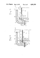
- FIG. 8 is an elevational view through a number of elements of a device according to the invention, cooperating with a container of which the upper end is threaded;
- FIG. 9 is an elevational view of an axial section through a container equipped with a lid by means of the device according to FIG. 8;
- FIG. 10 shows a container support and its corresponding container for the production of an inviolable lid
- FIG. 11 shows a plan view of one detail of the lid according to FIG. 10.
- the device for manufacturing and positioning an undercut thermoplastic lid comprises a forming bell 1 placed above the horizontal plane 2 defined by the horizontal path of a thermoplastic band 3 in which lids or overlids, also called undercut lids, will be thermoformed.
- the lower end of the forming bell has a widened annular edge 5 of which the lower face 5a is flat and horizontal and is used as a rest for an annular zone of the thermoplastic band 3 when said zone is applied against said lower face 5a by means of an annular holding clamp 6 provided under the horizontal plane 2 so as to be vertically movable between a high position in which it applies the thermoplastic band 3 against the edge 5 of the forming bell 1 and a lower position (illustrated in broken lines in FIG. 1) in which a container 7 can be brought laterally under the thermoplastic band 3 and the bell 1.
- the device according to the invention further comprises, under the thermoplastic band 3 and inside the inner periphery of the lower edge 5 of the bell 1, and consequently also inside the inner periphery of the holding clamp 6 which preferably coincides vertically with said lower edge 5, a container support 8 which comprises a housing receiving the container 7 and which supports said container 7, either by its upper lateral edge 8a (FIGS. 1 to 7), or by its lower end 8b (FIG. 8), or else by its upper edge 8a and its lower end 8b (FIG. 10).
- a container support 8 which comprises a housing receiving the container 7 and which supports said container 7, either by its upper lateral edge 8a (FIGS. 1 to 7), or by its lower end 8b (FIG. 8), or else by its upper edge 8a and its lower end 8b (FIG. 10).
- This container support 8 is also vertically movable between, first a high posiiton in which said support penetrates, at least by its upper part of which the outer face 8c has the shape of a skirt widening out downwardly and outwardly, as far as an annular shoulder 8d, thus constituting a stamping die or male forming mold inside the enclosure of the bell 1 (FIG. 2), and second, a low position (see FIG. 1, support in broken lines) in which a container 7 can be loaded laterally and through the top into container support 8.
- a support plate 9 which covers all the zone of the thermoplastic band 3 situated opposite the container 7 and defined by the upper edge 7a of the latter.
- the periphery of the upper end of container 7 normally coincides with the periphery of the support plate 9 placed above the horizontal plane 2 and more generally of the thermoplastic band 3.
- Said support plate 9 is vertically movable inside the bell 1 between, on the one hand, a high position in which the annular part 3a of the thermoplastic band 3, which part 3a is comprised between the lower edge 5 of the bell 1 or the corresponding clamping member 6 and the edge of the support plate 9 or the upper edge 7a of the container 7, is stretched (FIG. 2) with respect to its initial radial length (FIG.
- the lower face 9a of the support plate 9 is provided with an annular groove 9b of which the bottom is connected, via a plurality of suction channels 9c, to a vacuum pump, not shown.
- enclosure 11 defined by the forming bell 1 and the thermoplastic band 3 gripped between the lower edge 5 of the bell 1 and the holding clamp 6 (FIG. 1) is connected via a plurality of orifices 12 provided in the wall of bell 1, and via a control valve, with a source of pressurized gaseous fluid, both of which are not shown.
- the lid 4 is, in general, composed of an upper wall 4a and of a lateral skirt 4b which, depending on the shape of the upper end of containers 7, can have various configurations.
- the upper wall 4a of the lid 4 presents, in its marginal part, an annular reinforcing rib 4c obtained by suction of the thermoplastic material situated opposite the annular groove 9b which is connected with the suction channel 9c, which channels are in turn connected via a control valve to a vacuum pump.
- Said annular rib 4c is thermoformed when the thermoplastic band 3 is gripped between the edge 5 of the bell 1 and the holding clamp 6 and when the horizontal flat edge 7a of the container 7 and the corresponding part of the thermoplastic band preheated to the forming temperature are held between support plate 9 in low position and container support 8 in intermediate position (FIG. 1).
- the assembly consisting of the container support 8, the container 7, the part of thermoplastic band covering the upper end and in particular the upper edge 7a of said container, and the support plate 9, can also be moved upwardly until the lateral annular shoulder 8d of container support 8 reaches nearly to the level of the horizontal plane 2 of the thermoplastic band 3 and virtually closes off the base of the bell 1 at the level of the lower face 5a thereof (FIG. 2).
- the skirt-shaped outer face 8c of the upper part of the container support 8 has a vertical cylindrical upper part 8c' followed by a widening out lower part 8c" of truncated general shape which joins up with the near-horizontal annular lateral shoulder 8d.
- horizontal shoulder 8d is joined on its periphery with a vertical cylindrical wall 8e the periphery of which fits without noticeable lateral play inside the inner periphery of the lower edge 5 of the bell 1, on the one hand, and inside that of the holding clamp 6, on the other hand.
- thermoplastic band 3 gripped between the bell 1 and the holding clamp 6
- a pressurized gas such as compressed air
- the annular part 3a of the thermoplastic band 3 which part is situated between holding clamp 6 or edge 5 and the support plate 9 and is at the thermoforming temperature, against the edge 7a of container 7 and against the outer face or skirt 8c of the container support 8 where it will be immediately solidified under the cooling effect caused by its contacting with the cold container support 8.
- the lid 4 is thermoformed on the edge 7a of the container and on the outer face 8c of the upper part of the container support 8, it should be possible to eject the lid 4 together with the container 7 which is joined thereto due to the fact that at least certain parts 4d of the lid 4 are undercut-molded and are applied against part of the lower face of the horizontal edge 7a of the container. To this effect, it would be necessary to move respectively upwardly and downwardly first the bell 1 and the support plate 9, and second the holding clamp 6 and the container support 8, in order to transfer of one step the assembly composed of container 7, formed lid 4 and thermoplastic band 3 which, at this stage in the operation, is still attached to the formed lid 4. Then the lid 4 has to be cut from the thermoplastic band 3 in a separate cutting station.
- the annular shoulder 8d of the container support 8 is used as the cutting edge of a movable stamp and the inner edge of the lower end 5 of the bell 1 is used as the counter-cutting edge of a fixed stamping die which cooperates with the cutting edge of said stamp.
- the lid 4 is cut or stamped in the thermoplastic band 3 immediately after being formed, at the lower end of its skirt 4b when the annular shoulder 8d of container support 8 penetrates into enclosure 11 of the bell 1 and projects upwardly from the level of the lower face 5a of the lower edge 5 of the bell 1 (FIG. 3).
- the assembly consisting of container 7 and lid 4 can then be removed from the bell 1 in a conventional way, by lowering the holding clamp 6 and the container support 8 and removing the container 7.
- the upper part of the container support 8 therefore comprises only in a few areas predetermined as a function of the general shape of the container edge 7a, a thickness of wall such that its outer face 8c, and more precisely side face 8c' which joins up with the horizontal upper face 8a, is slightly set back, for example by 0.5 to 2 mm with respect to the vertical face of the container edge 7a when a container is placed into said container supports.
- Such areas permitting the production of an undercut are indicated in FIGS. 4 and 5 by reference 13 (see also cross-section along line V--V, FIGS. 4 and 5).
- the container support is provided, on its periphery, on the outside of upper horizontal face 8a and on the inside of annular shoulder 8d, with a number of vertical fingers or lugs 14 comprising at their free end 14a which projects of a few millimeters from upper horizontal face 8a of the container support 8, an inner centering face 14b which is more or less inclined, with respect to the vertical, from the top downwards and inwardly to the container support 8.
- thermoformed lid 4 shows no undercut, but only a lateral skirt 4b joining up directly with the horizontal part 4a of said lid 4.
- Said areas 15 without undercut can exist either between two adjacent centering fingers 14, or between one centering finger 14 and one undercut area 13, or else between two undercut areas 13.
- the number and position of the undercuts 4d of the lid 4 are determined as a function of the sizes and general configuration of said lid 4 and so that, in the case of a removable and re-usable lid, the snap fitting of the lid 4 on the edge of the container 7a can be performed easily, reliably and without permanent deformation to the lid.
- the device used for producing the lids 4, illustrated in FIGS. 9 and 10 has the same general structure as the device shown in FIG. 1, centering of the container 7 with respect to the container support 8 being achieved via the inner side wall 8f thereof.
- the lid 4 has no reinforcing rib and when, as a result, its upper horizontal face 4a is flat, the lower face 9a of support plate 9 is entirely plane and has no annular groove.
- container 7 is supported at its lower end by the lower part 8b of the container support 8 and projects by its coarsely threaded upper part 7c from the truncated upper face 8c of the container support 8, the outer lower part of which truncated face 8c coincides with the annular shoulder 8d which acts as a stamping edge with the die constituted by the lower edge 5 of the bell 1.
- annular shoulder 8d acts as a stamping edge with the die constituted by the lower edge 5 of the bell 1.
- thermoform the lid 4 with an undercut thread 15 by applying compressed air into enclosure 11 through orifices 12, and the lid can be cut immediately after being formed (FIG. 8).
- the molded lid 4 can then be removed from container 7 by destroying the connection of a small locking tab 16 fast with the container 7 at the level of the threaded part 7c, and by unscrewing the lid 4 (FIG. 9), the truncated skirt 4b being joined to the threaded part 15.
- the container support 8 comprises an annular horizontal upper face of small width 8a which fits under the container edge 7a which is wider than said horizontal face 8a and which projects laterally outwardly thereof, a truncated outer face 8c joining up with the horizontal face 8a of the container support 8.
- the truncated outer face 8c of the upper part of container support 8 acts as a male mold for forming the lid 4 and its lower edge equivalent to the annular shoulder 8d of the example illustrated in FIGS. 1 to 7, acts as a stamping edge in cooperation with the edge of the die constituted by the lower edge 5 of the bell 1.
- the molded lid is a lid which has a continuous annular undercut 4d so that said lid 4 can only be removed after partial destruction thereof.
- This type of lid is particularly adapted to act as inviolable lids.
Abstract
The present invention relates to a method for manufacturing and positioning upon a container, an undercut thermoplastic lid, made from a thermoplastic band.
According to the invention, in said method the upper part of the container support as well as the upper part of the container which extends from the upper end of said container support are used as stamping die or male forming mold, and the part of thermoplastic band defined by the lower edge of the bell is applied against the outer face of the upper parts of the container and of its support under a gas excess pressure created inside an enclosure closed and defined by the ball and the thermoplastic band.
Description
The present invention relates to a method and device for manufacturing and positioning upon a container an undercut thermoplastic lid, and to a container provided with such a lid.
Some of the conventional undercut thermoplastic lids, and in particular lids destined to act, first as an over-lid covering over the lid sheet sealed on the container, and then as a permanent lid after the destruction of the lid sheet, are prefabricated by thermoforming in a thermoplastic band, with a mold of suitable shape, and are thereafter cut from the thermoplastic band before being fixed on the corresponding containers by screwing or snap-fitting.
The dimensions of these lids vary from one batch of lids to another. Variations in the dimensions may be due to the use of different basic materials having different degrees of shrinkage. Furthermore, the dimensions of the edges of the thermoplastic containers are also prone to variations. It has been found that wear of the equipment used for producing the lids and the containers and for cutting them, also contributes to such variations in the dimensions. It has also proved difficult to correctly center the prefabricated lids with respect to the edge of the containers.
It is the object of the present invention to eliminate these disadvantages and to propose a method and device for manufacturing and positioning an undercut thermoplastic lid over a container which permit instant adaptation of the lid over the corresponding container without having to make allowance for the variations in dimensions compared with the containers average dimensions.
In a method for manufacturing a lid from a thermoplastic band, using a forming bell, a holding clamp for clamping an annular area of the thermoplastic band against the lower annular edge of the forming bell, and a stamping die or male forming mold, located inside the volume defined by said bell and pushing the part of band delimited by said bell, this object is reached according to the invention due to the fact that the upper part of the container support as well as the upper part of the container which extends from the upper end of said container support are used as stamping die or male forming mold, and the part of thermoplastic band defined by the lower edge of the bell is applied against the outer face of the upper parts of the container and of its support under a gas excess pressure created inside an enclosure closed and defined by the bell and the thermoplastic band.
Due to this concept, the lid or over-lid takes on the exact the shape of the upper end of the container and is already fitted over it at the end of the thermoforming operation.
According to another advantageous feature of the invention, the lid molded on the container and the upper part of the container support is cut from the thermoplastic band while it is still under the forming bell.
This step eliminates the need of re-centering the container and the over-molded lid with respect to a cutting tool.
The device for manufacturing and positioning an undercut thermoplastic lid which comprises a forming bell provided with a lower annular edge and connections with a source of pressurized gas,and a lower holding clamp adapted to apply an annular area of a preheated thermoplastic band against the lower face of said lower annular edge, is characterized in that it comprises, under the bell and inside the inner periphery of the lower edge thereof, an annular container support of which the upper part, which is partly overhung by the upper end of the container, also acts as a stamping die or male forming mold for the marginal part of the lid to be thermoformed.
Owing to this particular concept, the thermoformed lid is automatically adapted to the shape of the container to be covered.
The invention will be more readily understood on reading the following description with reference to the accompanying drawings in which:
FIG. 1 is an elevational view of an axial vertical section through the device for manufacturing and positioning a thermoplastic lid, the different elements of the device being in a position ready for thermoforming;
FIG. 2 is an elevational view similar to FIG. 1, but showing the different elements of the device in a position in which the lid is already partly formed;
FIG. 3 is an elevational view similar to FIGS. 1 and 2 but showing the different elements of the device in the position in which the lid is completely thermoformed on the container and cut from the thermoplastic band;
FIG. 4 is a diagrammatical perspective view of the container support forming part of the device according to the invention;
FIGS. 5 to 7 are elevational views of several vertical cross-sections of the container support taken along lines V--V, VI--VI and VII--VII of FIG. 4;
FIG. 8 is an elevational view through a number of elements of a device according to the invention, cooperating with a container of which the upper end is threaded;
FIG. 9 is an elevational view of an axial section through a container equipped with a lid by means of the device according to FIG. 8;
FIG. 10 shows a container support and its corresponding container for the production of an inviolable lid, and
FIG. 11 shows a plan view of one detail of the lid according to FIG. 10.
As illustrated in the drawings, the device for manufacturing and positioning an undercut thermoplastic lid comprises a forming bell 1 placed above the horizontal plane 2 defined by the horizontal path of a thermoplastic band 3 in which lids or overlids, also called undercut lids, will be thermoformed. The lower end of the forming bell has a widened annular edge 5 of which the lower face 5a is flat and horizontal and is used as a rest for an annular zone of the thermoplastic band 3 when said zone is applied against said lower face 5a by means of an annular holding clamp 6 provided under the horizontal plane 2 so as to be vertically movable between a high position in which it applies the thermoplastic band 3 against the edge 5 of the forming bell 1 and a lower position (illustrated in broken lines in FIG. 1) in which a container 7 can be brought laterally under the thermoplastic band 3 and the bell 1.
The device according to the invention further comprises, under the thermoplastic band 3 and inside the inner periphery of the lower edge 5 of the bell 1, and consequently also inside the inner periphery of the holding clamp 6 which preferably coincides vertically with said lower edge 5, a container support 8 which comprises a housing receiving the container 7 and which supports said container 7, either by its upper lateral edge 8a (FIGS. 1 to 7), or by its lower end 8b (FIG. 8), or else by its upper edge 8a and its lower end 8b (FIG. 10). This container support 8 is also vertically movable between, first a high posiiton in which said support penetrates, at least by its upper part of which the outer face 8c has the shape of a skirt widening out downwardly and outwardly, as far as an annular shoulder 8d, thus constituting a stamping die or male forming mold inside the enclosure of the bell 1 (FIG. 2), and second, a low position (see FIG. 1, support in broken lines) in which a container 7 can be loaded laterally and through the top into container support 8.
In the bell 1 is provided a support plate 9 which covers all the zone of the thermoplastic band 3 situated opposite the container 7 and defined by the upper edge 7a of the latter. Thus, the periphery of the upper end of container 7 normally coincides with the periphery of the support plate 9 placed above the horizontal plane 2 and more generally of the thermoplastic band 3. Said support plate 9 is vertically movable inside the bell 1 between, on the one hand, a high position in which the annular part 3a of the thermoplastic band 3, which part 3a is comprised between the lower edge 5 of the bell 1 or the corresponding clamping member 6 and the edge of the support plate 9 or the upper edge 7a of the container 7, is stretched (FIG. 2) with respect to its initial radial length (FIG. 1) or else is cut from the rest of the thermoplastic band 3 (FIG. 3), and on the other hand, a low position in which the lower face 9a of the support plate 9 is situated on the level of the lower horizontal face 5a of the lower edge 5 of bell 1 (FIG. 1). The vertical movement of the support plate 9 is controlled by means of a rod 10, fast with the upper face of support plate 9, traversing in tight manner the upper wall 1a of the bell 1 and connected to the piston of a control jack not shown. The forming bell 1 can, if required, move vertically of a few millimeters or more in order to clear the moving path of the thermoplastic band 3 as long as this path is situated under the bell 1. In other cases, the bell 1 can be fixedly mounted.
Above the container edge 7a, and more particularly opposite the upper end 8a of the container support 8, the lower face 9a of the support plate 9 is provided with an annular groove 9b of which the bottom is connected, via a plurality of suction channels 9c, to a vacuum pump, not shown. On the contrary, enclosure 11 defined by the forming bell 1 and the thermoplastic band 3 gripped between the lower edge 5 of the bell 1 and the holding clamp 6 (FIG. 1) is connected via a plurality of orifices 12 provided in the wall of bell 1, and via a control valve, with a source of pressurized gaseous fluid, both of which are not shown.
The lid 4 is, in general, composed of an upper wall 4a and of a lateral skirt 4b which, depending on the shape of the upper end of containers 7, can have various configurations.
According to a first embodiment, the upper wall 4a of the lid 4 presents, in its marginal part, an annular reinforcing rib 4c obtained by suction of the thermoplastic material situated opposite the annular groove 9b which is connected with the suction channel 9c, which channels are in turn connected via a control valve to a vacuum pump. Said annular rib 4c is thermoformed when the thermoplastic band 3 is gripped between the edge 5 of the bell 1 and the holding clamp 6 and when the horizontal flat edge 7a of the container 7 and the corresponding part of the thermoplastic band preheated to the forming temperature are held between support plate 9 in low position and container support 8 in intermediate position (FIG. 1). Obviously, throughout the forming of the reinforcing rib 4c of the lid 4, the assembly consisting of the container support 8, the container 7, the part of thermoplastic band covering the upper end and in particular the upper edge 7a of said container, and the support plate 9, can also be moved upwardly until the lateral annular shoulder 8d of container support 8 reaches nearly to the level of the horizontal plane 2 of the thermoplastic band 3 and virtually closes off the base of the bell 1 at the level of the lower face 5a thereof (FIG. 2).
In the particular embodiment illustrated in vertical section in FIGS. 1 to 3, the skirt-shaped outer face 8c of the upper part of the container support 8 has a vertical cylindrical upper part 8c' followed by a widening out lower part 8c" of truncated general shape which joins up with the near-horizontal annular lateral shoulder 8d.
In general, horizontal shoulder 8d is joined on its periphery with a vertical cylindrical wall 8e the periphery of which fits without noticeable lateral play inside the inner periphery of the lower edge 5 of the bell 1, on the one hand, and inside that of the holding clamp 6, on the other hand. When the container support 8 is in the position illustrated in FIG. 2, in which shoulder 8d is just below the level of the thermoplastic band 3 gripped between the bell 1 and the holding clamp 6, it is possible to use the upper part 8c of the container support 8 as a molding die by feeding a pressurized gas, such as compressed air, into the enclosure 11 of the bell, through orifices 12, thereby applying the annular part 3a of the thermoplastic band 3, which part is situated between holding clamp 6 or edge 5 and the support plate 9 and is at the thermoforming temperature, against the edge 7a of container 7 and against the outer face or skirt 8c of the container support 8 where it will be immediately solidified under the cooling effect caused by its contacting with the cold container support 8.
Once the lid 4 is thermoformed on the edge 7a of the container and on the outer face 8c of the upper part of the container support 8, it should be possible to eject the lid 4 together with the container 7 which is joined thereto due to the fact that at least certain parts 4d of the lid 4 are undercut-molded and are applied against part of the lower face of the horizontal edge 7a of the container. To this effect, it would be necessary to move respectively upwardly and downwardly first the bell 1 and the support plate 9, and second the holding clamp 6 and the container support 8, in order to transfer of one step the assembly composed of container 7, formed lid 4 and thermoplastic band 3 which, at this stage in the operation, is still attached to the formed lid 4. Then the lid 4 has to be cut from the thermoplastic band 3 in a separate cutting station.
In certain cases however, it is more advantageous to provide such cutting station in exactly the same working station as the bell 1. To this effect, the annular shoulder 8d of the container support 8 is used as the cutting edge of a movable stamp and the inner edge of the lower end 5 of the bell 1 is used as the counter-cutting edge of a fixed stamping die which cooperates with the cutting edge of said stamp. In this way, the lid 4 is cut or stamped in the thermoplastic band 3 immediately after being formed, at the lower end of its skirt 4b when the annular shoulder 8d of container support 8 penetrates into enclosure 11 of the bell 1 and projects upwardly from the level of the lower face 5a of the lower edge 5 of the bell 1 (FIG. 3). The assembly consisting of container 7 and lid 4 can then be removed from the bell 1 in a conventional way, by lowering the holding clamp 6 and the container support 8 and removing the container 7.
Given that the lid 4 should be removable from the container 7 without being torn, the undercuts 4d of lid 4 should be in small number and deformable. The upper part of the container support 8 therefore comprises only in a few areas predetermined as a function of the general shape of the container edge 7a, a thickness of wall such that its outer face 8c, and more precisely side face 8c' which joins up with the horizontal upper face 8a, is slightly set back, for example by 0.5 to 2 mm with respect to the vertical face of the container edge 7a when a container is placed into said container supports. Such areas permitting the production of an undercut are indicated in FIGS. 4 and 5 by reference 13 (see also cross-section along line V--V, FIGS. 4 and 5).
It is also advantageous to center each container 7 with respect to container support 8 before the container is covered with a lid 4. To this effect, the container support is provided, on its periphery, on the outside of upper horizontal face 8a and on the inside of annular shoulder 8d, with a number of vertical fingers or lugs 14 comprising at their free end 14a which projects of a few millimeters from upper horizontal face 8a of the container support 8, an inner centering face 14b which is more or less inclined, with respect to the vertical, from the top downwards and inwardly to the container support 8. It is thus possible, by a cooperation of the centering faces 14b of the different centering fingers 14 with the container edge 7a, to house the container 7 in the container support 8 so that the side face 7b of said container is at a predetermined distance from the internal side face 8f of support 8 and that the container edge 7a occupies also a predetermined position with respect to the upper horizontal face 8a of said support 8. In certain cases, it may be advantageous to provide at least some of the undercut generating parts 13 between two centering fingers or lugs 14, spaced more or less apart one from the other.
Other areas, such as 15, of the horizontal upper face 8a, comprised between two vertical centering fingers 14 can be so arranged as to avoid any undercut formation. In this case, the width of the horizontal upper face 8a of container support 8 is such that, given the position of the centering fingers 14 and of the container edge 7a, the vertical outer face or periphery of said container edge 7a coincides with the external edge of horizontal face 8a and consequently with the upper end of the external side face 8c of the container support 8 (FIG. 4, cross-section along line VII--VII, reference 15 and FIG. 7). It is in those areas 15 that the thermoformed lid 4 shows no undercut, but only a lateral skirt 4b joining up directly with the horizontal part 4a of said lid 4. Said areas 15 without undercut can exist either between two adjacent centering fingers 14, or between one centering finger 14 and one undercut area 13, or else between two undercut areas 13.
It is understood that the number and position of the undercuts 4d of the lid 4 are determined as a function of the sizes and general configuration of said lid 4 and so that, in the case of a removable and re-usable lid, the snap fitting of the lid 4 on the edge of the container 7a can be performed easily, reliably and without permanent deformation to the lid.
The device used for producing the lids 4, illustrated in FIGS. 9 and 10, has the same general structure as the device shown in FIG. 1, centering of the container 7 with respect to the container support 8 being achieved via the inner side wall 8f thereof. When the lid 4 has no reinforcing rib and when, as a result, its upper horizontal face 4a is flat, the lower face 9a of support plate 9 is entirely plane and has no annular groove.
According to the embodiment illustrated in FIGS. 8 and 9, container 7 is supported at its lower end by the lower part 8b of the container support 8 and projects by its coarsely threaded upper part 7c from the truncated upper face 8c of the container support 8, the outer lower part of which truncated face 8c coincides with the annular shoulder 8d which acts as a stamping edge with the die constituted by the lower edge 5 of the bell 1. When the container 7 covered by part of the thermoplastic band 3 occupies a position in which annular shoulder 8d is just below the level of the lower face 5a of the lower edge 5 of bell 1 (FIG. 2), it is possible to thermoform the lid 4 with an undercut thread 15 by applying compressed air into enclosure 11 through orifices 12, and the lid can be cut immediately after being formed (FIG. 8). The molded lid 4 can then be removed from container 7 by destroying the connection of a small locking tab 16 fast with the container 7 at the level of the threaded part 7c, and by unscrewing the lid 4 (FIG. 9), the truncated skirt 4b being joined to the threaded part 15.
According to the embodiment illustrated in FIG. 10, the container support 8 comprises an annular horizontal upper face of small width 8a which fits under the container edge 7a which is wider than said horizontal face 8a and which projects laterally outwardly thereof, a truncated outer face 8c joining up with the horizontal face 8a of the container support 8. As in the preceding example, the truncated outer face 8c of the upper part of container support 8 acts as a male mold for forming the lid 4 and its lower edge equivalent to the annular shoulder 8d of the example illustrated in FIGS. 1 to 7, acts as a stamping edge in cooperation with the edge of the die constituted by the lower edge 5 of the bell 1. Due to the fact that the container edge 7a projects entirely from the upper horizontal face 8a of the container support 8, the molded lid is a lid which has a continuous annular undercut 4d so that said lid 4 can only be removed after partial destruction thereof. To help such destruction, there is provided in the skirt 4b of the lid 4 at least one, and preferably two, tearing notches 4e and one gripping tab 4f (FIG. 11). This type of lid is particularly adapted to act as inviolable lids.
It is undertstood that the above-described embodiments can be modified in some ways by anyone skilled in the art without departing from the scope of protection such as defined in the accompanying claims. It should also be noted that for the sake of clarity, certain elements, non-essential to the invention, have been omitted from the description and the drawings, such as for example the support plates, also called ejectors, on which rest the containers when they are in a position such as illustrated in FIG. 1 and in which the upper end of the container is situated outside and just below the forming bell.
Claims (14)
1. Method for manufacturing and positioning an undercut plastic lid made from a thermoplastic band upon a container, comprising the steps of:
(a) applying a heated thermoplastic band against the lower edge of a forming bell with a holding clamp;
(b) locating a container in a support, said container overhanging the upper portion of said support;
(c) positioning the container and support beneath the part of the band delimited by the bell, and moving the container and support upwardly until the upper part of the support and the upper part of the container penetrate inside the bell, thereby stretching the heated band, the support cooperating with the bell to substantially close off the bell at the level of the lower face thereof, thus defining a stamping die or male forming mold for the part of the band between the inner lower edge of the bell and the upper container edge; and
(d) creating a gas pressure inside an enclosure defined by the bell and the stretched band, and applying, under said pressure, the part of the band between the inner lower edge of the bell and the upper container edge against the outer face of the upper part of the container and the support.
2. Method as claimed in claim 1, additionally comprising cutting the thermoformed lid from the thermoplastic band while it is still under the forming bell.
3. Method as claimed in claim 1, additionally comprising forming at least one annular reinforcing rib on the upper flat face of the lid.
4. Method as claimed in claim 1, additionally comprising thermoforming a plurality of undercuts, separated by zones without undercuts, between the upper face of the lid and the lateral skirt thereof.
5. Method as claimed in claim 1, additionally comprising thermoforming an undercut threaded part between the upper face of the lid and the lateral skirt thereof.
6. Method as claimed in claim 1, additionally comprising thermoforming an annular undercut between the upper face of the lid and the lateral skirt thereof.
7. Device for manufacturing an undercut thermoplastic lid from a thermoplastic band, and positioning the lid upon a container, comprising:
(a) a forming bell having a lower annular edge and a means for connecting the bell to a source of pressurized gas;
(b) a lower holding clamp adapted to apply an annular area of a preheated thermoplastic band against the lower face of said lower annular edge;
(c) an annular support for the container having an upper part adapted to be partly overhung by the upper part of the container, said support being located under the bell and inside the periphery of the lower edge of the bell;
(d) means for moving said support upwardly to penetrate the bell, whereby the container and said support stretch the heated band; and
(e) means for supplying gas connected to said bell, for creating inside the bell a gas pressure when said support has been moved upwardly to penetrate said bell, thereby applying the part of the band between the inner lower edge of said bell and the upper container edge against the outer face of the upper part of the container and said support.
8. Device as claimed in claim 7, additionally comprising a support plate arranged so as to be vertically movable inside the forming bell and being designed to cover the upper horizontal wall of the lid.
9. Device as claimed in claim 8, wherein the lower face of said support plate is provided with an annular groove of which the bottom is connected via a plurality of suction channels with a vacuum pump.
10. Device as claimed in claim 7, additionally comprising a lid cutting station under the forming bell.
11. Device as claimed in claim 10, wherein the cutting station comprises the annular shoulder of the container support acting as a cutting edge of a movable stamp and the inner edge of the lower end of the forming bell acting as a counter-cutting edge of a fixed stamping die.
12. Device as claimed in claim 7, wherein the container support has an upper horizontal face having a width which is constant and less than the width of the container edge.
13. Device as claimed in claim 12, wherein the horizontal upper face comprises zones of which the width is less than that of the container edge which extends outwardly from said horizontal upper face, as well as zones in which the periphery of the container edge coincides with the outer edge of the horizontal face.
14. Device as claimed in claim 7, wherein the container support comprises a plurality of vertical centering fingers designed to cooperate with the container edge.
Applications Claiming Priority (2)
| Application Number | Priority Date | Filing Date | Title |
|---|---|---|---|
| FR8609631 | 1986-07-02 | ||
| FR8609631A FR2600995B1 (en) | 1986-07-02 | 1986-07-02 | PROCESS AND DEVICE FOR MANUFACTURING AND PLACING A THERMOPLASTIC COVER WITH UNDERPAPER ON A CONTAINER AND CONTAINER PROVIDED WITH SUCH A COVER |
Publications (1)
| Publication Number | Publication Date |
|---|---|
| US4811550A true US4811550A (en) | 1989-03-14 |
Family
ID=9337003
Family Applications (1)
| Application Number | Title | Priority Date | Filing Date |
|---|---|---|---|
| US07/066,980 Expired - Fee Related US4811550A (en) | 1986-07-02 | 1987-06-29 | Method and device for manufacturing and positioning upon a container an undercut thermoplastic lid, and container provided with such a lid |
Country Status (4)
| Country | Link |
|---|---|
| US (1) | US4811550A (en) |
| EP (1) | EP0251932A1 (en) |
| JP (1) | JPS6334129A (en) |
| FR (1) | FR2600995B1 (en) |
Cited By (21)
| Publication number | Priority date | Publication date | Assignee | Title |
|---|---|---|---|---|
| US5718101A (en) * | 1996-06-04 | 1998-02-17 | W. R. Grace & Co.-Conn. | Method and apparatus for packaging a product in a dual-lid package |
| WO1998019956A1 (en) * | 1996-11-01 | 1998-05-14 | Tetra Laval Holdings & Finance S.A. | A method and an apparatus for applying a covering layer over a pouring opening |
| US5769228A (en) * | 1996-12-20 | 1998-06-23 | Gillette Canada Inc. | Display package |
| USD408278S (en) * | 1997-03-04 | 1999-04-20 | Gillette Canada Inc. | Blister package for a toothbrush |
| US6450793B1 (en) | 1998-04-03 | 2002-09-17 | Gam Impianti S.A. | Thermoforming station for molding sheet plastics materials with a quick cooling system for the thermoformed articles |
| US20040074902A1 (en) * | 2002-10-22 | 2004-04-22 | Hayes Thomas J. | Containers and container assemblies with releasable locking feature |
| US6848160B1 (en) * | 2000-10-31 | 2005-02-01 | Thermal Shield Solutions, Llc | Method of forming a product in a moving web |
| US20050189350A1 (en) * | 2002-10-22 | 2005-09-01 | Pactiv Corporation | Container assemblies with releasable locking feature |
| US20060000076A1 (en) * | 2002-10-22 | 2006-01-05 | Hayes Thomas J | Method of using a container assembly |
| US20060159807A1 (en) * | 2002-10-22 | 2006-07-20 | Hayes Thomas J | Container assemblies with releasable locking feature |
| US20070023428A1 (en) * | 2005-07-26 | 2007-02-01 | Pactiv Corporation | Container assemblies with releasable locking feature |
| US20070172554A1 (en) * | 2005-09-30 | 2007-07-26 | Pactiv Corporation | Modular container assembly and merchandizing container display |
| US20090065514A1 (en) * | 2007-09-06 | 2009-03-12 | Terry Vovan | Invertible tray |
| USD634626S1 (en) | 2008-06-20 | 2011-03-22 | The Procter & Gamble Company | Portion of a toothbrush package |
| US20120198797A1 (en) * | 2010-11-02 | 2012-08-09 | Spillner Wayne | Sealing apparatus for multilayer film |
| US20120324838A1 (en) * | 2010-12-26 | 2012-12-27 | Klein Oriya | Container closure tool |
| US20130118117A1 (en) * | 2011-11-11 | 2013-05-16 | Jason J. Grobbel | Sealing die assembly for form fill packaging machine |
| USD818319S1 (en) | 2016-08-17 | 2018-05-22 | Reynolds Consumer Products LLC | Plate |
| USD823644S1 (en) | 2016-06-06 | 2018-07-24 | Reynolds Consumer Products LLC | Plate |
| USD823645S1 (en) | 2016-06-06 | 2018-07-24 | Reynolds Consumer Products LLC | Plate |
| US20210394943A1 (en) * | 2020-06-18 | 2021-12-23 | Multivac Sepp Haggenmueller Se & Co. Kg | Sealing supported by pressurized air |
Citations (7)
| Publication number | Priority date | Publication date | Assignee | Title |
|---|---|---|---|---|
| US2012529A (en) * | 1931-10-17 | 1935-08-27 | Kraft Phenix Cheese Corp | Package for perishable material and method and apparatus for making same |
| GB447447A (en) * | 1935-04-30 | 1936-05-19 | Axel Hugo Severin Karlsson | Improvements in apparatus for making and applying bottle caps or capsules |
| CA649756A (en) * | 1962-10-02 | Plastic Packaging Limited | Method of and means for applying closures to tubular containers | |
| US3688464A (en) * | 1970-02-25 | 1972-09-05 | Continental Can Co | Method of and apparatus for closing container |
| US3724161A (en) * | 1971-09-29 | 1973-04-03 | Sidaplax Nv | Closuring containers |
| US4282699A (en) * | 1979-08-27 | 1981-08-11 | The Mead Corporation | Heat sealing apparatus |
| US4362002A (en) * | 1979-07-05 | 1982-12-07 | Metal Box Limited | Method and apparatus for closing a thin-walled container body |
Family Cites Families (3)
| Publication number | Priority date | Publication date | Assignee | Title |
|---|---|---|---|---|
| US3720038A (en) * | 1971-03-26 | 1973-03-13 | Reynolds Metals Co | Method and apparatus for covering open ended container bodies |
| JPS50138991A (en) * | 1974-04-23 | 1975-11-06 | ||
| US4050971A (en) * | 1976-02-19 | 1977-09-27 | Minnesota Mining And Manufacturing Company | Device for fusing lengths of film over the open ends of cups |
-
1986
- 1986-07-02 FR FR8609631A patent/FR2600995B1/en not_active Expired
-
1987
- 1987-06-29 US US07/066,980 patent/US4811550A/en not_active Expired - Fee Related
- 1987-07-02 JP JP62164132A patent/JPS6334129A/en active Pending
- 1987-07-02 EP EP87401550A patent/EP0251932A1/en not_active Ceased
Patent Citations (7)
| Publication number | Priority date | Publication date | Assignee | Title |
|---|---|---|---|---|
| CA649756A (en) * | 1962-10-02 | Plastic Packaging Limited | Method of and means for applying closures to tubular containers | |
| US2012529A (en) * | 1931-10-17 | 1935-08-27 | Kraft Phenix Cheese Corp | Package for perishable material and method and apparatus for making same |
| GB447447A (en) * | 1935-04-30 | 1936-05-19 | Axel Hugo Severin Karlsson | Improvements in apparatus for making and applying bottle caps or capsules |
| US3688464A (en) * | 1970-02-25 | 1972-09-05 | Continental Can Co | Method of and apparatus for closing container |
| US3724161A (en) * | 1971-09-29 | 1973-04-03 | Sidaplax Nv | Closuring containers |
| US4362002A (en) * | 1979-07-05 | 1982-12-07 | Metal Box Limited | Method and apparatus for closing a thin-walled container body |
| US4282699A (en) * | 1979-08-27 | 1981-08-11 | The Mead Corporation | Heat sealing apparatus |
Cited By (31)
| Publication number | Priority date | Publication date | Assignee | Title |
|---|---|---|---|---|
| AU711058B2 (en) * | 1996-06-04 | 1999-10-07 | Cryovac, Inc. | Method and apparatus for packaging a product in a dual-lid package |
| US5718101A (en) * | 1996-06-04 | 1998-02-17 | W. R. Grace & Co.-Conn. | Method and apparatus for packaging a product in a dual-lid package |
| WO1998019956A1 (en) * | 1996-11-01 | 1998-05-14 | Tetra Laval Holdings & Finance S.A. | A method and an apparatus for applying a covering layer over a pouring opening |
| US5769228A (en) * | 1996-12-20 | 1998-06-23 | Gillette Canada Inc. | Display package |
| USD408278S (en) * | 1997-03-04 | 1999-04-20 | Gillette Canada Inc. | Blister package for a toothbrush |
| US6450793B1 (en) | 1998-04-03 | 2002-09-17 | Gam Impianti S.A. | Thermoforming station for molding sheet plastics materials with a quick cooling system for the thermoformed articles |
| US6848160B1 (en) * | 2000-10-31 | 2005-02-01 | Thermal Shield Solutions, Llc | Method of forming a product in a moving web |
| US20070007288A1 (en) * | 2002-10-22 | 2007-01-11 | Hayes Thomas J | Methods of using containers and container assemblies with interlocking features |
| US20050098554A1 (en) * | 2002-10-22 | 2005-05-12 | Hayes Thomas J. | Containers and container assemblies with releasable locking feature |
| US20050189350A1 (en) * | 2002-10-22 | 2005-09-01 | Pactiv Corporation | Container assemblies with releasable locking feature |
| US20050230389A1 (en) * | 2002-10-22 | 2005-10-20 | Hayes Thomas J | Container assemblies with releasable locking feature |
| US20060000076A1 (en) * | 2002-10-22 | 2006-01-05 | Hayes Thomas J | Method of using a container assembly |
| US20060159807A1 (en) * | 2002-10-22 | 2006-07-20 | Hayes Thomas J | Container assemblies with releasable locking feature |
| US20040074902A1 (en) * | 2002-10-22 | 2004-04-22 | Hayes Thomas J. | Containers and container assemblies with releasable locking feature |
| US6886704B2 (en) | 2002-10-22 | 2005-05-03 | Pactiv Corporation | Containers and container assemblies with releasable locking feature |
| US20070023428A1 (en) * | 2005-07-26 | 2007-02-01 | Pactiv Corporation | Container assemblies with releasable locking feature |
| US8343560B2 (en) | 2005-09-30 | 2013-01-01 | Reynolds Consumer Products Inc. | Modular container assembly and merchandizing container display |
| US20070172554A1 (en) * | 2005-09-30 | 2007-07-26 | Pactiv Corporation | Modular container assembly and merchandizing container display |
| US20090065514A1 (en) * | 2007-09-06 | 2009-03-12 | Terry Vovan | Invertible tray |
| US8083084B2 (en) | 2007-09-06 | 2011-12-27 | Pwp Industries, Inc. | Invertible tray |
| USD634626S1 (en) | 2008-06-20 | 2011-03-22 | The Procter & Gamble Company | Portion of a toothbrush package |
| US20120198797A1 (en) * | 2010-11-02 | 2012-08-09 | Spillner Wayne | Sealing apparatus for multilayer film |
| US20120324838A1 (en) * | 2010-12-26 | 2012-12-27 | Klein Oriya | Container closure tool |
| US8984846B2 (en) * | 2010-12-26 | 2015-03-24 | Oriya KLEIN | Container closure tool |
| US20130118117A1 (en) * | 2011-11-11 | 2013-05-16 | Jason J. Grobbel | Sealing die assembly for form fill packaging machine |
| US9174751B2 (en) * | 2011-11-11 | 2015-11-03 | Jason J. Grobbel | Sealing die assembly for form fill packaging machine |
| USD823644S1 (en) | 2016-06-06 | 2018-07-24 | Reynolds Consumer Products LLC | Plate |
| USD823645S1 (en) | 2016-06-06 | 2018-07-24 | Reynolds Consumer Products LLC | Plate |
| USD818319S1 (en) | 2016-08-17 | 2018-05-22 | Reynolds Consumer Products LLC | Plate |
| US20210394943A1 (en) * | 2020-06-18 | 2021-12-23 | Multivac Sepp Haggenmueller Se & Co. Kg | Sealing supported by pressurized air |
| US11649082B2 (en) * | 2020-06-18 | 2023-05-16 | Multiv Ac Sepp Haggenmueller Se & Co. Kg | Sealing supported by pressurized air |
Also Published As
| Publication number | Publication date |
|---|---|
| FR2600995B1 (en) | 1988-10-28 |
| EP0251932A1 (en) | 1988-01-07 |
| FR2600995A1 (en) | 1988-01-08 |
| JPS6334129A (en) | 1988-02-13 |
Similar Documents
| Publication | Publication Date | Title |
|---|---|---|
| US4811550A (en) | Method and device for manufacturing and positioning upon a container an undercut thermoplastic lid, and container provided with such a lid | |
| US3378616A (en) | Method of forming thin walled plastic articles | |
| EP0841258B1 (en) | Dispensing closure and method of making | |
| US5798079A (en) | Method and apparatus for forming drink-thru cup lids | |
| US4459092A (en) | Apparatus for integrally molding an ornament plate on a plastic body | |
| US3940103A (en) | Apparatus for injection molding a tamper-proof plastic cap | |
| US5360588A (en) | Method of making an injection molded frame having a panel insert | |
| US6138710A (en) | Vent disc for baby bottle and method and apparatus for manufacture thereof | |
| EP0180524B1 (en) | Stretching blow molding apparatus for cup-like containers | |
| US3235639A (en) | Solid flanged thermoplastic articles and apparatus and method for making the same | |
| US4088730A (en) | Method and apparatus for forming closure inserts | |
| US2761405A (en) | Hydraulic forming attachment for presses | |
| KR20000052983A (en) | Method and mould tools for injection moulding a plastics material part in a packaging sheet material | |
| US2965932A (en) | Method of making a plastic container cap | |
| USRE33764E (en) | Press-on cap and seal | |
| KR20010024572A (en) | method and apparatus for capping container for food products and drinks | |
| JPH05220828A (en) | Punching method of vacuum molded form | |
| US2604223A (en) | Preformed bottle cap | |
| JP5347339B2 (en) | Molding device | |
| KR20200005799A (en) | Apparatus and method for forming container and container and method for packing instant food using the same | |
| US7232541B2 (en) | Method of vacuum thermoforming a container | |
| EP0419632A1 (en) | Cutting and trimming plastic pot | |
| US4346874A (en) | Vacuum actuated holding apparatus for a plastic welding machine | |
| GB1042775A (en) | Improvements in and relating to the thermoforming of containers of plastics material | |
| EP1227923B1 (en) | Method and device for compression moulding a closure cap |
Legal Events
| Date | Code | Title | Description |
|---|---|---|---|
| AS | Assignment |
Owner name: SOCIETE A RESPONSABILITEE LIMITEE : ERCA HOLDING, Free format text: ASSIGNMENT OF ASSIGNORS INTEREST.;ASSIGNOR:HAUTEMONT, JEAN-CLAUDE;REEL/FRAME:004733/0911 Effective date: 19870623 |
|
| REMI | Maintenance fee reminder mailed | ||
| LAPS | Lapse for failure to pay maintenance fees | ||
| FP | Lapsed due to failure to pay maintenance fee |
Effective date: 19930314 |
|
| STCH | Information on status: patent discontinuation |
Free format text: PATENT EXPIRED DUE TO NONPAYMENT OF MAINTENANCE FEES UNDER 37 CFR 1.362 |