US4805653A - Mobile articulatable tube bundle cleaner - Google Patents
Mobile articulatable tube bundle cleaner Download PDFInfo
- Publication number
- US4805653A US4805653A US06/773,642 US77364285A US4805653A US 4805653 A US4805653 A US 4805653A US 77364285 A US77364285 A US 77364285A US 4805653 A US4805653 A US 4805653A
- Authority
- US
- United States
- Prior art keywords
- water
- boom
- cleaning
- tube bundle
- support
- Prior art date
- Legal status (The legal status is an assumption and is not a legal conclusion. Google has not performed a legal analysis and makes no representation as to the accuracy of the status listed.)
- Expired - Lifetime
Links
- XLYOFNOQVPJJNP-UHFFFAOYSA-N water Substances O XLYOFNOQVPJJNP-UHFFFAOYSA-N 0.000 claims abstract description 217
- 238000004140 cleaning Methods 0.000 claims abstract description 120
- 230000033001 locomotion Effects 0.000 claims abstract description 23
- NJPPVKZQTLUDBO-UHFFFAOYSA-N novaluron Chemical compound C1=C(Cl)C(OC(F)(F)C(OC(F)(F)F)F)=CC=C1NC(=O)NC(=O)C1=C(F)C=CC=C1F NJPPVKZQTLUDBO-UHFFFAOYSA-N 0.000 claims description 25
- 238000006073 displacement reaction Methods 0.000 claims description 11
- 210000002445 nipple Anatomy 0.000 claims description 7
- 230000001276 controlling effect Effects 0.000 claims description 5
- 238000002485 combustion reaction Methods 0.000 claims description 4
- 230000000087 stabilizing effect Effects 0.000 claims description 4
- 230000001105 regulatory effect Effects 0.000 claims description 2
- 238000010276 construction Methods 0.000 description 26
- 239000012530 fluid Substances 0.000 description 22
- 230000006378 damage Effects 0.000 description 9
- 208000027418 Wounds and injury Diseases 0.000 description 6
- 230000008901 benefit Effects 0.000 description 6
- 230000009977 dual effect Effects 0.000 description 6
- 210000002310 elbow joint Anatomy 0.000 description 6
- 208000014674 injury Diseases 0.000 description 6
- 230000007935 neutral effect Effects 0.000 description 6
- 230000002441 reversible effect Effects 0.000 description 6
- 239000004606 Fillers/Extenders Substances 0.000 description 4
- 230000005540 biological transmission Effects 0.000 description 4
- 230000009471 action Effects 0.000 description 3
- 230000004913 activation Effects 0.000 description 3
- 238000005422 blasting Methods 0.000 description 3
- 229910000831 Steel Inorganic materials 0.000 description 2
- 230000003213 activating effect Effects 0.000 description 2
- 238000013461 design Methods 0.000 description 2
- 238000005516 engineering process Methods 0.000 description 2
- 230000002706 hydrostatic effect Effects 0.000 description 2
- 230000003116 impacting effect Effects 0.000 description 2
- 239000010959 steel Substances 0.000 description 2
- 230000001154 acute effect Effects 0.000 description 1
- 238000013459 approach Methods 0.000 description 1
- 230000003190 augmentative effect Effects 0.000 description 1
- 230000000903 blocking effect Effects 0.000 description 1
- 238000007596 consolidation process Methods 0.000 description 1
- 230000008878 coupling Effects 0.000 description 1
- 238000010168 coupling process Methods 0.000 description 1
- 238000005859 coupling reaction Methods 0.000 description 1
- 238000007599 discharging Methods 0.000 description 1
- 231100001261 hazardous Toxicity 0.000 description 1
- 238000003780 insertion Methods 0.000 description 1
- 230000037431 insertion Effects 0.000 description 1
- 230000002452 interceptive effect Effects 0.000 description 1
- 238000004519 manufacturing process Methods 0.000 description 1
- 238000000034 method Methods 0.000 description 1
- 230000000737 periodic effect Effects 0.000 description 1
- 229910052705 radium Inorganic materials 0.000 description 1
- HCWPIIXVSYCSAN-UHFFFAOYSA-N radium atom Chemical compound [Ra] HCWPIIXVSYCSAN-UHFFFAOYSA-N 0.000 description 1
- 238000004064 recycling Methods 0.000 description 1
- 230000009467 reduction Effects 0.000 description 1
- 238000007665 sagging Methods 0.000 description 1
- 230000035939 shock Effects 0.000 description 1
- 229910001220 stainless steel Inorganic materials 0.000 description 1
- 239000010935 stainless steel Substances 0.000 description 1
- 238000012546 transfer Methods 0.000 description 1
Images


Classifications
-
- F—MECHANICAL ENGINEERING; LIGHTING; HEATING; WEAPONS; BLASTING
- F28—HEAT EXCHANGE IN GENERAL
- F28G—CLEANING OF INTERNAL OR EXTERNAL SURFACES OF HEAT-EXCHANGE OR HEAT-TRANSFER CONDUITS, e.g. WATER TUBES OR BOILERS
- F28G9/00—Cleaning by flushing or washing, e.g. with chemical solvents
-
- B—PERFORMING OPERATIONS; TRANSPORTING
- B08—CLEANING
- B08B—CLEANING IN GENERAL; PREVENTION OF FOULING IN GENERAL
- B08B9/00—Cleaning hollow articles by methods or apparatus specially adapted thereto
- B08B9/02—Cleaning pipes or tubes or systems of pipes or tubes
- B08B9/027—Cleaning the internal surfaces; Removal of blockages
- B08B9/032—Cleaning the internal surfaces; Removal of blockages by the mechanical action of a moving fluid, e.g. by flushing
- B08B9/0321—Cleaning the internal surfaces; Removal of blockages by the mechanical action of a moving fluid, e.g. by flushing using pressurised, pulsating or purging fluid
- B08B9/0323—Arrangements specially designed for simultaneous and parallel cleaning of a plurality of conduits
-
- B—PERFORMING OPERATIONS; TRANSPORTING
- B08—CLEANING
- B08B—CLEANING IN GENERAL; PREVENTION OF FOULING IN GENERAL
- B08B9/00—Cleaning hollow articles by methods or apparatus specially adapted thereto
- B08B9/02—Cleaning pipes or tubes or systems of pipes or tubes
- B08B9/027—Cleaning the internal surfaces; Removal of blockages
- B08B9/04—Cleaning the internal surfaces; Removal of blockages using cleaning devices introduced into and moved along the pipes
- B08B9/043—Cleaning the internal surfaces; Removal of blockages using cleaning devices introduced into and moved along the pipes moved by externally powered mechanical linkage, e.g. pushed or drawn through the pipes
- B08B9/0433—Cleaning the internal surfaces; Removal of blockages using cleaning devices introduced into and moved along the pipes moved by externally powered mechanical linkage, e.g. pushed or drawn through the pipes provided exclusively with fluid jets as cleaning tools
-
- F—MECHANICAL ENGINEERING; LIGHTING; HEATING; WEAPONS; BLASTING
- F28—HEAT EXCHANGE IN GENERAL
- F28G—CLEANING OF INTERNAL OR EXTERNAL SURFACES OF HEAT-EXCHANGE OR HEAT-TRANSFER CONDUITS, e.g. WATER TUBES OR BOILERS
- F28G1/00—Non-rotary, e.g. reciprocated, appliances
- F28G1/16—Non-rotary, e.g. reciprocated, appliances using jets of fluid for removing debris
-
- F—MECHANICAL ENGINEERING; LIGHTING; HEATING; WEAPONS; BLASTING
- F28—HEAT EXCHANGE IN GENERAL
- F28G—CLEANING OF INTERNAL OR EXTERNAL SURFACES OF HEAT-EXCHANGE OR HEAT-TRANSFER CONDUITS, e.g. WATER TUBES OR BOILERS
- F28G15/00—Details
- F28G2015/006—Arrangements for processing a cleaning fluid after use, e.g. filtering and recycling
Definitions
- This invention relates to a mobile articulatable tube bundle cleaner. More particularly, this invention relates to an essentially self-contained mobile tube bundle cleaner including an articulatable boom carrying a water delivery system connected with a variable speed, high volume, high pressure, positive displacement pump for jetting a high velocity, high volume stream of water from the water delivery system onto a tube bundle to be cleaned.
- a variable speed, high volume, high pressure, positive displacement pump for jetting a high velocity, high volume stream of water from the water delivery system onto a tube bundle to be cleaned.
- a hand held and manually operated cleaning lance which is connected with a water source and a pump, such as a 150 horsepower diesel powered pump for delivering water through the lance gun at a pressure of about 5000 psi or less at a flow rate of about 10 gallons per minute or less. Since a lance gun of this type is designed to be held and operated manually, human capabilities limit both the pressure and the rate at which water can be delivered to the lance gun.
- the water line leading to the lance gun is normally equipped with a pressure relief valve and the operator of the gun is provided with a foot controlled actuator for turning water on and off.
- This invention is directed to an essentially self-contained mobile tube cleaning machine which is remotely operable so that there is no need for operating personnel to be in close proximity to cleaning nozzles or other high pressure lines during tube cleaning operations.
- significantly higher water pressures and significantly higher water flow rates can be utilized with safety thereby not only accelerating the rate of cleaning but also the efficiency and the effectiveness of the cleaning operation. It is possible to adjust the location of the nozzle head at the end of the articulatable boom through movement of the boom in order to clean the face of a tube bundle, the shell side of a tube bundle and the interior of the tubes themselves.
- a diesel powered truck chasis is provided.
- a diesel motor sized for the operation of an eighteen wheeled tractor-trailer combination, can deliver horsepower of up to about 600 horsepower, which is adequate for the practice of the present invention.
- a gear splitter box is provided to interconnect the transmission of the diesel with a water pump drive shaft for a variable speed, high volume, high pressure, positive displacement water pump which is mounted on the chasis of the truck.
- a boom is also mounted on the truck chasis and appropriate means are provided for rotating the boom horizontally and vertically from an elevation as low as grade level to a maximum height of about 30 feet.
- an extensible scope may be mounted on the boom so as to extend the reach for the boom.
- the height that the boom can reach is preferably increased by mounting a pedestal on the chasis and mounting the boom on the pedestal.
- the water lines comprising the water delivery system lead from the pump through the pedestal and a swivel joint interconnecting the water line with high pressure articulatable hoses so that water can be delivered from the pump to the end of the scope. All of the water lines on the boom and in the scope are enclosed within channeled frame members so that in the unlikely event of a failure of one of the lines, damage to the machine is minimized and the danger of injury to operators is even further minimized.
- Appropriate nozzle means fitted to the end of the high pressure water lines carried by the boom and scope can be used to direct water under an elevated pressure such as a pressure of about 10,000 psig at flow rates of about 100 gallons per minute or more in the form of at least one stream of water jetting onto a surface of a tube bundle to be cleaned.
- the impact generated by a water jet of this character is sufficient to dislodge calcareous and/or carbonaceous deposits that have been baked onto a tube bundle without actually damaging the tubes themselves.
- the water inlet line for the pump is provided with a fluid displacement water tank so that the pump, while in operation can be operated constantly even though there is discontinuous operation of the nozzle.
- a normally closed water recycle line leading from the discharge end of the pump to the water tank flow through the recycle line being controlled by a valve that can be opened when the flow of water from the nozzle is discontinued.
- a water flow system which is characterized by minimal pressure drop from the pump discharge to the cleaning nozzles. This delivers a maximum cleaning horsepower to the water jet impacting on a surface of the tube bundle to be cleaned.
- the nozzle head can be oriented in all directions so that the shell side of the tube bundle can be cleaned from top to bottom and on the sides. Also, the nozzle head can be oriented to directly face the tube bundle allowing cleaning of the bundle ends. This latter feature eliminates the need for hand blasting the ends thereby reducing the danger to operating personnel of the hazards involved in hand blasting and also resulting in a more rapid and efficient cleaning of the ends of the tube bundles.
- the articulatable boom provides maneuverability so the nozzle can be directed onto bundles at an elevation, such as an elevation of thirty feet thereby eliminating any need for scaffolding when a bundle is to be cleaned adjacent an elevated location in a plant unit.
- tube bundles can be transported from a plant location to a special area where they can be more rapidly and effectively cleaned.
- tube bundles can be located around the tube cleaning machine of the present invention for increased speed of cleaning operations.
- a diesel engine operates best at constant speed and constant load and the control system of the present invention is such that there is no need to vary the engine speed and pressure of the pump regardless of the cleaning function taking place, thereby eliminating frequent shock loading to hoses, fittings, transmissions, pumps, gears and engine.
- a particularly desirable feature of the present invention is the provision of a unique multi-lance system for cleaning the inside of more than one tube at a time, in contradistinction to the prior art practice of cleaning one tube at a time.
- an elongate frame is provided with a plurality of tubular cleaning lances housed longitudinally on the frame for alignment with a corresponding number of tubes in the tube bundle.
- the tube cleaning lances are laterally movable through the lance housing so that they can then be effectively moved into and out of the tubes with a force of up to 1000 pounds of thrust in addition to the force exerted by the water jetting from the head of the lance thereby providing a means for positively breaking through plugs of the tube and resulting in a more efficient cleaning action.
- the elongate frame is carried by a suitable movable support means such as a dolly, a crane or, preferably, the boom of the mobile tube bundle cleaner of the present invention.
- the cleaning lances are connected with a suitable water source, such as a high velocity high volume positive displacement pump which is preferably, but not necessarily, the high velocity, high volume, positive displacement pump mounted on the truck chasis of the mobile tube bundle cleaner of the present invention.
- a suitable water source such as a high velocity high volume positive displacement pump which is preferably, but not necessarily, the high velocity, high volume, positive displacement pump mounted on the truck chasis of the mobile tube bundle cleaner of the present invention.
- the multi-lance tube cleaning system may be mounted and operated separately from the mobile tube bundle cleaner of the present invention.
- the multi-lance cleaning system preferably is integrated with and operated as an integral part of the mobile tube bundle cleaner of the present invention, as shown and described herein.
- FIG. 1 is a side elevational assembly view of a preferred embodiment of the self-contained mobile tube bundle cleaner of the present invention showing the parts in several working relationships in dotted line;
- FIG. 1A is a fragmentary side elevation view to an enlarged scale of the obverse side of the assembly shown in FIG. 1;
- FIG. 2 is a side elevational view of the boom which comprises an element of the preferred embodiment of the present invention with parts broken away;
- FIG. 2A is a fragmentary sectional view taken along the lines 2A--2A of FIG. 2;
- FIG. 2B is a fragmentary sectional view taken along the line 2B--2B of FIG. 2;
- FIG. 2C is a fragmentary sectional view taken along the line 2C--2C of FIG. 2;
- FIG. 3 is a side elevational view of the scope which comprises an element of the preferred embodiment of the present invention.
- FIG. 3A is a top view of the scope shown in FIG. 3;
- FIG. 3B is a fragmentary front view taken along the lines 3B--3B of FIG. 3A;
- FIG. 4 is a side elevational view of a preferred embodiment of an articulatable head aligning means to be used in accordance with the present invention
- FIG. 5 is a front view of the head shown in FIG. 4;
- FIG. 6 is a top view of the head shown in FIG. 4;
- FIG. 7 is a side elevational view with parts broken away, of the multi-lance cleaning system of the present invention.
- FIG. 8 is a sectional view taken along the lines 8--8 of FIG. 7;
- FIG. 9 is a fragmentary side view of a portion of the multi-lance system showing the operative parts in a different position
- FIG. 10 is a schematic side elevational view of the multi-lance system of the present invention showing the manner in which it may be used in cooperation with the mobile tube bundle cleaner shown in FIG. 1;
- FIG. 11 is a schematic perspective view showing the one manner of operation of the preferred embodiment of the present invention.
- FIG. 12 is a schematic perspective view showing another mode of operation of the present invention.
- FIG. 13 is yet a third schematic perspective view of a third mode of operation of the present invention.
- FIG. 14 is a schematic perspective view of the hydraulic system used in the operation of the multi-lance system
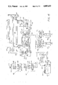
- FIG. 15 is a schematic layout of the hydraulic system of the preferred embodiment of the present invention.
- FIG. 16 is a schematic layout of the electrical system of the preferred embodiment of the present invention.
- FIG. 17 is a fragmentary view, to an enlarged scale, of one type of nozzle that may be used in the practice of the present invention.
- FIG. 18 is a fragmentary view, to an enlarged scale, of another type of nozzle that may be used in the practice of the present invention.
- FIG. 19 is a fragmentary view to an enlarged scale of yet a third type of nozzle that may be used in the practice of the present invention.
- FIG. 20 is a fragmentary perspective view to an enlarged scale of the control panel shown schematically in FIGS. 11-13 showing a preferred manner in which the electrical system of FIG. 16 may be operated.
- FIG. 1 there is shown a mobile base of any suitable construction designated generally by the numeral 10 such as a conventional truck chasis 100 (e.g., the nine wheel chasis of a tractor-trailer combination) appropriately mounted on traction means such as tractor treads, skids or, more preferably, wheels 102 for movement and carrying a suitable power source such as an internal combustion engine (e.g., diesel engine 104) of any conventional construction.
- Stabilizing means such as a pair of hydraulically powered stabilizing jacks 106--106 are mounted to the chasis 100 at the rear end thereof to stabilize the truck chasis 100 against movement when the tube bundle cleaner 10 of the present invention is at a desired location.
- Water pressuring means such as a variable speed, high volume, high pressure, positive displacement pump 200 is mounted on the chasis 100.
- Power transmission means of any suitable construction are provided for powering the water pressuring means.
- the transmission of the truck (not shown) is operatively connected with a gear splitter box 216 which powers a pump drive shaft 202 which, in turn, is operatively connected with a drive chain 204.
- the drive chain 204 is connected with the drive shaft (not shown) for the pump 200.
- Water supply means interconnected with the water pressuring means are provided for the delivery of water thereto.
- the water supply means may be of a conventional construction but, in accordance with the preferred embodiment of the present invention shown in the drawings, will be interconnected with the pressured water delivery means (to be described) in order to permit periodic recycle while the water pressuring means is in operation.
- a water tank 206 open to the atmosphere is mounted on the chasis 100, preferably adjacent the cab of the truck.
- Water channeled through a pipe (not shown) from an extraneous source is connected to the unit 10 at water inlet junction 210 mounted on the chasis 100 and from thence through a water inlet line 209 to water tank 206.
- a pipe not shown
- water line 208 leads from the water tank 206 to the suction side of the pump 200.
- Water under pressure is delivered from the pump 200 to a pump discharge line 300 containing a normally open main valve 304 which may suitably be a pneumatically powered remotely controlled shut-off valve of any conventional construction.
- a water recycle line 302 containing a normally closed recycle valve 303 branches from the pump discharge line 300 to recycle water to the water tank 206 in a manner and for a purpose to be later described.
- the water pressuring means deliver water at a predetermined pressure and volume to pressured water delivery means of any appropriate construction which will comprise, for example, an assembly of several connected pipes and reinforced flexible high pressure hoses adapted to the specific construction of the articulatable support means (to be described) for pressured flow of water to the water discharge means (to be described).
- the pump discharge line 300 leads to the boom delivery pipe 306 which, in turn, leads through the interior of the pedestal 402 to a swivel valve 307 of any suitable conventional construction leading to the boom pipe 308.
- the support means for the water delivery means should be articulatable for both vertical and horizontal movement and should comprise channels for carrying the tubular members comprising the water delivery means in order to provide support, where necessary, but more importantly, as a safety measure to minimize damage to equipment in the event of a rupture and to minimize the risk of injury to operating personnel.
- Horizontal and vertical articulation are conveniently provided through the provision of a boom horizontally rotatably mounted on the chassis 100 and through the provision of appropriate means, such as rack and pinion gears, hydraulic pistons, etc., carried by the boom in order to provide for vertical movement thereof.
- a pedestal is mounted on the chasis 100 and the boom is mounted on the pedestal.
- a cylindrical boom pedestal 402 is mounted on the chasis 100
- a rotating boom gear 404 is mounted on the boom pedestal 402 in engagement with a power driven pinion gear 406 for rotating the boom 410 in a horizontal direction.
- the pinion gear 406 is powered by a hydraulic motor 407 which is also mounted on the boom 402.
- a boom support 408 is mounted on the boom gear 404.
- a channelled boom 410 is rotatably supported on the boom support 408 by means of a boom trunion 416 which carries a boom cylinder support 414 to which boom height hydraulic cylinder 412 is mounted at the lower end thereof.
- a boom height control piston 417 interconnects with a pivotal boom piston support 418 mounted on the channelled boom 410.
- the support means may consist essentially of a boom, such as the boom 410, the water delivery means may be terminated at the end of the boom 410 and the water discharge means (to be described) may be interconnected with the water delivery means at the end of the boom 410.
- scope means are provided at the end of the boom 410 for carrying an extension of the water delivery means.
- the scope means can be of a known general construction comprising, for example, one or more pieces of pipe of the same or varying length (not shown) that can be bolted or threaded to the end of the boom 410 in a conventional manner.
- the channeled scope means 420 mounted on the top of the channelled boom 410.
- the channeled scope 420 is suitably rectangular in shape and is supported at its forward end by rollers 422 so that actuation of a scope cylinder 424 will cause extension of scope extender piston 426 to thereby extend the scope 420.
- the scope extender piston 426 is interconnected at its forward end to the scope 420 by an adapter bar 428.
- Reinforced, flexible hoses capable of withstanding an internal pressure of about 10,000 psig. or more are flexible (i.e. bendable) only within comparatively narrow limits so that the minimum safe radius of curvature increases exponentially with the thickness and diameter of the hose. Therefore, in order to maintain reasonable dimensions for the channeled boom, a plurality of reinforced high pressure hoses (e.g., four hoses) having an outer diameter of about 4 inches are used to transfer water from the boom hose 308 to the scope 420.
- a boom hose manifold 312 is provided at the end of boom hose 308 similar in construction to a water manifold 430 at the rear end of the channeled scope 420 and the manifolds 312 and 430 are fluidly interconnected with a plurality of reinforced, flexible high pressure hoses 310 (only one of which is shown in the drawings).
- the water manifold 430 receives water under pressure from boom hose 310 and delivers it to a scope conduit 431 housed in the scope 420 and extending therethrough for interconnection with a scope discharge port 433 provided with a flanged end plate 435. This is shown more clearly in FIGS. 3, 3A and 3B.
- the water discharge means to be connected to the outlet of the water delivery means may be of any suitable construction and may comprise a nozzle or a plurality of nozzles of different construction for use in different situations.
- FIGS. 17, 18 and 19 a few of the many types of nozzles that can be used are shown by way of example and illustration.
- an appropriate nozzle assembly may be fitted to the end plate 435, as shown, for exampe, in FIG. 17.
- a flanged nozzle adapter 140 is secured to the face of flanged end plate 435 by any suitable means, such as, for example, by means of nuts 142 secured to bolts 144 passing through aligned bolt holes 146-148 in the flanges of the end plate 435 and the nozzle adapter 140.
- a tubular connector 150 provided at the free end thereof with, for example, the spoked member 152 of a hammer-nut union is fixed to the nozzle adapter 14 (e.g., by external threads 154). It will be observed that the tubular connector 150 is angled (e.g., at an angle of about 100°-115°) from the axis of the scope 420. This is a desirable feature because the scope 420 will normally be at an acute angle from the horizontal when it is extended and positioned for tube bundle cleaning operations. With this construction, the free end of the tubular connector will be in an essentially vertical position while in use.
- a hammer union mate 156 is securely threaded to the spoked member 152 and an exteriorly threaded plug 158 is, in turn, secured to the hammer union mate 156.
- the plug 158 is provided with one or more circular openings into which water jet tips 160 may be secured. For example, if the fouling deposits on the shell side of the tube bundle are comparatively soft and are selectively easy to remove, two or three of the water jet tips 160 may be used, while only one will be used if the fouling deposits are of a more refractory nature.
- the hammer union mate 156 may be removed from the spoked member 152 and, with reference to FIG. 18, an elongate hammer union mate 162 may be fixed thereto.
- the elongate mate 162 is connected with a second spoked hammer union member 164 by any suitable means, such as an elbow joint 166 secured to the elongate mate 164 and the second spoked hammer union member 164 may be exteriorly threaded connections 168 and 170.
- a second hammer union mate 172 can then be secured to the second spoked hammer member 164 and a plug 158 equipped with a water jet tip 170 can be secured to the second hammer union mate 172 so that water can be jetted into the end plate of a tube bundle in a horizontal direction.
- a cleaning lance will comprise an elongate tube, preferably made from high strength steel, having a diameter less than the diameter of a tube to be cleaned and provided with means, such as threads, for interconnection with a water supply source at one end and with a nozzle, such as an onion-shaped ball nozzle at the other end.
- the cap is drilled about the periphery thereof with a plurality of orifices facing forwardly, laterally and rearwardly of the path of travel of the lance so that carbonaceous and/or calcareous deposits loosened by the forwardly-directed orifices are dislodged and swept past the cap for flow from the tube being cleaned.
- a rapid and dangerous build-up of hydrostatic pressure will occur that can rupture the lance and injure the operator.
- a novel and unique multi-lance cleaning system which solves the foregoing and other problems associated with using a plurality of water lances to simultaneously clean a plurality of tubes in a tube bundle.
- the multi-lance tube cleaning system 700 comprises an elongate frame 700 which is channeled so as to define a chamber 701. As is shown more clearly in FIG. 8, the elongate frame assembly 700 is provided with a slot 708 which extends the substantial length of the frame 700. The rear of the elongate frame 740 is closed with a rear end plate 707. It will be noticed that the depth of tbe frame 700 adjacent the rear end thereof is significantly greater than the depth adjacent the front end thus, roughly, dividing the chamber 701 into a stock segment 703 and a barrel segment 705.
- a hydraulic motor 712 is mounted to the frame 700 in the stock segment 703 of the chamber 701 adjacent the front end thereof and a power gear 710 is fixed to the hydraulic motor 710.
- a plurality of idler gears 714 are mounted in the chamber 701 of the elongate frame assembly 700 adjacent the front end thereof and the back end thereof to provide a guide means for an endless chain 716 which is connected at the front end thereof to manifold means 706 and at the rear end thereof to moveable drag chain mount 726.
- the manifold means 706 which may suitably be a rectangular block of stainless steel is movably mounted in a lance housing 702.
- a plurality (e.g., four) of hoses 720 capable of carrying water at a pressure of 10,000 to 15,000 pounds per square inch feed to the manifold means 706 through a plurality of feed pipes 709.
- the hoses 720 are suitably connected to the nipples 188 of a manifold 180 and enter the front end of the stock segment 703 of the elongate frame 740 through forward side opening 711.
- the manifold 180 is, in essence, a tubular pipe 182 having a third hammer union mate 184 fixed to one end thereof and adapted to be secured to the spoked hammer union member 152 which is secured by way of tubular connector 150 and nozzle adapter 140 to the flanged end plate 435 at the end of scope 420 (see FIG. 17).
- the other end of the tubular pipe 182 is fitted to a universal joint 186 which, in turn, is secured to a support flange 722 mounted on lance housing 702.
- Nipples 188 are secured to the tubular pipe 182 along the length thereof; the nipples 188 preferably being of a design such that the hoses 720 can be connected thereto with quick connect-disconnect couplings.
- the hoses 720 are nested in a suitable means such as a drag chain 718 which is fixed to the elongate frame 740 by fixed drag chain mount 728 and pass along the drag chain 718 to feed pipes 709 leading to the manifold means 706.
- the drag chain 718 is mounted to the manifold means 706 by a movable drag chain mount 726 which extends through the slot 708 at the top of the elongate frame assembly 740.
- Drag chains are known articles of commerce used to carry hoses and other conduits that move forwardly and backwardly along a linear path of travel.
- the hoses and lines, being nested in the drag chain, as shown in FIGS. 7, 8 and 9, are thus protected from injury from outside forces and protect equipment and operators outside of the drag chain from injury in the event one of the conduits ruptures.
- An advantage of a drag chain is that the radius of curvature of the links of the chain can be controlled with precision and, therefore, items such as high pressure water hoses that can be safely arched within prescribed radii of curvature can be cradled in the drag chain for safe and effective use.
- the safe radium of curvature of a high pressure water hose is a function of the outer diameter and wall thickness of the hose.
- the smaller the diameter of the hose the smaller the radius of curvature.
- Advantage is taken of this feature in the practice of the present invention.
- a plurality of small-diameter, high pressure water hoses are connected in parallel with the pipe 180 (FIG. 10) and the manifold means 706 (FIG. 7) so that a drag chain having a comparatively small radius of curvature can be used.
- the bulk of the multi-lance tube cleaning system 70 can be reduced significantly from the bulk that would be required if a single high pressure water hose and a larger drag chain having a significantly larger radius of curvature were used. It will be understood, however, that one or two, three, four or more high pressure water hoses connected in parallel can be used, as desired, with essentially equivalent results insofar as effective tube cleaning is concerned.
- the depth of the stock segment 703 is primarily determined by the angle of curvature of the drag chain 718 which, in turn, in accordance with conventional practice, will be set to conform to the design radius of curvature for the water hoses 720.
- a plurality of tube cleaning lances 704 are mounted in the channeled lance housing 702, being fixed at their rear ends to the manifold means 706 and extending outwardly from the elongate frame 740 at their cleaning ends.
- the front end of the elongate frame 740 is preferably closed with a lance guide plate 724 provided with openings through which the lances 704 can pass. Still more preferably, a relatively short guide tube 739 will surround each of the openings in the lance guide plate 724.
- the heads of the cleaning lances 704 and the guide tubes 739 will be spaced from each other in a spacing pattern which is the same as the spacing pattern of the tubes to be cleaned. If the spacing pattern of the tubes to be cleaned differs significantly from the spacing pattern of the tubes 739, the lance guide plate 724 may be replaced with a different lance guide plate (not shown) having a different, needed pattern. If there are only minor differences in alignment between the alignment of the tubes 739 in end plate 724 and the tubes to be cleaned, a rectangular template (not shown) having holes therein with the same spacing pattern as the tubes to be cleaned, may be urged over the outer ends of the tubes 739 to thereby conform their spacing pattern to the spacing pattern of the tubes to be cleaned.
- the manifold 706 in this operation performs a plurality of functions.
- the tapped interior of the manifold 706 acts as a reservoir for water fed thereto through the lines 720 and the feed pipe 709, and as a pressure equalizer so that equal pressure is maintained and the water flowing through each of the lances 704.
- the pressure on that lance will instantly and automatically be adjusted to the hydrostatic pressure in the manifold 706, thus preventing the type of disastrous pressure build-up in cleaning lances that has heretofore plagued the tube bundle cleaning industry.
- Manifold 206 also serves as a rear support for the lances 704, and as a support for the forward end of the drag chain 718 encasing the water hoses 720 and, finally, by virtue of drag chain mount 726, as a guide for the drag chain as the lances are progressively extended into a tube bundle.
- the multi-lance tube cleaning assembly 70 is preferably used as an integral part of the articulatable tube bundle cleaner 10 of the present invention in the interst of economy and simplicity of operations.
- the multi-lance tube cleaning assembly 70 can be operated as a separate unit, being independently supported on a suitable base such as a mobile crane, a wheeled tractor, skids, etc. (not shown), and independently supplied with water from an independent water delivery system comprising a separate pump (not shown) mounted on the same or a different movable base and independently supplied with power from a separate source (not shown) such as an internal combustion engine, in order to deliver a high volume, high pressure stream of water on demand.
- controls similar to those shown in FIG. 15 and FIG. 16 would be independently provided and would not be integrated into a remote control panel 900 such as the panel shown in FIG. 21. It would be possible, however, with such a construction to clean the interior of the tubes of a tube bundle at a location different from the location for cleaning the shell side of the tube bundle or at a different time or from a different extraneous water source.
- articulation of the cleaning nozzles is augmented through the provision of articulatable head aligning means such as, for example, the articulatable head aligning means 800 shown in FIGS. 4, 5 and 6.
- This embodiment of the present invention is particularly useful when a tube bundle is to be cleaned on-site.
- the exterior surfaces of the tubes of a tube bundle may not require cleaning, although there is appreciable fouling of the interior of the tube. In such a situation, there is no need to remove the tube bundle from its shell if it can be cleaned in place.
- This can be accomplished in accordance with the present invention by using the mobile base 10 to maneuver the articulatable tube bundle cleaner to an appropriate location adjacent the tube bundle to be cleaned, attaching the multi-lance tube cleaning system 700 to the flanged end plate 435 as shown in FIG. 10 and FIG. 19 and then adjusting the position of the boom 410 and the scope 420 adjacent the face of the tube bundle to be cleaned and then using the head adjusting means 800 for accurately positioning the multi-lance tube cleaning system 700 in alignment with the tubes of the tube bundle to be cleaned.
- the water delivery means may again terminate with the end plate 435 at the end of scope 420.
- a novel, fully articulatable head means is preferably provided for interconnection with the end plate 435.
- Outlet elbow joint 806 is interiorly threaded, for a purpose to be described.
- Vertical articulation of the articulatable head means 800 is provided by vertical head cylinder 808 appropriately supported on a flanged angle bracket 803 by means of vertical pivot 814.
- a vertical piston rod 812 extends from the piston 808 and interconnects with the elbow joint 806 by means of a pipe clamp 820.
- Horizontal articulation is obtained through the provision of a horizontal cylinder 810 which is mounted to the articulatable head means 800 by a flanged brace 822 fixed to the flanged inlet port 801 by means of a support ring 823.
- a horizontal pivot 818 interconnects with horizontal piston rod 814.
- FIG. 15 there is schematically shown a layout of the hydraulic system that is used in accordance with the present invention showing the interrelationship of the principle components thereof.
- Conventional components such as pressure relief valves, sight gauges, pressure gauges, etc., are not shown since the location, construction and utilization of such components are known to those skilled in the art.
- a reservoir 602 is provided to which hydraulic fluid can be added as needed through fill cap 603. Hydraulic fluid is withdrawn from the tank 602 through a filter 605 and a pump inlet hydraulic line 604 leading to a hydraulic pump 600. Hydraulic fluid is discharged by the hydraulic pump 600 through the hydraulic pump outlet line 606 which is connected in series with a solenoid operated relief valve 608 provided with a relief valve recycle line 610 leading to a tank inlet line 684 by way of which hydraulic fluid can be returned to the tank 602.
- Pump outlet line 606 leads to a pedestal manifold designated generally by the numeral 612 containing a solenoid operated pedestal gear control valve 614 connected in series with a restrictor valve 616 with reverse free flow and a relieving sandwich valve 618.
- a right rotational pedestal gear hydraulic line 617 leads from the relieving sandwich valve 618 to a hydraulic motor 407 utilized to operate boom gear 404 (FIG. 1).
- a pedestal gear left rotation hydraulic 619 also leads to the hydraulic motor 407.
- Hydraulic branch line 622 branching from pump outlet hydraulic line 606 leads in series to a plurality of manifolds.
- a boom manifold designated generally by the numeral 624 containing a boom manifold four-way three-position operating control valve which is fed by hydraulic boom inlet lines 626 and 627. Hydraulic fluid flows through a boom manifold four-way three-position operating control valve 628 and through a boom manifold dual restrictor valve with reverse free flow 629.
- a boom up hydraulic line 630 leads from the valve 629 to the hydraulic boom cylinder 412 (FIG. 1) for raising the boom 410 and a boom down hydraulic line 632 leads to the piston rod side of the piston 412 for lowering the boom 410.
- an articulate head manifold designated generally by the numeral 634 fed by articulate head manifold inlet lines 636, 637, 638 and 639 leading to a pair of multi-lance four-way three-position operating valves 640-642.
- a pair of dual restrictor valves with reverse free flow 644-645 are connected in series with the operating valves 640-642 and articulate head hydraulic lines 646, 647, 648 and 649 lead from dual restrictor valves 644 and 645 to the boom 410, and thence through the boom 410 and scope 420 (FIG. 1) terminating in articulate head quick disconnect outlet line nipples 650, 651, 652 and 653, respectively.
- scope manifold 654 fed by scope manifold hydraulic inlet lines 655 and 657 leading to a scope four-way three-position operating valve 656.
- the valve 656 is connected in series with a scope dual restrictor valve with reverse free flow 658, and a scope dual reducing valve with dual reducing/relieving sandwich valve 660.
- a scope out hydraulic line 662 leads from the valve 660 through a counterbalancing valve 661 to the scope cylinder 424.
- a scope in hydraulic line 663 leads from the valve 660 through the counterbalancing valve 661 piston side of scope cylinder 424.
- a manifold 664 for hydraulic jacks 106--106 (FIG. 1).
- the manifold 664 will suitably be fed by a hydraulic branch line 666 leading from pump outlet line 606.
- Line 668 leads from line 666 to a first four-way three-position operating valve 672.
- Line 666 also leads to a second four-way three-position operating valve 673.
- a left jack down hydraulic line 674 leads from the operating valve 67 as does a left jack up hydraulic line 676.
- a right jack down hydraulic line 678 leads from the operating valve 673 as does a right jack up hydraulic line 680.
- Hydraulic branch line 684 leads to a multi-lance manifold designated generally by the numeral 685 containing a solenoid operated lance water control valve 686 connected in series with a restrictor valve 687 with reverse free flow and a relieving sandwich valve 688.
- a right rotation lance motor hydraulic line 689 leads from relieving sandwich valve 688 to hydraulic motor 712 utilized to extend and retract the cleaning lances.
- a right rotation lance motor hydraulic line 690 also leads from relieving sandwich valve 688 to motor 712.
- Drain lines 681, 682, 683 and 691 are provided for recycling hydraulic fluid to the tank inlet line 684.
- FIG. 16 there is schematically shown the principle components of an electrical control system that can be utilized in accordance with the preferred embodiment of the present invention. Again, only the principle component have been schematically shown and conventional elements such as solenoids, switches, rectifiers, fuses, etc., the construction, utilization and operation of which are known to those skilled in the art, have been omitted.
- the electrical power system is energized by an appropriate power source such as the battery 500 from the diesel engine 104 (FIG. 1).
- a trunk line 502 leads from the positive pole of the power source 500 and a trunk line 504 leads from the negative pole of the power source 500.
- a first four-way toggle switch 510 is connected to the trunk line 502 by toggle switch lead line 512 and from lead lies 514, 516, 518 and 520 to the trunk line 504 in order to complete the circuit.
- the neutral position 529 of the four-way toggle switch 510 may suitably be connected by way of connector 520 with a hydraulic unload lead line 570.
- the lead lines 514-516 may be operatively connected with the hydraulic motor 712 for the multi-lance assembly (FIG. 7).
- Lead line 514 may suitably be connected with the hydraulic motor 712 to retract the lances 704 (FIG. 7) and the lead line 516 may suitably be connected to reverse the direction of rotation of the hydraulic motor 712 in order to extend the lances 704.
- the lead lines 518-520 may be connected with the hydraulic motor 620 (FIG. 15) used to drive the pinion gear 406 for rotation of the rotary boom gear 404 (FIG. 1).
- Feed line 518 may suitably be interconnected with the hydraulic motor 620 so as to actuate the motor to rotate the rotary boom gear 404 to the left while lead line 520 may be interconnected with the motor 620 to actuate the motor 620 to turn the rotary boom gear 404 to the right.
- a second four-way toggle switch 530 energized on the switch side by a lead line 531 may also be provided. Again, in the neutral position the toggle switch will interconnect with a hydraulic unload lead line 539 leading to the hydraulic unload line 570.
- Electrical leads 532 and 534 may be interconnected with the four-way, three position operating control valve 628 (FIG. 15) for raising and lowering the boom 410 by means of hydraulic cylinder 412 (FIG. 1 and FIG. 15).
- Lead lines 536 and 538 may be operatively interconnected with the four-way, three-position operating valve 640 to control right and left movement of the articulating head means 801 by means of cylinder 810 (FIG. 5).
- a third four-way toggle switch 540 energized at the switch side by a lead line 541 may be provided. Again, in the neutral position the toggle switch 549 will interconnect with a hydraulic unload lead line 549 connecting with hydraulic unload line 570.
- the leads 542 and 544 may be interconnected with the control valve 656 (FIG. 15) in order to extend and retract the scope by means of scope cylinder 424 (FIG. 15).
- Lead lines 546 and 548 may be interconnected with operating valve 642 (FIG. 15) in order to regulate upward and downward movement of the articulating head means 800 (FIG. 4).
- a branch line 550 containing a cut-off switch 552 may be interconnected with the solenoid operated unloading relief valve 608 in order to interrupt the flow of water through the water lines 720 (FIG. 7) of the multi-lance unit 700.
- a lead line 557 may interconnect the trunk line 502 with a first two-way switch 556 for controlling vertical movement of the left jack 106 (FIG. 1) mounted on the chasis 100.
- the leads 558 and 559 will be interconnected with the operating valve 672 (FIG. 15).
- a second two-way switch 560 connected with trunk line 502 by a lead line 561 may be provided for regulating up and down movement of the right jack 106.
- the leads 562 and 563 are interconnected with the operating valve 673 (FIG. 15).
- Bridge line 566 interconnects the leads 559 and 562 while a bridge line 568 interconnects the lead lines 558 and 563 in order to balance the system.
- the two bridge lines lead to the hyrdaulic unload line 570 for releasing hydraulic fluid when the two-way valves 556 and 560 are in a neutral position.
- FIG. 20 there is schematically shown in perspective view of the remote control unit that is preferably used in accordance with the present invention.
- the remote control unit designated generally by the numeral 900 may suitably comprise the emergency stop switch 508, the four-way toggle switches 510, 530 and 540 and the water nozzle switch appropriately mounted in a suitable housing 902.
- the switches 508, 510, 530, 540 and 552 may appropriately extend through openings in the housing 902. Trunk lines 502 and 504 will lead from the control unit 900 to the tube cleaning unit mounted on the chasis 100.
- the mobile base 10 of the mobile articulatable tube bundle cleaner 10 of the present invention may be driven to a suitable location adjacent one or more tube bundles such as tube bundles A and B.
- the switches 556 and 560 (FIG. 16) may be interconnected with leads 559 and 563 in order to lower the hydraulic jacks 106 to ground level so as to take at least a portion of the load of the mobile unit 10 so that the chasis 100 will be fixed in an appropriate position.
- tube bundles A and B may previously have been removed from their location within the shells of a heat exchangers and transported to the cleaning station so that the tube bundle cleaning operation can be conducted without interfering with other operations of the manufacturing unit in which the heat exchangers are normally located.
- a water line from a suitable source (not shown) will then be conducted to the water inlet junction 210 in order to provide water for the cleaning operation.
- the diesel engine 104 will be operated at a desired predetermined speed and the power from the diesel will be transmitted via gear splitter box 216 to the drive chain 204 to power the variable speed, high volume, high pressure, positive displacement pump 200.
- water delivered to the water inlet junction 210 will be drawn from thence via water line 209 to water tank 206 and from thence through water inlet line 208 leading to the pump 200.
- valve 303 will continue to open until the volume of water recycled to tank 206 by line 302 is adequate to maintain a constant head of pressure on water leaving pump 200.
- toggle switch 530 (FIG. 21 and FIG. 16) in order to elevate the boom 410 to a desired height.
- Actuation of the switch 430 will interconnect the switch with lead 532 leading to boom manifold 624 in order to actuate valve 628 and 629 to initiate flow of hydraulic fluid through hydraulic fluid line 630 leading to boom height hydraulic cylinder 412. This will result in extension of the piston 417 which, pivoting about cylinder support 414 and piston support 418, will cause the boom 410 to be elevated.
- the toggle switch 530 is returned to the neutral position.
- toggle switch 510 so as to interconnect it with electrical lead 518 leading to pedestal manifold 612 in order to activate valves 616 and 618 so as to cause hydraulic fluid to flow through the hydraulic fluid line 619 to hydraulic motor 407 in order to activate pinion gear 406 so as to rotate boom gear 404 to the left to thereby move the boom 410 leftward until it is in alignment with the tube B to be cleaned.
- the operator would return the toggle switch 510 to its neutral position.
- an appropriate nozzle assembly such as the nozzle assembly shown in FIG. 17 will have been threaded onto flanged end plate 435 of scope conduit 431 to provide an orifice defined by water jet tips 160 through which water may be jetted.
- the operator O would next open switch 552 to initiate flow of a high volume of water under a high pressure such as the pressure of 10,000 pounds per square inch or more through boom delivery pipe 306 to boom hose 308 and thence through scope hose 310 (FIG. 1) to the conduit 431 for the scope 420 (FIG. 3A) at the rate of about 100 gallons per minute or more.
- the operator would then activate toggle switch 540 in order to interconnect it with electrical lead line 542 (FIG. 16) leading to scope manifold 654 in order to actuate valves 656 and 661 so as to initiate a flow of hydralic fluid through the hydraulic fluid flow line 662 leading to the scope cylinder 424.
- the operator can activate the toggle switch 540 so as to interconnect the switch with electrical lead line 544 which, on activation of valves 656 and 661 will cause hydraulic fluid to flow through hydraulic fluid flow line 663 to the piston rod side of the scope cylinder 424 to thereby cause retraction of the piston rod 426 so that the segment of tube bundle B will be subjected to a repeat action on the part of the high pressure, high volume stream of water impacting thereon.
- This operation can be continued for as many times as is necessary to completely clean the segment of the tube bundle B directly under the path of travel of the scope 420.
- the tube bundle B can be rotated about rollers R, R' (FIG. 11) in order to expose another segment of the surface of the tube bundle to the hydroblasting action of the high volume jet of water emerging under high pressure from orifice 160.
- This sequence of operations can be continued segment by segment until the entire periphery of the tube bundle B and, hence, the entire outer surfaces of the tube bundle B have been hydroblasted to a clean condition.
- cleaning operations for tube bundles B can be at least temporarily terminated by activating the switch 552 to again close valve 304 so as to cause water emerging from the pump 200 through line 300 to be recycled back to the tank 206 through line 302.
- the operator O may next unscrew the tubular connector 150 and replace it with hammer union mate 162 (FIG. 18).
- toggle switch 540 is again activated so as to hydroblast the face of the tube bundle B with a jet of high velocity, high pressure water, as described above, so as to remove carbonaceous and/or calcareous deposits form the face of the tube bundle B.
- the hammer union mate 162 (FIG. 18) is removed from the spoked hammer member 152 (FIG. 17) and the third hammer union mate 184 (FIGS. 10 and 19) is threaded into the spoked hammer member 152 and the universal joint 186 is attached to the support flange 722 so that the elongate frame 740 of the multi-lance cleaning system can be articulatably suspended from scope 420.
- the operator O will position the remote control unit 900 at an appropriate safe position which is remote from a tube bundle C, the interiors of the tubes of which are to be cleaned.
- the operator will close switch 552 which is operatively connected to valves 303 and 304 in order to close main cutoff valve 304 and open recycle valve 303 so that water discharged by pump 200 will recycle to tank 206 by way of water recycle line 302.
- the operator will then horizontally rotate boom 410 by moving the toggle of toggle switch 510 to connect with lead line 518 which is operatively connected with hydraulic motion 407 to turn rotating boom gear 404 and, hence, boom 410 to the left, if he so desires or by connecting toggle switch 510 with lead line 520 if he wants to turn boom 410 to the right.
- the operator will adjust the verticle height above the ground of the elongate frame 40 of the multi-lance tube cleaning system 700 by moving toggle switch 530 so as to connect with lead line 532 or lead line 534, which are operatively connected with boom height hydraulic cylinder 412 in order to raise or lower the boom 410.
- the spacing of the tube cleaning lances 704 of the multi-lance tube cleaning system 700 from the face of tube bundle C can be adjusted by moving the toggle of toggle switch 510 to contact lead line 514 or 516 in order to move the scope 420 in or out of the boom 410, as desired.
- the multi-lance tube cleaning system 700 can be brought into parallel alignment with the longitudinal axis of the tube bundle C with the tips of the cleaning lances 704 adjacent the face of the tube bundle C and in close proximity to a plurality of tubes that are to be interiorily cleaned.
- a second operator can safely approach tube bundle C to check the alignment of the cleaning lances 704 and, by movement of the elongate frame 740 about universal joint 186 make sure that the tips of the lances 704 are in, or will enter the plurality of tubes of tube bundle C that are to be cleaned.
- the second operator will then move to a safe position and the operator O will open cutoff switch 552 so that a high volume of high pressure water will be delivered to the cleaning lances 704 from pump 200 by way of pump discharge bit 300, boom delivery pipe 306, boom hose 308, scope hoses 310, scope conduit 421 and manifold 180 and then by way of hoses 720 to pressure equalizing means 706 to which the cleaning lances 704 are connected.
- the operator O will also move the toggle of toggle switch 510 into contact with lead 516 in order to energize hydraulic motor 712 to rotate power gear 710 so that the link chain 716 will move the manifold means 706 which, in turn, will pull drag chain 718 to which it is connected by drag chain mount 726 along slot 708 (FIG. 8) as the lances 704 move into the tubes of tube bundle C with which they are aligned.
- the water jetting from the tips of the lances 704 will clean the inside of the tubes of fouling deposits as the cleaning lances are moved therethrough.
- the "blocked" cleaning lance will not be overpressured because the manifold means 706 will automatically adjust water flow through the other lances to compensate for the blockage. Also, the operator can move the toggle switch 510 back and forth to alternately connect with leads 514 and 516 to move the lances 704 backwards and forwards in the tubes so as to "hammer away" at the plug until it is dislodged. Again, pressure equalization by the manifold means 706 will prevent overpressuring of either the lance or the tube.
- the toggle switch 510 is connected with lead 514 to move the lances 704 out of the cleaned tubes, the water cutoff switch 552 is closed so that water no longer flows to the lances 704, and the lances 704 can then be repositioned in the described manner in order to clean a next selected plurality of tubes. The operation continues in this manner until all of the tubes of tube bundle C have been cleaned.
- FIG. 12 another mode of cleaning the exterior surfaces of a tube bundle D is shown wherein the tube bundle D is transversely mounted on rollers R and R' transversely of the axis of truck chasis 100.
- the cleaning of each segment of the exterior of the tube bundle D is accomplished using the pipe 160 (FIG. 18) at the end of the scope 420.
- the boom 410 is rotated back and forth by activation of the boom gear 404 and extension and/or retraction of the scope 420, as needed.
- the boom 410 can be further rotated and, by use of the articulatable head aligning means 800, used to clean both of the end faces of the tube bundle D without a need for moving either the tube bundle D or the truck chassis 100.
- FIG. 12 the mode of operation of FIG. 12 is thus very advantageous when the total length of the tube bundle D is such that articulation of the boom 410 to the right, to the left and up and down can permit all of the exterior and interior surfaces to be cleaned while the tube bundle D is in one location.
- the tube bundles such as tube bundles A and B are of a length such that the boom and scope cannot be articulated to an arc wide enough to permit cleaning of both faces, then the arrangement of FIG. 11 is preferred.
- FIG. 14 there is a schematic illustration of the advantageous use of the pressure control valve 304 during a cleaning operation.
- frequent interruption of water flow through the boom 420 and the lance system 70 is necessary.
- it is not necessary to interrupt the operation of the pump 200 because the operator, on activation of the switch 552 will close the main cutoff valve 304 and open the recycle valve 303 so that water recycles back to the pump 200 through water recycle line 302 to tank 206 while the pump is operating at its desired predetermined load level.
- the tube bundle cleaner of the present invention comprises a mobile base, water pressuring means, articulatable water delivery means, channeled articulatable support means, water discharge means, and remotely actuatable control means interconnected with the articulatable support means, water pressuring means, and the water delivery means.
- the mobile base may comprise a conventional truck chasis 100 of any suitable construction, such as the nine wheel chasis of a tractor-trailer combination appropriately mounted on wheels 102 for movement, and powered by a diesel engine 104 of any conventional construction.
- a pair of hydraulically powered stabilizing jacks 106 mounted to the chasis 100 at the rear thereof for downward extension are provided to stabilize the mobile base against movement when the unit 10 is in a desired location.
- the water pressuring means may suitably comprise for example, a variable speed, high volume, high pressure, positive displacement pump 200.
- a gear splitter box 216 provides appropriate means for powering a pump drive chain 204 connected with the pump drive shaft 202 for driving the pump 200.
- a water tank 206 mounted on the chasis 100, preferably adjacent the cab of the truck receives water from a pipe connected to an extraneous water source leading to a water inlet junction 210 mounted on chasis 100 and from thence to water tank 206.
- Water line 208 leads from water tank 206 to the suction side of pump 200.
- the water delivery means of the preferred embodiment of the present invention will appropriately comprise a pump discharge line 300 containing a main cutoff valve 304 which may suitably be a pneumatically powered remotely controlled shut-off valve of any conventional construction.
- the pump discharge line 300 leads to a boom delivery pipe 306 which, in turn, leads to a boom hose 308 which is in turn connected to a scope conduit 310.
- the channeled vertically and horizontally movable support means of the present invention may suitably comprise a boom pedestal 402, a boom rotating gear 404, a power driven pinion gear 406 for rotating the boom 410 in a horizontal direction and a boom support 408 on which a channeled boom 410 is mounted.
- a boom height control cylinder 412 is mounted on a boom cylinder support 414 and the piston 417 of the boom height control cylinder 412 is connected at its outer end with a pivotal boom piston support 418.
- a channeled scope 420 is mounted on top of the boom 410.
- Extension of the scope 426 on rollers 422 is controlled by a scope cylinder 424 mounted on the scope 420 and a scope extender piston 426 extending from the cylinder 424 and mounted to the free end of the scope 420 so that the piston 426 may be extended from the cylinder 424 to thereby extend the scope 420.
- the water discharge means of the present invention may suitably comprise, for example, nozzle adapter 140 which may be fixed to the end plate 435 of the scope discharge port 433.
- a tubular connector 150 fitted to the nozzle adapter 140 interconnects with an appropriate nozzle assembly such as plug 158 fitted with water jet tips 160 (FIG. 17), an elbow joint 166 similarly fitted with a plug 158 into which one or more water jet tips 160 are inserted (FIG. 18) or a manifold 180 (FIG. 19) which can be interconnected with the plurality of tube cleaning lances 704 in the manner described above.
- the control means may comprise, for example, a hydraulic pump 600 connected on the suction side to a hydraulic fluid holding tank 602 by a pump inlet line 604.
- a hydraulic pump outlet line 606 passes from the hydraulic pump 600 through a solenoid operated relief valve 608 to a pedestal manifold 612.
- a relief valve recycle line 610 returns to the tank 602 for discharging fluid thereto in the event of an emergency cut off of hydraulic fluid flow by the relief valve 608.
- the control means also includes scope manifold 654 which is suitably provided with branch lines 662 and 663 for extending and retracting the scope, a hydraulic jack manifold 664 from which branch hydraulic lines 674, 676, 678 and 680 lead for raising and lowering the hydraulic jacks 106--106; a boom manifold 624 from which branch hydraulic fluid lines 630 and 632 lead for raising and lowering boom 410; and a manifold 634 from which branch hydraulic fluid lines 650, 651, 652 and 653 lead for operating the articulatable head aligning means 800.
- scope manifold 654 which is suitably provided with branch lines 662 and 663 for extending and retracting the scope, a hydraulic jack manifold 664 from which branch hydraulic lines 674, 676, 678 and 680 lead for raising and lowering the hydraulic jacks 106--106; a boom manifold 624 from which branch hydraulic fluid lines 630 and 632 lead for raising and lowering boom 410; and a manifold 634 from
- the equipment of the present invention is much safer to operate since the pressure lines are all enclosed and are not directly contacted by operators during cleaning operations.
- This highly desirable safety feature also makes possible the provision of the delivery of significantly larger volumes of water at significantly higher pressures from the nozzles for cleaning tube bundles.
- Another advantage shown by this example lies not to much in the very significant savings in man-hours required for the cleaning job as in the significant reduction of cleaning time, meaning that the plant from which the tube bundles were taken for cleaning could be returned to operating service in a significantly shorter period of time.
Abstract
Description
Claims (16)
Priority Applications (12)
| Application Number | Priority Date | Filing Date | Title |
|---|---|---|---|
| US06/773,642 US4805653A (en) | 1985-09-09 | 1985-09-09 | Mobile articulatable tube bundle cleaner |
| JP61205231A JPS6261684A (en) | 1985-09-09 | 1986-09-02 | Cleaner for bundle of tube |
| DE198686112295T DE215396T1 (en) | 1985-09-09 | 1986-09-05 | FREE MOVABLE CLEANING DEVICE FOR TUBE BUNDLE. |
| DE3650545T DE3650545T2 (en) | 1985-09-09 | 1986-09-05 | Movable cleaning device for tube bundles |
| SG1996008930A SG44000A1 (en) | 1985-09-09 | 1986-09-05 | Mobile articulate tube bundle cleaner |
| AT90123232T ATE140644T1 (en) | 1985-09-09 | 1986-09-05 | FREELY MOVABLE CLEANING DEVICE FOR PIPE BUNDLES |
| DE199090123232T DE430306T1 (en) | 1985-09-09 | 1986-09-05 | FREE-MOVING CLEANING DEVICE FOR TUBE BUNDLE. |
| EP90123232A EP0430306B1 (en) | 1985-09-09 | 1986-09-05 | Mobile articulatable tube bundle cleaner |
| DE8686112295T DE3688169T2 (en) | 1985-09-09 | 1986-09-05 | FREE MOVABLE CLEANING DEVICE FOR TUBE BUNDLE. |
| AT86112295T ATE87513T1 (en) | 1985-09-09 | 1986-09-05 | FREE MOVEABLE CLEANING DEVICE FOR PIPE BUNDLES. |
| EP86112295A EP0215396B1 (en) | 1985-09-09 | 1986-09-05 | Mobile articulatable tube bundle cleaner |
| US07/268,338 US4856545A (en) | 1985-09-09 | 1988-11-07 | Multi-lange tube bundle cleaner |
Applications Claiming Priority (1)
| Application Number | Priority Date | Filing Date | Title |
|---|---|---|---|
| US06/773,642 US4805653A (en) | 1985-09-09 | 1985-09-09 | Mobile articulatable tube bundle cleaner |
Related Child Applications (1)
| Application Number | Title | Priority Date | Filing Date |
|---|---|---|---|
| US07/268,338 Division US4856545A (en) | 1985-09-09 | 1988-11-07 | Multi-lange tube bundle cleaner |
Publications (1)
| Publication Number | Publication Date |
|---|---|
| US4805653A true US4805653A (en) | 1989-02-21 |
Family
ID=25098875
Family Applications (2)
| Application Number | Title | Priority Date | Filing Date |
|---|---|---|---|
| US06/773,642 Expired - Lifetime US4805653A (en) | 1985-09-09 | 1985-09-09 | Mobile articulatable tube bundle cleaner |
| US07/268,338 Expired - Lifetime US4856545A (en) | 1985-09-09 | 1988-11-07 | Multi-lange tube bundle cleaner |
Family Applications After (1)
| Application Number | Title | Priority Date | Filing Date |
|---|---|---|---|
| US07/268,338 Expired - Lifetime US4856545A (en) | 1985-09-09 | 1988-11-07 | Multi-lange tube bundle cleaner |
Country Status (6)
| Country | Link |
|---|---|
| US (2) | US4805653A (en) |
| EP (2) | EP0430306B1 (en) |
| JP (1) | JPS6261684A (en) |
| AT (2) | ATE87513T1 (en) |
| DE (4) | DE430306T1 (en) |
| SG (1) | SG44000A1 (en) |
Cited By (33)
| Publication number | Priority date | Publication date | Assignee | Title |
|---|---|---|---|---|
| US4922571A (en) * | 1988-11-14 | 1990-05-08 | Aquatech, Inc. | Vacuum loading machine |
| US5002120A (en) * | 1990-03-08 | 1991-03-26 | Boisture Thomas B | Multi-lance tube cleaning system |
| US5018544A (en) * | 1990-03-06 | 1991-05-28 | Ohmstede Mechanical Services, Inc. | Apparatus for cleaning heat exchanger tube bundles |
| US5022463A (en) * | 1990-03-08 | 1991-06-11 | Ohmstede Mechanical Services, Inc. | Multi-hose flexible lance tube cleaning system |
| US5067558A (en) * | 1990-03-08 | 1991-11-26 | Ohmstede Mechanical Services, Inc. | Multi-lance tube cleaning system |
| US5129455A (en) * | 1990-03-08 | 1992-07-14 | Ohmstede Mechanical Services, Inc. | Multi-lance tube cleaning system having flexible portions |
| US5261600A (en) * | 1992-11-30 | 1993-11-16 | Serv-Tech, Inc. | Vertical tube bundle cleaner |
| US5323529A (en) * | 1992-12-10 | 1994-06-28 | American Mechanical Services, Inc. | Heat exchanger bundle extractor assembly and method |
| US5352297A (en) * | 1993-07-08 | 1994-10-04 | Peters David E | Railroad car spraying method and apparatus |
| US5451002A (en) * | 1993-08-02 | 1995-09-19 | American Mechanical Services, Inc. | Multi-lance for cleaning tube bundles |
| US5564179A (en) * | 1994-02-07 | 1996-10-15 | American Mechanical Services, Inc. | Heat exchanger bundle extractor assembly |
| US6224353B1 (en) * | 1999-05-27 | 2001-05-01 | Zan Iseman | Pump control apparatus and method |
| US6418948B1 (en) * | 1998-10-30 | 2002-07-16 | Thomas G. Harmon | Apparatus and method for removing concrete from interior surfaces of a concrete mixing drum |
| US20040057336A1 (en) * | 2002-09-06 | 2004-03-25 | Smith Richard Lee | Mobile decontamination unit |
| US20070079852A1 (en) * | 2005-09-30 | 2007-04-12 | Blasters, Inc. | Removal of Residual Concrete from Ready Mixed Concrete Drums |
| US20080304922A1 (en) * | 2007-06-10 | 2008-12-11 | James Moon | Extendable fluid transport apparatus |
| US20090014563A1 (en) * | 2007-06-08 | 2009-01-15 | Enzo Giletta | Spreader unit with a supporting arm for deicer spreader assemblies |
| US20110198369A1 (en) * | 2005-02-23 | 2011-08-18 | Air Liquide Industrial U.S. Lp | Concrete cooling injection unit and method of injecting a coolant into a concrete mixture |
| US8246751B2 (en) | 2010-10-01 | 2012-08-21 | General Electric Company | Pulsed detonation cleaning systems and methods |
| US20130220389A1 (en) * | 2012-02-27 | 2013-08-29 | Daniel Wayne Snow | Pipe cleaning apparatus |
| US20150027499A1 (en) * | 2013-07-24 | 2015-01-29 | Babcock & Wilcox Nuclear Energy, Inc. | Multi-angle sludge lance |
| US20150068563A1 (en) * | 2013-09-06 | 2015-03-12 | Nlb Corp. | Automated cleaning system |
| US20170095846A1 (en) * | 2014-07-14 | 2017-04-06 | Mac & Mac Hydrodemolition Inc. | Method and apparatus for high pressure water treatment of the inside of a pipe section |
| US9863727B1 (en) * | 2016-07-11 | 2018-01-09 | David C. Van Fleet | Mobile hydro-blasting equipment and tube lancing containment system |
| US20190112172A1 (en) * | 2017-10-18 | 2019-04-18 | Quanta Associates, L.P. | Systems and methods for drying and cleaning an aerial lift electrically insulated boom |
| US10809023B2 (en) * | 2017-03-20 | 2020-10-20 | Stoneage, Inc. | Flexible tube cleaning lance positioner apparatus |
| US11084067B2 (en) * | 2016-12-12 | 2021-08-10 | Kaercher Futuretech Gmbh | Mobile decontamination system |
| US11090700B1 (en) * | 2020-08-13 | 2021-08-17 | Core Insight Systems, Inc. | System for spraying the interior of a container |
| US20220008965A1 (en) * | 2020-07-07 | 2022-01-13 | James A. McLeod | Clearing Device for Removal of Snow or Ice from a Pipe |
| US20220040741A1 (en) * | 2020-08-06 | 2022-02-10 | Global Barrier Services, Inc. | Systems and methods for surface cleaning and coating |
| US11253883B1 (en) * | 2021-06-09 | 2022-02-22 | Russell R. Gohl | Cavity cleaning and coating system |
| US11535321B1 (en) * | 2022-08-24 | 2022-12-27 | Russell R. Gohl | Trailer system |
| US11958728B2 (en) * | 2017-11-23 | 2024-04-16 | Quanta Associates, L.P. | Systems and methods for drying and cleaning an aerial lift electrically insulated boom |
Families Citing this family (14)
| Publication number | Priority date | Publication date | Assignee | Title |
|---|---|---|---|---|
| FR2646274B1 (en) * | 1989-04-19 | 1991-06-14 | Commissariat Energie Atomique | PROJECTION MACHINE FOR SURFACE TREATMENTS OF THE INTERIOR OF SPEAKERS |
| US5031691A (en) * | 1990-03-08 | 1991-07-16 | Ohmstede Mechanical Services, Inc. | Multi-lance tube cleaning system having sliding plate |
| US5203072A (en) * | 1991-01-17 | 1993-04-20 | Ohmstede Mechanical Services, Inc. | Detachable crane- or boom-operated heat exchanger tube bundle extractor |
| US5169281A (en) * | 1991-01-17 | 1992-12-08 | Ohmstede Mechanical Services, Inc. | Detachable crane- or boom-operated heat exchanger tube bundle extractor |
| NL9101939A (en) * | 1991-11-20 | 1993-06-16 | Meino Jan Van Der Woude | HYDRAULIC ROBOT SPRAY LANCE. |
| DE19510558A1 (en) * | 1995-03-23 | 1996-09-26 | Inro Maschinentechnik Gmbh | Cleaner for heat exchanger elements |
| US5657781A (en) * | 1995-10-10 | 1997-08-19 | Circle S, Inc. | Machine for cleaning rollers in paper producing machines in situ |
| US6685423B1 (en) | 2000-09-25 | 2004-02-03 | Starcon International, Inc. | Method and apparatus for extracting and installing heat exchanger bundles |
| US6729833B2 (en) | 2000-09-25 | 2004-05-04 | Starcon International, Inc. | Method and apparatus for extracting and installing heat exchanger bundles |
| GB0815344D0 (en) * | 2008-08-22 | 2008-10-01 | Chem Europ Bv Ag | Agriculture application machine |
| US8398785B2 (en) * | 2009-08-10 | 2013-03-19 | Nlb Corp. | Rigid lance cleaning system and method therefor |
| US8871033B2 (en) | 2011-04-01 | 2014-10-28 | Stoneage, Inc. | Apparatus for insertion in a tank and method thereof |
| US9328979B2 (en) | 2013-07-30 | 2016-05-03 | Veolia Es Industrial Services, Inc. | Heat exchanger cleaning tool with three axis control |
| CN115790254B (en) * | 2022-12-01 | 2023-09-05 | 扬州永锋工业设备安装有限公司 | MVR evaporator plate replacement online cleaning device |
Citations (13)
| Publication number | Priority date | Publication date | Assignee | Title |
|---|---|---|---|---|
| US1694371A (en) * | 1926-06-05 | 1928-12-11 | Guggenheim Brothers | Multiple-tube cleaner |
| US3074649A (en) * | 1961-03-23 | 1963-01-22 | Duane E Atkinson | Spraying apparatus |
| US3153510A (en) * | 1960-03-04 | 1964-10-20 | Skanska Cementgjuteriet Ab | Rock-tunneling apparatus |
| US3163880A (en) * | 1963-06-17 | 1965-01-05 | Young Spring & Wire Corp | Mobile liquid spray unit |
| US3675721A (en) * | 1970-10-26 | 1972-07-11 | Snorkel Fire Equipment Co | Fire fighting apparatus with telescoping boom |
| US3903912A (en) * | 1970-09-17 | 1975-09-09 | Hydro Vel Services Inc | Tube cleaning system |
| US3938535A (en) * | 1972-08-07 | 1976-02-17 | Browning-Ferris Industries, Inc. | Tube cleaning device |
| JPS5236865A (en) * | 1975-09-17 | 1977-03-22 | Sanko Seisakusho:Kk | High pressure jet washing device |
| US4095305A (en) * | 1975-10-31 | 1978-06-20 | C. H. Heist Corporation | Cleaning apparatus for tubes and tube bundles |
| US4170264A (en) * | 1977-07-27 | 1979-10-09 | Gibson Motor And Machine Service, Inc. | Pump and roll, vehicle with an elevatable water tower |
| US4201342A (en) * | 1978-06-26 | 1980-05-06 | Weldon Hydraulics, Inc. | Mobile refractory apparatus for repairing interior furnace walls |
| US4220170A (en) * | 1979-07-30 | 1980-09-02 | Hebert Chris J | Apparatus for cleaning large tank interiors |
| US4252274A (en) * | 1979-11-01 | 1981-02-24 | Kubacak Johnny L | Roadside spray apparatus |
Family Cites Families (1)
| Publication number | Priority date | Publication date | Assignee | Title |
|---|---|---|---|---|
| NL9102076A (en) * | 1991-12-12 | 1993-07-01 | Arc Holland B V | PENDANT FOR SAUSAGES E.D. |
-
1985
- 1985-09-09 US US06/773,642 patent/US4805653A/en not_active Expired - Lifetime
-
1986
- 1986-09-02 JP JP61205231A patent/JPS6261684A/en active Pending
- 1986-09-05 DE DE199090123232T patent/DE430306T1/en active Pending
- 1986-09-05 DE DE8686112295T patent/DE3688169T2/en not_active Expired - Fee Related
- 1986-09-05 DE DE198686112295T patent/DE215396T1/en active Pending
- 1986-09-05 AT AT86112295T patent/ATE87513T1/en not_active IP Right Cessation
- 1986-09-05 AT AT90123232T patent/ATE140644T1/en not_active IP Right Cessation
- 1986-09-05 EP EP90123232A patent/EP0430306B1/en not_active Expired - Lifetime
- 1986-09-05 EP EP86112295A patent/EP0215396B1/en not_active Expired - Lifetime
- 1986-09-05 SG SG1996008930A patent/SG44000A1/en unknown
- 1986-09-05 DE DE3650545T patent/DE3650545T2/en not_active Expired - Fee Related
-
1988
- 1988-11-07 US US07/268,338 patent/US4856545A/en not_active Expired - Lifetime
Patent Citations (13)
| Publication number | Priority date | Publication date | Assignee | Title |
|---|---|---|---|---|
| US1694371A (en) * | 1926-06-05 | 1928-12-11 | Guggenheim Brothers | Multiple-tube cleaner |
| US3153510A (en) * | 1960-03-04 | 1964-10-20 | Skanska Cementgjuteriet Ab | Rock-tunneling apparatus |
| US3074649A (en) * | 1961-03-23 | 1963-01-22 | Duane E Atkinson | Spraying apparatus |
| US3163880A (en) * | 1963-06-17 | 1965-01-05 | Young Spring & Wire Corp | Mobile liquid spray unit |
| US3903912A (en) * | 1970-09-17 | 1975-09-09 | Hydro Vel Services Inc | Tube cleaning system |
| US3675721A (en) * | 1970-10-26 | 1972-07-11 | Snorkel Fire Equipment Co | Fire fighting apparatus with telescoping boom |
| US3938535A (en) * | 1972-08-07 | 1976-02-17 | Browning-Ferris Industries, Inc. | Tube cleaning device |
| JPS5236865A (en) * | 1975-09-17 | 1977-03-22 | Sanko Seisakusho:Kk | High pressure jet washing device |
| US4095305A (en) * | 1975-10-31 | 1978-06-20 | C. H. Heist Corporation | Cleaning apparatus for tubes and tube bundles |
| US4170264A (en) * | 1977-07-27 | 1979-10-09 | Gibson Motor And Machine Service, Inc. | Pump and roll, vehicle with an elevatable water tower |
| US4201342A (en) * | 1978-06-26 | 1980-05-06 | Weldon Hydraulics, Inc. | Mobile refractory apparatus for repairing interior furnace walls |
| US4220170A (en) * | 1979-07-30 | 1980-09-02 | Hebert Chris J | Apparatus for cleaning large tank interiors |
| US4252274A (en) * | 1979-11-01 | 1981-02-24 | Kubacak Johnny L | Roadside spray apparatus |
Cited By (52)
| Publication number | Priority date | Publication date | Assignee | Title |
|---|---|---|---|---|
| US4922571A (en) * | 1988-11-14 | 1990-05-08 | Aquatech, Inc. | Vacuum loading machine |
| US5018544A (en) * | 1990-03-06 | 1991-05-28 | Ohmstede Mechanical Services, Inc. | Apparatus for cleaning heat exchanger tube bundles |
| US5002120A (en) * | 1990-03-08 | 1991-03-26 | Boisture Thomas B | Multi-lance tube cleaning system |
| US5022463A (en) * | 1990-03-08 | 1991-06-11 | Ohmstede Mechanical Services, Inc. | Multi-hose flexible lance tube cleaning system |
| US5067558A (en) * | 1990-03-08 | 1991-11-26 | Ohmstede Mechanical Services, Inc. | Multi-lance tube cleaning system |
| US5129455A (en) * | 1990-03-08 | 1992-07-14 | Ohmstede Mechanical Services, Inc. | Multi-lance tube cleaning system having flexible portions |
| US5261600A (en) * | 1992-11-30 | 1993-11-16 | Serv-Tech, Inc. | Vertical tube bundle cleaner |
| US5323529A (en) * | 1992-12-10 | 1994-06-28 | American Mechanical Services, Inc. | Heat exchanger bundle extractor assembly and method |
| US5383271A (en) * | 1992-12-10 | 1995-01-24 | Amuny; Jim E. | Heat exchanger bundle extractor assembly and method |
| US5352297A (en) * | 1993-07-08 | 1994-10-04 | Peters David E | Railroad car spraying method and apparatus |
| US5735964A (en) * | 1993-08-02 | 1998-04-07 | Amuny; Jim E. | Method for cleaning tube bundles |
| US5451002A (en) * | 1993-08-02 | 1995-09-19 | American Mechanical Services, Inc. | Multi-lance for cleaning tube bundles |
| US5564179A (en) * | 1994-02-07 | 1996-10-15 | American Mechanical Services, Inc. | Heat exchanger bundle extractor assembly |
| US6418948B1 (en) * | 1998-10-30 | 2002-07-16 | Thomas G. Harmon | Apparatus and method for removing concrete from interior surfaces of a concrete mixing drum |
| US6640817B2 (en) | 1998-10-30 | 2003-11-04 | Thomas G. Harmon | Method for removing concrete from interior surfaces of a concrete mixing drum |
| US6224353B1 (en) * | 1999-05-27 | 2001-05-01 | Zan Iseman | Pump control apparatus and method |
| US20040057336A1 (en) * | 2002-09-06 | 2004-03-25 | Smith Richard Lee | Mobile decontamination unit |
| US7384183B2 (en) * | 2002-09-06 | 2008-06-10 | Global Ground Support, Llc | Mobile decontamination unit |
| US20110198369A1 (en) * | 2005-02-23 | 2011-08-18 | Air Liquide Industrial U.S. Lp | Concrete cooling injection unit and method of injecting a coolant into a concrete mixture |
| US8235576B2 (en) * | 2005-02-23 | 2012-08-07 | Air Liquide Industrial U.S. Lp | Concrete cooling injection unit and method of injecting a coolant into a concrete mixture |
| US20070079852A1 (en) * | 2005-09-30 | 2007-04-12 | Blasters, Inc. | Removal of Residual Concrete from Ready Mixed Concrete Drums |
| US7546843B2 (en) * | 2005-09-30 | 2009-06-16 | Blasters, Llc | Removal of hardened concrete from ready mixed drum interiors using upwardly directed high pressure water |
| US20090014563A1 (en) * | 2007-06-08 | 2009-01-15 | Enzo Giletta | Spreader unit with a supporting arm for deicer spreader assemblies |
| US8308080B2 (en) * | 2007-06-08 | 2012-11-13 | Giletta S.P.A. | Spreader unit with a supporting arm for deicer spreader assemblies |
| US7673910B2 (en) * | 2007-06-10 | 2010-03-09 | James Moon | Extendable fluid transport apparatus |
| US20080304922A1 (en) * | 2007-06-10 | 2008-12-11 | James Moon | Extendable fluid transport apparatus |
| US8246751B2 (en) | 2010-10-01 | 2012-08-21 | General Electric Company | Pulsed detonation cleaning systems and methods |
| US20130220389A1 (en) * | 2012-02-27 | 2013-08-29 | Daniel Wayne Snow | Pipe cleaning apparatus |
| US9597717B1 (en) | 2012-02-27 | 2017-03-21 | Daniel Wayne Snow | Pipe cleaning apparatus |
| US9770741B1 (en) | 2012-02-27 | 2017-09-26 | Daniel Wayne Snow | Pipe cleaning apparatus |
| US9862010B2 (en) * | 2012-02-27 | 2018-01-09 | Daniel Wayne Snow | Pipe cleaning apparatus |
| US20150027499A1 (en) * | 2013-07-24 | 2015-01-29 | Babcock & Wilcox Nuclear Energy, Inc. | Multi-angle sludge lance |
| US20150068563A1 (en) * | 2013-09-06 | 2015-03-12 | Nlb Corp. | Automated cleaning system |
| US9939215B2 (en) * | 2013-09-06 | 2018-04-10 | Nlb Corp. | Automated cleaning system |
| US20170095846A1 (en) * | 2014-07-14 | 2017-04-06 | Mac & Mac Hydrodemolition Inc. | Method and apparatus for high pressure water treatment of the inside of a pipe section |
| US10478870B2 (en) * | 2014-07-14 | 2019-11-19 | Mac & Mac Hydrodemolition Inc. | Method and apparatus for high pressure water treatment of the inside of a pipe section |
| US9863727B1 (en) * | 2016-07-11 | 2018-01-09 | David C. Van Fleet | Mobile hydro-blasting equipment and tube lancing containment system |
| US20180010867A1 (en) * | 2016-07-11 | 2018-01-11 | David C. Van Fleet | Mobile Hydro-Blasting Equipment and Tube Lancing Containment System |
| US11084067B2 (en) * | 2016-12-12 | 2021-08-10 | Kaercher Futuretech Gmbh | Mobile decontamination system |
| US10809023B2 (en) * | 2017-03-20 | 2020-10-20 | Stoneage, Inc. | Flexible tube cleaning lance positioner apparatus |
| US20190112172A1 (en) * | 2017-10-18 | 2019-04-18 | Quanta Associates, L.P. | Systems and methods for drying and cleaning an aerial lift electrically insulated boom |
| US11958728B2 (en) * | 2017-11-23 | 2024-04-16 | Quanta Associates, L.P. | Systems and methods for drying and cleaning an aerial lift electrically insulated boom |
| US20220008965A1 (en) * | 2020-07-07 | 2022-01-13 | James A. McLeod | Clearing Device for Removal of Snow or Ice from a Pipe |
| US11826797B2 (en) * | 2020-07-07 | 2023-11-28 | James A. McLeod | Clearing device for removal of snow or ice from a pipe |
| US20220040741A1 (en) * | 2020-08-06 | 2022-02-10 | Global Barrier Services, Inc. | Systems and methods for surface cleaning and coating |
| US11090700B1 (en) * | 2020-08-13 | 2021-08-17 | Core Insight Systems, Inc. | System for spraying the interior of a container |
| US11253883B1 (en) * | 2021-06-09 | 2022-02-22 | Russell R. Gohl | Cavity cleaning and coating system |
| US20220395851A1 (en) * | 2021-06-09 | 2022-12-15 | Russell R. Gohl | Cavity Cleaning and Coating System |
| US11618049B2 (en) * | 2021-06-09 | 2023-04-04 | Russell R. Gohl | Cavity cleaning and coating system |
| US20230234089A1 (en) * | 2021-06-09 | 2023-07-27 | Russell R. Gohl | Cavity Cleaning and Coating System |
| US11839892B2 (en) * | 2021-06-09 | 2023-12-12 | Russell R. Gohl | Cavity cleaning and coating system |
| US11535321B1 (en) * | 2022-08-24 | 2022-12-27 | Russell R. Gohl | Trailer system |
Also Published As
| Publication number | Publication date |
|---|---|
| DE3688169T2 (en) | 1993-08-26 |
| ATE87513T1 (en) | 1993-04-15 |
| EP0430306A1 (en) | 1991-06-05 |
| DE215396T1 (en) | 1992-08-13 |
| EP0215396B1 (en) | 1993-03-31 |
| DE3688169D1 (en) | 1993-05-06 |
| JPS6261684A (en) | 1987-03-18 |
| DE3650545D1 (en) | 1996-08-29 |
| DE3650545T2 (en) | 1997-01-30 |
| DE430306T1 (en) | 1992-08-13 |
| US4856545A (en) | 1989-08-15 |
| SG44000A1 (en) | 1997-11-14 |
| ATE140644T1 (en) | 1996-08-15 |
| EP0215396A2 (en) | 1987-03-25 |
| EP0215396A3 (en) | 1988-01-20 |
| EP0430306B1 (en) | 1996-07-24 |
Similar Documents
| Publication | Publication Date | Title |
|---|---|---|
| US4805653A (en) | Mobile articulatable tube bundle cleaner | |
| US4817653A (en) | Tank cleaning, water washing robot | |
| US5018544A (en) | Apparatus for cleaning heat exchanger tube bundles | |
| AU621888B2 (en) | Device for positioning and stabbing casing from a remote selectively variable location | |
| EP0343878B1 (en) | Hydrocleaning of the exterior surface of a pipeline to remove coatings | |
| EP1825736B1 (en) | Connection of the hitch arm of a pull-type crop harvesting machine to a tractor | |
| US5408766A (en) | Hydraulic excavating machine | |
| MX2008011437A (en) | System for conducting jointed pipe and coiled tubing operations. | |
| JP6324934B2 (en) | Watering attachment, work machine and watering system | |
| US6273512B1 (en) | Hydrovac excavating blast wand | |
| US7032676B2 (en) | Well string injection system and method | |
| CN103002996A (en) | Method and apparatus for cleaning vessels | |
| WO2006015272A1 (en) | Aerial boom attachment | |
| US4236591A (en) | Off-road vehicle that both oscillates and articulates | |
| US20020015618A1 (en) | Concrete placing machine with hydraulic and concrete swivel | |
| US4616979A (en) | Mobile pump system | |
| AU2009226121A1 (en) | Portable coring machine | |
| US5940920A (en) | Pipe cleaning apparatus | |
| US5735964A (en) | Method for cleaning tube bundles | |
| KR19990068008A (en) | Tank washing apparatus and method | |
| US6009956A (en) | Method and apparatus for distributing fluid to a leach field surface | |
| US7275475B2 (en) | Apparatus driven by a pressurized medium | |
| CN109826574B (en) | Integrated operation system of small repair well machine | |
| CN212469133U (en) | Pipeline cleaning device | |
| US10480265B1 (en) | Combination hydraulic catwalk and power swivel |
Legal Events
| Date | Code | Title | Description |
|---|---|---|---|
| AS | Assignment |
Owner name: MAC TECH, LTD., A LIMITED PARTNERSHIP OF TEXAS Free format text: ASSIGNMENT OF ASSIGNORS INTEREST.;ASSIGNORS:KRAJICEK, RICHARD W.;CRADEUR, ROBERT R.;REEL/FRAME:004456/0657 Effective date: 19850904 |
|
| FEPP | Fee payment procedure |
Free format text: PAYOR NUMBER ASSIGNED (ORIGINAL EVENT CODE: ASPN); ENTITY STATUS OF PATENT OWNER: LARGE ENTITY |
|
| AS | Assignment |
Owner name: SERV-TECH, INC., 5599 SAN FEPIPE, SUITE 1212, HOUS Free format text: ASSIGNMENT OF ASSIGNORS INTEREST.;ASSIGNOR:MAC-TECH, LTD.;REEL/FRAME:004619/0291 Effective date: 19860908 |
|
| STCF | Information on status: patent grant |
Free format text: PATENTED CASE |
|
| FPAY | Fee payment |
Year of fee payment: 4 |
|
| FEPP | Fee payment procedure |
Free format text: PAT HLDR NO LONGER CLAIMS SMALL ENT STAT AS SMALL BUSINESS (ORIGINAL EVENT CODE: LSM2); ENTITY STATUS OF PATENT OWNER: LARGE ENTITY |
|
| FPAY | Fee payment |
Year of fee payment: 8 |
|
| AS | Assignment |
Owner name: TEXAS COMMERCE BANK NATIONAL ASSOCIATION, TEXAS Free format text: SECURITY INTEREST;ASSIGNOR:SERV-TECH, INC.;REEL/FRAME:008334/0627 Effective date: 19961112 |
|
| AS | Assignment |
Owner name: PHILIP ST, INC., TEXAS Free format text: CHANGE OF NAME;ASSIGNOR:SERV-TECH, INC.;REEL/FRAME:009257/0359 Effective date: 19971222 Owner name: CANADIAN IMPERIAL BANK OF COMMERCE, AS SECURITY AG Free format text: SECURITY AGREEMENT;ASSIGNOR:PHILIP ST, INC.;REEL/FRAME:009257/0398 Effective date: 19980316 |
|
| AS | Assignment |
Owner name: SERV-TECH, INC., TEXAS Free format text: RELEASE;ASSIGNOR:CHASE BANK OF TEXAS NATIONAL ASSOCIATION, AS AGENT FORMERLY, TEXAS COMMERCE BANK NATIONAL ASSOCIATION, AS AGENT;REEL/FRAME:010719/0952 Effective date: 20000229 |
|
| AS | Assignment |
Owner name: PHILIP ST, INC., TEXAS Free format text: RELEASE BY SECURED PARTY;ASSIGNOR:CANADIAN IMPERIAL BANK OF COMMERCE, AS SECURITY AGENT;REEL/FRAME:010742/0466 Effective date: 20000331 |
|
| AS | Assignment |
Owner name: FOOTHILL CAPITAL CORPORATION, AS COLLATERAL AGENT, Free format text: SECURITY INTEREST;ASSIGNOR:PHILIP SERVICES CORPORATION;REEL/FRAME:010731/0814 Effective date: 20000331 |
|
| FPAY | Fee payment |
Year of fee payment: 12 |
|
| AS | Assignment |
Owner name: PSC INDUSTRIAL OUTSOURCING, INC., TEXAS Free format text: ASSIGNMENT OF ASSIGNORS INTEREST;ASSIGNOR:PHILIP ST. INC.;REEL/FRAME:015418/0083 Effective date: 20001229 |
|
| AS | Assignment |
Owner name: AMERICAN MECHANICAL SERVICES, INC. (NOW KNOWN AS M Free format text: ASSIGNMENT OF ASSIGNORS INTEREST;ASSIGNOR:FOOTHILL CAPITAL CORPORATION;REEL/FRAME:014615/0623 Effective date: 20030302 Owner name: PHILIP SERVICES CORPORATION, TEXAS Free format text: ASSIGNMENT OF ASSIGNORS INTEREST;ASSIGNOR:FOOTHILL CAPITAL CORPORATION;REEL/FRAME:014615/0623 Effective date: 20030302 Owner name: PSC INDUSTRIAL OUTSOURCING, INC., TEXAS Free format text: ASSIGNMENT OF ASSIGNORS INTEREST;ASSIGNOR:FOOTHILL CAPITAL CORPORATION;REEL/FRAME:014615/0623 Effective date: 20030302 |
|
| AS | Assignment |
Owner name: LULING ACQUISITION, L.L.C., TEXAS Free format text: ASSIGNMENT OF ASSIGNORS INTEREST;ASSIGNOR:PSC INDUSTRIAL OUTSOURCING, INC.;REEL/FRAME:014615/0725 Effective date: 20030214 Owner name: P2S, LLC, TEXAS Free format text: CHANGE OF NAME;ASSIGNOR:LULING ACQUISITION, L.L.C.;REEL/FRAME:015418/0075 Effective date: 20030310 |
|
| AS | Assignment |
Owner name: RECYCLAGE D'ALUMINIUM QUEBEC INC./QUEBEC ALUMINUM Free format text: TERMINATION OF SECURITY INTEREST;ASSIGNORS:WELLS FARGO FOOTHILL, INC. (FORMERLY KNOWN AS FOOTHILL CAPITAL CORPORATION), AS TRANCHE A COLLATERAL AGENT;WELLS FARGO FOOTHILL, INC. (FORMERLY KNOWON AS FOOTHILL CAPITAL CORPORATION), AS TRANCHE B COLLATERAL AGENT;HIGH RIVER LIMITED PARTNERSHIP, AS PIK/TERM COLLATERAL AGENT, A DELAWARE LIMITED PARTNERSHIP;REEL/FRAME:017846/0935 Effective date: 20041230 Owner name: PHILIP SERVICES CORPORATION, TEXAS Free format text: TERMINATION OF SECURITY INTEREST;ASSIGNORS:WELLS FARGO FOOTHILL, INC. (FORMERLY KNOWN AS FOOTHILL CAPITAL CORPORATION), AS TRANCHE A COLLATERAL AGENT;WELLS FARGO FOOTHILL, INC. (FORMERLY KNOWON AS FOOTHILL CAPITAL CORPORATION), AS TRANCHE B COLLATERAL AGENT;HIGH RIVER LIMITED PARTNERSHIP, AS PIK/TERM COLLATERAL AGENT, A DELAWARE LIMITED PARTNERSHIP;REEL/FRAME:017846/0935 Effective date: 20041230 Owner name: RESI ACQUISITION (DELAWARE) CORPORATION, A DELAWAR Free format text: TERMINATION OF SECURITY INTEREST;ASSIGNORS:WELLS FARGO FOOTHILL, INC. (FORMERLY KNOWN AS FOOTHILL CAPITAL CORPORATION), AS TRANCHE A COLLATERAL AGENT;WELLS FARGO FOOTHILL, INC. (FORMERLY KNOWON AS FOOTHILL CAPITAL CORPORATION), AS TRANCHE B COLLATERAL AGENT;HIGH RIVER LIMITED PARTNERSHIP, AS PIK/TERM COLLATERAL AGENT, A DELAWARE LIMITED PARTNERSHIP;REEL/FRAME:017846/0935 Effective date: 20041230 Owner name: 21ST CENTURY ENVIRONMENTAL MANAGEMENT, INC. OF RHO Free format text: TERMINATION OF SECURITY INTEREST;ASSIGNORS:WELLS FARGO FOOTHILL, INC. (FORMERLY KNOWN AS FOOTHILL CAPITAL CORPORATION), AS TRANCHE A COLLATERAL AGENT;WELLS FARGO FOOTHILL, INC. (FORMERLY KNOWON AS FOOTHILL CAPITAL CORPORATION), AS TRANCHE B COLLATERAL AGENT;HIGH RIVER LIMITED PARTNERSHIP, AS PIK/TERM COLLATERAL AGENT, A DELAWARE LIMITED PARTNERSHIP;REEL/FRAME:017846/0935 Effective date: 20041230 Owner name: ADVANCED ENVIRONMENTAL SYSTEMS, INC., A NEW YORK C Free format text: TERMINATION OF SECURITY INTEREST;ASSIGNORS:WELLS FARGO FOOTHILL, INC. (FORMERLY KNOWN AS FOOTHILL CAPITAL CORPORATION), AS TRANCHE A COLLATERAL AGENT;WELLS FARGO FOOTHILL, INC. (FORMERLY KNOWON AS FOOTHILL CAPITAL CORPORATION), AS TRANCHE B COLLATERAL AGENT;HIGH RIVER LIMITED PARTNERSHIP, AS PIK/TERM COLLATERAL AGENT, A DELAWARE LIMITED PARTNERSHIP;REEL/FRAME:017846/0935 Effective date: 20041230 Owner name: ALLWASTE TANK CLEANING, INC., A GEORGIA CORPORATIO Free format text: TERMINATION OF SECURITY INTEREST;ASSIGNORS:WELLS FARGO FOOTHILL, INC. (FORMERLY KNOWN AS FOOTHILL CAPITAL CORPORATION), AS TRANCHE A COLLATERAL AGENT;WELLS FARGO FOOTHILL, INC. (FORMERLY KNOWON AS FOOTHILL CAPITAL CORPORATION), AS TRANCHE B COLLATERAL AGENT;HIGH RIVER LIMITED PARTNERSHIP, AS PIK/TERM COLLATERAL AGENT, A DELAWARE LIMITED PARTNERSHIP;REEL/FRAME:017846/0935 Effective date: 20041230 Owner name: ALLWORTH, INC., AN ALABAMA CORPORATION, TEXAS Free format text: TERMINATION OF SECURITY INTEREST;ASSIGNORS:WELLS FARGO FOOTHILL, INC. (FORMERLY KNOWN AS FOOTHILL CAPITAL CORPORATION), AS TRANCHE A COLLATERAL AGENT;WELLS FARGO FOOTHILL, INC. (FORMERLY KNOWON AS FOOTHILL CAPITAL CORPORATION), AS TRANCHE B COLLATERAL AGENT;HIGH RIVER LIMITED PARTNERSHIP, AS PIK/TERM COLLATERAL AGENT, A DELAWARE LIMITED PARTNERSHIP;REEL/FRAME:017846/0935 Effective date: 20041230 Owner name: ALRC, INC., A DELAWARE CORPORATION, TEXAS Free format text: TERMINATION OF SECURITY INTEREST;ASSIGNORS:WELLS FARGO FOOTHILL, INC. (FORMERLY KNOWN AS FOOTHILL CAPITAL CORPORATION), AS TRANCHE A COLLATERAL AGENT;WELLS FARGO FOOTHILL, INC. (FORMERLY KNOWON AS FOOTHILL CAPITAL CORPORATION), AS TRANCHE B COLLATERAL AGENT;HIGH RIVER LIMITED PARTNERSHIP, AS PIK/TERM COLLATERAL AGENT, A DELAWARE LIMITED PARTNERSHIP;REEL/FRAME:017846/0935 Effective date: 20041230 Owner name: ARC DUST PROCESSING (BARBADOS) LIMITED, A BARBADOS Free format text: TERMINATION OF SECURITY INTEREST;ASSIGNORS:WELLS FARGO FOOTHILL, INC. (FORMERLY KNOWN AS FOOTHILL CAPITAL CORPORATION), AS TRANCHE A COLLATERAL AGENT;WELLS FARGO FOOTHILL, INC. (FORMERLY KNOWON AS FOOTHILL CAPITAL CORPORATION), AS TRANCHE B COLLATERAL AGENT;HIGH RIVER LIMITED PARTNERSHIP, AS PIK/TERM COLLATERAL AGENT, A DELAWARE LIMITED PARTNERSHIP;REEL/FRAME:017846/0935 Effective date: 20041230 Owner name: BURLINGTON ENVIRONMENTAL INC., A DELAWARE CORPORAT Free format text: TERMINATION OF SECURITY INTEREST;ASSIGNORS:WELLS FARGO FOOTHILL, INC. (FORMERLY KNOWN AS FOOTHILL CAPITAL CORPORATION), AS TRANCHE A COLLATERAL AGENT;WELLS FARGO FOOTHILL, INC. (FORMERLY KNOWON AS FOOTHILL CAPITAL CORPORATION), AS TRANCHE B COLLATERAL AGENT;HIGH RIVER LIMITED PARTNERSHIP, AS PIK/TERM COLLATERAL AGENT, A DELAWARE LIMITED PARTNERSHIP;REEL/FRAME:017846/0935 Effective date: 20041230 Owner name: CAPPCO TUBULAR PRODUCTS USA, INC., A GEORGIA CORPO Free format text: TERMINATION OF SECURITY INTEREST;ASSIGNORS:WELLS FARGO FOOTHILL, INC. (FORMERLY KNOWN AS FOOTHILL CAPITAL CORPORATION), AS TRANCHE A COLLATERAL AGENT;WELLS FARGO FOOTHILL, INC. (FORMERLY KNOWON AS FOOTHILL CAPITAL CORPORATION), AS TRANCHE B COLLATERAL AGENT;HIGH RIVER LIMITED PARTNERSHIP, AS PIK/TERM COLLATERAL AGENT, A DELAWARE LIMITED PARTNERSHIP;REEL/FRAME:017846/0935 Effective date: 20041230 Owner name: CHEM-FREIGHT, INC., AN OHIO CORPORATION, TEXAS Free format text: TERMINATION OF SECURITY INTEREST;ASSIGNORS:WELLS FARGO FOOTHILL, INC. (FORMERLY KNOWN AS FOOTHILL CAPITAL CORPORATION), AS TRANCHE A COLLATERAL AGENT;WELLS FARGO FOOTHILL, INC. (FORMERLY KNOWON AS FOOTHILL CAPITAL CORPORATION), AS TRANCHE B COLLATERAL AGENT;HIGH RIVER LIMITED PARTNERSHIP, AS PIK/TERM COLLATERAL AGENT, A DELAWARE LIMITED PARTNERSHIP;REEL/FRAME:017846/0935 Effective date: 20041230 Owner name: CHEMICAL POLLUTION CONTROL INC. OF FLORIDA-A 21ST Free format text: TERMINATION OF SECURITY INTEREST;ASSIGNORS:WELLS FARGO FOOTHILL, INC. (FORMERLY KNOWN AS FOOTHILL CAPITAL CORPORATION), AS TRANCHE A COLLATERAL AGENT;WELLS FARGO FOOTHILL, INC. (FORMERLY KNOWON AS FOOTHILL CAPITAL CORPORATION), AS TRANCHE B COLLATERAL AGENT;HIGH RIVER LIMITED PARTNERSHIP, AS PIK/TERM COLLATERAL AGENT, A DELAWARE LIMITED PARTNERSHIP;REEL/FRAME:017846/0935 Effective date: 20041230 Owner name: COUSINS WASTE CONTROL CORPORATION, AN OHIO CORPORA Free format text: TERMINATION OF SECURITY INTEREST;ASSIGNORS:WELLS FARGO FOOTHILL, INC. (FORMERLY KNOWN AS FOOTHILL CAPITAL CORPORATION), AS TRANCHE A COLLATERAL AGENT;WELLS FARGO FOOTHILL, INC. (FORMERLY KNOWON AS FOOTHILL CAPITAL CORPORATION), AS TRANCHE B COLLATERAL AGENT;HIGH RIVER LIMITED PARTNERSHIP, AS PIK/TERM COLLATERAL AGENT, A DELAWARE LIMITED PARTNERSHIP;REEL/FRAME:017846/0935 Effective date: 20041230 Owner name: 21ST CENTURY ENVIRONMENTAL MANAGEMENT, INC. OF NEV Free format text: TERMINATION OF SECURITY INTEREST;ASSIGNORS:WELLS FARGO FOOTHILL, INC. (FORMERLY KNOWN AS FOOTHILL CAPITAL CORPORATION), AS TRANCHE A COLLATERAL AGENT;WELLS FARGO FOOTHILL, INC. (FORMERLY KNOWON AS FOOTHILL CAPITAL CORPORATION), AS TRANCHE B COLLATERAL AGENT;HIGH RIVER LIMITED PARTNERSHIP, AS PIK/TERM COLLATERAL AGENT, A DELAWARE LIMITED PARTNERSHIP;REEL/FRAME:017846/0935 Effective date: 20041230 Owner name: ACE/ALL WASTE ENVIRONMENTAL SERVICES OF INDIANA, I Free format text: TERMINATION OF SECURITY INTEREST;ASSIGNORS:WELLS FARGO FOOTHILL, INC. (FORMERLY KNOWN AS FOOTHILL CAPITAL CORPORATION), AS TRANCHE A COLLATERAL AGENT;WELLS FARGO FOOTHILL, INC. (FORMERLY KNOWON AS FOOTHILL CAPITAL CORPORATION), AS TRANCHE B COLLATERAL AGENT;HIGH RIVER LIMITED PARTNERSHIP, AS PIK/TERM COLLATERAL AGENT, A DELAWARE LIMITED PARTNERSHIP;REEL/FRAME:017846/0935 Effective date: 20041230 Owner name: ALLIES STAFFING LTD., AN ONTARIO CORPORATION, TEXA Free format text: TERMINATION OF SECURITY INTEREST;ASSIGNORS:WELLS FARGO FOOTHILL, INC. (FORMERLY KNOWN AS FOOTHILL CAPITAL CORPORATION), AS TRANCHE A COLLATERAL AGENT;WELLS FARGO FOOTHILL, INC. (FORMERLY KNOWON AS FOOTHILL CAPITAL CORPORATION), AS TRANCHE B COLLATERAL AGENT;HIGH RIVER LIMITED PARTNERSHIP, AS PIK/TERM COLLATERAL AGENT, A DELAWARE LIMITED PARTNERSHIP;REEL/FRAME:017846/0935 Effective date: 20041230 Owner name: ALL SAFETY AND SUPPLY, INC., A TEXAS CORPORATION, Free format text: TERMINATION OF SECURITY INTEREST;ASSIGNORS:WELLS FARGO FOOTHILL, INC. (FORMERLY KNOWN AS FOOTHILL CAPITAL CORPORATION), AS TRANCHE A COLLATERAL AGENT;WELLS FARGO FOOTHILL, INC. (FORMERLY KNOWON AS FOOTHILL CAPITAL CORPORATION), AS TRANCHE B COLLATERAL AGENT;HIGH RIVER LIMITED PARTNERSHIP, AS PIK/TERM COLLATERAL AGENT, A DELAWARE LIMITED PARTNERSHIP;REEL/FRAME:017846/0935 Effective date: 20041230 Owner name: ALL WASTE RECOVERY SYSTEMS, INC., A GEORGIA CORPOR Free format text: TERMINATION OF SECURITY INTEREST;ASSIGNORS:WELLS FARGO FOOTHILL, INC. (FORMERLY KNOWN AS FOOTHILL CAPITAL CORPORATION), AS TRANCHE A COLLATERAL AGENT;WELLS FARGO FOOTHILL, INC. (FORMERLY KNOWON AS FOOTHILL CAPITAL CORPORATION), AS TRANCHE B COLLATERAL AGENT;HIGH RIVER LIMITED PARTNERSHIP, AS PIK/TERM COLLATERAL AGENT, A DELAWARE LIMITED PARTNERSHIP;REEL/FRAME:017846/0935 Effective date: 20041230 Owner name: APLC, INC., A DELAWARE CORPORATION, TEXAS Free format text: TERMINATION OF SECURITY INTEREST;ASSIGNORS:WELLS FARGO FOOTHILL, INC. (FORMERLY KNOWN AS FOOTHILL CAPITAL CORPORATION), AS TRANCHE A COLLATERAL AGENT;WELLS FARGO FOOTHILL, INC. (FORMERLY KNOWON AS FOOTHILL CAPITAL CORPORATION), AS TRANCHE B COLLATERAL AGENT;HIGH RIVER LIMITED PARTNERSHIP, AS PIK/TERM COLLATERAL AGENT, A DELAWARE LIMITED PARTNERSHIP;REEL/FRAME:017846/0935 Effective date: 20041230 Owner name: PHILIP SERVICES/BIRMINGHAM, INC., AN ALABAMA CORPO Free format text: TERMINATION OF SECURITY INTEREST;ASSIGNORS:WELLS FARGO FOOTHILL, INC. (FORMERLY KNOWN AS FOOTHILL CAPITAL CORPORATION), AS TRANCHE A COLLATERAL AGENT;WELLS FARGO FOOTHILL, INC. (FORMERLY KNOWON AS FOOTHILL CAPITAL CORPORATION), AS TRANCHE B COLLATERAL AGENT;HIGH RIVER LIMITED PARTNERSHIP, AS PIK/TERM COLLATERAL AGENT, A DELAWARE LIMITED PARTNERSHIP;REEL/FRAME:017846/0935 Effective date: 20041230 Owner name: BURLINGTON ENVIRONMENTAL INC., A WASHINGTON CORPOR Free format text: TERMINATION OF SECURITY INTEREST;ASSIGNORS:WELLS FARGO FOOTHILL, INC. (FORMERLY KNOWN AS FOOTHILL CAPITAL CORPORATION), AS TRANCHE A COLLATERAL AGENT;WELLS FARGO FOOTHILL, INC. (FORMERLY KNOWON AS FOOTHILL CAPITAL CORPORATION), AS TRANCHE B COLLATERAL AGENT;HIGH RIVER LIMITED PARTNERSHIP, AS PIK/TERM COLLATERAL AGENT, A DELAWARE LIMITED PARTNERSHIP;REEL/FRAME:017846/0935 Effective date: 20041230 Owner name: CHEM-FAB, INC., A TEXAS CORPORATION, TEXAS Free format text: TERMINATION OF SECURITY INTEREST;ASSIGNORS:WELLS FARGO FOOTHILL, INC. (FORMERLY KNOWN AS FOOTHILL CAPITAL CORPORATION), AS TRANCHE A COLLATERAL AGENT;WELLS FARGO FOOTHILL, INC. (FORMERLY KNOWON AS FOOTHILL CAPITAL CORPORATION), AS TRANCHE B COLLATERAL AGENT;HIGH RIVER LIMITED PARTNERSHIP, AS PIK/TERM COLLATERAL AGENT, A DELAWARE LIMITED PARTNERSHIP;REEL/FRAME:017846/0935 Effective date: 20041230 Owner name: CHEMICAL POLLUTION CONTROL, INC. OF NEW YORK-A 21S Free format text: TERMINATION OF SECURITY INTEREST;ASSIGNORS:WELLS FARGO FOOTHILL, INC. (FORMERLY KNOWN AS FOOTHILL CAPITAL CORPORATION), AS TRANCHE A COLLATERAL AGENT;WELLS FARGO FOOTHILL, INC. (FORMERLY KNOWON AS FOOTHILL CAPITAL CORPORATION), AS TRANCHE B COLLATERAL AGENT;HIGH RIVER LIMITED PARTNERSHIP, AS PIK/TERM COLLATERAL AGENT, A DELAWARE LIMITED PARTNERSHIP;REEL/FRAME:017846/0935 Effective date: 20041230 Owner name: CHEMICAL RECLAMATION SERVICES, INC., A TEXAS CORPO Free format text: TERMINATION OF SECURITY INTEREST;ASSIGNORS:WELLS FARGO FOOTHILL, INC. (FORMERLY KNOWN AS FOOTHILL CAPITAL CORPORATION), AS TRANCHE A COLLATERAL AGENT;WELLS FARGO FOOTHILL, INC. (FORMERLY KNOWON AS FOOTHILL CAPITAL CORPORATION), AS TRANCHE B COLLATERAL AGENT;HIGH RIVER LIMITED PARTNERSHIP, AS PIK/TERM COLLATERAL AGENT, A DELAWARE LIMITED PARTNERSHIP;REEL/FRAME:017846/0935 Effective date: 20041230 Owner name: CYANOKEM INC., A MICHIGAN CORPORATION, TEXAS Free format text: TERMINATION OF SECURITY INTEREST;ASSIGNORS:WELLS FARGO FOOTHILL, INC. (FORMERLY KNOWN AS FOOTHILL CAPITAL CORPORATION), AS TRANCHE A COLLATERAL AGENT;WELLS FARGO FOOTHILL, INC. (FORMERLY KNOWON AS FOOTHILL CAPITAL CORPORATION), AS TRANCHE B COLLATERAL AGENT;HIGH RIVER LIMITED PARTNERSHIP, AS PIK/TERM COLLATERAL AGENT, A DELAWARE LIMITED PARTNERSHIP;REEL/FRAME:017846/0935 Effective date: 20041230 Owner name: DELTA MAINTENANCE, INC., A LOUISIANA CORPORATION, Free format text: TERMINATION OF SECURITY INTEREST;ASSIGNORS:WELLS FARGO FOOTHILL, INC. (FORMERLY KNOWN AS FOOTHILL CAPITAL CORPORATION), AS TRANCHE A COLLATERAL AGENT;WELLS FARGO FOOTHILL, INC. (FORMERLY KNOWON AS FOOTHILL CAPITAL CORPORATION), AS TRANCHE B COLLATERAL AGENT;HIGH RIVER LIMITED PARTNERSHIP, AS PIK/TERM COLLATERAL AGENT, A DELAWARE LIMITED PARTNERSHIP;REEL/FRAME:017846/0935 Effective date: 20041230 Owner name: IST HOLDING CORP., A COLORADO CORPORATION, TEXAS Free format text: TERMINATION OF SECURITY INTEREST;ASSIGNORS:WELLS FARGO FOOTHILL, INC. (FORMERLY KNOWN AS FOOTHILL CAPITAL CORPORATION), AS TRANCHE A COLLATERAL AGENT;WELLS FARGO FOOTHILL, INC. (FORMERLY KNOWON AS FOOTHILL CAPITAL CORPORATION), AS TRANCHE B COLLATERAL AGENT;HIGH RIVER LIMITED PARTNERSHIP, AS PIK/TERM COLLATERAL AGENT, A DELAWARE LIMITED PARTNERSHIP;REEL/FRAME:017846/0935 Effective date: 20041230 Owner name: LUNTZ ACQUISITION (DELAWARE) CORPORATION, A DELAWA Free format text: TERMINATION OF SECURITY INTEREST;ASSIGNORS:WELLS FARGO FOOTHILL, INC. (FORMERLY KNOWN AS FOOTHILL CAPITAL CORPORATION), AS TRANCHE A COLLATERAL AGENT;WELLS FARGO FOOTHILL, INC. (FORMERLY KNOWON AS FOOTHILL CAPITAL CORPORATION), AS TRANCHE B COLLATERAL AGENT;HIGH RIVER LIMITED PARTNERSHIP, AS PIK/TERM COLLATERAL AGENT, A DELAWARE LIMITED PARTNERSHIP;REEL/FRAME:017846/0935 Effective date: 20041230 Owner name: LUNTZ CORPORATION, A DELAWARE CORPORATION, TEXAS Free format text: TERMINATION OF SECURITY INTEREST;ASSIGNORS:WELLS FARGO FOOTHILL, INC. (FORMERLY KNOWN AS FOOTHILL CAPITAL CORPORATION), AS TRANCHE A COLLATERAL AGENT;WELLS FARGO FOOTHILL, INC. (FORMERLY KNOWON AS FOOTHILL CAPITAL CORPORATION), AS TRANCHE B COLLATERAL AGENT;HIGH RIVER LIMITED PARTNERSHIP, AS PIK/TERM COLLATERAL AGENT, A DELAWARE LIMITED PARTNERSHIP;REEL/FRAME:017846/0935 Effective date: 20041230 Owner name: NORTRU, INC., A MICHIGAN CORPORATION, TEXAS Free format text: TERMINATION OF SECURITY INTEREST;ASSIGNORS:WELLS FARGO FOOTHILL, INC. (FORMERLY KNOWN AS FOOTHILL CAPITAL CORPORATION), AS TRANCHE A COLLATERAL AGENT;WELLS FARGO FOOTHILL, INC. (FORMERLY KNOWON AS FOOTHILL CAPITAL CORPORATION), AS TRANCHE B COLLATERAL AGENT;HIGH RIVER LIMITED PARTNERSHIP, AS PIK/TERM COLLATERAL AGENT, A DELAWARE LIMITED PARTNERSHIP;REEL/FRAME:017846/0935 Effective date: 20041230 Owner name: ONEIDA ASBESTOS ABATEMENT INC., A DELAWARE CORPORA Free format text: TERMINATION OF SECURITY INTEREST;ASSIGNORS:WELLS FARGO FOOTHILL, INC. (FORMERLY KNOWN AS FOOTHILL CAPITAL CORPORATION), AS TRANCHE A COLLATERAL AGENT;WELLS FARGO FOOTHILL, INC. (FORMERLY KNOWON AS FOOTHILL CAPITAL CORPORATION), AS TRANCHE B COLLATERAL AGENT;HIGH RIVER LIMITED PARTNERSHIP, AS PIK/TERM COLLATERAL AGENT, A DELAWARE LIMITED PARTNERSHIP;REEL/FRAME:017846/0935 Effective date: 20041230 Owner name: PHILIP AUTOMOTIVE, LTD., A PENNSYLVANIA CORPORATIO Free format text: TERMINATION OF SECURITY INTEREST;ASSIGNORS:WELLS FARGO FOOTHILL, INC. (FORMERLY KNOWN AS FOOTHILL CAPITAL CORPORATION), AS TRANCHE A COLLATERAL AGENT;WELLS FARGO FOOTHILL, INC. (FORMERLY KNOWON AS FOOTHILL CAPITAL CORPORATION), AS TRANCHE B COLLATERAL AGENT;HIGH RIVER LIMITED PARTNERSHIP, AS PIK/TERM COLLATERAL AGENT, A DELAWARE LIMITED PARTNERSHIP;REEL/FRAME:017846/0935 Effective date: 20041230 Owner name: PHILIP CHEMI-SOLV, INC., A TEXAS CORPORATION, TEXA Free format text: TERMINATION OF SECURITY INTEREST;ASSIGNORS:WELLS FARGO FOOTHILL, INC. (FORMERLY KNOWN AS FOOTHILL CAPITAL CORPORATION), AS TRANCHE A COLLATERAL AGENT;WELLS FARGO FOOTHILL, INC. (FORMERLY KNOWON AS FOOTHILL CAPITAL CORPORATION), AS TRANCHE B COLLATERAL AGENT;HIGH RIVER LIMITED PARTNERSHIP, AS PIK/TERM COLLATERAL AGENT, A DELAWARE LIMITED PARTNERSHIP;REEL/FRAME:017846/0935 Effective date: 20041230 Owner name: PHILIP ENVIRONMENTAL SERVICES CORPORATION, A MISSO Free format text: TERMINATION OF SECURITY INTEREST;ASSIGNORS:WELLS FARGO FOOTHILL, INC. (FORMERLY KNOWN AS FOOTHILL CAPITAL CORPORATION), AS TRANCHE A COLLATERAL AGENT;WELLS FARGO FOOTHILL, INC. (FORMERLY KNOWON AS FOOTHILL CAPITAL CORPORATION), AS TRANCHE B COLLATERAL AGENT;HIGH RIVER LIMITED PARTNERSHIP, AS PIK/TERM COLLATERAL AGENT, A DELAWARE LIMITED PARTNERSHIP;REEL/FRAME:017846/0935 Effective date: 20041230 Owner name: PHILIP HYDRO-ENGINEERING & SERVICE, INC., A TEXAS Free format text: TERMINATION OF SECURITY INTEREST;ASSIGNORS:WELLS FARGO FOOTHILL, INC. (FORMERLY KNOWN AS FOOTHILL CAPITAL CORPORATION), AS TRANCHE A COLLATERAL AGENT;WELLS FARGO FOOTHILL, INC. (FORMERLY KNOWON AS FOOTHILL CAPITAL CORPORATION), AS TRANCHE B COLLATERAL AGENT;HIGH RIVER LIMITED PARTNERSHIP, AS PIK/TERM COLLATERAL AGENT, A DELAWARE LIMITED PARTNERSHIP;REEL/FRAME:017846/0935 Effective date: 20041230 Owner name: PHILIP INDUSTRIAL SERVICES (USA), INC., A DELAWARE Free format text: TERMINATION OF SECURITY INTEREST;ASSIGNORS:WELLS FARGO FOOTHILL, INC. (FORMERLY KNOWN AS FOOTHILL CAPITAL CORPORATION), AS TRANCHE A COLLATERAL AGENT;WELLS FARGO FOOTHILL, INC. (FORMERLY KNOWON AS FOOTHILL CAPITAL CORPORATION), AS TRANCHE B COLLATERAL AGENT;HIGH RIVER LIMITED PARTNERSHIP, AS PIK/TERM COLLATERAL AGENT, A DELAWARE LIMITED PARTNERSHIP;REEL/FRAME:017846/0935 Effective date: 20041230 Owner name: DEEP CLEAN, INC., A MICHIGAN CORPORATION, TEXAS Free format text: TERMINATION OF SECURITY INTEREST;ASSIGNORS:WELLS FARGO FOOTHILL, INC. (FORMERLY KNOWN AS FOOTHILL CAPITAL CORPORATION), AS TRANCHE A COLLATERAL AGENT;WELLS FARGO FOOTHILL, INC. (FORMERLY KNOWON AS FOOTHILL CAPITAL CORPORATION), AS TRANCHE B COLLATERAL AGENT;HIGH RIVER LIMITED PARTNERSHIP, AS PIK/TERM COLLATERAL AGENT, A DELAWARE LIMITED PARTNERSHIP;REEL/FRAME:017846/0935 Effective date: 20041230 Owner name: HARTNEY CORPORATION, A NEVADA CORPORATION, TEXAS Free format text: TERMINATION OF SECURITY INTEREST;ASSIGNORS:WELLS FARGO FOOTHILL, INC. (FORMERLY KNOWN AS FOOTHILL CAPITAL CORPORATION), AS TRANCHE A COLLATERAL AGENT;WELLS FARGO FOOTHILL, INC. (FORMERLY KNOWON AS FOOTHILL CAPITAL CORPORATION), AS TRANCHE B COLLATERAL AGENT;HIGH RIVER LIMITED PARTNERSHIP, AS PIK/TERM COLLATERAL AGENT, A DELAWARE LIMITED PARTNERSHIP;REEL/FRAME:017846/0935 Effective date: 20041230 Owner name: INDUSTRIAL SERVICES TECHNOLOGIES, INC., A COLORADO Free format text: TERMINATION OF SECURITY INTEREST;ASSIGNORS:WELLS FARGO FOOTHILL, INC. (FORMERLY KNOWN AS FOOTHILL CAPITAL CORPORATION), AS TRANCHE A COLLATERAL AGENT;WELLS FARGO FOOTHILL, INC. (FORMERLY KNOWON AS FOOTHILL CAPITAL CORPORATION), AS TRANCHE B COLLATERAL AGENT;HIGH RIVER LIMITED PARTNERSHIP, AS PIK/TERM COLLATERAL AGENT, A DELAWARE LIMITED PARTNERSHIP;REEL/FRAME:017846/0935 Effective date: 20041230 Owner name: JESCO INDUSTRIAL SERVICE, INC., A KENTUCKY CORPORA Free format text: TERMINATION OF SECURITY INTEREST;ASSIGNORS:WELLS FARGO FOOTHILL, INC. (FORMERLY KNOWN AS FOOTHILL CAPITAL CORPORATION), AS TRANCHE A COLLATERAL AGENT;WELLS FARGO FOOTHILL, INC. (FORMERLY KNOWON AS FOOTHILL CAPITAL CORPORATION), AS TRANCHE B COLLATERAL AGENT;HIGH RIVER LIMITED PARTNERSHIP, AS PIK/TERM COLLATERAL AGENT, A DELAWARE LIMITED PARTNERSHIP;REEL/FRAME:017846/0935 Effective date: 20041230 Owner name: NORTHLAND ENVIRONMENTAL, INC., A DELAWARE CORPORAT Free format text: TERMINATION OF SECURITY INTEREST;ASSIGNORS:WELLS FARGO FOOTHILL, INC. (FORMERLY KNOWN AS FOOTHILL CAPITAL CORPORATION), AS TRANCHE A COLLATERAL AGENT;WELLS FARGO FOOTHILL, INC. (FORMERLY KNOWON AS FOOTHILL CAPITAL CORPORATION), AS TRANCHE B COLLATERAL AGENT;HIGH RIVER LIMITED PARTNERSHIP, AS PIK/TERM COLLATERAL AGENT, A DELAWARE LIMITED PARTNERSHIP;REEL/FRAME:017846/0935 Effective date: 20041230 Owner name: NORTRU, LTD., AN ONTARIO CORPORATION, TEXAS Free format text: TERMINATION OF SECURITY INTEREST;ASSIGNORS:WELLS FARGO FOOTHILL, INC. (FORMERLY KNOWN AS FOOTHILL CAPITAL CORPORATION), AS TRANCHE A COLLATERAL AGENT;WELLS FARGO FOOTHILL, INC. (FORMERLY KNOWON AS FOOTHILL CAPITAL CORPORATION), AS TRANCHE B COLLATERAL AGENT;HIGH RIVER LIMITED PARTNERSHIP, AS PIK/TERM COLLATERAL AGENT, A DELAWARE LIMITED PARTNERSHIP;REEL/FRAME:017846/0935 Effective date: 20041230 Owner name: ONEIDA ASBESTOS REMOVAL, INC., A NEW YORK CORPORAT Free format text: TERMINATION OF SECURITY INTEREST;ASSIGNORS:WELLS FARGO FOOTHILL, INC. (FORMERLY KNOWN AS FOOTHILL CAPITAL CORPORATION), AS TRANCHE A COLLATERAL AGENT;WELLS FARGO FOOTHILL, INC. (FORMERLY KNOWON AS FOOTHILL CAPITAL CORPORATION), AS TRANCHE B COLLATERAL AGENT;HIGH RIVER LIMITED PARTNERSHIP, AS PIK/TERM COLLATERAL AGENT, A DELAWARE LIMITED PARTNERSHIP;REEL/FRAME:017846/0935 Effective date: 20041230 Owner name: PHILIP ANALYTICAL SERVICES INC., AN ONTARIO CORPOR Free format text: TERMINATION OF SECURITY INTEREST;ASSIGNORS:WELLS FARGO FOOTHILL, INC. (FORMERLY KNOWN AS FOOTHILL CAPITAL CORPORATION), AS TRANCHE A COLLATERAL AGENT;WELLS FARGO FOOTHILL, INC. (FORMERLY KNOWON AS FOOTHILL CAPITAL CORPORATION), AS TRANCHE B COLLATERAL AGENT;HIGH RIVER LIMITED PARTNERSHIP, AS PIK/TERM COLLATERAL AGENT, A DELAWARE LIMITED PARTNERSHIP;REEL/FRAME:017846/0935 Effective date: 20041230 Owner name: PHILIP CORROSION SERVICES, INC., A NEVADA CORPORAT Free format text: TERMINATION OF SECURITY INTEREST;ASSIGNORS:WELLS FARGO FOOTHILL, INC. (FORMERLY KNOWN AS FOOTHILL CAPITAL CORPORATION), AS TRANCHE A COLLATERAL AGENT;WELLS FARGO FOOTHILL, INC. (FORMERLY KNOWON AS FOOTHILL CAPITAL CORPORATION), AS TRANCHE B COLLATERAL AGENT;HIGH RIVER LIMITED PARTNERSHIP, AS PIK/TERM COLLATERAL AGENT, A DELAWARE LIMITED PARTNERSHIP;REEL/FRAME:017846/0935 Effective date: 20041230 Owner name: PHILIP ENVIRONMENTAL SERVICES, INC., A DELAWARE CO Free format text: TERMINATION OF SECURITY INTEREST;ASSIGNORS:WELLS FARGO FOOTHILL, INC. (FORMERLY KNOWN AS FOOTHILL CAPITAL CORPORATION), AS TRANCHE A COLLATERAL AGENT;WELLS FARGO FOOTHILL, INC. (FORMERLY KNOWON AS FOOTHILL CAPITAL CORPORATION), AS TRANCHE B COLLATERAL AGENT;HIGH RIVER LIMITED PARTNERSHIP, AS PIK/TERM COLLATERAL AGENT, A DELAWARE LIMITED PARTNERSHIP;REEL/FRAME:017846/0935 Effective date: 20041230 Owner name: PHILIP ENVIRONMENTAL (WASHINGTON) INC., A WASHINGT Free format text: TERMINATION OF SECURITY INTEREST;ASSIGNORS:WELLS FARGO FOOTHILL, INC. (FORMERLY KNOWN AS FOOTHILL CAPITAL CORPORATION), AS TRANCHE A COLLATERAL AGENT;WELLS FARGO FOOTHILL, INC. (FORMERLY KNOWON AS FOOTHILL CAPITAL CORPORATION), AS TRANCHE B COLLATERAL AGENT;HIGH RIVER LIMITED PARTNERSHIP, AS PIK/TERM COLLATERAL AGENT, A DELAWARE LIMITED PARTNERSHIP;REEL/FRAME:017846/0935 Effective date: 20041230 Owner name: PHILIP INDUSTRIAL SERVICES GROUP, INC., A DELAWARE Free format text: TERMINATION OF SECURITY INTEREST;ASSIGNORS:WELLS FARGO FOOTHILL, INC. (FORMERLY KNOWN AS FOOTHILL CAPITAL CORPORATION), AS TRANCHE A COLLATERAL AGENT;WELLS FARGO FOOTHILL, INC. (FORMERLY KNOWON AS FOOTHILL CAPITAL CORPORATION), AS TRANCHE B COLLATERAL AGENT;HIGH RIVER LIMITED PARTNERSHIP, AS PIK/TERM COLLATERAL AGENT, A DELAWARE LIMITED PARTNERSHIP;REEL/FRAME:017846/0935 Effective date: 20041230 Owner name: PHILIP INTERNATIONAL DEVELOPMENT INC., A BARBADOS Free format text: TERMINATION OF SECURITY INTEREST;ASSIGNORS:WELLS FARGO FOOTHILL, INC. (FORMERLY KNOWN AS FOOTHILL CAPITAL CORPORATION), AS TRANCHE A COLLATERAL AGENT;WELLS FARGO FOOTHILL, INC. (FORMERLY KNOWON AS FOOTHILL CAPITAL CORPORATION), AS TRANCHE B COLLATERAL AGENT;HIGH RIVER LIMITED PARTNERSHIP, AS PIK/TERM COLLATERAL AGENT, A DELAWARE LIMITED PARTNERSHIP;REEL/FRAME:017846/0935 Effective date: 20041230 Owner name: PHILIP/J.D. MEAGHER, INC., A MASSACHUSETTS CORPORA Free format text: TERMINATION OF SECURITY INTEREST;ASSIGNORS:WELLS FARGO FOOTHILL, INC. (FORMERLY KNOWN AS FOOTHILL CAPITAL CORPORATION), AS TRANCHE A COLLATERAL AGENT;WELLS FARGO FOOTHILL, INC. (FORMERLY KNOWON AS FOOTHILL CAPITAL CORPORATION), AS TRANCHE B COLLATERAL AGENT;HIGH RIVER LIMITED PARTNERSHIP, AS PIK/TERM COLLATERAL AGENT, A DELAWARE LIMITED PARTNERSHIP;REEL/FRAME:017846/0935 Effective date: 20041230 Owner name: PHILIP METALS (NEW YORK), INC., A NEW YORK CORPORA Free format text: TERMINATION OF SECURITY INTEREST;ASSIGNORS:WELLS FARGO FOOTHILL, INC. (FORMERLY KNOWN AS FOOTHILL CAPITAL CORPORATION), AS TRANCHE A COLLATERAL AGENT;WELLS FARGO FOOTHILL, INC. (FORMERLY KNOWON AS FOOTHILL CAPITAL CORPORATION), AS TRANCHE B COLLATERAL AGENT;HIGH RIVER LIMITED PARTNERSHIP, AS PIK/TERM COLLATERAL AGENT, A DELAWARE LIMITED PARTNERSHIP;REEL/FRAME:017846/0935 Effective date: 20041230 Owner name: PHILIP METALS, INC., AN OHIO CORPORATION, TEXAS Free format text: TERMINATION OF SECURITY INTEREST;ASSIGNORS:WELLS FARGO FOOTHILL, INC. (FORMERLY KNOWN AS FOOTHILL CAPITAL CORPORATION), AS TRANCHE A COLLATERAL AGENT;WELLS FARGO FOOTHILL, INC. (FORMERLY KNOWON AS FOOTHILL CAPITAL CORPORATION), AS TRANCHE B COLLATERAL AGENT;HIGH RIVER LIMITED PARTNERSHIP, AS PIK/TERM COLLATERAL AGENT, A DELAWARE LIMITED PARTNERSHIP;REEL/FRAME:017846/0935 Effective date: 20041230 Owner name: PHILIP OIL RECYCLING, INC., A NORTH DAKOTA CORPORA Free format text: TERMINATION OF SECURITY INTEREST;ASSIGNORS:WELLS FARGO FOOTHILL, INC. (FORMERLY KNOWN AS FOOTHILL CAPITAL CORPORATION), AS TRANCHE A COLLATERAL AGENT;WELLS FARGO FOOTHILL, INC. (FORMERLY KNOWON AS FOOTHILL CAPITAL CORPORATION), AS TRANCHE B COLLATERAL AGENT;HIGH RIVER LIMITED PARTNERSHIP, AS PIK/TERM COLLATERAL AGENT, A DELAWARE LIMITED PARTNERSHIP;REEL/FRAME:017846/0935 Effective date: 20041230 Owner name: PHILIP RECLAMATION SERVICES, HOUSTON, INC., A TEXA Free format text: TERMINATION OF SECURITY INTEREST;ASSIGNORS:WELLS FARGO FOOTHILL, INC. (FORMERLY KNOWN AS FOOTHILL CAPITAL CORPORATION), AS TRANCHE A COLLATERAL AGENT;WELLS FARGO FOOTHILL, INC. (FORMERLY KNOWON AS FOOTHILL CAPITAL CORPORATION), AS TRANCHE B COLLATERAL AGENT;HIGH RIVER LIMITED PARTNERSHIP, AS PIK/TERM COLLATERAL AGENT, A DELAWARE LIMITED PARTNERSHIP;REEL/FRAME:017846/0935 Effective date: 20041230 Owner name: PHILIP SCAFFOLD CORPORATION, A COLORADO CORPORATIO Free format text: TERMINATION OF SECURITY INTEREST;ASSIGNORS:WELLS FARGO FOOTHILL, INC. (FORMERLY KNOWN AS FOOTHILL CAPITAL CORPORATION), AS TRANCHE A COLLATERAL AGENT;WELLS FARGO FOOTHILL, INC. (FORMERLY KNOWON AS FOOTHILL CAPITAL CORPORATION), AS TRANCHE B COLLATERAL AGENT;HIGH RIVER LIMITED PARTNERSHIP, AS PIK/TERM COLLATERAL AGENT, A DELAWARE LIMITED PARTNERSHIP;REEL/FRAME:017846/0935 Effective date: 20041230 Owner name: PHILIP SERVICES INC., AN ONTARIO CORPORATION, TEXA Free format text: TERMINATION OF SECURITY INTEREST;ASSIGNORS:WELLS FARGO FOOTHILL, INC. (FORMERLY KNOWN AS FOOTHILL CAPITAL CORPORATION), AS TRANCHE A COLLATERAL AGENT;WELLS FARGO FOOTHILL, INC. (FORMERLY KNOWON AS FOOTHILL CAPITAL CORPORATION), AS TRANCHE B COLLATERAL AGENT;HIGH RIVER LIMITED PARTNERSHIP, AS PIK/TERM COLLATERAL AGENT, A DELAWARE LIMITED PARTNERSHIP;REEL/FRAME:017846/0935 Effective date: 20041230 Owner name: PHILIP SERVICES/ATLANTA, INC., A GEORGIA CORPORATI Free format text: TERMINATION OF SECURITY INTEREST;ASSIGNORS:WELLS FARGO FOOTHILL, INC. (FORMERLY KNOWN AS FOOTHILL CAPITAL CORPORATION), AS TRANCHE A COLLATERAL AGENT;WELLS FARGO FOOTHILL, INC. (FORMERLY KNOWON AS FOOTHILL CAPITAL CORPORATION), AS TRANCHE B COLLATERAL AGENT;HIGH RIVER LIMITED PARTNERSHIP, AS PIK/TERM COLLATERAL AGENT, A DELAWARE LIMITED PARTNERSHIP;REEL/FRAME:017846/0935 Effective date: 20041230 Owner name: PHILIP SERVICES CECATUR INC., A DELAWARE CORPORATI Free format text: TERMINATION OF SECURITY INTEREST;ASSIGNORS:WELLS FARGO FOOTHILL, INC. (FORMERLY KNOWN AS FOOTHILL CAPITAL CORPORATION), AS TRANCHE A COLLATERAL AGENT;WELLS FARGO FOOTHILL, INC. (FORMERLY KNOWON AS FOOTHILL CAPITAL CORPORATION), AS TRANCHE B COLLATERAL AGENT;HIGH RIVER LIMITED PARTNERSHIP, AS PIK/TERM COLLATERAL AGENT, A DELAWARE LIMITED PARTNERSHIP;REEL/FRAME:017846/0935 Effective date: 20041230 Owner name: PHILIP SERVICES (INTERNATIONAL), INC., A DELAWARE Free format text: TERMINATION OF SECURITY INTEREST;ASSIGNORS:WELLS FARGO FOOTHILL, INC. (FORMERLY KNOWN AS FOOTHILL CAPITAL CORPORATION), AS TRANCHE A COLLATERAL AGENT;WELLS FARGO FOOTHILL, INC. (FORMERLY KNOWON AS FOOTHILL CAPITAL CORPORATION), AS TRANCHE B COLLATERAL AGENT;HIGH RIVER LIMITED PARTNERSHIP, AS PIK/TERM COLLATERAL AGENT, A DELAWARE LIMITED PARTNERSHIP;REEL/FRAME:017846/0935 Effective date: 20041230 Owner name: PHILIP SERVICES/MISSOURI, INC., A DELAWARE CORPORA Free format text: TERMINATION OF SECURITY INTEREST;ASSIGNORS:WELLS FARGO FOOTHILL, INC. (FORMERLY KNOWN AS FOOTHILL CAPITAL CORPORATION), AS TRANCHE A COLLATERAL AGENT;WELLS FARGO FOOTHILL, INC. (FORMERLY KNOWON AS FOOTHILL CAPITAL CORPORATION), AS TRANCHE B COLLATERAL AGENT;HIGH RIVER LIMITED PARTNERSHIP, AS PIK/TERM COLLATERAL AGENT, A DELAWARE LIMITED PARTNERSHIP;REEL/FRAME:017846/0935 Effective date: 20041230 Owner name: PHILIP SERVICES/NORTH ATLANTIC, INC., A DELAWARE C Free format text: TERMINATION OF SECURITY INTEREST;ASSIGNORS:WELLS FARGO FOOTHILL, INC. (FORMERLY KNOWN AS FOOTHILL CAPITAL CORPORATION), AS TRANCHE A COLLATERAL AGENT;WELLS FARGO FOOTHILL, INC. (FORMERLY KNOWON AS FOOTHILL CAPITAL CORPORATION), AS TRANCHE B COLLATERAL AGENT;HIGH RIVER LIMITED PARTNERSHIP, AS PIK/TERM COLLATERAL AGENT, A DELAWARE LIMITED PARTNERSHIP;REEL/FRAME:017846/0935 Effective date: 20041230 Owner name: PHILIP SERVICES/OHIO, INC., AN OHIO CORPORATION, T Free format text: TERMINATION OF SECURITY INTEREST;ASSIGNORS:WELLS FARGO FOOTHILL, INC. (FORMERLY KNOWN AS FOOTHILL CAPITAL CORPORATION), AS TRANCHE A COLLATERAL AGENT;WELLS FARGO FOOTHILL, INC. (FORMERLY KNOWON AS FOOTHILL CAPITAL CORPORATION), AS TRANCHE B COLLATERAL AGENT;HIGH RIVER LIMITED PARTNERSHIP, AS PIK/TERM COLLATERAL AGENT, A DELAWARE LIMITED PARTNERSHIP;REEL/FRAME:017846/0935 Effective date: 20041230 Owner name: PHILIP INDUSTRIAL SERVICES OF TEXAS, INC., A TEXAS Free format text: TERMINATION OF SECURITY INTEREST;ASSIGNORS:WELLS FARGO FOOTHILL, INC. (FORMERLY KNOWN AS FOOTHILL CAPITAL CORPORATION), AS TRANCHE A COLLATERAL AGENT;WELLS FARGO FOOTHILL, INC. (FORMERLY KNOWON AS FOOTHILL CAPITAL CORPORATION), AS TRANCHE B COLLATERAL AGENT;HIGH RIVER LIMITED PARTNERSHIP, AS PIK/TERM COLLATERAL AGENT, A DELAWARE LIMITED PARTNERSHIP;REEL/FRAME:017846/0935 Effective date: 20041230 Owner name: PHILIP INVESTMENT CORP., AN ONTARIO CORPORATION, T Free format text: TERMINATION OF SECURITY INTEREST;ASSIGNORS:WELLS FARGO FOOTHILL, INC. (FORMERLY KNOWN AS FOOTHILL CAPITAL CORPORATION), AS TRANCHE A COLLATERAL AGENT;WELLS FARGO FOOTHILL, INC. (FORMERLY KNOWON AS FOOTHILL CAPITAL CORPORATION), AS TRANCHE B COLLATERAL AGENT;HIGH RIVER LIMITED PARTNERSHIP, AS PIK/TERM COLLATERAL AGENT, A DELAWARE LIMITED PARTNERSHIP;REEL/FRAME:017846/0935 Effective date: 20041230 Owner name: PHILIP MECHANICAL SERVICES OF LOUISIANA, INC., A L Free format text: TERMINATION OF SECURITY INTEREST;ASSIGNORS:WELLS FARGO FOOTHILL, INC. (FORMERLY KNOWN AS FOOTHILL CAPITAL CORPORATION), AS TRANCHE A COLLATERAL AGENT;WELLS FARGO FOOTHILL, INC. (FORMERLY KNOWON AS FOOTHILL CAPITAL CORPORATION), AS TRANCHE B COLLATERAL AGENT;HIGH RIVER LIMITED PARTNERSHIP, AS PIK/TERM COLLATERAL AGENT, A DELAWARE LIMITED PARTNERSHIP;REEL/FRAME:017846/0935 Effective date: 20041230 Owner name: PHILIP METALS (USA), INC., AN OHIO CORPORATION, TE Free format text: TERMINATION OF SECURITY INTEREST;ASSIGNORS:WELLS FARGO FOOTHILL, INC. (FORMERLY KNOWN AS FOOTHILL CAPITAL CORPORATION), AS TRANCHE A COLLATERAL AGENT;WELLS FARGO FOOTHILL, INC. (FORMERLY KNOWON AS FOOTHILL CAPITAL CORPORATION), AS TRANCHE B COLLATERAL AGENT;HIGH RIVER LIMITED PARTNERSHIP, AS PIK/TERM COLLATERAL AGENT, A DELAWARE LIMITED PARTNERSHIP;REEL/FRAME:017846/0935 Effective date: 20041230 Owner name: PHILIP METALS RECOVERY (USA) INC., AN ARIZONA CORP Free format text: TERMINATION OF SECURITY INTEREST;ASSIGNORS:WELLS FARGO FOOTHILL, INC. (FORMERLY KNOWN AS FOOTHILL CAPITAL CORPORATION), AS TRANCHE A COLLATERAL AGENT;WELLS FARGO FOOTHILL, INC. (FORMERLY KNOWON AS FOOTHILL CAPITAL CORPORATION), AS TRANCHE B COLLATERAL AGENT;HIGH RIVER LIMITED PARTNERSHIP, AS PIK/TERM COLLATERAL AGENT, A DELAWARE LIMITED PARTNERSHIP;REEL/FRAME:017846/0935 Effective date: 20041230 Owner name: PHILIP PLANT SERVICES, INC., A DELAWARE CORPORATIO Free format text: TERMINATION OF SECURITY INTEREST;ASSIGNORS:WELLS FARGO FOOTHILL, INC. (FORMERLY KNOWN AS FOOTHILL CAPITAL CORPORATION), AS TRANCHE A COLLATERAL AGENT;WELLS FARGO FOOTHILL, INC. (FORMERLY KNOWON AS FOOTHILL CAPITAL CORPORATION), AS TRANCHE B COLLATERAL AGENT;HIGH RIVER LIMITED PARTNERSHIP, AS PIK/TERM COLLATERAL AGENT, A DELAWARE LIMITED PARTNERSHIP;REEL/FRAME:017846/0935 Effective date: 20041230 Owner name: PHILIP REFRACTORY SERVICES, INC., A NEVADA CORPORA Free format text: TERMINATION OF SECURITY INTEREST;ASSIGNORS:WELLS FARGO FOOTHILL, INC. (FORMERLY KNOWN AS FOOTHILL CAPITAL CORPORATION), AS TRANCHE A COLLATERAL AGENT;WELLS FARGO FOOTHILL, INC. (FORMERLY KNOWON AS FOOTHILL CAPITAL CORPORATION), AS TRANCHE B COLLATERAL AGENT;HIGH RIVER LIMITED PARTNERSHIP, AS PIK/TERM COLLATERAL AGENT, A DELAWARE LIMITED PARTNERSHIP;REEL/FRAME:017846/0935 Effective date: 20041230 Owner name: PHILIP/SECO INDUSTRIES, INC., A LOUISIANA CORPORAT Free format text: TERMINATION OF SECURITY INTEREST;ASSIGNORS:WELLS FARGO FOOTHILL, INC. (FORMERLY KNOWN AS FOOTHILL CAPITAL CORPORATION), AS TRANCHE A COLLATERAL AGENT;WELLS FARGO FOOTHILL, INC. (FORMERLY KNOWON AS FOOTHILL CAPITAL CORPORATION), AS TRANCHE B COLLATERAL AGENT;HIGH RIVER LIMITED PARTNERSHIP, AS PIK/TERM COLLATERAL AGENT, A DELAWARE LIMITED PARTNERSHIP;REEL/FRAME:017846/0935 Effective date: 20041230 Owner name: PHILIP SERVICES (PENNSYLVANIA), INC., A PENNSYLVAN Free format text: TERMINATION OF SECURITY INTEREST;ASSIGNORS:WELLS FARGO FOOTHILL, INC. (FORMERLY KNOWN AS FOOTHILL CAPITAL CORPORATION), AS TRANCHE A COLLATERAL AGENT;WELLS FARGO FOOTHILL, INC. (FORMERLY KNOWON AS FOOTHILL CAPITAL CORPORATION), AS TRANCHE B COLLATERAL AGENT;HIGH RIVER LIMITED PARTNERSHIP, AS PIK/TERM COLLATERAL AGENT, A DELAWARE LIMITED PARTNERSHIP;REEL/FRAME:017846/0935 Effective date: 20041230 Owner name: PHILIP SERVICES HAWAII, LTD., A HAWAII CORPORATION Free format text: TERMINATION OF SECURITY INTEREST;ASSIGNORS:WELLS FARGO FOOTHILL, INC. (FORMERLY KNOWN AS FOOTHILL CAPITAL CORPORATION), AS TRANCHE A COLLATERAL AGENT;WELLS FARGO FOOTHILL, INC. (FORMERLY KNOWON AS FOOTHILL CAPITAL CORPORATION), AS TRANCHE B COLLATERAL AGENT;HIGH RIVER LIMITED PARTNERSHIP, AS PIK/TERM COLLATERAL AGENT, A DELAWARE LIMITED PARTNERSHIP;REEL/FRAME:017846/0935 Effective date: 20041230 Owner name: PHILIP SERVICES CECATUR HOLDINGS LLC, A DELAWARE L Free format text: TERMINATION OF SECURITY INTEREST;ASSIGNORS:WELLS FARGO FOOTHILL, INC. (FORMERLY KNOWN AS FOOTHILL CAPITAL CORPORATION), AS TRANCHE A COLLATERAL AGENT;WELLS FARGO FOOTHILL, INC. (FORMERLY KNOWON AS FOOTHILL CAPITAL CORPORATION), AS TRANCHE B COLLATERAL AGENT;HIGH RIVER LIMITED PARTNERSHIP, AS PIK/TERM COLLATERAL AGENT, A DELAWARE LIMITED PARTNERSHIP;REEL/FRAME:017846/0935 Effective date: 20041230 Owner name: PHILIP SERVICES/LOUISIANA, INC., A LOUISIANA CORPO Free format text: TERMINATION OF SECURITY INTEREST;ASSIGNORS:WELLS FARGO FOOTHILL, INC. (FORMERLY KNOWN AS FOOTHILL CAPITAL CORPORATION), AS TRANCHE A COLLATERAL AGENT;WELLS FARGO FOOTHILL, INC. (FORMERLY KNOWON AS FOOTHILL CAPITAL CORPORATION), AS TRANCHE B COLLATERAL AGENT;HIGH RIVER LIMITED PARTNERSHIP, AS PIK/TERM COLLATERAL AGENT, A DELAWARE LIMITED PARTNERSHIP;REEL/FRAME:017846/0935 Effective date: 20041230 Owner name: PHILIP SERVICES/MOBILE, INC., AN ALABAMA CORPORATI Free format text: TERMINATION OF SECURITY INTEREST;ASSIGNORS:WELLS FARGO FOOTHILL, INC. (FORMERLY KNOWN AS FOOTHILL CAPITAL CORPORATION), AS TRANCHE A COLLATERAL AGENT;WELLS FARGO FOOTHILL, INC. (FORMERLY KNOWON AS FOOTHILL CAPITAL CORPORATION), AS TRANCHE B COLLATERAL AGENT;HIGH RIVER LIMITED PARTNERSHIP, AS PIK/TERM COLLATERAL AGENT, A DELAWARE LIMITED PARTNERSHIP;REEL/FRAME:017846/0935 Effective date: 20041230 Owner name: PHILIP SERVICES/NORTH CENTRAL, INC., AN IOWA CORPO Free format text: TERMINATION OF SECURITY INTEREST;ASSIGNORS:WELLS FARGO FOOTHILL, INC. (FORMERLY KNOWN AS FOOTHILL CAPITAL CORPORATION), AS TRANCHE A COLLATERAL AGENT;WELLS FARGO FOOTHILL, INC. (FORMERLY KNOWON AS FOOTHILL CAPITAL CORPORATION), AS TRANCHE B COLLATERAL AGENT;HIGH RIVER LIMITED PARTNERSHIP, AS PIK/TERM COLLATERAL AGENT, A DELAWARE LIMITED PARTNERSHIP;REEL/FRAME:017846/0935 Effective date: 20041230 Owner name: PHILIP SERVICES/OKLAHOMA, INC., A OKLAHOMA CORPORA Free format text: TERMINATION OF SECURITY INTEREST;ASSIGNORS:WELLS FARGO FOOTHILL, INC. (FORMERLY KNOWN AS FOOTHILL CAPITAL CORPORATION), AS TRANCHE A COLLATERAL AGENT;WELLS FARGO FOOTHILL, INC. (FORMERLY KNOWON AS FOOTHILL CAPITAL CORPORATION), AS TRANCHE B COLLATERAL AGENT;HIGH RIVER LIMITED PARTNERSHIP, AS PIK/TERM COLLATERAL AGENT, A DELAWARE LIMITED PARTNERSHIP;REEL/FRAME:017846/0935 Effective date: 20041230 Owner name: PHILIP SERVICES PHENCORP INTERNATIONAL INC., A DEL Free format text: TERMINATION OF SECURITY INTEREST;ASSIGNORS:WELLS FARGO FOOTHILL, INC. (FORMERLY KNOWN AS FOOTHILL CAPITAL CORPORATION), AS TRANCHE A COLLATERAL AGENT;WELLS FARGO FOOTHILL, INC. (FORMERLY KNOWON AS FOOTHILL CAPITAL CORPORATION), AS TRANCHE B COLLATERAL AGENT;HIGH RIVER LIMITED PARTNERSHIP, AS PIK/TERM COLLATERAL AGENT, A DELAWARE LIMITED PARTNERSHIP;REEL/FRAME:017846/0935 Effective date: 20041230 Owner name: PHILIP SERVICES/SOUTH CENTRAL, INC., A COLORADO CO Free format text: TERMINATION OF SECURITY INTEREST;ASSIGNORS:WELLS FARGO FOOTHILL, INC. (FORMERLY KNOWN AS FOOTHILL CAPITAL CORPORATION), AS TRANCHE A COLLATERAL AGENT;WELLS FARGO FOOTHILL, INC. (FORMERLY KNOWON AS FOOTHILL CAPITAL CORPORATION), AS TRANCHE B COLLATERAL AGENT;HIGH RIVER LIMITED PARTNERSHIP, AS PIK/TERM COLLATERAL AGENT, A DELAWARE LIMITED PARTNERSHIP;REEL/FRAME:017846/0935 Effective date: 20041230 Owner name: PHILIP ST, INC., A TEXAS CORPORATION, TEXAS Free format text: TERMINATION OF SECURITY INTEREST;ASSIGNORS:WELLS FARGO FOOTHILL, INC. (FORMERLY KNOWN AS FOOTHILL CAPITAL CORPORATION), AS TRANCHE A COLLATERAL AGENT;WELLS FARGO FOOTHILL, INC. (FORMERLY KNOWON AS FOOTHILL CAPITAL CORPORATION), AS TRANCHE B COLLATERAL AGENT;HIGH RIVER LIMITED PARTNERSHIP, AS PIK/TERM COLLATERAL AGENT, A DELAWARE LIMITED PARTNERSHIP;REEL/FRAME:017846/0935 Effective date: 20041230 Owner name: PHILIP TECHNICAL SERVICES, INC., A TEXAS CORPORATI Free format text: TERMINATION OF SECURITY INTEREST;ASSIGNORS:WELLS FARGO FOOTHILL, INC. (FORMERLY KNOWN AS FOOTHILL CAPITAL CORPORATION), AS TRANCHE A COLLATERAL AGENT;WELLS FARGO FOOTHILL, INC. (FORMERLY KNOWON AS FOOTHILL CAPITAL CORPORATION), AS TRANCHE B COLLATERAL AGENT;HIGH RIVER LIMITED PARTNERSHIP, AS PIK/TERM COLLATERAL AGENT, A DELAWARE LIMITED PARTNERSHIP;REEL/FRAME:017846/0935 Effective date: 20041230 Owner name: PHILIP WEST INDUSTRIAL SERVICES, INC., A CALIFORNI Free format text: TERMINATION OF SECURITY INTEREST;ASSIGNORS:WELLS FARGO FOOTHILL, INC. (FORMERLY KNOWN AS FOOTHILL CAPITAL CORPORATION), AS TRANCHE A COLLATERAL AGENT;WELLS FARGO FOOTHILL, INC. (FORMERLY KNOWON AS FOOTHILL CAPITAL CORPORATION), AS TRANCHE B COLLATERAL AGENT;HIGH RIVER LIMITED PARTNERSHIP, AS PIK/TERM COLLATERAL AGENT, A DELAWARE LIMITED PARTNERSHIP;REEL/FRAME:017846/0935 Effective date: 20041230 Owner name: PIPING COMPANIES, INC., AN OKLAHOMA CORPORATION, T Free format text: TERMINATION OF SECURITY INTEREST;ASSIGNORS:WELLS FARGO FOOTHILL, INC. (FORMERLY KNOWN AS FOOTHILL CAPITAL CORPORATION), AS TRANCHE A COLLATERAL AGENT;WELLS FARGO FOOTHILL, INC. (FORMERLY KNOWON AS FOOTHILL CAPITAL CORPORATION), AS TRANCHE B COLLATERAL AGENT;HIGH RIVER LIMITED PARTNERSHIP, AS PIK/TERM COLLATERAL AGENT, A DELAWARE LIMITED PARTNERSHIP;REEL/FRAME:017846/0935 Effective date: 20041230 Owner name: PIPING MECHANICAL CORPORATION, A COLORADO CORPORAT Free format text: TERMINATION OF SECURITY INTEREST;ASSIGNORS:WELLS FARGO FOOTHILL, INC. (FORMERLY KNOWN AS FOOTHILL CAPITAL CORPORATION), AS TRANCHE A COLLATERAL AGENT;WELLS FARGO FOOTHILL, INC. (FORMERLY KNOWON AS FOOTHILL CAPITAL CORPORATION), AS TRANCHE B COLLATERAL AGENT;HIGH RIVER LIMITED PARTNERSHIP, AS PIK/TERM COLLATERAL AGENT, A DELAWARE LIMITED PARTNERSHIP;REEL/FRAME:017846/0935 Effective date: 20041230 Owner name: REPUBLIC ENVIRONMENTAL RECYCLING (NEW JERSEY), INC Free format text: TERMINATION OF SECURITY INTEREST;ASSIGNORS:WELLS FARGO FOOTHILL, INC. (FORMERLY KNOWN AS FOOTHILL CAPITAL CORPORATION), AS TRANCHE A COLLATERAL AGENT;WELLS FARGO FOOTHILL, INC. (FORMERLY KNOWON AS FOOTHILL CAPITAL CORPORATION), AS TRANCHE B COLLATERAL AGENT;HIGH RIVER LIMITED PARTNERSHIP, AS PIK/TERM COLLATERAL AGENT, A DELAWARE LIMITED PARTNERSHIP;REEL/FRAME:017846/0935 Effective date: 20041230 Owner name: REPUBLIC ENVIRONMENTAL SYSTEMS (TECHNICAL SERVICES Free format text: TERMINATION OF SECURITY INTEREST;ASSIGNORS:WELLS FARGO FOOTHILL, INC. (FORMERLY KNOWN AS FOOTHILL CAPITAL CORPORATION), AS TRANCHE A COLLATERAL AGENT;WELLS FARGO FOOTHILL, INC. (FORMERLY KNOWON AS FOOTHILL CAPITAL CORPORATION), AS TRANCHE B COLLATERAL AGENT;HIGH RIVER LIMITED PARTNERSHIP, AS PIK/TERM COLLATERAL AGENT, A DELAWARE LIMITED PARTNERSHIP;REEL/FRAME:017846/0935 Effective date: 20041230 Owner name: RESOURCE RECOVERY CORPORATION, A WASHINGTON CORPOR Free format text: TERMINATION OF SECURITY INTEREST;ASSIGNORS:WELLS FARGO FOOTHILL, INC. (FORMERLY KNOWN AS FOOTHILL CAPITAL CORPORATION), AS TRANCHE A COLLATERAL AGENT;WELLS FARGO FOOTHILL, INC. (FORMERLY KNOWON AS FOOTHILL CAPITAL CORPORATION), AS TRANCHE B COLLATERAL AGENT;HIGH RIVER LIMITED PARTNERSHIP, AS PIK/TERM COLLATERAL AGENT, A DELAWARE LIMITED PARTNERSHIP;REEL/FRAME:017846/0935 Effective date: 20041230 Owner name: RMF GLOBAL, INC., AN OHIO CORPORATION, TEXAS Free format text: TERMINATION OF SECURITY INTEREST;ASSIGNORS:WELLS FARGO FOOTHILL, INC. (FORMERLY KNOWN AS FOOTHILL CAPITAL CORPORATION), AS TRANCHE A COLLATERAL AGENT;WELLS FARGO FOOTHILL, INC. (FORMERLY KNOWON AS FOOTHILL CAPITAL CORPORATION), AS TRANCHE B COLLATERAL AGENT;HIGH RIVER LIMITED PARTNERSHIP, AS PIK/TERM COLLATERAL AGENT, A DELAWARE LIMITED PARTNERSHIP;REEL/FRAME:017846/0935 Effective date: 20041230 Owner name: SERVTECH CANADA, INC., A CANADA CORPORATION, TEXAS Free format text: TERMINATION OF SECURITY INTEREST;ASSIGNORS:WELLS FARGO FOOTHILL, INC. (FORMERLY KNOWN AS FOOTHILL CAPITAL CORPORATION), AS TRANCHE A COLLATERAL AGENT;WELLS FARGO FOOTHILL, INC. (FORMERLY KNOWON AS FOOTHILL CAPITAL CORPORATION), AS TRANCHE B COLLATERAL AGENT;HIGH RIVER LIMITED PARTNERSHIP, AS PIK/TERM COLLATERAL AGENT, A DELAWARE LIMITED PARTNERSHIP;REEL/FRAME:017846/0935 Effective date: 20041230 Owner name: PHILIP SERVICES (PHENCORP) LLC, A DELAWARE LIMITED Free format text: TERMINATION OF SECURITY INTEREST;ASSIGNORS:WELLS FARGO FOOTHILL, INC. (FORMERLY KNOWN AS FOOTHILL CAPITAL CORPORATION), AS TRANCHE A COLLATERAL AGENT;WELLS FARGO FOOTHILL, INC. (FORMERLY KNOWON AS FOOTHILL CAPITAL CORPORATION), AS TRANCHE B COLLATERAL AGENT;HIGH RIVER LIMITED PARTNERSHIP, AS PIK/TERM COLLATERAL AGENT, A DELAWARE LIMITED PARTNERSHIP;REEL/FRAME:017846/0935 Effective date: 20041230 Owner name: PHILIP SERVICES/SOUTHWEST, INC., AN ARIZONA CORPOR Free format text: TERMINATION OF SECURITY INTEREST;ASSIGNORS:WELLS FARGO FOOTHILL, INC. (FORMERLY KNOWN AS FOOTHILL CAPITAL CORPORATION), AS TRANCHE A COLLATERAL AGENT;WELLS FARGO FOOTHILL, INC. (FORMERLY KNOWON AS FOOTHILL CAPITAL CORPORATION), AS TRANCHE B COLLATERAL AGENT;HIGH RIVER LIMITED PARTNERSHIP, AS PIK/TERM COLLATERAL AGENT, A DELAWARE LIMITED PARTNERSHIP;REEL/FRAME:017846/0935 Effective date: 20041230 Owner name: PHILIP ST PIPING, INC., A TEXAS CORPORATION, TEXAS Free format text: TERMINATION OF SECURITY INTEREST;ASSIGNORS:WELLS FARGO FOOTHILL, INC. (FORMERLY KNOWN AS FOOTHILL CAPITAL CORPORATION), AS TRANCHE A COLLATERAL AGENT;WELLS FARGO FOOTHILL, INC. (FORMERLY KNOWON AS FOOTHILL CAPITAL CORPORATION), AS TRANCHE B COLLATERAL AGENT;HIGH RIVER LIMITED PARTNERSHIP, AS PIK/TERM COLLATERAL AGENT, A DELAWARE LIMITED PARTNERSHIP;REEL/FRAME:017846/0935 Effective date: 20041230 Owner name: PHILIP TRANSPORTATION AND REMEDIATION, INC., A CAL Free format text: TERMINATION OF SECURITY INTEREST;ASSIGNORS:WELLS FARGO FOOTHILL, INC. (FORMERLY KNOWN AS FOOTHILL CAPITAL CORPORATION), AS TRANCHE A COLLATERAL AGENT;WELLS FARGO FOOTHILL, INC. (FORMERLY KNOWON AS FOOTHILL CAPITAL CORPORATION), AS TRANCHE B COLLATERAL AGENT;HIGH RIVER LIMITED PARTNERSHIP, AS PIK/TERM COLLATERAL AGENT, A DELAWARE LIMITED PARTNERSHIP;REEL/FRAME:017846/0935 Effective date: 20041230 Owner name: PHILIP/WHITING, INC., A DELAWARE CORPORATION, TEXA Free format text: TERMINATION OF SECURITY INTEREST;ASSIGNORS:WELLS FARGO FOOTHILL, INC. (FORMERLY KNOWN AS FOOTHILL CAPITAL CORPORATION), AS TRANCHE A COLLATERAL AGENT;WELLS FARGO FOOTHILL, INC. (FORMERLY KNOWON AS FOOTHILL CAPITAL CORPORATION), AS TRANCHE B COLLATERAL AGENT;HIGH RIVER LIMITED PARTNERSHIP, AS PIK/TERM COLLATERAL AGENT, A DELAWARE LIMITED PARTNERSHIP;REEL/FRAME:017846/0935 Effective date: 20041230 Owner name: PIPING HOLDINGS CORP., AN OKLAHOMA CORPORATION, TE Free format text: TERMINATION OF SECURITY INTEREST;ASSIGNORS:WELLS FARGO FOOTHILL, INC. (FORMERLY KNOWN AS FOOTHILL CAPITAL CORPORATION), AS TRANCHE A COLLATERAL AGENT;WELLS FARGO FOOTHILL, INC. (FORMERLY KNOWON AS FOOTHILL CAPITAL CORPORATION), AS TRANCHE B COLLATERAL AGENT;HIGH RIVER LIMITED PARTNERSHIP, AS PIK/TERM COLLATERAL AGENT, A DELAWARE LIMITED PARTNERSHIP;REEL/FRAME:017846/0935 Effective date: 20041230 Owner name: PSC ENTERPRISES, INC., A DELWARE CORPORATION, TEXA Free format text: TERMINATION OF SECURITY INTEREST;ASSIGNORS:WELLS FARGO FOOTHILL, INC. (FORMERLY KNOWN AS FOOTHILL CAPITAL CORPORATION), AS TRANCHE A COLLATERAL AGENT;WELLS FARGO FOOTHILL, INC. (FORMERLY KNOWON AS FOOTHILL CAPITAL CORPORATION), AS TRANCHE B COLLATERAL AGENT;HIGH RIVER LIMITED PARTNERSHIP, AS PIK/TERM COLLATERAL AGENT, A DELAWARE LIMITED PARTNERSHIP;REEL/FRAME:017846/0935 Effective date: 20041230 Owner name: REPUBLIC ENVIRONMENTAL SYSTEMS (PENNSYLVANIA), INC Free format text: TERMINATION OF SECURITY INTEREST;ASSIGNORS:WELLS FARGO FOOTHILL, INC. (FORMERLY KNOWN AS FOOTHILL CAPITAL CORPORATION), AS TRANCHE A COLLATERAL AGENT;WELLS FARGO FOOTHILL, INC. (FORMERLY KNOWON AS FOOTHILL CAPITAL CORPORATION), AS TRANCHE B COLLATERAL AGENT;HIGH RIVER LIMITED PARTNERSHIP, AS PIK/TERM COLLATERAL AGENT, A DELAWARE LIMITED PARTNERSHIP;REEL/FRAME:017846/0935 Effective date: 20041230 Owner name: REPUBLIC ENVIRONMENTAL SYSTEMS (TRANSPORTATION GRO Free format text: TERMINATION OF SECURITY INTEREST;ASSIGNORS:WELLS FARGO FOOTHILL, INC. (FORMERLY KNOWN AS FOOTHILL CAPITAL CORPORATION), AS TRANCHE A COLLATERAL AGENT;WELLS FARGO FOOTHILL, INC. (FORMERLY KNOWON AS FOOTHILL CAPITAL CORPORATION), AS TRANCHE B COLLATERAL AGENT;HIGH RIVER LIMITED PARTNERSHIP, AS PIK/TERM COLLATERAL AGENT, A DELAWARE LIMITED PARTNERSHIP;REEL/FRAME:017846/0935 Effective date: 20041230 Owner name: RHO-CHEM CORPORATION, A CALIFORNIA CORPORATION, TE Free format text: TERMINATION OF SECURITY INTEREST;ASSIGNORS:WELLS FARGO FOOTHILL, INC. (FORMERLY KNOWN AS FOOTHILL CAPITAL CORPORATION), AS TRANCHE A COLLATERAL AGENT;WELLS FARGO FOOTHILL, INC. (FORMERLY KNOWON AS FOOTHILL CAPITAL CORPORATION), AS TRANCHE B COLLATERAL AGENT;HIGH RIVER LIMITED PARTNERSHIP, AS PIK/TERM COLLATERAL AGENT, A DELAWARE LIMITED PARTNERSHIP;REEL/FRAME:017846/0935 Effective date: 20041230 Owner name: RMF INDUSTRIAL CONTRACTING, INC., A MICHIGAN CORPO Free format text: TERMINATION OF SECURITY INTEREST;ASSIGNORS:WELLS FARGO FOOTHILL, INC. (FORMERLY KNOWN AS FOOTHILL CAPITAL CORPORATION), AS TRANCHE A COLLATERAL AGENT;WELLS FARGO FOOTHILL, INC. (FORMERLY KNOWON AS FOOTHILL CAPITAL CORPORATION), AS TRANCHE B COLLATERAL AGENT;HIGH RIVER LIMITED PARTNERSHIP, AS PIK/TERM COLLATERAL AGENT, A DELAWARE LIMITED PARTNERSHIP;REEL/FRAME:017846/0935 Effective date: 20041230 Owner name: SERV-TECH EPC, INC., A NEVADA CORPORATION, TEXAS Free format text: TERMINATION OF SECURITY INTEREST;ASSIGNORS:WELLS FARGO FOOTHILL, INC. (FORMERLY KNOWN AS FOOTHILL CAPITAL CORPORATION), AS TRANCHE A COLLATERAL AGENT;WELLS FARGO FOOTHILL, INC. (FORMERLY KNOWON AS FOOTHILL CAPITAL CORPORATION), AS TRANCHE B COLLATERAL AGENT;HIGH RIVER LIMITED PARTNERSHIP, AS PIK/TERM COLLATERAL AGENT, A DELAWARE LIMITED PARTNERSHIP;REEL/FRAME:017846/0935 Effective date: 20041230 Owner name: SERV-TECH INTERNATIONAL SALES, INC., U.S. VIRGIN I Free format text: TERMINATION OF SECURITY INTEREST;ASSIGNORS:WELLS FARGO FOOTHILL, INC. (FORMERLY KNOWN AS FOOTHILL CAPITAL CORPORATION), AS TRANCHE A COLLATERAL AGENT;WELLS FARGO FOOTHILL, INC. (FORMERLY KNOWON AS FOOTHILL CAPITAL CORPORATION), AS TRANCHE B COLLATERAL AGENT;HIGH RIVER LIMITED PARTNERSHIP, AS PIK/TERM COLLATERAL AGENT, A DELAWARE LIMITED PARTNERSHIP;REEL/FRAME:017846/0935 Effective date: 20041230 Owner name: SOLVENT RECOVERY CORPORATION, A MISSOURI CORPORATI Free format text: TERMINATION OF SECURITY INTEREST;ASSIGNORS:WELLS FARGO FOOTHILL, INC. (FORMERLY KNOWN AS FOOTHILL CAPITAL CORPORATION), AS TRANCHE A COLLATERAL AGENT;WELLS FARGO FOOTHILL, INC. (FORMERLY KNOWON AS FOOTHILL CAPITAL CORPORATION), AS TRANCHE B COLLATERAL AGENT;HIGH RIVER LIMITED PARTNERSHIP, AS PIK/TERM COLLATERAL AGENT, A DELAWARE LIMITED PARTNERSHIP;REEL/FRAME:017846/0935 Effective date: 20041230 Owner name: TERMINAL TECHNOLOGIES, INC., A TEXAS CORPORATION, Free format text: TERMINATION OF SECURITY INTEREST;ASSIGNORS:WELLS FARGO FOOTHILL, INC. (FORMERLY KNOWN AS FOOTHILL CAPITAL CORPORATION), AS TRANCHE A COLLATERAL AGENT;WELLS FARGO FOOTHILL, INC. (FORMERLY KNOWON AS FOOTHILL CAPITAL CORPORATION), AS TRANCHE B COLLATERAL AGENT;HIGH RIVER LIMITED PARTNERSHIP, AS PIK/TERM COLLATERAL AGENT, A DELAWARE LIMITED PARTNERSHIP;REEL/FRAME:017846/0935 Effective date: 20041230 Owner name: TOTAL REFRACTORY SYSTEMS, INC., A NEVADA CORPORATI Free format text: TERMINATION OF SECURITY INTEREST;ASSIGNORS:WELLS FARGO FOOTHILL, INC. (FORMERLY KNOWN AS FOOTHILL CAPITAL CORPORATION), AS TRANCHE A COLLATERAL AGENT;WELLS FARGO FOOTHILL, INC. (FORMERLY KNOWON AS FOOTHILL CAPITAL CORPORATION), AS TRANCHE B COLLATERAL AGENT;HIGH RIVER LIMITED PARTNERSHIP, AS PIK/TERM COLLATERAL AGENT, A DELAWARE LIMITED PARTNERSHIP;REEL/FRAME:017846/0935 Effective date: 20041230 Owner name: GEORGIA RECOVERY SYSTEMS, A GEORGIA PARTNERSHIP, T Free format text: TERMINATION OF SECURITY INTEREST;ASSIGNORS:WELLS FARGO FOOTHILL, INC. (FORMERLY KNOWN AS FOOTHILL CAPITAL CORPORATION), AS TRANCHE A COLLATERAL AGENT;WELLS FARGO FOOTHILL, INC. (FORMERLY KNOWON AS FOOTHILL CAPITAL CORPORATION), AS TRANCHE B COLLATERAL AGENT;HIGH RIVER LIMITED PARTNERSHIP, AS PIK/TERM COLLATERAL AGENT, A DELAWARE LIMITED PARTNERSHIP;REEL/FRAME:017846/0935 Effective date: 20041230 Owner name: SERV-TECH SERVICES, INC., A TEXAS CORPORATION, TEX Free format text: TERMINATION OF SECURITY INTEREST;ASSIGNORS:WELLS FARGO FOOTHILL, INC. (FORMERLY KNOWN AS FOOTHILL CAPITAL CORPORATION), AS TRANCHE A COLLATERAL AGENT;WELLS FARGO FOOTHILL, INC. (FORMERLY KNOWON AS FOOTHILL CAPITAL CORPORATION), AS TRANCHE B COLLATERAL AGENT;HIGH RIVER LIMITED PARTNERSHIP, AS PIK/TERM COLLATERAL AGENT, A DELAWARE LIMITED PARTNERSHIP;REEL/FRAME:017846/0935 Effective date: 20041230 Owner name: ST DELTA CANADA, INC., AN ONTARIO CORPORATION, TEX Free format text: TERMINATION OF SECURITY INTEREST;ASSIGNORS:WELLS FARGO FOOTHILL, INC. (FORMERLY KNOWN AS FOOTHILL CAPITAL CORPORATION), AS TRANCHE A COLLATERAL AGENT;WELLS FARGO FOOTHILL, INC. (FORMERLY KNOWON AS FOOTHILL CAPITAL CORPORATION), AS TRANCHE B COLLATERAL AGENT;HIGH RIVER LIMITED PARTNERSHIP, AS PIK/TERM COLLATERAL AGENT, A DELAWARE LIMITED PARTNERSHIP;REEL/FRAME:017846/0935 Effective date: 20041230 Owner name: THERMALKEM, INC., A DELAWARE CORPORATION, TEXAS Free format text: TERMINATION OF SECURITY INTEREST;ASSIGNORS:WELLS FARGO FOOTHILL, INC. (FORMERLY KNOWN AS FOOTHILL CAPITAL CORPORATION), AS TRANCHE A COLLATERAL AGENT;WELLS FARGO FOOTHILL, INC. (FORMERLY KNOWON AS FOOTHILL CAPITAL CORPORATION), AS TRANCHE B COLLATERAL AGENT;HIGH RIVER LIMITED PARTNERSHIP, AS PIK/TERM COLLATERAL AGENT, A DELAWARE LIMITED PARTNERSHIP;REEL/FRAME:017846/0935 Effective date: 20041230 Owner name: UNITED INDUSTRIAL MATERIALS, INC., A NEVADA CORPOR Free format text: TERMINATION OF SECURITY INTEREST;ASSIGNORS:WELLS FARGO FOOTHILL, INC. (FORMERLY KNOWN AS FOOTHILL CAPITAL CORPORATION), AS TRANCHE A COLLATERAL AGENT;WELLS FARGO FOOTHILL, INC. (FORMERLY KNOWON AS FOOTHILL CAPITAL CORPORATION), AS TRANCHE B COLLATERAL AGENT;HIGH RIVER LIMITED PARTNERSHIP, AS PIK/TERM COLLATERAL AGENT, A DELAWARE LIMITED PARTNERSHIP;REEL/FRAME:017846/0935 Effective date: 20041230 Owner name: GRS/LAKE CHARLES, LTD., A LOUISINA LIMITED PARTNER Free format text: TERMINATION OF SECURITY INTEREST;ASSIGNORS:WELLS FARGO FOOTHILL, INC. (FORMERLY KNOWN AS FOOTHILL CAPITAL CORPORATION), AS TRANCHE A COLLATERAL AGENT;WELLS FARGO FOOTHILL, INC. (FORMERLY KNOWON AS FOOTHILL CAPITAL CORPORATION), AS TRANCHE B COLLATERAL AGENT;HIGH RIVER LIMITED PARTNERSHIP, AS PIK/TERM COLLATERAL AGENT, A DELAWARE LIMITED PARTNERSHIP;REEL/FRAME:017846/0935 Effective date: 20041230 |