BACKGROUND OF THE INVENTION
1. Field of the Invention
The field of this invention lies within the buoyancy compensator art for underwater diving. In particular, it lies within the field of buoyancy compensation for divers in the form of buoyancy compensators which receive a gas therein in order to provide for buoyancy compensation at various depths.
2. The Prior Art
Prior art buoyancy compensators firstly comprised a number of buoyancy compensators in the form of chest packs that were analogous to life preservers. As time went on, buoyancy compensators took on other forms.
One particular feature of prior art buoyancy compensators was the fact that they developed the ability of being filled by oral inflation as well as power inflation. The oral inflation could be effected by means of a valve having a mouthpiece connected thereto. Upon operation of the valve, one could blow into the mouthpiece and inflate the buoyancy compensator. Also, various means for dumping gas from the buoyancy compensator were provided either through overinflation relief valves, or manually operated dumping valves.
Another development of substantial importance was power inflation through which a diver could utilize the gas in his tank in order to inflate the buoyancy compensator through a connection from the gas in the tank to the buoyancy compensator.
Other improvements have included various types of configurations, including bladders, outer coverings, arm openings, strap arrangements and other securement means.
A problem of the prior art buoyancy compensators was the adjustment of the buoyancy compensator over one's shoulders. As can be understood, buoyancy compensators relied upon shoulder straps of various configurations and attachments. Recently buoyancy compensators have incorporated a backpack attached thereto so that a diver's breathing gas tank can be held by and on the buoyancy compensator. Thus, significant loading on a diver's shoulders takes place across the shoulder straps. To date, the shoulder straps have not been easily adjustable.
This invention seeks to solve the problems with regard to adjustment of buoyancy compensators as to the straps and the loading across a user's shoulders. Accordingly, it should be viewed as a significant step over the prior art as far as the loading capability.
A further feature of this invention is the fact that most prior art backpacks incorporated metal bails, straps, or overcenter locks made of metal in order to hold a tank on the backpack. This invention incorporates an easily used fabric strap with an overcenter snapover buckle for easily securing a tank of breathing gas to the backpack of a buoyancy compensator.
SUMMARY OF THE INVENTION
In summation, this invention comprises a novel diver's buoyancy compensator with shoulder strap adjustment means and superior means for securing a tank to a diver's backpack.
More particularly, it incorporates a buoyancy compensator having filling means in the form of an oral inflation device as well as a connection for power inflation. The pressure in the buoyancy compensator is valved by an overpressure valve for relief, as well as a dumping valve.
Attached to the buoyancy compensator is a backpack having a slot for receiving a strap. The slot for receiving the strap is such wherein it allows a tank to be held to the backpack and secured in tightened connection with an overcenter buckle.
The buoyancy compensator includes a belt for adjustment around a user's waist that expands and contracts with respect to the pressure at which the belt is oriented as to depth. Also, an outer securement belt system allows for holding of the buoyancy compensator around a user's body in a relatively comfortable configuration.
The adjustable shoulder strap of the buoyancy compensator incorporates two straps looped between two buckles for adjusting the shoulder areas with respect to the waist areas. This is accomplished by an easily manipulated method of pulling the straps upwardly or downwardly depending upon the desire to either load or unload the amount of tension on the straps connected to the buoyancy compensator.
BRIEF DESCRIPTION OF THE DRAWINGS
The invention will be more clearly understood by reference to the description below taken in conjunction with the accompanying drawings wherein:
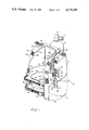
FIG. 1 shows a perspective view of the buoyancy compensator of this invention.
FIG. 2 shows a view of the shoulder straps in the direction of lines 2--2 with the covering sleeve removed.
FIG. 3 shows a view of the tank securement straps as shown in the direction of lines 3--3 of FIG. 1.
DESCRIPTION OF THE PREFERRED EMBODIMENTS
Looking at FIG. 1, it can be seen that a buoyancy compensator 10 is shown having a back area or portion 12 and two side areas or waist portions 14 and 16 which generally circumscribe a user's waist. The side areas or waist areas 14 and 16 are joined by a belt 18 at the bottom and a belt 20 toward the top. The two respective belts 18 and 20 are adjustable and can be linked by means of the buckles, respectively 22 and 24.
Interiorly of the back area 12 and waist areas 14 and 16 is an enlarged elastomeric belt 28 affixed by loops to belt 18. The belt 28 is formed of elastomeric foam such as wetsuit material and is joined by means of a hook and loop or pile material known under the trademark of Velcro at the front thereof in the area 32. The belt 28 is capable of expanding and contracting based upon the pressure due to the fact that it is made of a cellular foam which expands and contracts based upon pressure surrounding it in the ambient environment. The belt 28 is held to the buoyancy compensator by loops such as loop 36 attached to waist area 16 in connection with the belt 18. The belt 28 interiorly circumscribes the back 12 and waist areas 14 and 16 so as to allow for the adjustable depth compensation of the belt 28 as to its size. The compensation is caused by the elastomeric material expanding and contracting and at the same time holding the buoyancy compensator to a user's waist in snug relationship by interconnecting it with the belt 18 and loops 36.
The buoyancy compensator is made with an outer material with a bladder interiorly thereof. However, it can be made in a single walled configuration wherein the outer material serves both as the bladder and the reinforcing material holding the buoyancy compensator in its general configuration.
The buoyancy compensator has a tank 40 attached thereto. The tank 40 has a neck 42 with a valve configuration 44 for connection to a first stage regulator for regulating the gas to an intermediate pressure and providing the various intermediate pressure gases and high pressure gases for a diver.
The buoyancy compensator also incorporates an oral inflator 46 having a mouthpiece 48 and a valve button 50 for allowing one to fill the buoyancy compensator by depressing the valve button 50 and blowing into the mouthpiece 48. This causes air to be delivered through the tube 56 to an inlet fitting 58.
In addition to the foregoing features, the inflator 46 can be connected to a source of pressurized breathing gas for allowing power inflation of the interior of the buoyancy compensator.
An overinflation valve is incorporated in the fitting 58 or can be incorporated in any other place to relieve pressure upon pressure being developed within the buoyancy compensator either due to changes through ambient conditions or through overinflation by means of the power inflator. Also, a dumping valve mechanism is shown, namely, valve assembly 60. The valve assembly 60 incorporates a handle or pull member 62 for relieving pressure within the buoyancy compensator so that various pressure configurations and buoyancy can be trimmed by means of either filling or dumping gas through the dump valve 60.
A side pocket 66 is incorporated with a flap 68 for holding diving equipment therein. This is attached to the side of the buoyancy compensator and can either be stitched or held there by adhesive or formed in any other suitable manner.
The tank 40 is held to the buoyancy compensator by means of a backpack that is partially, shown, namely backpack 70. Backpack 70 as seen through lines 3--3 has been sectioned and shown in FIG. 3. The backpack allows for the tank 40 to be held on the buoyancy compensator while at the same time seating the backpack in adjoining relationship to the buoyancy compensator and holding it in situ therewith.
The backpack has slots 74 and 76 which receive a strap 78 passing therethrough. The strap 78 can be of a broad band configuration as shown in the lower area of the buoyancy compensator or it can be of a narrow band configuration shown above strap 78. The strap has a sleeve member 80 surrounding it which serves to seat against the tank 40 to hold it in place. One end of the strap, namely end 82 is looped through a buckle member 84. The strap extends from the loop 82 and terminates with a loop and pile fitting 88 known in the trade as Velcro. The strap 78 as it passes through the loop can be seen passing through a first portion and then around the end of a bail 90 of the buckle 84. The strap is then looped up under the bail 90 and extends as strap portion 92 around an internal portion of the buckle 84 and is finally looped around the end at loop 94 to extend over the top of the loops to the securement means 88 in the form of the loop and pile or Velcro attachment means for the end or tongue of the strap 78. The bail 90 is allowed to pivot upwardly and downwardly and is secured by a frictional engagement within a slot 100 so as to allow it to secure the strap 78 in a tightened configuration around the tank 40 for securing it to the backpack 70.
Looking more particularly at FIG. 2 it can be seen wherein an upper shoulder area 104 is shown and the terminal portion of the side or waist portion 14 is shown. The upper shoulder portion 104 is matched with a second shoulder portion 106 to allow the buoyancy compensator to seat comfortably across a user's shoulders while at the same time holding the load of the tank. The shoulder portions 104 and 106 are attached respectively to the interior of the side portions of the buoyancy compensator 14 and 16 by attachment tabs 110 stitched thereto which serve to secure a belt or strap 112 to the lower portion 14 or side walls 14 and 16. Belt or strap 112 extends upwardly through a first buckle bail or eyelet 114 and around the end of a second bail or eyelet 116. Belt 112 extends downwardly again through the bail 114 terminating in a stitched loop 118 that is provided by a stitched overlapped end that receives a handle or pull in the form of a loop 120.
An upper strap or belt 140 is stitched to the shoulder member 104 and is held thereto by means of a stitching tab 142. The upper strap or belt 140 is looped around both of the ends of the eyelets, buckle or bail members 114 and 116, firstly going through the opening of the buckle member 116 and then around the end of the buckle, bail eyelet, or belt member 114. Attached at the other end of the belt or buckle member 114 is a looped portion of a belt 146. Specifically, a looped portion 148 is shown looped around the end of eyelet or buckle member 114 which terminates in a second looped handle or pull 152 shown therewith.
The looped handle 152 can be pulled upwardly for adjustment in the direction of arrow U as shown in order to loosen the entire belt and buckle configuration due to the weight of the buoyancy compensator with the load of the cylinder 40. On the other hand, when handle or loop member 120 is pulled downwardly in the direction of arrow D it tends to cinch up or tighten the relationship between the two respective belts 140 and 112 thereby bringing the shoulder area 106 into closer proximation to the side area 16 and in like manner shoulder member 104 to side area 14. It should be kept in mind that both eyelets, loops, or buckle members 114 and 116 or loop members provide free passage therethrough.
The foregoing configuration is surrounded by sleeves or covers 160 and 162. These sleeves 160 and 162 hold the respective belts and buckle members in the cinched condition so as to allow the binding of the belts and the loops 114 and 116 to operate in the manner as shown hereinbefore. However, with the sleeves 160 and 162 or any other type of member analogous to sleeves 160 and 162, the same kind of action can take place insofar as tightening by pulling downwardly on handle 120 or loosening by pulling upwardly on handle 152.
The operation of the foregoing allows the downward or loading tension on belts 140 and 112 to provide a bight through the loops 114 and 116 in engagement with the loop of the belt 112 passing therearound. Thus, any means suitable to provide a bight on the two respective belts 112 and 140 through the loops, eyelets or buckle members 114 and 116 can be utilized whether it be an overlying sleeve as shown or any other suitable means including tangs or engagement means in the buckle, loops or members 114 and 116.
It should be understood that the weight on the buoyancy compensator is usually sufficient to place a bight on the belt 112 through buckle loops or eyelets 114 and 116. Thus, the tension by the weight of the system maintains the position of the belts until the bight is relieved by handle 152 removing the bight through its upward lift to permit the loop of belt 112 to pass over eyelet 116.
Attached to sleeve 162 is a looped pile 162 which can secure a pile ring surrounding the oral inflation tube of oral inflator 165. This is in the form of Velcro attachment means 163 and 165 so as to secure the oral inflator to the sleeve 162.
Thus, in summation, in showing the action of the foregoing, a tightening of the buoyancy compensator across one's shoulders is effectuated by pulling down in the direction of Arrow D. Pulling up in the direction of Arrow U loosens the shoulder areas 104 and 106 with respect to the side panel members 14 and 16. The foregoing will be seen as an advance over the art in light of the following claims and in view of the other elements of the buoyancy compensator hereof.