US4735003A - Protective toe cap for footwear - Google Patents
Protective toe cap for footwear Download PDFInfo
- Publication number
- US4735003A US4735003A US06/930,962 US93096286A US4735003A US 4735003 A US4735003 A US 4735003A US 93096286 A US93096286 A US 93096286A US 4735003 A US4735003 A US 4735003A
- Authority
- US
- United States
- Prior art keywords
- roof region
- toe cap
- region
- metallic
- roof
- Prior art date
- Legal status (The legal status is an assumption and is not a legal conclusion. Google has not performed a legal analysis and makes no representation as to the accuracy of the status listed.)
- Expired - Lifetime
Links
Images


Classifications
-
- A—HUMAN NECESSITIES
- A43—FOOTWEAR
- A43B—CHARACTERISTIC FEATURES OF FOOTWEAR; PARTS OF FOOTWEAR
- A43B23/00—Uppers; Boot legs; Stiffeners; Other single parts of footwear
- A43B23/08—Heel stiffeners; Toe stiffeners
-
- A—HUMAN NECESSITIES
- A43—FOOTWEAR
- A43B—CHARACTERISTIC FEATURES OF FOOTWEAR; PARTS OF FOOTWEAR
- A43B23/00—Uppers; Boot legs; Stiffeners; Other single parts of footwear
- A43B23/08—Heel stiffeners; Toe stiffeners
- A43B23/081—Toe stiffeners
- A43B23/086—Toe stiffeners made of impregnated fabrics, plastics or the like
- A43B23/087—Toe stiffeners made of impregnated fabrics, plastics or the like made of plastics
-
- A—HUMAN NECESSITIES
- A43—FOOTWEAR
- A43C—FASTENINGS OR ATTACHMENTS OF FOOTWEAR; LACES IN GENERAL
- A43C13/00—Wear-resisting attachments
- A43C13/14—Special attachments for toe-caps; Protecting caps for toe-caps
Definitions
- the present invention relates to footwear, and is concerned in particular with the shoes, boots, and overshoes which contain toe caps that structurally reinforce the toe of the footwear and protect the wearer from injury caused by objects which fall or roll onto the toe.
- the cap must be hollow in order to envelop the toes of the wearer in a protective pocket, and the hollow pocket of the cap must have the same approximate volume and shape as an ordinary shoe in the toe area for fit and comfort.
- the toe cap must be lightweight, and for practicality and esthetics, the toe cap should fit within the general contours of a shoe toe.
- Plastic toe caps offer a number of advantages over steel caps. Plastic toe caps are lighter in weight which results in less fatigue to the wearer during extended periods of use. Plastics also have much lower heat conductivity, and therefore they offer much more comfort to the wearer in cold weather and reduce the danger of frostbite.
- Plastics in general are not ductile, and as a result, when they are stressed beyond their limits, they flex first to a limited degree and then fracture. When the load or weight is removed from the safety shoe, the toes of the wearer are immediately freed from the stress.
- Plastic toe caps are also nonmagnetic and can be rendered electrically conductive or nonconductive as desired. Plastic caps do not corrode and hence are not affected by moisture and perspiration.
- a primary concern when a steel toe cap is replaced by plastic is the adequacy of the structural reinforcement since substantially all plastics have tensile and compressive strengths that are less than those for steel. Recognized standards exist both in the United States and foreign countries for testing and acceptance of toe caps. In the United States, the toe caps must meet compression and impact tests according to ANSI Standard Z41-1983, of the American National Standards Institute, New York, N.Y. In Europe, toe caps are tested for impact resistance according to DIN Standard 4843. Prior to the development of the toe cap of the present invention, it is believed that no plastic toe cap produced on a commercial scale complied with such standards. It is accordingly an object of the present invention to provide a plastic toe cap for footwear which provides all of the recognized advantages of plastic toe caps in a design that is capable of meeting the applicable strength standards.
- the present invention resides in a non-metallic toe cap for use in footwear to provide structural reinforcement of the toe area against compression and impact loading.
- the toe cap is comprised by a shell body made from a plastic material and has the shape of a shoe toe with a rearward facing opening at the entrance of the toe pocket.
- a roof region of the shell body extends forwardly to a front wall region and laterally to lateral wall regions disposed at opposite sides of a central plane.
- the lateral and front wall regions project upwardly from a generally planar base that is shaped to conform to the generally elliptical front part of the shoe sole, and the wall regions join the roof region with smoothly contoured curves to form a continuous and rounded shell body.
- the roof region of the toe cap includes means for shifting the stresses and fracture point under compression and impact loads outwardly from the central plane to the wall regions.
- the wall regions which project generally vertically upward support such loads more satisfactorily and at higher load levels so that a safe and more comfortable toe cap is obtained.
- the means for shifting the loads from the roof to the wall regions is comprised by means for rendering the roof region of the cap flexible so that the applied loads are distributed elsewhere and are supported primarily by the wall sections.
- the means providing the flexibility may include a series of grooves extending longitudinally through the roof of the wall region, a reduced wall section in the roof region, a different plastic material having a lower modulus of elasticity than the rest of the toe cap and combinations of these means.
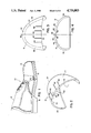
- FIG. 1 is a side elevation view of a safety shoe with the toe portion cut away to illustrate the toe cap of the present invention.
- FIG. 2 is a perspective view of the toe cap illustrated in the shoe of FIG. 1.
- FIG. 3 is a top plan view of the toe cap.
- FIG. 4 is a rear elevation view of the toe cap.
- FIG. 5 is a side elevation view of the toe cap sectioned along the central fore and aft plane.
- FIG. 6 is another rear view of the cap and shows the reaction of the cap to a compression load.
- FIG. 7 is a perspective view of another embodiment of the toe cap.
- FIG. 8 is a rear elevation view of the toe cap in FIG. 7.
- FIG. 9 is a rear elevation view of still another embodiment of the invention.
- FIG. 10 is a chart illustrating the compression and impact tests on various toe caps.
- FIG. 11 is a rear elevation view of still another embodiment of the invention.
- FIG. 1 illustrates a safety shoe, generally designated 10, with an internal non-metallic toe cap 12 in accordance with the present invention.
- the cap 12 is installed in the toe area to provide structural reinforcement of the shoe against compression and impact loads that arise from objects falling or shifting onto the toe area.
- the toe cap 12 may also be installed in other types of footwear, such as boots and toe protectors that slip over the shoe or toe areas of the shoe for safety and protection.
- the safety shoe 10 is of a conventional construction having leather, rubber, or synthetic uppers 14, a heel 16, a hard rubber or leather outer sole 18, a cushioned insole 20, and other comfort features, such as internal lining and collars.
- the shoe may in addition have a reinforced heel area, protective shanks in the sole for intrusions from below, and other safety features as desired.
- the toe cap 12 is mounted on top of the sole 18 and within the contours of the upper 14 in the toe area.
- FIGS. 2-5 illustrate non-metallic the toe cap 12 of the present invention in greater detail.
- the toe cap is basically a shell body that is constructed entirely from plastic material.
- the term "plastic” applies to a variety of synthetic materials including both thermoplastic and thermosetting resins with and without fiber reinforcement.
- suitable thermoplastic resins are polyvinylchloride (PVC), ABS (a polymerized mixture of styrene, acrylonitrile, and nitrile rubber), polycarbonates, polyethylene, polyethylene terephthalate, polypropylene, polyurethane, polyphenylene sulfide, polyetheretherketone, polyetherimide, polyamide-imide, and blends of these plastics.
- suitable thermosetting resins which can be used with selected reinforcing fibers and fillers include phenolics, polyesters, epoxies, polyamides, and polyacrytamates.
- plastic materials referred to above may be reinforced with glass fibers and fibers of carbon, graphite, and Kevlar.
- the toe caps 12 of the present invention are made by molding in various fashions. Compression molding, injection molding, or resin transfer processes, as well as injectioncompression molding and pressure forming are suitable for the various resins discussed above. When resin reinforcement is desired, the injection molding technique should be avoided unless precautions are taken to prevent fiber length degradation and development of generally parallel fiber orientation in the finished part.
- One example of the toe cap construction in accordance with the present invention was made from a polyphenylene sulfide (PPS) plastic with glass reinforcement.
- PPS polyphenylene sulfide
- the PPS plastic with glass fiber reinforcement was first preheated in an oven system as a precut preform of proper weight, then hot-formed under pressure in a cool compression mold to the final configuration.
- the fiber reinforcement was 40% by weight of the finished product and used swirl mat fiberglass.
- toe cap construction in accordance with the present invention was made with a polyurethane plastic with glass fiber reinforcement preheated in an extruder or plasticizer.
- a slug of the material of appropriate weight was then placed in the compression mold and formed under pressure to the final configuration of the toe cap.
- the length of the glass fibers in the initial charge ranged between half-inch to two inches but the length of the longer fibers was reduced as the material passed through the plasticizer to a range of one-quarter inch to one inch.
- the volume ratio of polymer to glass fiber was approximately 60%. Higher percentages including 100% plastic without reinforcing fibers are also possible.
- the toe cap 12 of FIGS. 2-5 is a unitary structure having a hollow shell body in the general shape of a shoe toe.
- the body has a rearward-facing opening 26 for insertion and withdrawal of the toes when the shell is mounted in the shoe and defines the toe pocket.
- the shell body includes a roof region 30 at the top of the toe cap, a front wall region 32 at the forward part of the toe cap, a right wall region 34, and a left wall region 36.
- the left and right wall regions 34,36 are disposed generally equidistant from a longitudinal central plane 38 along which the toe cap is sectioned in FIG. 5.
- the various roof and wall regions are generally outlined by the dashed lines in FIG. 3, but it should be understood that the precise boundary line of each region is not critical, and all of the regions are joined together by smooth continuous curves to fit within the toe of a shoe or other footwear with an esthetically pleasing external shape and an internal shape conforming to the last or form on which shoes are constructed.
- the wall regions 32, 34, and 36 project vertically upward from a generally planar base 37, as is clear from the illustrations in FIGS. 4 and 5, and they conform generally to the front part of the shoe sole, as is apparent from FIGS. 2 and 3.
- the bottom edges of the wall regions are curved inwardly as shown in order to provide a wide seat for resting the toe cap 12 against the shoe sole.
- the toe cap can be glued or otherwise secured to the sole and the upper, or the cap can simply be held in place within the toe of the shoe by the surrounding material.
- Recesses in the sole can be provided as well to accept the lower edges of the wall regions, and stitching between the upper and a lining within the shoe can be used to hold the toe cap in place.
- the roof region 30 extends horizontally with a generally arcuate shape in both longitudinal and lateral planes. As shown in FIGS. 4 and 5, the uppermost point of the arcuate shape lies at a position slightly in front of the rear edge of the toe cap and in the central plane. The uppermost point is positioned strategically to make first contact with the objects that fall or slide onto the shoe toe.
- the toe cap 12 of FIGS. 2-5 does not contain a floor section, since the shoe sole 18 normally closes the bottom of the toe pocket in the shoe.
- the toe cap 12 can be constructed with a floor section if no other sole reinforcement is provided, and in that event, the wearer of the shoe would be protected from objects which would otherwise pierce the shoe sole from below and possibly cause injury to the toes.
- the toe cap 12 is designed with a roof region that includes means for shifting load stresses outwardly away from the central plane 38 to the wall regions 32, 34, and 36.
- the illustrated means for shifting comprises a plurality of grooves 40, 42, 44, 46, 48, and 50 which extend longitudinally in the roof region from the rearwardmost edge 52 to positions intermediate the front and rear edge of the cap.
- the number and length of the grooves varies depending upon the design of the toe cap. In wider caps a greater number of grooves are distributed across the greater expanse of a roof region, and in caps having greater front-to-rear dimensions, the grooves are longer to achieve the desired load shifting as explained further below.
- the grooves can be placed solely on the interior or exterior surfaces of the shell body; however, with high crown caps, the grooves are preferably located on both surfaces.
- the grooves penetrate only partially into the roof section from the exterior and interior surfaces for the purpose of rendering the roof region more flexible to loads that are applied to the top of the toe cap.
- Such flexibility has the effect to shifting the resistance or forces reacting to the loads from the roof region to the wall regions which, being vertically oriented, are more capable of supporting the loads without bending and fracturing.
- FIG. 6 illustrates the deflection that occurs in the novel toe cap 12 when a load L is placed on the roof region 30.
- the unloaded, undeflected position of the roof region is illustrated in phantom.
- the solidline deflected position indicates the larger degree of deflection and flattening that the roof region undergoes, and the consequential spreading of the load laterally over the roof region 30 toward the walls 34,36.
- critical stresses from the load L are relieved in the central part of the arcuate roof region 30 and are are shifted from the central or apex part outwardly toward the wall regions 34 and 36.
- a similar shifting toward the front wall 32 occurs simultaneously.
- FIG. 10 illustrates the results of compression and impact tests that have been compiled for several caps made from a plastic material.
- Specimen A defines a cap made from a fiber reinforced plastic having the same general configuration as that illustrated in the drawings of this application but with a generally uniform wall thickness throughout. The tests were conducted to ensure compliance with the American National Standard (ANSI Z41-1983) for both compression and impact loading. Under this Standard, failure occurs when the toe cap collapses to such a degree that a half-inch feeler gauge (steel rod) will not slide in and out of the opening 26 at the rear edge of the cap.
- ANSI Z41-1983 American National Standard
- the top and bottom limits of the box represent the upper and lower load limits at which several specimens of the A type failed, and the number and data point at the center of the box represents the average failure load for the specimens.
- the load level labeled 68 in the figure represents the compression load level that ensures acceptance under the referenced ANSI Standard Z41.
- the data points 70,72,74, and 76 represent the results for impact load tests to determine if the caps are in compliance with the referenced ANSI Standard.
- the fraction numerals represent the height of the toe pocket within the toe gap in inches after the test, and the level that ensures acceptance according to ANSI Standard Z41-1983 is labeled 78.
- Specimen B was structurally similar to specimen A but shows somewhat improved results at box 62 and point 72 in comparison to Specimen A due to process improvements that assured controlled fiber length and more uniform fiber distribution in the finished part. While these improvements raised the level of both the compression and impact results, the acceptance levels 68 and 78 were not reached.
- Specimen C was constructed from a fiber reinforced plastic with a flexible roof region established by grooves as shown in FIGS. 2-5. It is apparent from the results (64,74) that this specimen consistently passed both the impact and compression tests in accordance with the ANSI Standard. The compression test results for Specimen C are not only higher than that for any other specimen, they are also more repeatable, which is indicated by a smaller separation between the upper and lower limits of the box 64.
- FIGS. 7 and 8 illustrate a toe cap 80 which constitutes a further embodiment of the present invention.
- the toe cap 80 is constructed of plastic materials and has the same shape as the toe cap 12 in FIGS. 1-5.
- the principal difference in the body structure resides in the formation of a compound structure in which the roof region 82 is a piece distinctly different from the wall regions 84.
- the toe cap 80 does not have an integral shell body, but a shell body consisting of two separate pieces.
- the roof region 82 can be joined to the wall regions 84 by mechanical means such as a snap-type fitting or it can be bonded in place with epoxy or other resins compatible with the plastic material of the roof and wall.
- the toe cap 80 functions in a manner similar to the toe cap 12 in that the roof region 82 is designed with sufficient flexibility to cause the load stresses on top of its arcuate shape to be shifted outwardly away from the central plane to the wall regions 84.
- Such flexibility is achieved by constructing the roof region 82 with a thinner wall section that affords such flexibility or with materials that have a lower modulus of elasticitiy or both.
- the roof region 82 can be constructed from a different type of plastic than the wall region 84 or the plastic for the wall region can be fiber reinforced while the roof region 82 is without fiber reinforcement.
- FIG. 9 discloses another toe cap 90 which constitutes still a further embodiment of the present invention.
- the toe cap 90 is similar in shape to the embodiments 12 and 80 discussed above and contains a roof region 92 and a wall region 94.
- the cap 90 has an integral or one-piece construction and is made entirely from a single type of plastic material with limited or no fiber reinforcement.
- the cap 90 in accordance with the present invention achieves a flexible roof region 92 by reducing the wall thickness t of the arcuately shaped roof region so that compression and impact loads will more easily deflect the roof region and cause the fracture stresses to shift or occur first in the wall regions rather than the roof region as discussed above in connection with FIG. 6. For example, if the wall regions have a thickness of 0.25 inches, the roof region would have a reduced wall thickness of 0.05 inch.
- FIG. 11 discloses still another toe cap 100.
- the roof region 30 of the toe cap 100 is made flexible either by grooves 104 such as the grooves described in the toe cap 12 or by material or thickness controls as indicated in the toes 80 and 90. Such flexibility allows the roof region to flex under load which simultaneously transfers the load to the wall regions 32, 34 and 36.
- the toe cap 100 differs principally from the toe cap 12 in that the planar base 101 of the cap contains a projection or ridge 102 that extends downwardly away from the base and runs at least along the bottom side of the sidewall regions 34, 36 and preferably along the front wall region as well.
- the projection 102 rests on the sole of the finished shoe shown in FIG. 1 and penetrates into the sole under compression or impact loading to thereby engage the sole and prevent the lateral wall regions 34 and 36 from spreading outwardly at the bottom.
- Such spreading of the lateral walls under load reduces the strength of the toe cap and height of the toe cap in the central plane 38 and allows the roof 30 to collapse by an impermissible amount.
- the projection 102 prevents the spreading of the walls by locking the base of the walls to the underlying shoe sole. In effect the sole closes the opening across the bottom of the molded cap which increases the shell strength of the cap. Therefore, load transfer from the roof region to the wall regions can take place without significant loss of clearance between the roof and sole.
- the toe cap 100 also illustrates the grooves 104 at an asymmetric position with respect to the central plane 38 for introducing the required flexibility into the roof section. This positioning illustrates the fact that flexibility can be designed into the different sections of the roof region as needed to provide a load transfer which is most suitable for a particular toe design.
- a toe cap which can be formed entirely from a plastic material and have strength characteristics which allow the lateral and forward wall regions to support compression and impact loads that would normally fracture the roof region of the cap near the central longitudinally extending plane.
- the roof region of the cap is designed to be flexible so that under load, fracture level stresses are shifted to the lateral and forward walls of the cap. Because the walls are generally vertical and capable of supporting higher compression and impact load levels before fracture occurs, a stronger toe cap is formed.
Abstract
Description
Claims (23)
Priority Applications (7)
| Application Number | Priority Date | Filing Date | Title |
|---|---|---|---|
| US06/930,962 US4735003A (en) | 1986-03-25 | 1986-11-12 | Protective toe cap for footwear |
| CA000532282A CA1277136C (en) | 1986-03-25 | 1987-03-17 | Protective toe cap for footwear |
| AT87302310T ATE83361T1 (en) | 1986-03-25 | 1987-03-18 | TOE CAP FOR SHOES. |
| EP87302310A EP0239313B1 (en) | 1986-03-25 | 1987-03-18 | A protective toe cap for footwear |
| DE8787302310T DE3783062D1 (en) | 1986-03-25 | 1987-03-18 | TOE CAP FOR SHOES. |
| NO871182A NO164877C (en) | 1986-03-25 | 1987-03-23 | LIGHT OF PLASTIC MATERIAL FOR APPLICATION IN SKOTOEY. |
| KR1019870002727A KR910001751B1 (en) | 1986-03-25 | 1987-03-25 | Protective toe cap for shoes |
Applications Claiming Priority (2)
| Application Number | Priority Date | Filing Date | Title |
|---|---|---|---|
| US84370386A | 1986-03-25 | 1986-03-25 | |
| US06/930,962 US4735003A (en) | 1986-03-25 | 1986-11-12 | Protective toe cap for footwear |
Related Parent Applications (1)
| Application Number | Title | Priority Date | Filing Date |
|---|---|---|---|
| US84370386A Continuation-In-Part | 1986-03-25 | 1986-03-25 |
Publications (1)
| Publication Number | Publication Date |
|---|---|
| US4735003A true US4735003A (en) | 1988-04-05 |
Family
ID=27126434
Family Applications (1)
| Application Number | Title | Priority Date | Filing Date |
|---|---|---|---|
| US06/930,962 Expired - Lifetime US4735003A (en) | 1986-03-25 | 1986-11-12 | Protective toe cap for footwear |
Country Status (6)
| Country | Link |
|---|---|
| US (1) | US4735003A (en) |
| EP (1) | EP0239313B1 (en) |
| KR (1) | KR910001751B1 (en) |
| CA (1) | CA1277136C (en) |
| DE (1) | DE3783062D1 (en) |
| NO (1) | NO164877C (en) |
Cited By (46)
| Publication number | Priority date | Publication date | Assignee | Title |
|---|---|---|---|---|
| US5210963A (en) * | 1991-11-26 | 1993-05-18 | Harwood John M | Molded plastic toe cap |
| DE4320312A1 (en) * | 1992-07-02 | 1994-01-13 | Yoshida Kogyo Kk | Fibre reinforced toe cap for safety shoe - is made of plastics and has border curving inwards from lower part of front end part and opposite facing sides |
| US5457898A (en) * | 1994-03-24 | 1995-10-17 | Fortin; Gilles | Metatarsal guard for safety shoe |
| WO1997019609A1 (en) * | 1995-11-28 | 1997-06-05 | Norman William Macleod | Toe caps for footwear |
| US5666745A (en) * | 1995-11-06 | 1997-09-16 | Harwood; John M. | Molded plastic toe cap for shoes |
| US5809666A (en) * | 1995-11-06 | 1998-09-22 | Harwood; John M. | Molded plastic toe cap for shoes |
| US6159589A (en) * | 1995-12-22 | 2000-12-12 | H.H. Brown Shoe Company | Injection molding of long fiber reinforced thermoplastics |
| WO2001000392A1 (en) * | 1999-06-28 | 2001-01-04 | Asahi Fiber Glass Company, Limited | Process for producing a fiber-reinforced thermoplastic resin molded product and product thereby produced |
| DE20106350U1 (en) * | 2001-04-11 | 2002-08-14 | Uvex Arbeitsschutz Gmbh | Protective shoe, safety shoe or boot |
| US20020108270A1 (en) * | 2000-12-18 | 2002-08-15 | Williams Jason L. | Plastic toe cap and method of making |
| DE10114560A1 (en) * | 2001-03-24 | 2002-09-26 | Uvex Arbeitsschutz Gmbh | Protective shoe, safety shoe or boot |
| US6598323B1 (en) * | 1997-12-05 | 2003-07-29 | Robert M. Gougelet | Toe protectors |
| US20040139630A1 (en) * | 2003-01-21 | 2004-07-22 | Gerwin Stephen C. | Turf management safety shoe |
| US20040221489A1 (en) * | 2003-05-06 | 2004-11-11 | Linear International Footwear Inc. | Composite plate |
| EP1502518A1 (en) * | 2003-08-01 | 2005-02-02 | Mecelec | Toe cap for safety shoe and shoe with such toe cap |
| US20050039350A1 (en) * | 2003-05-06 | 2005-02-24 | Linear International Footwear Inc. | Composite plate |
| US20050060914A1 (en) * | 2003-07-22 | 2005-03-24 | Fuerst Rory W. | Footwear having an enclosed and articulated toe |
| US20050144809A1 (en) * | 2004-01-07 | 2005-07-07 | Yang Willy H. | Composite reinforced toecap and a method of making the same |
| US20080005932A1 (en) * | 2006-07-05 | 2008-01-10 | Vladlen Zitin | Sporty, positionable, strength combining toe separator |
| US20090071036A1 (en) * | 2007-09-13 | 2009-03-19 | Nike, Inc. | Article of Footwear Including a Composite Upper |
| US20090145006A1 (en) * | 2007-12-11 | 2009-06-11 | Baffin Inc. | Safety footwear |
| US20090300944A1 (en) * | 2008-06-06 | 2009-12-10 | Daunielle Miller | Protective safety shoe insert |
| US20100325817A1 (en) * | 2007-07-31 | 2010-12-30 | Paul Siragusa | Wearable Shoe Tree |
| US20110093997A1 (en) * | 2009-10-28 | 2011-04-28 | Vibram Sp.A. | Bomb toe cap and method of forming the same |
| US20120167419A1 (en) * | 2009-07-14 | 2012-07-05 | Treksta, Inc. | Toe cap for footwear, and outsole integrated with toe cap |
| US20120255200A1 (en) * | 2011-04-08 | 2012-10-11 | Mizuno Corporation | Upper Structure for a Shoe |
| WO2014007818A1 (en) * | 2012-07-05 | 2014-01-09 | Honeywell International Inc. | Injected protective toe cap |
| US20150040440A1 (en) * | 2013-08-07 | 2015-02-12 | ProtecTozz LLC | Toe protector for athletic footwear having removable cleats |
| USD787788S1 (en) * | 2015-12-08 | 2017-05-30 | Rocky Brands, Inc. | Footwear toe cap |
| USD793678S1 (en) * | 2015-11-20 | 2017-08-08 | Joseph Burns | Toe guard |
| US9826799B2 (en) | 2013-03-14 | 2017-11-28 | Nike, Inc. | Uppers and articles incorporating same |
| USD809772S1 (en) * | 2016-09-15 | 2018-02-13 | Vijai Ramsumeer | Women's open toe shoe insert kit |
| US20190000178A1 (en) * | 2017-06-30 | 2019-01-03 | Chih Jen Tsai | Shoe cover |
| CN109393633A (en) * | 2017-08-16 | 2019-03-01 | 渥弗林户外用品公司 | Footwear and correlation technique with protectiveness toe protector |
| US20190191816A1 (en) * | 2017-12-22 | 2019-06-27 | Bauer Hockey Ltd. | Skate |
| USD903990S1 (en) | 2016-11-01 | 2020-12-08 | Lisias Ransan | Footwear component |
| USD912375S1 (en) | 2018-11-01 | 2021-03-09 | Lisias Ransan | Footwear component |
| USD920642S1 (en) | 2019-12-03 | 2021-06-01 | Lisias Ransan | Ballet pointe shoe |
| USD927841S1 (en) * | 2019-10-14 | 2021-08-17 | James Edward O'Leary | Detachable vamp |
| WO2022020530A1 (en) * | 2020-07-22 | 2022-01-27 | The North Face Apparel Corp. | Multi-function sneaker |
| US11266205B2 (en) * | 2018-03-15 | 2022-03-08 | Shoe-Vital LLC | Wearable shoe shaper |
| US11278080B2 (en) | 2019-01-19 | 2022-03-22 | Lisias Ransan | Ballet pointe shoe having toe platform with malleable bumper |
| US20220125155A1 (en) * | 2020-10-23 | 2022-04-28 | Tbl Licensing Llc | Strain-Hardened Safety Toe For Footwear |
| USD977230S1 (en) | 2020-07-23 | 2023-02-07 | The North Face Apparel Corp. | Footwear |
| USD1014682S1 (en) | 2017-12-22 | 2024-02-13 | Bauer Hockey Llc | Toe cap for a skate |
| USD1014943S1 (en) * | 2021-08-09 | 2024-02-20 | Tbl Licensing Llc | Toe cap for footwear |
Families Citing this family (4)
| Publication number | Priority date | Publication date | Assignee | Title |
|---|---|---|---|---|
| GB2264221A (en) * | 1992-02-12 | 1993-08-25 | Wyatt Gates | Reinforcement device for footwear |
| CA3026408C (en) | 2016-06-02 | 2022-09-20 | The North Face Apparel Corp. | Intelligent toe cap |
| IT201900020742A1 (en) * | 2019-11-11 | 2021-05-11 | Alustrategy S R L | Toe cap for footwear and related footwear |
| DE102022202833A1 (en) | 2022-03-23 | 2023-09-28 | Uvex Arbeitsschutz Gmbh | Protective shoe |
Citations (15)
| Publication number | Priority date | Publication date | Assignee | Title |
|---|---|---|---|---|
| US1859452A (en) * | 1928-05-16 | 1932-05-24 | United Shoe Machinery Corp | Shoe stiffener and shoe |
| US2079237A (en) * | 1936-03-26 | 1937-05-04 | Arthur R Allard | Safety shoe |
| US2091223A (en) * | 1935-10-08 | 1937-08-24 | Robert Malcom | Toe-cap |
| GB487761A (en) * | 1938-02-14 | 1938-06-24 | Henry Heginbotham | Improvements in or relating to protectors for the toes of boot and shoe uppers |
| US2392867A (en) * | 1944-08-11 | 1946-01-15 | Nancy F Stoner | Safety protector for shoes |
| GB678031A (en) * | 1950-03-09 | 1952-08-27 | Brynmawr Boot Makers Ltd | Improvements in or relating to footwear |
| US2795868A (en) * | 1955-11-15 | 1957-06-18 | Endicott Johnson Corp | Liner for metal toe boxes |
| US3407518A (en) * | 1966-04-15 | 1968-10-29 | Interco Inc | Shoe with toe and instep guard assembly |
| US3593438A (en) * | 1969-07-30 | 1971-07-20 | Bata Shoe Co | Spread-resistant metal toe for safety shoes |
| GB1284736A (en) * | 1969-05-01 | 1972-08-09 | Gkn Group Services Ltd | Improvements in or relating to footwear |
| US3950865A (en) * | 1975-04-08 | 1976-04-20 | Bata Shoe Company, Inc. | Safety box toe |
| EP0021612A1 (en) * | 1979-06-08 | 1981-01-07 | Firth Cleveland Engineering Limited | Protective toe cap |
| FR2525443A1 (en) * | 1982-04-23 | 1983-10-28 | Agulhon Michel | Protective toe cap for safety shoe - which has shell open at bottom and with back made of polycarbonate with mineral fibres |
| EP0095061A1 (en) * | 1982-05-26 | 1983-11-30 | ESJOT-WERKE Schiermeister & Junker | Steel toe-cap for safety shoes |
| US4575953A (en) * | 1983-03-10 | 1986-03-18 | Gerhard Hetzel | Safety shoe with toe protecting cap |
Family Cites Families (3)
| Publication number | Priority date | Publication date | Assignee | Title |
|---|---|---|---|---|
| GB2071989B (en) * | 1980-03-21 | 1984-11-28 | Britton Ltd G B | Protective toe caps for footwear |
| GB2138272B (en) * | 1980-03-21 | 1985-05-01 | Britton Limited G B | Protective toe caps |
| EP0100181A1 (en) * | 1982-07-28 | 1984-02-08 | Imperial Chemical Industries Plc | Protective toe caps |
-
1986
- 1986-11-12 US US06/930,962 patent/US4735003A/en not_active Expired - Lifetime
-
1987
- 1987-03-17 CA CA000532282A patent/CA1277136C/en not_active Expired - Lifetime
- 1987-03-18 DE DE8787302310T patent/DE3783062D1/en not_active Expired - Lifetime
- 1987-03-18 EP EP87302310A patent/EP0239313B1/en not_active Expired - Lifetime
- 1987-03-23 NO NO871182A patent/NO164877C/en unknown
- 1987-03-25 KR KR1019870002727A patent/KR910001751B1/en not_active IP Right Cessation
Patent Citations (15)
| Publication number | Priority date | Publication date | Assignee | Title |
|---|---|---|---|---|
| US1859452A (en) * | 1928-05-16 | 1932-05-24 | United Shoe Machinery Corp | Shoe stiffener and shoe |
| US2091223A (en) * | 1935-10-08 | 1937-08-24 | Robert Malcom | Toe-cap |
| US2079237A (en) * | 1936-03-26 | 1937-05-04 | Arthur R Allard | Safety shoe |
| GB487761A (en) * | 1938-02-14 | 1938-06-24 | Henry Heginbotham | Improvements in or relating to protectors for the toes of boot and shoe uppers |
| US2392867A (en) * | 1944-08-11 | 1946-01-15 | Nancy F Stoner | Safety protector for shoes |
| GB678031A (en) * | 1950-03-09 | 1952-08-27 | Brynmawr Boot Makers Ltd | Improvements in or relating to footwear |
| US2795868A (en) * | 1955-11-15 | 1957-06-18 | Endicott Johnson Corp | Liner for metal toe boxes |
| US3407518A (en) * | 1966-04-15 | 1968-10-29 | Interco Inc | Shoe with toe and instep guard assembly |
| GB1284736A (en) * | 1969-05-01 | 1972-08-09 | Gkn Group Services Ltd | Improvements in or relating to footwear |
| US3593438A (en) * | 1969-07-30 | 1971-07-20 | Bata Shoe Co | Spread-resistant metal toe for safety shoes |
| US3950865A (en) * | 1975-04-08 | 1976-04-20 | Bata Shoe Company, Inc. | Safety box toe |
| EP0021612A1 (en) * | 1979-06-08 | 1981-01-07 | Firth Cleveland Engineering Limited | Protective toe cap |
| FR2525443A1 (en) * | 1982-04-23 | 1983-10-28 | Agulhon Michel | Protective toe cap for safety shoe - which has shell open at bottom and with back made of polycarbonate with mineral fibres |
| EP0095061A1 (en) * | 1982-05-26 | 1983-11-30 | ESJOT-WERKE Schiermeister & Junker | Steel toe-cap for safety shoes |
| US4575953A (en) * | 1983-03-10 | 1986-03-18 | Gerhard Hetzel | Safety shoe with toe protecting cap |
Cited By (68)
| Publication number | Priority date | Publication date | Assignee | Title |
|---|---|---|---|---|
| US5210963A (en) * | 1991-11-26 | 1993-05-18 | Harwood John M | Molded plastic toe cap |
| WO1993010682A1 (en) * | 1991-11-26 | 1993-06-10 | Harwood John M | Molded plastic toe cap |
| US5331751A (en) * | 1991-11-26 | 1994-07-26 | Harwood John M | Molded plastic toe cap |
| DE4320312A1 (en) * | 1992-07-02 | 1994-01-13 | Yoshida Kogyo Kk | Fibre reinforced toe cap for safety shoe - is made of plastics and has border curving inwards from lower part of front end part and opposite facing sides |
| US5457898A (en) * | 1994-03-24 | 1995-10-17 | Fortin; Gilles | Metatarsal guard for safety shoe |
| US5666745A (en) * | 1995-11-06 | 1997-09-16 | Harwood; John M. | Molded plastic toe cap for shoes |
| US5809666A (en) * | 1995-11-06 | 1998-09-22 | Harwood; John M. | Molded plastic toe cap for shoes |
| WO1997019609A1 (en) * | 1995-11-28 | 1997-06-05 | Norman William Macleod | Toe caps for footwear |
| US6159589A (en) * | 1995-12-22 | 2000-12-12 | H.H. Brown Shoe Company | Injection molding of long fiber reinforced thermoplastics |
| US6598323B1 (en) * | 1997-12-05 | 2003-07-29 | Robert M. Gougelet | Toe protectors |
| WO2001000392A1 (en) * | 1999-06-28 | 2001-01-04 | Asahi Fiber Glass Company, Limited | Process for producing a fiber-reinforced thermoplastic resin molded product and product thereby produced |
| US6686034B1 (en) | 1999-06-28 | 2004-02-03 | Asahi Fiber Glass Company, Limited | Process for producing a fiber-reinforced thermoplastic resin molded product and product thereby produced |
| US20020108270A1 (en) * | 2000-12-18 | 2002-08-15 | Williams Jason L. | Plastic toe cap and method of making |
| DE10114560A1 (en) * | 2001-03-24 | 2002-09-26 | Uvex Arbeitsschutz Gmbh | Protective shoe, safety shoe or boot |
| DE20106350U1 (en) * | 2001-04-11 | 2002-08-14 | Uvex Arbeitsschutz Gmbh | Protective shoe, safety shoe or boot |
| US20040139630A1 (en) * | 2003-01-21 | 2004-07-22 | Gerwin Stephen C. | Turf management safety shoe |
| US20040221489A1 (en) * | 2003-05-06 | 2004-11-11 | Linear International Footwear Inc. | Composite plate |
| US20050039350A1 (en) * | 2003-05-06 | 2005-02-24 | Linear International Footwear Inc. | Composite plate |
| US20090265955A1 (en) * | 2003-07-22 | 2009-10-29 | Fuerst Rory W | Footwear having an enclosed and articulated toe |
| US20050060914A1 (en) * | 2003-07-22 | 2005-03-24 | Fuerst Rory W. | Footwear having an enclosed and articulated toe |
| US8533976B2 (en) | 2003-07-22 | 2013-09-17 | Keen, Inc. | Footwear having an enclosed toe |
| US7513064B2 (en) | 2003-07-22 | 2009-04-07 | Keen, Inc. | Footwear having an enclosed and articulated toe |
| US7997009B2 (en) | 2003-07-22 | 2011-08-16 | Keen, Inc. | Footwear having an enclosed and articulated toe |
| EP1502518A1 (en) * | 2003-08-01 | 2005-02-02 | Mecelec | Toe cap for safety shoe and shoe with such toe cap |
| FR2858185A1 (en) * | 2003-08-01 | 2005-02-04 | Mecelec Ind | FRONT END FOR SAFETY SHOE AND SAFETY SHOE WITH THIS END |
| US20050144809A1 (en) * | 2004-01-07 | 2005-07-07 | Yang Willy H. | Composite reinforced toecap and a method of making the same |
| US7032329B2 (en) * | 2004-01-07 | 2006-04-25 | Sakurai Sports Mfg. Co., Ltd. | Composite reinforced toecap and a method of making the same |
| US20080005932A1 (en) * | 2006-07-05 | 2008-01-10 | Vladlen Zitin | Sporty, positionable, strength combining toe separator |
| USD970203S1 (en) | 2007-07-31 | 2022-11-22 | Wearable Shoe Tree, Llc | Wearable shoe tree |
| US20100325817A1 (en) * | 2007-07-31 | 2010-12-30 | Paul Siragusa | Wearable Shoe Tree |
| US8464440B2 (en) | 2007-09-13 | 2013-06-18 | Nike, Inc. | Article of footwear including a composite upper |
| US7941942B2 (en) | 2007-09-13 | 2011-05-17 | Nike, Inc. | Article of footwear including a composite upper |
| US20110119957A1 (en) * | 2007-09-13 | 2011-05-26 | Nike, Inc. | Article of footwear including a composite upper |
| US8689382B2 (en) | 2007-09-13 | 2014-04-08 | Nike, Inc. | Method of manufacturing an article of footwear including a composite upper |
| US20090071036A1 (en) * | 2007-09-13 | 2009-03-19 | Nike, Inc. | Article of Footwear Including a Composite Upper |
| US20090145006A1 (en) * | 2007-12-11 | 2009-06-11 | Baffin Inc. | Safety footwear |
| US20090300944A1 (en) * | 2008-06-06 | 2009-12-10 | Daunielle Miller | Protective safety shoe insert |
| US20120167419A1 (en) * | 2009-07-14 | 2012-07-05 | Treksta, Inc. | Toe cap for footwear, and outsole integrated with toe cap |
| US8186080B2 (en) * | 2009-10-28 | 2012-05-29 | Vibram Sp.A. | Bomb toe cap and method of forming the same |
| US9823049B2 (en) | 2009-10-28 | 2017-11-21 | Vibram Sp.A. | Bomb toe cap and method of forming the same |
| US20110093997A1 (en) * | 2009-10-28 | 2011-04-28 | Vibram Sp.A. | Bomb toe cap and method of forming the same |
| US20120255200A1 (en) * | 2011-04-08 | 2012-10-11 | Mizuno Corporation | Upper Structure for a Shoe |
| WO2014007818A1 (en) * | 2012-07-05 | 2014-01-09 | Honeywell International Inc. | Injected protective toe cap |
| US9826799B2 (en) | 2013-03-14 | 2017-11-28 | Nike, Inc. | Uppers and articles incorporating same |
| US20150040440A1 (en) * | 2013-08-07 | 2015-02-12 | ProtecTozz LLC | Toe protector for athletic footwear having removable cleats |
| US10045592B2 (en) * | 2013-08-07 | 2018-08-14 | Protectozz, Llc | Toe protector for athletic footwear having removable cleats |
| USD793678S1 (en) * | 2015-11-20 | 2017-08-08 | Joseph Burns | Toe guard |
| USD787788S1 (en) * | 2015-12-08 | 2017-05-30 | Rocky Brands, Inc. | Footwear toe cap |
| USD809772S1 (en) * | 2016-09-15 | 2018-02-13 | Vijai Ramsumeer | Women's open toe shoe insert kit |
| USD903990S1 (en) | 2016-11-01 | 2020-12-08 | Lisias Ransan | Footwear component |
| US20190000178A1 (en) * | 2017-06-30 | 2019-01-03 | Chih Jen Tsai | Shoe cover |
| US10786044B2 (en) * | 2017-08-16 | 2020-09-29 | Wolverine Outdoors, Inc. | Footwear with protective toe guard and related method |
| CN109393633A (en) * | 2017-08-16 | 2019-03-01 | 渥弗林户外用品公司 | Footwear and correlation technique with protectiveness toe protector |
| US20190191816A1 (en) * | 2017-12-22 | 2019-06-27 | Bauer Hockey Ltd. | Skate |
| USD1014682S1 (en) | 2017-12-22 | 2024-02-13 | Bauer Hockey Llc | Toe cap for a skate |
| US11234481B2 (en) * | 2017-12-22 | 2022-02-01 | Bauer Hockey Llc | Skate |
| US11825908B2 (en) | 2017-12-22 | 2023-11-28 | Bauer Hockey Llc | Skate |
| US11690425B2 (en) | 2018-03-15 | 2023-07-04 | Shoe-Vital LLC | Wearable shoe shaper |
| US11266205B2 (en) * | 2018-03-15 | 2022-03-08 | Shoe-Vital LLC | Wearable shoe shaper |
| USD912375S1 (en) | 2018-11-01 | 2021-03-09 | Lisias Ransan | Footwear component |
| US11278080B2 (en) | 2019-01-19 | 2022-03-22 | Lisias Ransan | Ballet pointe shoe having toe platform with malleable bumper |
| USD927841S1 (en) * | 2019-10-14 | 2021-08-17 | James Edward O'Leary | Detachable vamp |
| USD920642S1 (en) | 2019-12-03 | 2021-06-01 | Lisias Ransan | Ballet pointe shoe |
| WO2022020530A1 (en) * | 2020-07-22 | 2022-01-27 | The North Face Apparel Corp. | Multi-function sneaker |
| USD977230S1 (en) | 2020-07-23 | 2023-02-07 | The North Face Apparel Corp. | Footwear |
| US11684114B2 (en) * | 2020-10-23 | 2023-06-27 | Tbl Licensing Llc | Strain-hardened safety toe for footwear |
| US20220125155A1 (en) * | 2020-10-23 | 2022-04-28 | Tbl Licensing Llc | Strain-Hardened Safety Toe For Footwear |
| USD1014943S1 (en) * | 2021-08-09 | 2024-02-20 | Tbl Licensing Llc | Toe cap for footwear |
Also Published As
| Publication number | Publication date |
|---|---|
| EP0239313A2 (en) | 1987-09-30 |
| NO164877B (en) | 1990-08-20 |
| EP0239313A3 (en) | 1988-09-21 |
| DE3783062D1 (en) | 1993-01-28 |
| CA1277136C (en) | 1990-12-04 |
| KR870008546A (en) | 1987-10-19 |
| NO871182L (en) | 1987-09-28 |
| KR910001751B1 (en) | 1991-03-23 |
| NO871182D0 (en) | 1987-03-23 |
| NO164877C (en) | 1990-11-28 |
| EP0239313B1 (en) | 1992-12-16 |
Similar Documents
| Publication | Publication Date | Title |
|---|---|---|
| US4735003A (en) | Protective toe cap for footwear | |
| US5210963A (en) | Molded plastic toe cap | |
| US4835884A (en) | Shoe structure | |
| US4614046A (en) | Shoe sole having a midsole consisting of several layers | |
| US6381876B2 (en) | Metatarsal protectors for footwear | |
| US4899467A (en) | Composite outsole | |
| US4928404A (en) | Heel cushion | |
| US5809666A (en) | Molded plastic toe cap for shoes | |
| US5546680A (en) | Safety footwear | |
| EP0916277A1 (en) | Shoe sole component and shoe sole component construction method | |
| EP0147189A2 (en) | Construction for an athletic shoe and process of making | |
| US4862606A (en) | Toe guard for footwear, process for its manufacture, and footwear so made | |
| US4404757A (en) | Heel filler and assembly for boots | |
| JPH0847402A (en) | Shoe structure | |
| US3165841A (en) | Shoe sole having portions of different elasticity in combination with safety boot | |
| GB2071989A (en) | Protective toe caps for footwear | |
| GB2138272A (en) | Protective toe caps | |
| US20020104174A1 (en) | Safety footwear having metatarsal guard, and methods | |
| US20090145006A1 (en) | Safety footwear | |
| US5666745A (en) | Molded plastic toe cap for shoes | |
| JPH0880202A (en) | Box toe for security shoes and manufacture thereof | |
| US1970157A (en) | Boot and shoe | |
| EP3928970A1 (en) | An article of footwear | |
| JPH0481445B2 (en) | ||
| CA2613918C (en) | Safety footwear |
Legal Events
| Date | Code | Title | Description |
|---|---|---|---|
| AS | Assignment |
Owner name: HASKON CORPORATION, 336 WEIR STREET TAUNTON, MASSA Free format text: ASSIGNMENT OF ASSIGNORS INTEREST.;ASSIGNOR:DYKEMAN, JOHN L.;REEL/FRAME:004653/0731 Effective date: 19861110 Owner name: HASKON CORPORATION, MASSACHUSETTS Free format text: ASSIGNMENT OF ASSIGNORS INTEREST;ASSIGNOR:DYKEMAN, JOHN L.;REEL/FRAME:004653/0731 Effective date: 19861110 |
|
| FEPP | Fee payment procedure |
Free format text: PAT HOLDER CLAIMS SMALL ENTITY STATUS - SMALL BUSINESS (ORIGINAL EVENT CODE: SM02); ENTITY STATUS OF PATENT OWNER: SMALL ENTITY |
|
| FPAY | Fee payment |
Year of fee payment: 4 |
|
| FEPP | Fee payment procedure |
Free format text: PAYOR NUMBER ASSIGNED (ORIGINAL EVENT CODE: ASPN); ENTITY STATUS OF PATENT OWNER: SMALL ENTITY |
|
| AS | Assignment |
Owner name: BURKE INDUSTRIES, INC., CALIFORNIA Free format text: ASSIGNMENT OF ASSIGNORS INTEREST;ASSIGNOR:GRAY, STEPHEN S., THE DULY-APPOINTED CHAPTER II TRUSTEE OF THE ESTATE OF HASKON CORPORATION, A DELAWARE CORPORATION, IN A PROCEEDINGG UNDER CHAPTER 11 OF THE UNITED STATES BANKRUPTCY CODE IN THE UNITED STATES BANKRUPTCY COURT FOR THE DISTRICT OF MASSACHUSETTS (EASTERN DISTRICT).;REEL/FRAME:007662/0481 Effective date: 19950605 |
|
| FPAY | Fee payment |
Year of fee payment: 8 |
|
| AS | Assignment |
Owner name: EJ FOOTWEAR CORP., NEW YORK Free format text: ASSIGNMENT OF ASSIGNORS INTEREST;ASSIGNOR:BURKE INDUSTRIES, INC.;REEL/FRAME:007894/0578 Effective date: 19960403 |
|
| AS | Assignment |
Owner name: NATIONSBANK, N.A., AS AGENT FOR THE LENDERS, GEORG Free format text: ASSIGNMENT OF ASSIGNORS INTEREST;ASSIGNOR:BURKE INDUSTRIES, INC.;REEL/FRAME:008744/0045 Effective date: 19970820 |
|
| AS | Assignment |
Owner name: NATIONSBANK, N.A. AS AGENT FOR THE LENDERS, GEORGI Free format text: CORRECTED SECURITY AGREEMENT PREVIOUSLY RECORDED AT REEL 8744, FRAME 0045, TO CORRECT THE NATURE OF THE CONVEYANCE FROM ASSIGNMENT TO SECURITY INTEREST;ASSIGNOR:BURKE INDUSTRIES, INC.;REEL/FRAME:009015/0972 Effective date: 19970820 |
|
| REMI | Maintenance fee reminder mailed | ||
| FEPP | Fee payment procedure |
Free format text: PETITION RELATED TO MAINTENANCE FEES FILED (ORIGINAL EVENT CODE: PMFP); ENTITY STATUS OF PATENT OWNER: SMALL ENTITY |
|
| FEPP | Fee payment procedure |
Free format text: PETITION RELATED TO MAINTENANCE FEES GRANTED (ORIGINAL EVENT CODE: PMFG); ENTITY STATUS OF PATENT OWNER: SMALL ENTITY |
|
| FPAY | Fee payment |
Year of fee payment: 12 |
|
| SULP | Surcharge for late payment | ||
| FP | Lapsed due to failure to pay maintenance fee |
Effective date: 20000405 |
|
| STCF | Information on status: patent grant |
Free format text: PATENTED CASE |
|
| PRDP | Patent reinstated due to the acceptance of a late maintenance fee |
Effective date: 20000616 |
|
| PRDP | Patent reinstated due to the acceptance of a late maintenance fee |
Effective date: 20000616 |
|
| AS | Assignment |
Owner name: E J FOOTWEAR LLC, TENNESSEE Free format text: MERGER;ASSIGNOR:E J FOOTWEAR CORP.;REEL/FRAME:011425/0784 Effective date: 20000324 |
|
| AS | Assignment |
Owner name: BURKE INDUSTRIES, INC., CALIFORNIA Free format text: RELEASE OF SECURITY INTEREST;ASSIGNOR:BANK OF AMERICA, N.A. (SUCCESSOR-IN-INTEREST TO NATIONSBANK, N.A.);REEL/FRAME:012333/0088 Effective date: 20011115 |
|
| AS | Assignment |
Owner name: WELLS FARGO BUSINESS CREDIT, INC., CALIFORNIA Free format text: SECURITY AGREEMENT;ASSIGNOR:BURKE INDUSTRIES, INC.;REEL/FRAME:013153/0732 Effective date: 20020724 |
|
| AS | Assignment |
Owner name: BURKE INDUSTRIES (DELAWARE), INC., CALIFORNIA Free format text: ASSIGNMENT OF ASSIGNORS INTEREST;ASSIGNOR:BURKE INDUSTRIES, INC.;REEL/FRAME:013570/0790 Effective date: 20021009 Owner name: WELLS FARGO BUSINESS CREDIT, INC., CALIFORNIA Free format text: SECURITY INTEREST;ASSIGNOR:BURKE INDUSTRIES (DELAWARE), INC.;REEL/FRAME:013570/0774 Effective date: 20021025 |
|
| AS | Assignment |
Owner name: THE CIT GROUP/COMMERCIAL SERVICES, INC., CALIFORNI Free format text: SECURITY AGREEMENT;ASSIGNOR:BURKE INDUSTRIES (DELAWARE), INC.;REEL/FRAME:018563/0621 Effective date: 20061121 |
|
| AS | Assignment |
Owner name: BURKE INDUSTRIES (DELAWARE), INC., CALIFORNIA Free format text: RELEASE BY SECURED PARTY;ASSIGNOR:WELLS FARGO BANK, N.A.;REEL/FRAME:018597/0855 Effective date: 20061130 Owner name: BURKE INDUSTRIES, INC., CALIFORNIA Free format text: RELEASE BY SECURED PARTY;ASSIGNOR:WELLS FARGO BANK, N.A.;REEL/FRAME:018597/0855 Effective date: 20061130 |
|
| AS | Assignment |
Owner name: BURKE INDUSTRIES (DELAWARE), INC., NEW JERSEY Free format text: RELEASE OF MEMORANDUM OF SECURITY INTEREST;ASSIGNOR:CIT GROUP/COMMERCIAL SERVICES, INC.;REEL/FRAME:021138/0322 Effective date: 20080619 |