US4679166A - Co-processor combination - Google Patents
Co-processor combination Download PDFInfo
- Publication number
- US4679166A US4679166A US06/796,760 US79676085A US4679166A US 4679166 A US4679166 A US 4679166A US 79676085 A US79676085 A US 79676085A US 4679166 A US4679166 A US 4679166A
- Authority
- US
- United States
- Prior art keywords
- processor
- memory
- bit
- operating system
- microprocessor system
- Prior art date
- Legal status (The legal status is an assumption and is not a legal conclusion. Google has not performed a legal analysis and makes no representation as to the accuracy of the status listed.)
- Expired - Lifetime
Links
Images

Classifications
-
- G—PHYSICS
- G06—COMPUTING; CALCULATING OR COUNTING
- G06F—ELECTRIC DIGITAL DATA PROCESSING
- G06F9/00—Arrangements for program control, e.g. control units
- G06F9/06—Arrangements for program control, e.g. control units using stored programs, i.e. using an internal store of processing equipment to receive or retain programs
- G06F9/30—Arrangements for executing machine instructions, e.g. instruction decode
- G06F9/38—Concurrent instruction execution, e.g. pipeline, look ahead
- G06F9/3877—Concurrent instruction execution, e.g. pipeline, look ahead using a slave processor, e.g. coprocessor
- G06F9/3879—Concurrent instruction execution, e.g. pipeline, look ahead using a slave processor, e.g. coprocessor for non-native instruction execution, e.g. executing a command; for Java instruction set
-
- G—PHYSICS
- G06—COMPUTING; CALCULATING OR COUNTING
- G06F—ELECTRIC DIGITAL DATA PROCESSING
- G06F13/00—Interconnection of, or transfer of information or other signals between, memories, input/output devices or central processing units
- G06F13/10—Program control for peripheral devices
- G06F13/12—Program control for peripheral devices using hardware independent of the central processor, e.g. channel or peripheral processor
- G06F13/124—Program control for peripheral devices using hardware independent of the central processor, e.g. channel or peripheral processor where hardware is a sequential transfer control unit, e.g. microprocessor, peripheral processor or state-machine
-
- G—PHYSICS
- G06—COMPUTING; CALCULATING OR COUNTING
- G06F—ELECTRIC DIGITAL DATA PROCESSING
- G06F15/00—Digital computers in general; Data processing equipment in general
- G06F15/16—Combinations of two or more digital computers each having at least an arithmetic unit, a program unit and a register, e.g. for a simultaneous processing of several programs
- G06F15/163—Interprocessor communication
- G06F15/17—Interprocessor communication using an input/output type connection, e.g. channel, I/O port
-
- G—PHYSICS
- G06—COMPUTING; CALCULATING OR COUNTING
- G06F—ELECTRIC DIGITAL DATA PROCESSING
- G06F15/00—Digital computers in general; Data processing equipment in general
- G06F15/16—Combinations of two or more digital computers each having at least an arithmetic unit, a program unit and a register, e.g. for a simultaneous processing of several programs
- G06F15/177—Initialisation or configuration control
Definitions
- Another object of the present invention is to provide a co-processor combination including a 16-bit processor and an 8-bit processor and in which the 8-bit processor is booted up first with the operating system being tested to determine whether or not it is necessary to at all enable the 16-bit processor.
- a further object of the present invention is to provide a boot-up procedure in accordance with the preceding objects and which enables the 8-bit processor to turn on first to thus initially make the system appear as an 8-bit system.
- This has the advantage of making the usual 16-bit machine compatible with 8-bit software written for an 8-bit machine even though the system is normally operated as a 16-bit machine. This feature allows the purchaser to move easily from an 8-bit machine to a 16-bit machine without having to reprogram all operations during the transition.
- a co-processor combination which comprises a first processor, a second processor and means intercoupling the first and second processors including an address bus and a data bus associated with the first processor and an address bus and a data bus associated with the second processor.
- Each of these processors has respective memories and thus the first processor has associated therewith a first memory coupled thereto via the first processor address bus and data bus.
- a second memory associated with the second processor and coupled thereto via the second processor address bus and data bus.
- the second processor is not enabled but is maintained in a halt state. If on the other hand, the system is to operate as a 16-bit machine, the operating system is entered by way of a different diskette which contains the processor operating system along with an additional code. This additional code causes the first processor to load in the operating system for the second processor into the memory associated with the first processor. The first processor then generates a command to transfer the operating system just entered from the first memory into the second memory. The second processor, however, does not respond immediately because the first processor is controlling it to be in its halt and reset mode. However, after the operating system has been transferred to the second memory, the first processor resets itself and at substantially the same time releases the halt on the second processor. The second processor is then able to boot itself up using the program now stored in its memory. In this way the second processor assumes control of the system and in turn now controls the first processor by means of the internal interrupt operation.
- the first processor may be of the type Z80 having 8 data lines and 16 address lines.
- the boot ROM connects to the first processor by way of the address and data lines.
- the boot ROM preferably has 8 data lines and 11 address lines.
- the first memory associated with this processor preferably has a capacity of 64K and has coupled thereto the 8 data lines and 16 address lines.
- the second processor this may be of type MC 68000.
- the second memory associated with this processor is a larger capacity memory than the first memory and is preferably a random access memory wit a total capacity of 128K words (256K bytes) of data with operational byte parity for error detection.
- FIG. 1 is a block diagram of the microprocessor system of the present invention
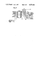
- FIG. 2 shows a further component of the system including a control latch
- the CPU 20 has an associated bus but this bus includes 16 data lines and 23 address lines.
- this bus includes 16 data lines and 23 address lines.
- the memory 12 preferably has a capacity of 64K.
- This memory 22 may have a capacity of 128K or 256K. Both of the memories 12 and 22, as discussed in further detail hereinafter, are connected so that the CPU 10 has access to both its own associated memory 12 and also to the memory 22 which the CPU 10 can access in 16K chunks. On the other hand the CPU 20 has access only to its own associated memory 22.
- this processor is of conventional design identified previously as a Motorola type MC68000 having 16-bit operation for high level language tasks.
- the processor supports direct access for up to 7 megabytes of memory, supports 8 levels of vectored interrupts, has 4 levels of fixed priority bus arbitration and also has a memory interface controller for interfacing with the processor 10.
- FIG. 1 the CPU 20 is shown in block form, it is understood that this comprises a central processing unit and also an interrupt controller which may be of type AM9519A.
- the CPU 10, as mentioned previously, may be an Intel type Z80.
- the Z80 processor 10 includes a Z80-A CPU (central processing unit), a Z80-A CTC (counter timer chip), a Z80-A DMA (direct memory access), and a Z80-A SIO (serial input/out). These different components are interconnected in a conventional manner enabling operation of the Z80 processor for use essentially as an I/O controller, at least for 16-bit operation.
- boot ROM 14 As indicated in FIG. 1, there is associated with the processor 10, a boot ROM 14. The details of operation in connection with boot ROM operation are described hereinafter.
- the processor 10 provides boot-strap firmware which resides in the lower 2K of the 64K address space. The boot-strap firmware is switched out of the address space after boot-up is complete.
- the aforementioned boot ROM 14 may be implemented by means of an erasable or non-erasable programmable read-only memory.
- the ROM 14 may be of type 2716 or type 2316. There are typically 8 data lines and 11 address lines along with enabling lines associated with this boot ROM.
- the Z80 processor 10 When the system depicted in FIG. 1 is in operation as a 16 bit machine, the Z80 processor 10 functions as an I/O processor. Thus, it receives signals from the outside world over the I/O bus depicted in FIG. 1 and this information is transferred into the Z80 memory 12 which as mentioned previously, is a 64K capacity memory. Information in the memory 12 may then be formatted and transferred at high speed over internally connecting buses into the memory 22 where the data can be used by the processor 20.
- the additional transfer devices depicted in FIG. 1 including an upper data buffer 30, a lower data buffer 32, a latch 34, and a data buffer 36. The operation of these devices is described in more detail hereinafter.
- FIG. 1 diagrammatically illustrates this mailbox location or field 24.
- FIG. 1 diagrammatically illustrates this mailbox location or field 24.
- the CPU 20 In order to transmit data to the I/O bus, the CPU 20 first stores data in its own memory 22 and places a special transfer command in the mailbox location 24. The CPU 20 then initiates an interrupt signal by activating one of the interrupt lines coupling to the processor 10 causing the processor 10 to branch to an interrupt program. This interrupt program causes the processor 10 to examine the mailbox location 24 in the memory 22 and retrieve the command that is stored therein. This command then causes the processor 10 to transfer the information out of the memory 22 via the internal data buses to its own memory 12. Now that the processor 10 has been able to transfer the information to its own memory, from there the information can be formatted and sent out from the processor 10 to the I/O bus.
- the processor 10 is provided with access to the other processor's memory, namely memory 22.
- the access to the memory 22 is by way of address lines from the processor 10.
- the address bus associated with the processor 10 has 16 address lines.
- addresses A0-A14 are shown coupling from the address bus to the address generator control buffer 36.
- This buffer may be a circuit chip of type LS 244 with two such LS 244 devices being used to provide the entire buffer.
- the output from the buffer 36 is shown as a single line but actually comprises a plurality of lines identified as address lines BA1-BA14.
- the buffer 36 is indicated in FIG.
- FIG. 1 is an interconnecting link between the address bus of the processor 10 and the address bus of the processor 20.
- the control of address data through the buffer 36 is unidirectional.
- One other output taken from the buffer 36 is indicated in FIG. 1 as connecting to a bus arbitration chip.
- the bus arbitration circuitry is not described in detail herein, as it is considered to be of a conventional nature including a bus arbitration control chip of type 16R6.
- the bus arbitration operation allows other devices capable of being bus master to request, be granted, and acknowledge bus mastership. In fact, a bus request signal is used to enable data transfer through the buffer 36.
- FIG. 3 shows a programmable logic array device 40.
- This device may be of type HAL 16R6.
- FIG. 3 note the connection of the signal A0 at the input pin 6, input I6.
- This address signal is used to indicate to the device 40 whether an even or odd address is being generated.
- FIG. 3 also shows, in addition to the device 40, a gate 42 and a series of enableable drivers all of which are identified by the designation 44. It is noted that all of the drivers are enabled by a bus grant signal identified in FIG. 3 as a signal BG1.
- the input at pin 1 to the device 40 shown in FIG. 3 is a 8MHz signal which is at twice the clock frequency of the Z80 CPU 10.
- the input signal at the pin 2 to the device 40 is at half that frequency of 8MHz. This is the direct clock frequency associated with the Z80 processor.
- Pin 3 at the corresponding input I3 is the signal ADDVAL which is a signal indicating a valid address or actually a valid range of the addresses that are to be interpreted by the main CPU 20.
- the signals at the input pins 4 and 5 are respective READ and WRITE signals from the Z80 processor 10. Discussion has been made previously with respect to the inputted pin 6, this being the signal AO.
- the input at pin 7 which is input I7 to the device 40 is the signal BGl which is the bus grant signal generated from the BUS arbitration control circuitry. The function of this signal is discussed in further detail hereinafter.
- the signal at the input pin 8 which is the signal BDTACK is a signal that goes low and is a reply from the memory that the address is valid.
- the input at pin 9 which is the memory select signal coupled from the gate 42.
- One of the inputs to the gate 42 is a memory request signal from the Z80 processor along with a second signal which functions as a master enable signal for the device 40.
- the enable input is tied to ground at pin 11.
- Pin 12 is the signal CONTO. This is a control output which allows one to redefine what is even or odd as far as the address you are reading from or writing to.
- the signal BLDS At pin 11 which is the output Q1 there is generated by way of a driver 44 the signal BLDS. Along with this signal there is also the signal BUDS which is generated from the Q2 output at pin 14. These signals are respectively the bus lower and upper data strobes. These signals are used in association with the CPU 20 and in particular its memory for the transfer of data thereto and the reading of data therefrom.
- the enabling bus grant signal that couples to the respective driver 44.
- the signal BAS that is generated initiates the cycle of the CPU 20.
- the next output from the device 40 is at pin 16 and is the signal BR1 which is the bus request signal.
- this signal goes low it indicates to the bus arbitration circuit that someone is requesting access to the CPU bus. In other words this signal tells the CPU 20 that someone wants access to its bus.
- the bus grant request signal BUSGQ is a signal that is essentially the same as the signal BG1 but delayed by one clock cycle.
- the signal WAIT which couples back to the Z80 processor and suspends or freezes the Z80 processor information until the bus grant becomes valid.
- the address control is essentially initiated by the signal CONTI which signals the device 40 to look at the inputs to see if they are valid and to see if they initiate transfers to or from the memory of the CPU 20 once this signal is activated.
- the device 40 is looking for the Z80 bus cycle in the correct address range.
- the WAIT signal is generated which indicates that the CPU is not quite ready for operation.
- the bus request signal is then sent to the bus arbitration circuit and a waiting period may occur while the CPU 20 is finishing a processing cycle. Thereafter, a bus grant is executed with the signal BG1 going low. This signal then enables the drivers 44 to initiate READ and WRITE cycles for memory control. Thereafter, the WAIT signal is released permitting the Z80 processor to transfer data under READ and WRITE control to or from the CPU 20 memory.
- a latch device 34 This provides an additional 8 bits of address signal provided from the processor 10 over its 8 data output lines. In FIG. 1 these lines are defined as data signals D0-D7 totaling 8 bits. These data signals, used as address signals are latched in the latch 34 and provided to the address bus associated with the processor 20. These addresses are indicated on the processor 20 side of the latch as processor 20 addresses BA15-BA22. Thus, the processor 10 provides a total of 22 address signals to the address bus of the processor 20.
- the processor 10 is adapted to access a portion of the memory space of memory 22.
- the processor 10 preferably accesses a 16K page at a time.
- the processor 10 first selects the page by putting the address signals on its bus into a latch, which in the embodiment of FIG. 1 is the latch 34. Actually, these address signals are generated on the data bus of the processor 10. The locations on each page are then addressed by manipulating the lower 14 address bits by way of the buffer 36.
- FIG. 1 This data transfer is illustrated in FIG. 1 by means of the data buffers 30 and 32, more particularly referred to as an upper data buffer 30 and a lower data buffer 32. It is noted that these buffers interconnect the data buses of the respective processors 10 and 20.
- the 8-bits of data on the data bus couple in common to each of the data buffers.
- the 16-bits are coupled to the 16-bit data bus, identified in FIG. 1 as the data signals BD0-BD15.
- the latch 34 may be comprised of two separate latch devices, each of type LS244.
- a bus request signal (not shown) is used to enable these buffers.
- the latch 34 functions as an address generator interconnected between the processor buses. This may be a latch of type MC3482B and may also be controlled by a bus grant signal.
- the data buffers 30 and 32 these may each be of type LS245. These data buffers are bi-directional and include enabling circuits for providing proper timing in the transfer of data.
- a latch 26 shown in FIG. 2 which connects to the data bus of the processor 10 and has its outputs used as control for the CPU 20.
- the latch 26 shown in FIG. 2 may be referred to as a control latch which allows the processor 10 to halt or reset the processor 20 to enable the boot-up operation to be described hereinafter.
- the latch 26 may be of type MC3482A. It is noted that its inputs couple from the data bus of the processor 10.
- the outputs include a halt output, a reset output and a plurality of interrupt outputs referred to as CONT 0, CONT 4, CONT 5, and CONT 6.
- Communication between the two processors is accomplished with the processor 10 initiating interrupts to the processor 20, and also indicating I/0 completion.
- the processor 10 may periodically poll the memory 22 of the processor 12 to recognize requests for service from the processor 20.
- the processor 20 can generate an interrupt to the processor 10 by accessing a decoded memory 22 location.
- a descriptor block is read into the memory 12 from the memory 22 to determine the specific service required.
- all memory 12 pages are deselected by resetting the lower nibble of port OFFH.
- the stack and control program is located in the lower 32K of the processor 10 address space, since page 0 is not to be disabled.
- the memory 22 shown in FIG. 1, is a random access memory with a total capacity of 128K words (256K bytes) of data with optional byte parity for error detection. It is for use with the processor 20.
- the processor 20 has a 16-bit wide data bus as indicated previously, and therefore, the memory 22 also has a 16-bit wide data bus connected thereto.
- the memory 22 is further divided into upper and lower bytes with each byte being 8-bits. Actually, all transfers to and from the memory 22 are treated as byte transfers. If a full 16-bit transfer is desired, an upper and lower byte transaction is performed simultaneously. Thus, the memory is organized as two parallel byte memories which share a common memory space. There are also means provided for parity checking. However, because the parity checking does not effect the concepts of the invention, it is not described in any detail herein.
- both memories 12 and 22 shown in FIG. 1 is substantially conventional.
- this is a memory having a data capacity of 64K.
- this is a dynamic random access memory comprising a series of integrated circuity chips each containing 65,536 (64K) single bit locations. Therefore, to store each byte with parity, 9 integrated circuits are required.
- Each chip may be of type MCM 6665.
- Address line A0 internal to the CPU 20, is used to distinguish between upper and lower bytes. Then, bits A1-A16 identify the remainder of the address. Therefore, the address lines are loaded into memory in two parts:
- Row address (A1-A8), first by the Row Address Strobe (RAS).
- the memory alters or presents the data at that location, depending on the state of the read/write signal. Refresh is required to maintain the information stored in the memory. In this connection every two milliseconds, the entire contents of the memory are refreshed. Due to the memory structure, this requires 128 refresh only accesses every two milliseconds, or one every 16.0 microseconds.
- FIG. 1 only schematically shows the memory 22, it is understood that in addition to memory storage space, there is also control associated with the memory.
- the address lines BA1-BA16 are routed to the memory through two-line, receiver-inverting buffers which are permanently enabled. These buffers may be of type 74S240.
- the lower 8 address lines, namely lines BA1-BA8 are multiplexed with 8 refresh address bits from the refresh address counter (not shown) thus becoming the 8 memory row address bits.
- the row address bits are then multiplexed with the column address bits which are address lines BA9-BA16, thus becoming the 8 multiplexed address bits.
- the memory address lines are routed to all memory chips through series resistors to reduce ringing and overshoot.
- the address line BA17 is routed to the memory and enables gating to generate the signal RAS for the lower or upper 120K memory page.
- Address lines BA18-BA22 are used to enable the memory at a specific 256K location within the processor 20 sub-system memory map allocation.
- the memory 22 is accessed by 16 bits of information with the remaining bits being used to determine the location of the 256K memory in the address bit. That is, the processor 20 has 23 address bits which are equivalent to about 16 megabytes.
- the remaining 8-bits are put into a comparator which is an 8-bit magnitude comparator such as type LS688. This comparator compares two 8-bit inputs. Address lines are compared with a preset value by the use of a dip switch. If the signals match, then the memory is enabled and if they don't match then it is not enabled.
- the memory chips that are used in the memory 22 are addressed by means of a multiplex arrangement. That is, 8 address signals are provided to the chips and the lower 8-bits of the address are first placed on the 8 leads and strobed into the memory chips by means of a Row Address Strobe (RAS) signal. Then, the lower 8-bit signals are removed, the upper 8-bit signals are placed on the line and strobed into the memory by a Column Address Strobe (CAS) signal.
- RAS Row Address Strobe
- CAS Column Address Strobe
- this boot ROM may be of type 2716 or of type 2316.
- Type 2716 is an erasable programmable ROM while type 2316 is a masked ROM.
- This boot ROM 14 has 8 data lines and 11 address lines along with enable signals therefor.
- the boot ROM loads a boot strap program into the memory 12 associated with processor 10. This boot program then loads the software for both processors which determines that the processor 12 is the main processor while the processor 10 functions as an I/O processor.
- the boot ROM 14 when the computer system is initially started up, there is a register in the processor 10 which causes the boot ROM 14 to be interpreted as the lower 2K of memory. Thus, the boot ROM 14 in a sense replaces a portion of the memory 12 during this power-up phase.
- a reset signal that is generated, at the output of a circuit which is referred to as the power on and manual reset logic circuit 31.
- the reset signal to the processor 10 causes it to go to location 0 and extract the instruction therein and execute it.
- This instruction is the first instruction in a boot program and thus at power-up the processor 10 simply looks at the boot ROM 14 first instruction in a boot-up program which causes the processor 10 to access specified tracks and sectors in an attached diskette 28 so as to load in the operating system from the diskette into the 64K memory 12 associated with the processor 10.
- the operating system from the diskette is stored in the memory 12 at a location starting directly above the lower 2K of memory, namely at location 2001.
- the processor 10 is adapted to interpret the first memory spaces as from the ROM 14 rather than from the memory 12. This has the effect of causing the processor 10 to transfer the operating program from the diskette 28 into the memory 12 but starting at memory location 2001.
- the boot ROM 14 has an instruction which causes the processor 10 to jump to a location in the operating system which starts the operating system running. This thus completes the initialization of the system.
- the operating system begins to run, one of the first things that happens is that it shuts the aforementioned register in the processor 10 which had caused the processor to access the boot ROM by accessing the lower 2K of memory.
- the operating system instead, once it begins to run, causes the processor 10 to access the 64K memory 12 rather than the boot ROM.
- the boot ROM 14 is taken out of the system and no longer has any effect until the system is again reset.
- the system of the present invention although termed a second generation system is usable with first generation programs and operating systems and operates in this manner by simply not enabling operation of the processor 20 with all processing being done by the processor 10.
- the processor 10 thus does not act predominantly only as an I/O processor, but instead is the main processor.
- the processor 10 After the operating system for the processor 20 has been transferred from the 64K memory 12 to the memory 22, the processor 10 resets itself and at substantially the same time releases the halt on the processor 20. The processor 20 is then able to boot itself up using the program now stored in its memory 22. In this way, the processor 20 assumes control of the system and in turn now controls the processor 10 by means of the internal interrupt operation indicated by the interrupt line 26 illustrated in FIG. 1.
- interrupt outputs of the latch 26 are interrupt outputs generated from the processor 10 data bus. Thus, these are interrupts that are initiated by the processor 10.
- some of the these signals are CONT 4, CONT 5, and CONT 6.
- Their corresponding respective vector locations are 234H, 238H and 23CH.
- the interrupt control function for the system is implemented with an interrupt controller such as the type AM9519 not specifically described herein but considered to be of conventional design.
- a single unit manages up to 8 maskable interrupt request inputs, resolves priorities and supplies the vector number response to the processor 20 at interrupt acknowledge time.
- the controller receives an unmasked interrupt request, it issues a group interrupt request to the processor 20.
- the controller When the interrupt is acknowledged, the controller outputs the pre-programmed vector number corresponding to the highest priority unmasked interrupt request.
Abstract
Description
Claims (23)
Priority Applications (1)
| Application Number | Priority Date | Filing Date | Title |
|---|---|---|---|
| US06/796,760 US4679166A (en) | 1983-01-17 | 1985-11-12 | Co-processor combination |
Applications Claiming Priority (2)
| Application Number | Priority Date | Filing Date | Title |
|---|---|---|---|
| US06/458,541 US4590556A (en) | 1983-01-17 | 1983-01-17 | Co-processor combination |
| US06/796,760 US4679166A (en) | 1983-01-17 | 1985-11-12 | Co-processor combination |
Related Parent Applications (1)
| Application Number | Title | Priority Date | Filing Date |
|---|---|---|---|
| US06/458,541 Continuation US4590556A (en) | 1983-01-17 | 1983-01-17 | Co-processor combination |
Publications (1)
| Publication Number | Publication Date |
|---|---|
| US4679166A true US4679166A (en) | 1987-07-07 |
Family
ID=27039038
Family Applications (1)
| Application Number | Title | Priority Date | Filing Date |
|---|---|---|---|
| US06/796,760 Expired - Lifetime US4679166A (en) | 1983-01-17 | 1985-11-12 | Co-processor combination |
Country Status (1)
| Country | Link |
|---|---|
| US (1) | US4679166A (en) |
Cited By (61)
| Publication number | Priority date | Publication date | Assignee | Title |
|---|---|---|---|---|
| WO1988008564A1 (en) * | 1987-04-23 | 1988-11-03 | Commodore-Amiga, Inc. | A method of communicating data between the cpu of a host computer system and the cpu of a co-processor computer system |
| US4814977A (en) * | 1983-10-18 | 1989-03-21 | S&C Electric Company | Apparatus and method for direct memory to peripheral and peripheral to memory data transfers |
| US4825358A (en) * | 1985-04-10 | 1989-04-25 | Microsoft Corporation | Method and operating system for executing programs in a multi-mode microprocessor |
| US4870614A (en) * | 1984-08-02 | 1989-09-26 | Quatse Jesse T | Programmable controller ("PC") with co-processing architecture |
| US4926318A (en) * | 1986-11-12 | 1990-05-15 | Nec Corporation | Micro processor capable of being connected with a coprocessor |
| US4949241A (en) * | 1987-10-22 | 1990-08-14 | Nec Corporation | Microcomputer system including a master processor and a slave processor synchronized by three control lines |
| US4979102A (en) * | 1987-12-03 | 1990-12-18 | Nec Corporation | Microprocessor operable under direct connection to coprocessor |
| US5027272A (en) * | 1988-01-28 | 1991-06-25 | Weitek Corporation | Method and apparatus for performing double precision vector operations on a coprocessor |
| US5101490A (en) * | 1989-01-10 | 1992-03-31 | Bull Hn Information Systems Inc. | Peripheral device controller with an EEPROM with microinstructions for a RAM control store |
| US5113500A (en) * | 1989-08-23 | 1992-05-12 | Unisys Corporation | Multiple cooperating and concurrently operating processors using individually dedicated memories |
| US5113522A (en) * | 1989-05-17 | 1992-05-12 | International Business Machines Corporation | Data processing system with system resource management for itself and for an associated alien processor |
| WO1992009033A1 (en) * | 1990-11-09 | 1992-05-29 | Ast Research, Inc. | Method and apparatus for providing down-loaded instructions for execution by a peripheral controller |
| US5119499A (en) * | 1988-05-27 | 1992-06-02 | Hitachi Ltd. | Host processor which includes apparatus for performing coprocessor functions |
| US5133057A (en) * | 1988-05-25 | 1992-07-21 | Nec Corporation | Co-processor for control setting an internal flag register operation mode which controlled a main processor execution mode in a multi-processor system |
| US5142680A (en) * | 1989-04-26 | 1992-08-25 | Sun Microsystems, Inc. | Method for loading an operating system through a network |
| US5144692A (en) * | 1989-05-17 | 1992-09-01 | International Business Machines Corporation | System for controlling access by first system to portion of main memory dedicated exclusively to second system to facilitate input/output processing via first system |
| US5155809A (en) * | 1989-05-17 | 1992-10-13 | International Business Machines Corp. | Uncoupling a central processing unit from its associated hardware for interaction with data handling apparatus alien to the operating system controlling said unit and hardware |
| US5155833A (en) * | 1987-05-11 | 1992-10-13 | At&T Bell Laboratories | Multi-purpose cache memory selectively addressable either as a boot memory or as a cache memory |
| US5168562A (en) * | 1989-02-21 | 1992-12-01 | Compaq Computer Corporation | Method and apparatus for determining the allowable data path width of a device in a computer system to avoid interference with other devices |
| WO1993000628A1 (en) * | 1991-06-26 | 1993-01-07 | Ast Research, Inc. | Multiprocessor distributed initialization and self-test system |
| US5179691A (en) * | 1989-04-12 | 1993-01-12 | Unisys Corporation | N-byte stack-oriented CPU using a byte-selecting control for enhancing a dual-operation with an M-byte instruction word user program where M<N<2M |
| US5193174A (en) * | 1990-07-23 | 1993-03-09 | International Business Machines Corporation | System for automatically redirecting information to alternate system console in response to the comparison of present and default system configuration in personal computer system |
| US5230065A (en) * | 1987-12-21 | 1993-07-20 | Bull Hn Information Systems Inc. | Apparatus and method for a data processing system having a peer relationship among a plurality of central processing units |
| US5237676A (en) * | 1989-01-13 | 1993-08-17 | International Business Machines Corp. | High speed data transfer system which adjusts data transfer speed in response to indicated transfer speed capability of connected device |
| US5283868A (en) * | 1989-05-17 | 1994-02-01 | International Business Machines Corp. | Providing additional system characteristics to a data processing system through operations of an application program, transparently to the operating system |
| US5325517A (en) * | 1989-05-17 | 1994-06-28 | International Business Machines Corporation | Fault tolerant data processing system |
| US5329631A (en) * | 1989-03-16 | 1994-07-12 | Fujitsu Limited | Microprocessor system for effectively using a part of an address space |
| US5369767A (en) * | 1989-05-17 | 1994-11-29 | International Business Machines Corp. | Servicing interrupt requests in a data processing system without using the services of an operating system |
| US5369749A (en) * | 1989-05-17 | 1994-11-29 | Ibm Corporation | Method and apparatus for the direct transfer of information between application programs running on distinct processors without utilizing the services of one or both operating systems |
| US5408664A (en) * | 1992-06-19 | 1995-04-18 | Silicon Graphics, Incorporated | System and Method for booting computer for operation in either of two byte-order modes |
| US5410707A (en) * | 1991-04-29 | 1995-04-25 | Intel Corporation | Bootstrap loading from external memory including disabling a reset from a keyboard controller while an operating system load signal is active |
| US5465360A (en) * | 1989-11-03 | 1995-11-07 | Compaq Computer Corp. | Method and apparatus for independently resetting processors and cache controllers in multiple processor systems |
| US5467453A (en) * | 1993-07-20 | 1995-11-14 | Dell Usa, L.P. | Circuit for providing automatic SCSI bus termination |
| US5577257A (en) * | 1987-08-27 | 1996-11-19 | Canon Kabushiki Kaisha | Information processing apparatus |
| US5590363A (en) * | 1989-04-18 | 1996-12-31 | Dell Usa, L.P. | Circuit for detection of co-processor unit presence and for correction of its absence |
| US5642110A (en) * | 1990-11-09 | 1997-06-24 | Ast Research, Inc. | Memory mapped keyboard controller |
| US5655106A (en) * | 1991-06-10 | 1997-08-05 | International Business Machines Corporation | Personal computer with riser connector for expansion bus and alternate master |
| WO1997029451A1 (en) * | 1996-02-09 | 1997-08-14 | Iomega Corporation | Methods and apparatus for booting a computer having a removable media disk drive |
| US5680632A (en) * | 1992-12-24 | 1997-10-21 | Motorola, Inc. | Method for providing an extensible register in the first and second data processing systems |
| US5799204A (en) * | 1995-05-01 | 1998-08-25 | Intergraph Corporation | System utilizing BIOS-compatible high performance video controller being default controller at boot-up and capable of switching to another graphics controller after boot-up |
| US5835784A (en) * | 1995-06-15 | 1998-11-10 | Intel Corporation | System for booting processor from remote memory by preventing host processor from configuring an environment of processor while configuring an interface unit between processor and remote memory |
| US5870602A (en) * | 1987-11-03 | 1999-02-09 | Compaq Computer Corporation | Multi-processor system with system wide reset and partial system reset capabilities |
| US5949997A (en) * | 1997-01-03 | 1999-09-07 | Ncr Corporation | Method and apparatus for programming a microprocessor using an address decode circuit |
| US6058475A (en) * | 1997-09-22 | 2000-05-02 | Ncr Corporation | Booting method for multi-processor computer |
| US6154837A (en) * | 1998-02-02 | 2000-11-28 | Mitsubishi Denki Kabushiki Kaisha | Microcomputer enabling an erase/write program of a flash memory to interrupt by transferring interrupt vectors from a boot ROM to a RAM |
| WO2002001345A2 (en) * | 2000-06-29 | 2002-01-03 | Telecom Italia Lab S.P.A. | Method and apparatus for arbitration of concurrent processes in multiprocessor systems |
| US6400717B1 (en) | 1998-10-16 | 2002-06-04 | Samsung Electronics Co., Ltd. | Device for booting a multiprocessor embedded system and method of operation |
| US6463529B1 (en) | 1989-11-03 | 2002-10-08 | Compaq Computer Corporation, Inc. | Processor based system with system wide reset and partial system reset capabilities |
| EP1271307A1 (en) * | 2000-03-03 | 2003-01-02 | Sony Computer Entertainment Inc. | Compatible entertainment device and computer system |
| US6772241B1 (en) | 2000-09-29 | 2004-08-03 | Intel Corporation | Selective interrupt delivery to multiple processors having independent operating systems |
| US6931474B1 (en) | 1999-09-23 | 2005-08-16 | Intel Corporation | Dual-function computing system having instant-on mode of operation |
| US6937722B2 (en) * | 2001-02-26 | 2005-08-30 | Oki Electric Industry Co., Ltd. | Method and apparatus for echo cancellation |
| US20060026417A1 (en) * | 2004-07-30 | 2006-02-02 | Information Assurance Systems L.L.C. | High-assurance secure boot content protection |
| US20060069904A1 (en) * | 2004-09-30 | 2006-03-30 | Tetsuo Hatakeyama | Information processing apparatus and startup control method |
| US7098899B1 (en) * | 1999-09-21 | 2006-08-29 | Intel Corporation | Dual form low power, instant on and high performance, non-instant on computing device |
| US20070012758A1 (en) * | 2005-07-14 | 2007-01-18 | Wilson Wanda J | Device and method for recording financial information |
| US20070088932A1 (en) * | 2001-10-24 | 2007-04-19 | Cray Inc. | System and method for addressing memory and transferring data |
| US20090024883A1 (en) * | 2007-07-19 | 2009-01-22 | Bethard Roger A | Inter-asic data transport using link control block manager |
| US8572404B2 (en) * | 2011-11-04 | 2013-10-29 | Honeywell International Inc. | Security and safety manager implementation in a multi-core processor |
| US8667123B2 (en) | 2008-09-29 | 2014-03-04 | Woodhead Industries, Inc. | Microcontroller network diagnostic system |
| US20160283721A1 (en) * | 2012-06-28 | 2016-09-29 | Intel Corporation | Out-of-band host os boot sequence verification |
Citations (8)
| Publication number | Priority date | Publication date | Assignee | Title |
|---|---|---|---|---|
| US3786433A (en) * | 1971-09-29 | 1974-01-15 | Kent Ltd G | Computer control arrangements |
| DE2538895A1 (en) * | 1974-09-06 | 1976-03-18 | Data Recall Ltd | PROGRAMMABLE DATA PROCESSING SYSTEM |
| FR2349880A1 (en) * | 1976-04-29 | 1977-11-25 | Ncr Co | DATA PROCESSING SYSTEM |
| US4070704A (en) * | 1976-05-17 | 1978-01-24 | Honeywell Information Systems Inc. | Automatic reconfiguration apparatus for input/output processor |
| US4412286A (en) * | 1980-09-25 | 1983-10-25 | Dowd Brendan O | Tightly coupled multiple instruction multiple data computer system |
| US4430710A (en) * | 1981-08-24 | 1984-02-07 | Burroughs Corporation | Subsystem controller |
| US4471427A (en) * | 1981-12-01 | 1984-09-11 | Burroughs Corporation | Direct memory access logic system for a data transfer network |
| US4481578A (en) * | 1982-05-21 | 1984-11-06 | Pitney Bowes Inc. | Direct memory access data transfer system for use with plural processors |
-
1985
- 1985-11-12 US US06/796,760 patent/US4679166A/en not_active Expired - Lifetime
Patent Citations (8)
| Publication number | Priority date | Publication date | Assignee | Title |
|---|---|---|---|---|
| US3786433A (en) * | 1971-09-29 | 1974-01-15 | Kent Ltd G | Computer control arrangements |
| DE2538895A1 (en) * | 1974-09-06 | 1976-03-18 | Data Recall Ltd | PROGRAMMABLE DATA PROCESSING SYSTEM |
| FR2349880A1 (en) * | 1976-04-29 | 1977-11-25 | Ncr Co | DATA PROCESSING SYSTEM |
| US4070704A (en) * | 1976-05-17 | 1978-01-24 | Honeywell Information Systems Inc. | Automatic reconfiguration apparatus for input/output processor |
| US4412286A (en) * | 1980-09-25 | 1983-10-25 | Dowd Brendan O | Tightly coupled multiple instruction multiple data computer system |
| US4430710A (en) * | 1981-08-24 | 1984-02-07 | Burroughs Corporation | Subsystem controller |
| US4471427A (en) * | 1981-12-01 | 1984-09-11 | Burroughs Corporation | Direct memory access logic system for a data transfer network |
| US4481578A (en) * | 1982-05-21 | 1984-11-06 | Pitney Bowes Inc. | Direct memory access data transfer system for use with plural processors |
Non-Patent Citations (4)
| Title |
|---|
| Barthmaier, "Multiprocessing System Mixes 8- and 16-Bit Microcomputers", Computer Design, vol. 19, No. 2, Feb. 1980, pp. 137-144. |
| Barthmaier, Multiprocessing System Mixes 8 and 16 Bit Microcomputers , Computer Design, vol. 19, No. 2, Feb. 1980, pp. 137 144. * |
| Folsom et al., "Paired Processors Boost Micro's Performance", Computer Design, vol. 21, No. 11, Nov. 1982, pp. 101-106. |
| Folsom et al., Paired Processors Boost Micro s Performance , Computer Design, vol. 21, No. 11, Nov. 1982, pp. 101 106. * |
Cited By (81)
| Publication number | Priority date | Publication date | Assignee | Title |
|---|---|---|---|---|
| US4814977A (en) * | 1983-10-18 | 1989-03-21 | S&C Electric Company | Apparatus and method for direct memory to peripheral and peripheral to memory data transfers |
| US4870614A (en) * | 1984-08-02 | 1989-09-26 | Quatse Jesse T | Programmable controller ("PC") with co-processing architecture |
| US4825358A (en) * | 1985-04-10 | 1989-04-25 | Microsoft Corporation | Method and operating system for executing programs in a multi-mode microprocessor |
| US4926318A (en) * | 1986-11-12 | 1990-05-15 | Nec Corporation | Micro processor capable of being connected with a coprocessor |
| WO1988008564A1 (en) * | 1987-04-23 | 1988-11-03 | Commodore-Amiga, Inc. | A method of communicating data between the cpu of a host computer system and the cpu of a co-processor computer system |
| US5155833A (en) * | 1987-05-11 | 1992-10-13 | At&T Bell Laboratories | Multi-purpose cache memory selectively addressable either as a boot memory or as a cache memory |
| US5577257A (en) * | 1987-08-27 | 1996-11-19 | Canon Kabushiki Kaisha | Information processing apparatus |
| US4949241A (en) * | 1987-10-22 | 1990-08-14 | Nec Corporation | Microcomputer system including a master processor and a slave processor synchronized by three control lines |
| US5870602A (en) * | 1987-11-03 | 1999-02-09 | Compaq Computer Corporation | Multi-processor system with system wide reset and partial system reset capabilities |
| US4979102A (en) * | 1987-12-03 | 1990-12-18 | Nec Corporation | Microprocessor operable under direct connection to coprocessor |
| US5230065A (en) * | 1987-12-21 | 1993-07-20 | Bull Hn Information Systems Inc. | Apparatus and method for a data processing system having a peer relationship among a plurality of central processing units |
| US5027272A (en) * | 1988-01-28 | 1991-06-25 | Weitek Corporation | Method and apparatus for performing double precision vector operations on a coprocessor |
| US5133057A (en) * | 1988-05-25 | 1992-07-21 | Nec Corporation | Co-processor for control setting an internal flag register operation mode which controlled a main processor execution mode in a multi-processor system |
| US5119499A (en) * | 1988-05-27 | 1992-06-02 | Hitachi Ltd. | Host processor which includes apparatus for performing coprocessor functions |
| US5101490A (en) * | 1989-01-10 | 1992-03-31 | Bull Hn Information Systems Inc. | Peripheral device controller with an EEPROM with microinstructions for a RAM control store |
| US5237676A (en) * | 1989-01-13 | 1993-08-17 | International Business Machines Corp. | High speed data transfer system which adjusts data transfer speed in response to indicated transfer speed capability of connected device |
| US5168562A (en) * | 1989-02-21 | 1992-12-01 | Compaq Computer Corporation | Method and apparatus for determining the allowable data path width of a device in a computer system to avoid interference with other devices |
| US5329631A (en) * | 1989-03-16 | 1994-07-12 | Fujitsu Limited | Microprocessor system for effectively using a part of an address space |
| US5179691A (en) * | 1989-04-12 | 1993-01-12 | Unisys Corporation | N-byte stack-oriented CPU using a byte-selecting control for enhancing a dual-operation with an M-byte instruction word user program where M<N<2M |
| US5590363A (en) * | 1989-04-18 | 1996-12-31 | Dell Usa, L.P. | Circuit for detection of co-processor unit presence and for correction of its absence |
| US5142680A (en) * | 1989-04-26 | 1992-08-25 | Sun Microsystems, Inc. | Method for loading an operating system through a network |
| US5369749A (en) * | 1989-05-17 | 1994-11-29 | Ibm Corporation | Method and apparatus for the direct transfer of information between application programs running on distinct processors without utilizing the services of one or both operating systems |
| US5363497A (en) * | 1989-05-17 | 1994-11-08 | Ibm Corporation | System for removing section of memory from first system and allocating to second system in a manner indiscernable to both operating systems |
| US5113522A (en) * | 1989-05-17 | 1992-05-12 | International Business Machines Corporation | Data processing system with system resource management for itself and for an associated alien processor |
| US5144692A (en) * | 1989-05-17 | 1992-09-01 | International Business Machines Corporation | System for controlling access by first system to portion of main memory dedicated exclusively to second system to facilitate input/output processing via first system |
| US5283868A (en) * | 1989-05-17 | 1994-02-01 | International Business Machines Corp. | Providing additional system characteristics to a data processing system through operations of an application program, transparently to the operating system |
| US5325517A (en) * | 1989-05-17 | 1994-06-28 | International Business Machines Corporation | Fault tolerant data processing system |
| US5701502A (en) * | 1989-05-17 | 1997-12-23 | International Business Machines Corporation | Isolating a central processing unit from the operating system controlling said unit and its associated hardware for interaction of the unit with data handling apparatus alien to the operating system |
| US5388215A (en) * | 1989-05-17 | 1995-02-07 | Ibm Corporation | Uncoupling a central processing unit from its associated hardware for interaction with data handling apparatus alien to the operating system controlling said unit and hardware |
| US5369767A (en) * | 1989-05-17 | 1994-11-29 | International Business Machines Corp. | Servicing interrupt requests in a data processing system without using the services of an operating system |
| US5155809A (en) * | 1989-05-17 | 1992-10-13 | International Business Machines Corp. | Uncoupling a central processing unit from its associated hardware for interaction with data handling apparatus alien to the operating system controlling said unit and hardware |
| US5113500A (en) * | 1989-08-23 | 1992-05-12 | Unisys Corporation | Multiple cooperating and concurrently operating processors using individually dedicated memories |
| US6463529B1 (en) | 1989-11-03 | 2002-10-08 | Compaq Computer Corporation, Inc. | Processor based system with system wide reset and partial system reset capabilities |
| US5465360A (en) * | 1989-11-03 | 1995-11-07 | Compaq Computer Corp. | Method and apparatus for independently resetting processors and cache controllers in multiple processor systems |
| US5611078A (en) * | 1989-11-03 | 1997-03-11 | Compaq Computer Corporation | Method and apparatus for independently resetting processors and cache controllers in multiple processor systems |
| US5737604A (en) * | 1989-11-03 | 1998-04-07 | Compaq Computer Corporation | Method and apparatus for independently resetting processors and cache controllers in multiple processor systems |
| US5193174A (en) * | 1990-07-23 | 1993-03-09 | International Business Machines Corporation | System for automatically redirecting information to alternate system console in response to the comparison of present and default system configuration in personal computer system |
| US5642110A (en) * | 1990-11-09 | 1997-06-24 | Ast Research, Inc. | Memory mapped keyboard controller |
| WO1992009033A1 (en) * | 1990-11-09 | 1992-05-29 | Ast Research, Inc. | Method and apparatus for providing down-loaded instructions for execution by a peripheral controller |
| US5261114A (en) * | 1990-11-09 | 1993-11-09 | Ast Research, Inc. | Method and apparatus for providing down-loaded instructions for execution by a peripheral controller |
| US5408624A (en) * | 1990-11-09 | 1995-04-18 | Ast Research, Inc. | Method and apparatus for down-loading instructions from a host computer system to a memory in a peripheral controller for execution by a core microprocessor in the peripheral controller |
| US5410707A (en) * | 1991-04-29 | 1995-04-25 | Intel Corporation | Bootstrap loading from external memory including disabling a reset from a keyboard controller while an operating system load signal is active |
| US5655106A (en) * | 1991-06-10 | 1997-08-05 | International Business Machines Corporation | Personal computer with riser connector for expansion bus and alternate master |
| WO1993000628A1 (en) * | 1991-06-26 | 1993-01-07 | Ast Research, Inc. | Multiprocessor distributed initialization and self-test system |
| US5659748A (en) * | 1991-06-26 | 1997-08-19 | Ast Research, Inc. | Booting of multiprocessor system from a boot ROM of narrower width than the system memory |
| US5450576A (en) * | 1991-06-26 | 1995-09-12 | Ast Research, Inc. | Distributed multi-processor boot system for booting each processor in sequence including watchdog timer for resetting each CPU if it fails to boot |
| US5524245A (en) * | 1992-06-19 | 1996-06-04 | Silicon Graphics, Inc. | System for booting computer for operation in either one of two byte-order modes |
| US5408664A (en) * | 1992-06-19 | 1995-04-18 | Silicon Graphics, Incorporated | System and Method for booting computer for operation in either of two byte-order modes |
| US5680632A (en) * | 1992-12-24 | 1997-10-21 | Motorola, Inc. | Method for providing an extensible register in the first and second data processing systems |
| US5467453A (en) * | 1993-07-20 | 1995-11-14 | Dell Usa, L.P. | Circuit for providing automatic SCSI bus termination |
| US5799204A (en) * | 1995-05-01 | 1998-08-25 | Intergraph Corporation | System utilizing BIOS-compatible high performance video controller being default controller at boot-up and capable of switching to another graphics controller after boot-up |
| US5835784A (en) * | 1995-06-15 | 1998-11-10 | Intel Corporation | System for booting processor from remote memory by preventing host processor from configuring an environment of processor while configuring an interface unit between processor and remote memory |
| US5694600A (en) * | 1996-02-09 | 1997-12-02 | Iomega Corporation | Methods and apparatus for booting a computer having a removable media disk drive |
| WO1997029451A1 (en) * | 1996-02-09 | 1997-08-14 | Iomega Corporation | Methods and apparatus for booting a computer having a removable media disk drive |
| US5949997A (en) * | 1997-01-03 | 1999-09-07 | Ncr Corporation | Method and apparatus for programming a microprocessor using an address decode circuit |
| US6058475A (en) * | 1997-09-22 | 2000-05-02 | Ncr Corporation | Booting method for multi-processor computer |
| US6154837A (en) * | 1998-02-02 | 2000-11-28 | Mitsubishi Denki Kabushiki Kaisha | Microcomputer enabling an erase/write program of a flash memory to interrupt by transferring interrupt vectors from a boot ROM to a RAM |
| US6400717B1 (en) | 1998-10-16 | 2002-06-04 | Samsung Electronics Co., Ltd. | Device for booting a multiprocessor embedded system and method of operation |
| US7098899B1 (en) * | 1999-09-21 | 2006-08-29 | Intel Corporation | Dual form low power, instant on and high performance, non-instant on computing device |
| US6931474B1 (en) | 1999-09-23 | 2005-08-16 | Intel Corporation | Dual-function computing system having instant-on mode of operation |
| US7096309B2 (en) | 1999-09-23 | 2006-08-22 | Intel Corporation | Computing device capable of instant-on and non-instant on modes of operation |
| EP1271307A1 (en) * | 2000-03-03 | 2003-01-02 | Sony Computer Entertainment Inc. | Compatible entertainment device and computer system |
| EP1271307A4 (en) * | 2000-03-03 | 2007-07-25 | Sony Computer Entertainment Inc | Compatible entertainment device and computer system |
| WO2002001345A3 (en) * | 2000-06-29 | 2003-03-06 | Telecom Italia Lab Spa | Method and apparatus for arbitration of concurrent processes in multiprocessor systems |
| WO2002001345A2 (en) * | 2000-06-29 | 2002-01-03 | Telecom Italia Lab S.P.A. | Method and apparatus for arbitration of concurrent processes in multiprocessor systems |
| US6976099B2 (en) | 2000-09-29 | 2005-12-13 | Intel Corporation | Selective interrupt delivery to multiple processors having independent operating systems |
| US6772241B1 (en) | 2000-09-29 | 2004-08-03 | Intel Corporation | Selective interrupt delivery to multiple processors having independent operating systems |
| US6937722B2 (en) * | 2001-02-26 | 2005-08-30 | Oki Electric Industry Co., Ltd. | Method and apparatus for echo cancellation |
| US7890673B2 (en) * | 2001-10-24 | 2011-02-15 | Cray Inc. | System and method for accessing non processor-addressable memory |
| US20070088932A1 (en) * | 2001-10-24 | 2007-04-19 | Cray Inc. | System and method for addressing memory and transferring data |
| US20060026417A1 (en) * | 2004-07-30 | 2006-02-02 | Information Assurance Systems L.L.C. | High-assurance secure boot content protection |
| US8458801B2 (en) | 2004-07-30 | 2013-06-04 | Safenet, Inc. | High-assurance secure boot content protection |
| US20060069904A1 (en) * | 2004-09-30 | 2006-03-30 | Tetsuo Hatakeyama | Information processing apparatus and startup control method |
| WO2007009098A2 (en) * | 2005-07-14 | 2007-01-18 | Wilson Wanda J | Device and method for recording financial information |
| WO2007009098A3 (en) * | 2005-07-14 | 2008-02-14 | Wanda J Wilson | Device and method for recording financial information |
| US20070012758A1 (en) * | 2005-07-14 | 2007-01-18 | Wilson Wanda J | Device and method for recording financial information |
| US20090024883A1 (en) * | 2007-07-19 | 2009-01-22 | Bethard Roger A | Inter-asic data transport using link control block manager |
| US8051338B2 (en) | 2007-07-19 | 2011-11-01 | Cray Inc. | Inter-asic data transport using link control block manager |
| US8667123B2 (en) | 2008-09-29 | 2014-03-04 | Woodhead Industries, Inc. | Microcontroller network diagnostic system |
| US8572404B2 (en) * | 2011-11-04 | 2013-10-29 | Honeywell International Inc. | Security and safety manager implementation in a multi-core processor |
| US20160283721A1 (en) * | 2012-06-28 | 2016-09-29 | Intel Corporation | Out-of-band host os boot sequence verification |
Similar Documents
| Publication | Publication Date | Title |
|---|---|---|
| US4679166A (en) | Co-processor combination | |
| US4590556A (en) | Co-processor combination | |
| US5155833A (en) | Multi-purpose cache memory selectively addressable either as a boot memory or as a cache memory | |
| US4028675A (en) | Method and apparatus for refreshing semiconductor memories in multi-port and multi-module memory system | |
| US5455916A (en) | Method for performing inter-unit data transfer operations among a plurality of input/output bus interface units coupled to a common asynchronous bus | |
| US5685005A (en) | Digital signal processor configured for multiprocessing | |
| US5619720A (en) | Digital signal processor having link ports for point-to-point communication | |
| US4815034A (en) | Dynamic memory address system for I/O devices | |
| US3996564A (en) | Input/output port control | |
| US5634076A (en) | DMA controller responsive to transition of a request signal between first state and second state and maintaining of second state for controlling data transfer | |
| US5274795A (en) | Peripheral I/O bus and programmable bus interface for computer data acquisition | |
| JPS6338794B2 (en) | ||
| EP0205943B1 (en) | Composite data-processing system using multiple standalone processing systems | |
| US5199106A (en) | Input output interface controller connecting a synchronous bus to an asynchronous bus and methods for performing operations on the bus | |
| US4400772A (en) | Method and apparatus for direct memory access in a data processing system | |
| US7058779B1 (en) | Computer system initialization via boot code stored in a non-volatile memory having an interface compatible with synchronous dynamic random access memory | |
| JPH05257657A (en) | Power-on time sequence device | |
| US4344130A (en) | Apparatus to execute DMA transfer between computing devices using a block move instruction | |
| JP2000242612A (en) | System sharing memory and bus | |
| US7310717B2 (en) | Data transfer control unit with selectable transfer unit size | |
| US5414815A (en) | Method and apparatus for transferring data directly between a memory device and a peripheral device in a single address cycle under the control of a processor | |
| US4814977A (en) | Apparatus and method for direct memory to peripheral and peripheral to memory data transfers | |
| US5408666A (en) | Method and apparatus for loading a program into a program memory from a mailbox or an external ROM | |
| JPH0227696B2 (en) | JOHOSHORISOCHI | |
| US5829043A (en) | Coupler circuit and its use in a card and process |
Legal Events
| Date | Code | Title | Description |
|---|---|---|---|
| FEPP | Fee payment procedure |
Free format text: PAYOR NUMBER ASSIGNED (ORIGINAL EVENT CODE: ASPN); ENTITY STATUS OF PATENT OWNER: LARGE ENTITY |
|
| STCF | Information on status: patent grant |
Free format text: PATENTED CASE |
|
| FPAY | Fee payment |
Year of fee payment: 4 |
|
| FEPP | Fee payment procedure |
Free format text: PAYER NUMBER DE-ASSIGNED (ORIGINAL EVENT CODE: RMPN); ENTITY STATUS OF PATENT OWNER: LARGE ENTITY Free format text: PAYOR NUMBER ASSIGNED (ORIGINAL EVENT CODE: ASPN); ENTITY STATUS OF PATENT OWNER: LARGE ENTITY |
|
| AS | Assignment |
Owner name: AST RESEARCH, INC., CALIFORNIA Free format text: ASSIGNMENT OF ASSIGNORS INTEREST;ASSIGNOR:TANDY CORPORATION AND ITS RADIO SHACK DIVISION;REEL/FRAME:006847/0109 Effective date: 19940103 |
|
| FPAY | Fee payment |
Year of fee payment: 8 |
|
| AS | Assignment |
Owner name: BANK OF AMERICA NATIONAL TRUST AND SAVINGS ASSOCIA Free format text: SECURITY INTEREST;ASSIGNOR:AST RESEARCH, INC., A DELAWARE CORPORATION;REEL/FRAME:007288/0234 Effective date: 19941223 |
|
| AS | Assignment |
Owner name: AST RESEARCH, INC., CALIFORNIA Free format text: RELEASE BY SECURED PARTY;ASSIGNOR:BANK OF AMERICA NATIONAL TRUST AND SAVINGS ASSOCIATION;REEL/FRAME:007492/0165 Effective date: 19950901 |
|
| FPAY | Fee payment |
Year of fee payment: 12 |
|
| AS | Assignment |
Owner name: AST RESEARCH, INC., CALIFORNIA Free format text: SECURITY INTEREST;ASSIGNOR:AST COMPUTERS, LLC;REEL/FRAME:009703/0089 Effective date: 19990108 |
|
| AS | Assignment |
Owner name: SAMSUNG ELECTRONICS AMERICA, INC., NEW JERSEY Free format text: ASSIGNMENT OF ASSIGNORS INTEREST;ASSIGNOR:ARI SERVICE, INC.;REEL/FRAME:012665/0878 Effective date: 20020318 Owner name: ARI SERVICE, INC., CALIFORNIA Free format text: AGREEMENT OF MERGER AST RESEARCH, INC., WITH AND INTO ARI SERVICE, INC.;ASSIGNORS:AST RESEARCH, INC., A DELAWARE CORPORATION;ARI SERVICE, INC., A CALIFORNIA CORPORATION;REEL/FRAME:012691/0384 Effective date: 20000330 |
|
| AS | Assignment |
Owner name: SAMSUNG ELECTRONICS CO., LTD., KOREA, REPUBLIC OF Free format text: ASSIGNMENT OF ASSIGNORS INTEREST;ASSIGNOR:SAMSUNG ELECTRONICS AMERICA, INC.;REEL/FRAME:012721/0141 Effective date: 20020326 |
|
| AS | Assignment |
Owner name: AST COMPUTERS, LLC, CALIFORNIA Free format text: RELEASE OF SECURITY INTEREST;ASSIGNOR:ARI SERVICE, INC., AS SUCCESSOR IN INTEREST BY MERGER TO AST RESEARCH, INC.;REEL/FRAME:012852/0320 Effective date: 20020503 |
|
| FEPP | Fee payment procedure |
Free format text: PAYER NUMBER DE-ASSIGNED (ORIGINAL EVENT CODE: RMPN); ENTITY STATUS OF PATENT OWNER: LARGE ENTITY Free format text: PAYOR NUMBER ASSIGNED (ORIGINAL EVENT CODE: ASPN); ENTITY STATUS OF PATENT OWNER: LARGE ENTITY |