US4669120A - Low bit-rate speech coding with decision of a location of each exciting pulse of a train concurrently with optimum amplitudes of pulses - Google Patents
Low bit-rate speech coding with decision of a location of each exciting pulse of a train concurrently with optimum amplitudes of pulses Download PDFInfo
- Publication number
- US4669120A US4669120A US06/626,949 US62694984A US4669120A US 4669120 A US4669120 A US 4669120A US 62694984 A US62694984 A US 62694984A US 4669120 A US4669120 A US 4669120A
- Authority
- US
- United States
- Prior art keywords
- sequence
- segment
- pulses
- parameter
- excitation
- Prior art date
- Legal status (The legal status is an assumption and is not a legal conclusion. Google has not performed a legal analysis and makes no representation as to the accuracy of the status listed.)
- Expired - Lifetime
Links
Images


Classifications
-
- G—PHYSICS
- G10—MUSICAL INSTRUMENTS; ACOUSTICS
- G10L—SPEECH ANALYSIS OR SYNTHESIS; SPEECH RECOGNITION; SPEECH OR VOICE PROCESSING; SPEECH OR AUDIO CODING OR DECODING
- G10L19/00—Speech or audio signals analysis-synthesis techniques for redundancy reduction, e.g. in vocoders; Coding or decoding of speech or audio signals, using source filter models or psychoacoustic analysis
- G10L19/04—Speech or audio signals analysis-synthesis techniques for redundancy reduction, e.g. in vocoders; Coding or decoding of speech or audio signals, using source filter models or psychoacoustic analysis using predictive techniques
- G10L19/08—Determination or coding of the excitation function; Determination or coding of the long-term prediction parameters
- G10L19/10—Determination or coding of the excitation function; Determination or coding of the long-term prediction parameters the excitation function being a multipulse excitation
Definitions
- the low bit-rate speech coding method or technique is for coding an original speech signal into an output code sequence of an information transmission rate of less than 16 Kbit/sec.
- the output code sequence is either for transmission through a transmission channel or for storage in a storing medium.
- the output code sequence is decoded by a decoder where the original speech signal is reproduced by synthesis.
- the speech coding method is useful in, among others, mobile radio communication, speech synthesis, and voice mail.
- Speech coding based on a multi-pulse excitation method is proposed as a low bit-rate speech coding method in an article contributed by Bishnu S. Atal et al of Bell Laboratories to Proc. ICASSP, 1982, pages 614-617, under the title of "A New Model of LPC Excitation for Producing Natural-sounding Speech at Low Bit Rates".
- speech synthesis is carried out according to the Atal et al article by exciting a linear predictive coding (LPC) synthesizer by a sequence or train of excitation or exciting pulses.
- LPC linear predictive coding
- A-b-S analysis-by-synthesis
- the voice or speech coding system of the elder patent application is for coding a discrete speech signal sequence into an output code sequence, which is for use in exciting a synthesizing filter in a decoder.
- the discrete speech signal sequence is divisible into segments, such as frames of the discrete speech signal sequence.
- the system of the elder patent application comprises a K parameter calculator responsive to each segment of the discrete speech signal sequence for calculating a parameter sequence representative of a spectral envelope of the segment, an impulse response calculator responsive to the parameter sequence for calculating an impulse response which the synthesizing filter has for the segment, an autocorrelator responsive to the impulse response sequence for calculating an autocorrelation function of the impulse response sequence, a cross-correlator responsive to the segment and the impulse response sequence for calculating a cross-correlation function between the segment and the impulse response sequence, an excitation pulse sequence producing circuit responsive to the autocorrelation and the cross-correlation functions for producing a sequence of excitation pulses by successively deciding locations and amplitudes of the excitation pulses, a first coder for coding the parameter sequence into a parameter code sequence, a second coder for coding the excitation pulse sequence into an excitation pulse code sequence, and a multiplexer for combining the parameter code and the excitation pulse code sequences into the output
- a method of coding each segment of a discrete speech signal sequence into an output code sequence comprising the steps of: calculating a parameter sequence representative of a spectral envelope of the segment; coding the parameter sequence into a parameter code sequence; calculating an impulse response sequence of the synthesizing filter for the segment by using the parameter code sequence; calculating an autocorrelation function of the impulse response sequence; calculating a cross-correlation function between the segment and the impulse response sequence; producing a sequence of excitation pulses by using the autocorrelation and the cross-correlation functions in successively deciding locations and amplitudes of the excitation pulses with the location of a currently processed pulse of the excitation pulses decided by the use of locations and the amplitudes of previously processed pulses of the excitation pulses and with renewal of the amplitudes of the previously processed pulses carried out concurrently with decision of the amplitude of the currently processed pulse by the use of the locations of the previously and the currently processed pulses; coding
- a method of coding each segment of a discrete speech signal sequence into an output code sequence comprising the steps of: calculating a parameter sequence representative of a spectral envelope of the segment; coding the parameter sequence into a parameter code sequence; calculating an impulse response sequence of the synthesizing filter for the segment by using the parameter code sequence; calculating an autocorrelation function of the impulse response sequence; calculating a cross-correlation function between the segment and the impulse response sequence; producing a sequence of excitation pulses by using the autocorrelation and the cross-correlation functions in successively deciding locations and amplitudes of the excitation pulses with the location of a currently processed pulse of the excitation pulses and the amplitudes of previously processed pulses of the excitation pulses and of the currently processed pulse decided by the use of the locations of the previously processed pulses; coding the sequence of excitation pulses into an excitation pulse code sequence; and combining the parameter code and the excitation pulse code sequences into the output code
- FIG. 1 is a block diagram of a conventional low bit-rate speech coding device
- FIG. 2 is a block diagram of a low bit-rate speech coding device according to a first embodiment of the instant invention
- FIG. 3, drawn below FIG. 1, is a block diagram of an impulse response calculator for use in the device illustrated in FIG. 2;
- FIG. 4 is a block diagram of an autocorrelator for use in the device depicted in FIG. 2;
- FIG. 5 is a block diagram of a cross-correlator for use in the device shown in FIG. 2;
- FIG. 6 is a block diagram of a decoder for use in combination with the device illustrated in FIG. 2;
- FIG. 7 is a block diagram of an exciting pulse sequence producing circuit for use in a device which is of the type shown in FIG. 2 and is described in a prior patent application;
- FIGS. 8 (A) through (D) are diagrams for use in describing operation of the circuit depicted in FIG. 7;
- FIG. 9 is a flow chart for use in describing operation of the circuit shown in FIG. 7;
- FIG. 10 is a flow chart for use in describing operation of an exciting pulse sequence producing circuit for use in the device illustrated in FIG. 2;
- FIG. 11 is a flow chart for use in describing operation of an exciting pulse sequence producing circuit for use in a low bit-rate speech coding device according to a second embodiment of this invention.
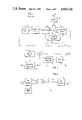
- the model comprises a linear predictive coding synthesizer 16 and an excitation pulse sequence producing circuit which is for producing a sequence of excitation pulses for use in exciting the synthesizer 16 as will be described in the following.
- a coder input terminal 17 is supplied with a discrete speech signal sequence x(n), which is produced by sampling an original speech signal at a sampling frequency of, for example, 8 KHz into speech signal samples and subjecting the samples to analog-to-digital conversion.
- a buffer memory 18 is for storing each frame of the discrete speech signal sequence x(n). The frame may be called a segment as will become clear later in the description and has a segment length of, for example, 20 milliseconds. It will be assumed that each segment consists of zeroth through (N-1)-th speech signal samples, where N is equal to one hundred and sixty under the circumstances.
- the segment is delivered from the buffer memory 18 to a K parameter calculator 19 which is for calculating a sequence of K parameters representative of a spectral envelope of the segment and for feeding the K parameter sequence to the synthesizer 16.
- the K parameters are called reflection coefficients in the Atal et al article and will herein be denoted by K m where m represents a natural number between 1 and the order M of the synthesizer 16, both inclusive.
- the order M is typically equal to sixteen.
- the K parameter sequence will be designated by the symbol K m for the K parameters.
- an excitation pulse sequence generating circuit 21 generates a sequence of excitation pulses d(n).
- the number of excitation pulses generated for each segment of the discrete speech signal sequence x(n), is equal to or less than a predetermined positive integer K, which may be eight or sixteen.
- K a predetermined positive integer
- the first through the K-th excitation pulses are not necessarily located or situated in this order along zeroth through (N-1)-th sampling instants for the zeroth through the (N-1)-th speech signal samples.
- a combination of the K parameter sequence K m and the excitation pulse sequence d(n) is delivered as an output code sequence to a coder output terminal which is not depicted in FIG. 1.
- the synthesizer 16 Supplied with the K parameter sequence K m and the excitation pulse sequence d(n), the synthesizer 16 produces a sequence of synthesized samples x(n), which are substantially identical with the respective speech signal samples. More particularly, the synthesizer 16 converts the K parameters K m into prediction parameters a m and calculates the synthesized samples x(n) in accordance with: ##EQU1##
- a substractor 22 is for subtracting the synthesized sample sequence x(n) from the discrete speech signal sequence x(n) to produce a sequence of errors e(n).
- a weighting circuit 23 is supplied with the K parameter sequence K m to weight the error sequence e(n) by weights w(n) which are dependent on the frequency characteristics of the synthesizer 16 as will shortly be described.
- the weighting circuit 23 produces a sequence of weighted errors e w (n) according to:
- the constant r be equal to unity.
- the z-transform W(z) is identically equal to unity and has a flat frequency characteristic.
- the z-transform W(z) gives an inverse of the frequency characteristics of the synthesizer 16.
- the choice of a value for the constant r is not critical. For the sampling frequency of 8 kHz, 0.8 may typically be selected for the constant r.
- the weighted error sequence e w (n) is delivered to an error minimizing circuit 24, which stores the weighted errors e w (n) for each segment and calculates the power of the stored weighted errors as an error power J.
- the error power J is given by: ##EQU3## and is fed back to the synthesizer 16.
- Locations and amplitudes of the excitation pulses d(n) are determined so as to minimize the error power J.
- the locations and the amplitudes are determined through a loop comprising a generator for the excitation pulses, calculator of the error power J, and a circuit for adjusting the locations and the amplitudes so as to minimize the error power J.
- the analysis-by-synthesis method therefore requires a large amount of calculation.
- the basic principles of a method and a device according to this invention are not much different from the principles described in the elder patent application.
- the principle of the elder patent application will be described in the following for each segment of a discrete speech signal sequence x(n).
- the segment consists of the zeroth through the (N-1)-th speech signal samples which are equally spaced along a time axis at the zeroth through the (N-1)-th sampling instants 0, . . . , n, . . . , and (N-1).
- H(z) represents the z-transform of a synthesizing filter, such as the linear predictive coding synthesizer 16 (FIG. 1), for the segment and is given by: ##EQU7## and where D(z) represents the z-transform of the excitation pulse sequence d(n).
- Equation (5) is rewritten into: ##EQU9##
- Equation (6) is therefore partially differentiated by the amplitudes g k (k being 1 through K) to provide partial derivatives.
- ⁇ hh (m i , m k ) and ⁇ xh (m k ) represent an autocorrelation or covariance function of the weighted response sequence h w (n) and a cross-correlation function between the weighted segment x w (n) and the weighted response sequence h w (n). More specifically: ##EQU11## for sampling instants m i and m j or m k between the zeroth and the (N-1)-th sampling instants, both inclusive.
- the amplitude g k of the k-th excitation pulse is regarded as a function of only the location m k of the k-th excitation pulse in Equations (7).
- the location m k is decided so as to maximize the absolute value
- the amplitude g k is determined by the maximum of the absolute values. It is therefore convenient to rewrite Equations (7) into: ##EQU12##
- a low bit-rate speech coding device is similar in structure to the system revealed in the elder patent application.
- the parts corresponding to those illustrated above in conjunction with FIG. 1 will be designated by like reference numerals.
- the device has a coder input terminal 17 supplied with a discrete speech signal sequence x(n) of the type thus far described.
- a buffer memory 18 is for storing each segment of the discrete speech signal sequence x(n).
- a K parameter calculator 19 calculates a sequence of K parameters K m representative of the spectral envelope of the segment as before. It is possible to calculate the K parameter sequence K m in the manner described in an article which is contributed by J. Makhoul to Proc. IEEE, April 1975, pages 561 to 580, under the title of "Linear Prediction: A tutorial Review".
- the K parameter sequence K m is coded by a first or K parameter coder 26 with a predetermined number of quantization bits into a parameter code sequence I m .
- the coder 26 may be the circuitry described in an article contributed by R. Viswanathan et al to IEEE Transactions on Acoustics, Speech, and Signal Processing, June 1975, pages 309 to 321, under the title of "Quantization Properties of Transmission Parameters in Linear Predictive Systems".
- the first coder 26 decodes the parameter code sequence I m into a sequence of decoded parameters K m ' which correspond to the respective K parameters K m . Responsive to the decoded parameter sequence K m ', a weighting circuit 27 calculates a weighted segment x w (n) of the type described above.
- the weighting circuit 27 is similar to the weighting circuit 23 (FIG. 1) except that the weights w(n) are given to the setment x(n) rather than to the error e(n).
- the decoded parameters K m ' are fed also to an impulse response calculator 28 for use in calculating a sequence of impulse responses h(n) which a synthesizing filter has for the segment.
- the synthesizing filter is similar to the linear prediction coding synthesizer 16 (FIG. 1) and will later be described for completeness of the disclosure. It is preferred that the impulse response calculator 28 is for calculating a sequence of weighted response sequence h w (n).
- the impulse response calculator 28 for producing the weighted response sequence h w (n) is in effect a cascade connection of the synthesizing filter and a weighting circuit for the synthesizing filter as described in the elder patent application.
- the synthesizing filter of the cascade connection does not actually produce the synthesized samples of the kind described before in connection with FIG. 1.
- the impulse response calculator 28 comprises a unit impulse response generator 31 for generating a unit impulse response.
- a parameter calculator 32 calculates at first a sequence of prediction parameters a m (m being from 1 up to M as described in conjunction with FIG. 1) which the synthesizing filter has for the decoded parameters K m '.
- the parameter calculator 32 produces a sequence of weighted parameters b m according to:
- the unit impulse response is delivered to an adder 33, which produces a sum signal as will presently become clear.
- the sum signal is fed to a coefficient weighting circuit 34 through a delay circuit 35 for giving the sum signal a delay which is equal to a sampling interval, namely, the inverse of the sampling frequency.
- the parameter weighting circuit 34 is supplied moreover with the weighted parameter sequence b m and delivers its output signal to the adder 33.
- H w (z) the transfer function of a combination of the adder 33, the parameter weighting circuit 34, and the delay circuit 35 is given by: ##EQU13## the inverse z-transform of which is equal to the weighted response sequence h w (n).
- the sum signal therefore gives the weighted response sequence h w (n).
- the weighted response sequence h w (n) is delivered to an autocorrelator 36 for use in calculating an autocorrelation or covariance function or coefficient ⁇ hh (m i , m j ) of the weighted response sequence h w (n) in compliance with Equation (8).
- a pair of arguments (n-m i ) and (n-m j ) represents each of various pairs of the sampling instants 0 through (N-1).
- the autocorrelator 36 may be what is described in the elder patent application.
- the autocorrelator 36 may comprise an input memory 41 having addresses for storing the weighted responses h w (n).
- An address generator 42 is for supplying the input memory 41 with an address signal which is scheduled to specify a pair of addresses at one time. Responsive to the address signal, the input memory 41 produces a pair of weighted responses h w (n-m i ) and h w (n-m j ).
- a multiplier 43 is for calculating a product [h w (n-m i )h w (n-m j )].
- An adder 44 is for successively calculating the summation given on the righthand side of Equation (8).
- a switch 45 depicted as a mechanical switch merely for convenience of illustration, is timed for closure to successively provide autocorrelation coefficients ⁇ hh (m i , m j ) for various pairs of the sampling instants (n-m i ) and (n-m j ).
- the autocorrelation coefficients are stored in an output memory 46 and produced therefrom as the autocorrelation function ⁇ hh (m i , m j ).
- the weighted segment x w (n) and the weighted response sequence h w (n) are delivered to a cross-correlator 47 for use in calculating a cross-correlation function or coefficient ⁇ xh (m k ) therebetween in accordance with Equation (9).
- the crosscorrelator 47 may comprise first and second input memories 51 and 52. Like the input memory 41 (FIG. 4), each of the memories 51 and 52 has addresses for storing elements of the weighted segment x(n) and the weighted responses h w (n) therein.
- An address generator 53 is for delivering first and second address signals to the first and the second input memories 51 and 52, respectively. For each sampling instant m k , the first and the second address signals are scheduled to make the first and the second input memories 51 and 52 produce the weighted segment elements x w (n) and the weighted responses h w (n-m k ).
- the cross-correlator 47 is similar in structure to the autocorrelator 36 in other respects and will no longer be described in detail.
- the autocorrelation and the cross-correlation functions ⁇ hh (m i , m j ) and ⁇ xh (m k ) are delivered to an excitation pulse sequence producing circuit 56 which corresponds to the excitation pulse sequence generating circuit 21 (FIG. 1).
- the excitation pulse sequence producing circuit 56 is, however, quite different in operation from the generating circuit 21 and is for producing a sequence of excitation pulses d(n) in response to the autocorrelation and the cross-correlation functions by successively deciding locations m k and amplitudes g k of the excitation pulses as will later be described in detail.
- a second or excitation pulse location and amplitude coder 57 is for coding the excitation pulse sequence d(n) to produce an excitation pulse code sequence.
- the second coder 57 codes the locations and the amplitudes.
- the locations m k are coded by the run length encoding known in the art of facsimile signal transmission. More particularly, the locations m k are coded by representing a "run length" between two adjacent excitation pulses by a code dependent on the "run length".
- the amplitudes g k may be coded by a conventional quantizer.
- the amplitudes may be normalized into normalized values by using, for example, a root mean square value of the maximum ones of the amplitudes in the respective segments as a normalizing coefficient. On quantizing, the normalizing coefficient may logarithmically be compressed.
- the amplitudes may be coded by a method described by J. Max in IRE Transactions on Information Theory, March 1960, pages 7 to 12, under the title of "Quantizing for Minimum Distortion".
- a multiplexer 58 multiplexes the parameter code sequence I k delivered from the first coder 26 and the excitation pulse code sequence sent from the second coder 57.
- An output code sequence produced by the multiplexer 58 is supplied to, for example, a transmission channel (not shown) through a coder output terminal 59.
- a decoder is for use in combination with the low bit-rate speech coding device illustrated with reference to FIG. 2.
- the decoder has a decoder input terminal 61 for receiving the output code sequence of the coding device as an input code sequence
- a demultiplexer 62 demultiplexes the input code sequence into a first and a second decoder sequence.
- the first decoder sequence corresponds to the parameter code sequence I m and is delivered to a K parameter decoder 63.
- the second decoder sequence corresponds to the excitation pulse code sequence representative of the locations m k and the amplitudes g k of the excitation pulses in each segment and is fed to a pulse location and amplitude decoder 64 as depicted by two thin lines with arrowheads.
- the K parameter decoder 63 may comprise a read-only memory (not shown) having addresses in which various values of the K parameters K m are preliminarily stored.
- An address generator (not shown) is for accessing the read-only memory by the first decoder sequence to make the read-only memory produce those of the K parameters as decoded K parameters I m ' which correspond to the first decoder sequence.
- the decoded K parameters are stored in an output memory (not shown) as in the autocorrelator 36 illustrated with reference to FIG. 4. It is possible similarly implement the pulse location and amplitude decoder 64 and make the same produce decoded locations m k ' and decoded amplitudes g k ' as a collective sequence of decoded pulses.
- an excitation pulse regenerator 65 regenerates the excitation pulse sequence as a reproduction d'(n).
- the regenerator 65 may comprise a pulse generator to which the decoded locations and amplitudes are fed through a distributor as described in the elder patent application.
- the reproduction may be stored in an output memory.
- a synthesizing filter 66 Supplied with the decoded K parameter sequence I m ' and the excitation pulse sequence reproduction d'(n), a synthesizing filter 66 first calculates prediction parameters a m ' (not shown) and then produces a sequence of synthesized samples x'(n).
- An output memory 67 is for storing the synthesized samples and deliveres the synthesized sample sequence x'(n) to a decoder output terminal 68 as a reproduction of the discrete speech signal sequence x(n) supplied to the coder input terminal 17 (FIG. 2).
- the synthesizing filter 66 may be of the type described in Chapters 1 and 5 of a book "Linear Prediction of Speech" written by J. D. Markel et al and published 1976 by Springer Verlag.
- the circuit 56 may comprise a first memory 71 having addresses for storing the autocorrelation function ⁇ hh (m i , m j ) and a second memory 72 having addresses for storing at first the cross-correlation function ⁇ xh (m k ).
- An address generator 73 produces first and second address signals for accessing the first and the second memories 71 and 72 to make them successively produce the autocorrelation and the cross-correlation functions for use in calculating the righthand side of Equations (10).
- the first memory 71 sends, among others, the autocorrelation coefficients ⁇ hh (m k , m k ) to a reciprocal calculator 75 for use as the demonimator or divisor in the righthand side of Equations (10).
- the reciprocals are delivered to a first multiplier 76.
- the first memory 71 furthermore sends the autocorrelation coefficients ⁇ hh (m k-1 , m k ) to a second multiplier 77, to which the amplitude g k-1 is supplied from the maximizer 74.
- the second multiplier 77 calculates the last or (k-1)-th term in the summation. It is convenient that the first term in the numerator or dividend and the summation for the first through the (k-2)-th excitation pulses be stored in a memory. The storage is carried out by using the second memory 72, a subtractor 78, and a second memory updating path 79. The calculation is continued until the K-th excitation pulse is processed.
- the amplitude g 1 should be decided by:
- the second memory 72 supplies the subtractor 78 with the cross-correlation coefficients ⁇ xh (m 1 ) as minuends where m 1 represents the zeroth through the (N-1)-th sampling instants as exemplified in FIG. 8 (A).
- the maximizer 74 finds the maximum of the absolute values or squares of the amplitudes calculated by Equation (11). The maximum gives the amplitude g 1 .
- the first excitation pulse is found as illustrated in FIG. 8 (B).
- the amplitude g 2 should be determined by:
- the second memory 72 delivers the cross-correlation coefficients ⁇ xh (m 2 ) to the subtractor 78 as minuends.
- the subtractor 78 calculates the numerator or dividend on the righthand side of Equation (12) and renews the second memory 72 through the updating path 79 as exemplified in FIG. 8 (C).
- the maximizer 74 gives the amplitude g 2 and the location m 2 .
- the first and the second excitation pulses are found as shown in FIG. 8 (D).
- decision of the locations and the amplitudes of excitation pulses is carried out according to the elder patent application by initializing a count in a counter (not shown) to 1 at a first step 81.
- the count, represented by k is compared at a second step 82 with the predetermined positive integer K. If the count reaches the integer K, the process comes to an end for a segment being processed. If not, Equations (10) are calculated at a third step 83 as described above with reference to FIGS. 7 and 8 (A) to (D). One is added to the count at a fourth step 84.
- the excitation pulse sequence producing circuit 56 successively gives the first through the k-th excitation pulses by the use of a novel algorithm which will be described in the following. As will become clear as the description proceeds, it is possible for the novel algorithm to implement the excitation pulse sequence producing circuit 56 by a microprocessor.
- the k-th excitation pulse be the currently processed pulse with the first through the (k-1)-th excitation pulses dealt with already as the previously processed pulses.
- the error power J which results when the k-th pulse is added in the excitation pulse sequence d(n) to the first through the (k-1)-th pulses, will be named a k-th error power and denoted by J k .
- the k-th error power J k is given by: ##EQU14## which is not different in effect from Equation (6).
- Equations (7) or (10) which is for the k-th excitation pulse, to observe the effect caused on the k-th error power J k by addition of the k-th excitation pulse to the first through the (k-1)-th pulses.
- Equation 10 a pertinent can of Equations (10) is used in temporarily deciding the amplitude g k of the currently processed excitation pulse as a provisional amplitude and in deciding the location m k thereof.
- Those optimum amplitudes g i of the previously and the currently processed pulses which satisfy Equation (7) are given by the following linear symultaneous equations: ##EQU15##
- Equation (13) the first factor on the lefthand side of Equation (13) is a K-row K-column symmetric matrix with positive constants
- the amplitudes g i are solved by a conventional high-speed algorithm, such as the algorithm according to the Cholesky decompotion.
- the algorithm of Cholesky will later be described.
- the k-th error power J k is given by: ##EQU16##
- the suffix k is initialized at a first step 91 in order to decide the location m 1 and the amplitude g 1 of a first excitation pulse for a segment of the discrete speech signal sequence x(n).
- the suffix k is checked at a second step 92 whether or not the predetermined positive integer K is reached.
- the autocorrelation and the cross-correlation coefficients ⁇ hh (m 1 , m 1 ) and ⁇ (m 1 ) for the zeroth through the (N-1)-th sampling instants are used at a third step 93 in finding a maximum of the squares of the righthand side of the first one of Equations (10), namely, Equation (11).
- the location m 1 is given by that argument of the coefficients which maximizes the square.
- the amplitude g 1 is decided at a fourth step 94 by using the location m 1 in Equation (13).
- the suffix k is increased by one at a fifth step 95.
- the location m 2 is decided at the third step 93 by the use of the location m 1 and the amplitude g 1 in Equation (12), namely, by using the coefficients ⁇ hh (m 1 , m 2 ), ⁇ hh (m 2 , m 2 ), and ⁇ xh (m 2 ) with the argument m 2 alone varied through the zeroth to the (N-1)-th sampling instants.
- Renewal of the amplitude g 1 of the previously processed excitation pulse to an optimum amplitude is carried out simultaneously with calculation of the amplitude g 2 of the currently processed excitation pulse at the fourth step 94 by using the locations m 1 and m 2 of the previously and the currently processed pulses in Equation (13).
- the location m k is decided at the third step 93 by using the locations m 1 through m k-1 and the amplitudes g 1 through g k-1 of the previously processed pulses in a pertinent one of Equations (10). Renewal of the amplitudes g 1 to g k-1 of the previously processed pulses is carried out concurrently with decision of the amplitude g k of the currently processed pulse at the fourth step 94 with the use of the locations m 1 to m k of the previously and the currently processed pulses in Equation (13).
- the amplitudes g 1 to g K are no longer renewed. Processing comes to an end. Alternatively, it is possible to put an end to the processing before arrival at the integer K.
- the amplitude g k of a currently processed excitation pulse may be compared with a predetermined threshold value at the second step 92 as soon as the amplitude g k is decided at the fourth step 94 by Equation (13) concurrently with renewal of the amplitudes g 1 to g k-1 of the previously processed excitation pulses. If the amplitude g k is smaller in absolute value than the threshold value, further processing is unnecessary.
- Equation (14) calculated immediately after the fourth step 94 by using the locations m 1 to m k , the renewed amplitudes g 1 to g k-1 of the previously processed pulses, and the amplitude g k of the currently processed pulse.
- the algorithm is for use in a low bit-rate speech coding device according to a second embodiment of this invention.
- the device comprises the parts illustrated with reference to FIG. 2.
- the difference from the device so far described, resides only in the algorithm used in the excitation pulse sequence producing circuit 56, which may again be implemented by a microprocessor.
- the location m k of the currently processed excitation pulse is varied as will be described in the following, so as to minimize the k-th eror power J k of Equation (14) and thereby to decide the location m k in question and the amplitudes g i of the previously and the currently processed excitation pulses.
- Equation (13) is rewritten into:
- Equation (13) represents the lower triangular matrix with elements along the main diagonal rendered equal to unity, represents the diagonal matrix, t indicates the transposition, represents a column vector of the amplitudes g i of the first through the K-th excitation pulses, and represents another column vector which stands on the righthand side of Equation (13).
- v kj and d k represent the elements of the lower triangular and the diagonal matrioes and are iteratively given by:
- Equation (14) the third factor on the righthand side represents a column vector given by the product of the second and the following factors on the lefthand side of Equation (15). From Equation (14), the k-th error powers J k are given by: ##EQU18##
- the recurrence formulae (16) through (19), (22), and (23) are used in iteratively deciding the locations m k of the excitation pulses. More specifically, the locations m k are successively decided so as to minimize the k-th error powers J k of Equation (21), namely, so as to maximize the respective terms y i 2 /d i of the summation.
- the location m 1 is decided by the elements d 1 and y 1 of Equations (18) and (22) according to: ##EQU21##
- the k-th excitation pulse be the currently processed pulse for the location m k .
- the locations m 1 through m k-1 of the previously processed excitation pulses are already decided.
- the elements v kj of the lower triangular matrix are already calculated by Equation (17) to the (k-1)-th column.
- the elements d 1 through d k-1 are already calculated by Equation (19).
- the elements y 1 to y k-1 are already calculated by Equation (23).
- the element v kj is a function of the location m k alone.
- the location m k is therefore decided by: ##EQU22##
- Equation (24) When the locations m 1 through m k of all excitation pulses are decided by Equations (24) and (25), the elements of the matrices used on the righthand side of Equation (20) are all known.
- the amplitudes g k of the first through the k-th excitation pulses are therefore successively decided by: ##EQU23##
- the initial condition is:
- Equation (24) is calculated at a first step 111 to decide the location m 1 of the first excitation pulse.
- the location m 1 is used at a second step 112 in calculating Equations (18) and (22) for the elements d 1 and y 1 .
- the number k for the currently processed pulse as regards the location m k is checked at a third step 113 against the predetermined positive integer K.
- Equations (26) and (27) are calculated at a fourth step 114 to give the elements v kj for 1 ⁇ j ⁇ k-1.
- the elements v kj are used at a fifth step 115 in Equation (25) to decide the location m k of the currently processed pulse.
- the location m k is used at a sixth step 116 in Equation (19) to provide the element d k .
- the location mk is furthermore used at a seventh step 117 in Equation (27) to provide the element y k .
- the location is likewise decided at the fifth step 115 for the next excitation pulse.
- the amplitudes g k of the first through the K-th excitation pulses are decided at an eight step 118 by using Equations (28) and (29).
- the algorithm comes to an end for a segment of the discrete speech signal sequence.
- Equation (10) the location of the currently processed excitation pulse is decided by using the locations and the provisional amplitudes of the previously processed pulses in Equations (10) and that more optimum amplitudes of the previously processed pulses are decided together with the amplitude of the currently processed pulse by using the locations of the previously and the currently processed pulses and the provisional amplitudes of the previously processed pulses in Equation (13).
- the excitation pulse sequence is therefore more faithful when compared with that obtained by the elder patent application.
- Equations (10) are calculated only by multiplication and subtraction processes.
- Equation (13) is calculable at a high speed because the first factor on the lefthand side is a symmetric matrix of positive elements as described before. The amount of calculation is therefore much reduced as compared with the analysis-by-synthesis method.
- Equation (25) the location of the currently processed excitation pulse is decided by Equation (25).
- the amplitudes of the previously and the currently processed pulses are decided by Equation (13).
- the error power J is therefore remarkably reduced.
- the excitation pulse sequence is faithfully produced as compared with that provided by the elder patent application.
- the algorithm is given by linear recurrence formulae. The amount of calculation is therefore much reduced when compared with the analysis-by-synthesis method.
- the autocorrelation function exponentially decreases with the order and contributes only little to Equation (13).
- the elements v kj used in the recurrence formulae (17), (19), (23), (25), (27), and (28) can therefore be neglected when the absolute value of the difference between the sampling instants m k and m j is greater than a prescribed threshold value.
- the neglection corresponds to a reduction in the number of elements in Equation (13) and results in a further reduction in the amount of calculation.
- each frame of the discrete speech signal sequence into a preselected number P of subframes. This reduces the amount of calculation to 1/P.
- Either of the frame and the subframe is referred to hereinabove as a segment.
- the segment may have a variable segment length, which is effective in raising the performance of the low bit-rate speech coding device.
- the LSP parameters known in the art may be substituted for the K parameters.
- the covariance function defined by Equation (8) it is possible to use the autocorrelation function defined by: ##EQU24## for
- the weighting factor w(n) may not be used in the equations thus far described.
- the autocorrelation or covariance function of the synthesizing filter it is possible to use the inverse Fourier transform of the power spectrum of the synthesizing filter rather than to use Equation (8) or (30).
- the corss-correlation function can be calculated by the inverse Fourier transform of a product of the power spectrum of the discrete speech signal sequence x(n) and the power spectrum of the synthesizing filter rather than by Equation (9).
Abstract
Description
e.sub.w (n)=w(n)xe(n),
X(z)=H(z)D(z), (4)
x.sub.w(n) =x(n)*w(n),
h.sub.w (n)=h(n)*w(n)
b.sub.m =a.sub.m r.sup.m.
g.sub.1 =φ.sub.xh (m.sub.1)φ.sub.hh (m.sub.1,m.sub.1), (11)
g.sub.2 =[φ.sub.xh (m.sub.2)-g.sub.1 φ.sub.hh (m.sub.1,m.sub.1)]÷φ.sub.hh (m.sub.2,m.sub.2), (12)
.sup.t = , (15)
= -1 (20)
g.sub.k =y.sub.k /d.sub.k, (29)
Claims (8)
Applications Claiming Priority (4)
| Application Number | Priority Date | Filing Date | Title |
|---|---|---|---|
| JP58-124479 | 1983-07-08 | ||
| JP58124479A JPS6017500A (en) | 1983-07-08 | 1983-07-08 | Voice encoder |
| JP58150783A JPS6042800A (en) | 1983-08-18 | 1983-08-18 | Encoding of voice |
| JP58-150783 | 1983-08-18 |
Publications (1)
| Publication Number | Publication Date |
|---|---|
| US4669120A true US4669120A (en) | 1987-05-26 |
Family
ID=26461163
Family Applications (1)
| Application Number | Title | Priority Date | Filing Date |
|---|---|---|---|
| US06/626,949 Expired - Lifetime US4669120A (en) | 1983-07-08 | 1984-07-02 | Low bit-rate speech coding with decision of a location of each exciting pulse of a train concurrently with optimum amplitudes of pulses |
Country Status (2)
| Country | Link |
|---|---|
| US (1) | US4669120A (en) |
| CA (1) | CA1219954A (en) |
Cited By (26)
| Publication number | Priority date | Publication date | Assignee | Title |
|---|---|---|---|---|
| US4890328A (en) * | 1985-08-28 | 1989-12-26 | American Telephone And Telegraph Company | Voice synthesis utilizing multi-level filter excitation |
| US4890327A (en) * | 1987-06-03 | 1989-12-26 | Itt Corporation | Multi-rate digital voice coder apparatus |
| US4899385A (en) * | 1987-06-26 | 1990-02-06 | American Telephone And Telegraph Company | Code excited linear predictive vocoder |
| US4908863A (en) * | 1986-07-30 | 1990-03-13 | Tetsu Taguchi | Multi-pulse coding system |
| US4912764A (en) * | 1985-08-28 | 1990-03-27 | American Telephone And Telegraph Company, At&T Bell Laboratories | Digital speech coder with different excitation types |
| US4914702A (en) * | 1985-07-03 | 1990-04-03 | Nec Corporation | Formant pattern matching vocoder |
| US4944013A (en) * | 1985-04-03 | 1990-07-24 | British Telecommunications Public Limited Company | Multi-pulse speech coder |
| US4945565A (en) * | 1984-07-05 | 1990-07-31 | Nec Corporation | Low bit-rate pattern encoding and decoding with a reduced number of excitation pulses |
| US4964169A (en) * | 1984-02-02 | 1990-10-16 | Nec Corporation | Method and apparatus for speech coding |
| US4991215A (en) * | 1986-04-15 | 1991-02-05 | Nec Corporation | Multi-pulse coding apparatus with a reduced bit rate |
| US5054075A (en) * | 1989-09-05 | 1991-10-01 | Motorola, Inc. | Subband decoding method and apparatus |
| US5202953A (en) * | 1987-04-08 | 1993-04-13 | Nec Corporation | Multi-pulse type coding system with correlation calculation by backward-filtering operation for multi-pulse searching |
| US5345535A (en) * | 1990-04-04 | 1994-09-06 | Doddington George R | Speech analysis method and apparatus |
| WO1995007597A1 (en) * | 1993-09-07 | 1995-03-16 | Philips Electronics N.V. | Mobile radiotelephone set with handsfree device |
| GB2297671A (en) * | 1995-02-06 | 1996-08-07 | Univ Sherbrooke | Speech encoding |
| US5553193A (en) * | 1992-05-07 | 1996-09-03 | Sony Corporation | Bit allocation method and device for digital audio signals using aural characteristics and signal intensities |
| US5654952A (en) * | 1994-10-28 | 1997-08-05 | Sony Corporation | Digital signal encoding method and apparatus and recording medium |
| US5680130A (en) * | 1994-04-01 | 1997-10-21 | Sony Corporation | Information encoding method and apparatus, information decoding method and apparatus, information transmission method, and information recording medium |
| US5701392A (en) * | 1990-02-23 | 1997-12-23 | Universite De Sherbrooke | Depth-first algebraic-codebook search for fast coding of speech |
| US5806024A (en) * | 1995-12-23 | 1998-09-08 | Nec Corporation | Coding of a speech or music signal with quantization of harmonics components specifically and then residue components |
| US5832426A (en) * | 1994-12-15 | 1998-11-03 | Sony Corporation | High efficiency audio encoding method and apparatus |
| US5835030A (en) * | 1994-04-01 | 1998-11-10 | Sony Corporation | Signal encoding method and apparatus using selected predetermined code tables |
| US6128417A (en) * | 1997-06-09 | 2000-10-03 | Ausbeck, Jr.; Paul J. | Image partition moment operators |
| US6223152B1 (en) * | 1990-10-03 | 2001-04-24 | Interdigital Technology Corporation | Multiple impulse excitation speech encoder and decoder |
| CN110223701A (en) * | 2012-08-03 | 2019-09-10 | 弗劳恩霍夫应用研究促进协会 | For generating the decoder and method of audio output signal from down-mix signal |
| CN110223701B (en) * | 2012-08-03 | 2024-04-09 | 弗劳恩霍夫应用研究促进协会 | Decoder and method for generating an audio output signal from a downmix signal |
Citations (2)
| Publication number | Priority date | Publication date | Assignee | Title |
|---|---|---|---|---|
| US4472832A (en) * | 1981-12-01 | 1984-09-18 | At&T Bell Laboratories | Digital speech coder |
| US4516259A (en) * | 1981-05-11 | 1985-05-07 | Kokusai Denshin Denwa Co., Ltd. | Speech analysis-synthesis system |
-
1984
- 1984-07-02 US US06/626,949 patent/US4669120A/en not_active Expired - Lifetime
- 1984-07-06 CA CA000458282A patent/CA1219954A/en not_active Expired
Patent Citations (2)
| Publication number | Priority date | Publication date | Assignee | Title |
|---|---|---|---|---|
| US4516259A (en) * | 1981-05-11 | 1985-05-07 | Kokusai Denshin Denwa Co., Ltd. | Speech analysis-synthesis system |
| US4472832A (en) * | 1981-12-01 | 1984-09-18 | At&T Bell Laboratories | Digital speech coder |
Cited By (36)
| Publication number | Priority date | Publication date | Assignee | Title |
|---|---|---|---|---|
| US4964169A (en) * | 1984-02-02 | 1990-10-16 | Nec Corporation | Method and apparatus for speech coding |
| US4945565A (en) * | 1984-07-05 | 1990-07-31 | Nec Corporation | Low bit-rate pattern encoding and decoding with a reduced number of excitation pulses |
| US4944013A (en) * | 1985-04-03 | 1990-07-24 | British Telecommunications Public Limited Company | Multi-pulse speech coder |
| US4914702A (en) * | 1985-07-03 | 1990-04-03 | Nec Corporation | Formant pattern matching vocoder |
| US4890328A (en) * | 1985-08-28 | 1989-12-26 | American Telephone And Telegraph Company | Voice synthesis utilizing multi-level filter excitation |
| US4912764A (en) * | 1985-08-28 | 1990-03-27 | American Telephone And Telegraph Company, At&T Bell Laboratories | Digital speech coder with different excitation types |
| US4991215A (en) * | 1986-04-15 | 1991-02-05 | Nec Corporation | Multi-pulse coding apparatus with a reduced bit rate |
| US4908863A (en) * | 1986-07-30 | 1990-03-13 | Tetsu Taguchi | Multi-pulse coding system |
| US5202953A (en) * | 1987-04-08 | 1993-04-13 | Nec Corporation | Multi-pulse type coding system with correlation calculation by backward-filtering operation for multi-pulse searching |
| US4890327A (en) * | 1987-06-03 | 1989-12-26 | Itt Corporation | Multi-rate digital voice coder apparatus |
| US4899385A (en) * | 1987-06-26 | 1990-02-06 | American Telephone And Telegraph Company | Code excited linear predictive vocoder |
| US5054075A (en) * | 1989-09-05 | 1991-10-01 | Motorola, Inc. | Subband decoding method and apparatus |
| US5701392A (en) * | 1990-02-23 | 1997-12-23 | Universite De Sherbrooke | Depth-first algebraic-codebook search for fast coding of speech |
| US5754976A (en) * | 1990-02-23 | 1998-05-19 | Universite De Sherbrooke | Algebraic codebook with signal-selected pulse amplitude/position combinations for fast coding of speech |
| US5345535A (en) * | 1990-04-04 | 1994-09-06 | Doddington George R | Speech analysis method and apparatus |
| US6782359B2 (en) | 1990-10-03 | 2004-08-24 | Interdigital Technology Corporation | Determining linear predictive coding filter parameters for encoding a voice signal |
| US20060143003A1 (en) * | 1990-10-03 | 2006-06-29 | Interdigital Technology Corporation | Speech encoding device |
| US20100023326A1 (en) * | 1990-10-03 | 2010-01-28 | Interdigital Technology Corporation | Speech endoding device |
| US7599832B2 (en) | 1990-10-03 | 2009-10-06 | Interdigital Technology Corporation | Method and device for encoding speech using open-loop pitch analysis |
| US7013270B2 (en) | 1990-10-03 | 2006-03-14 | Interdigital Technology Corporation | Determining linear predictive coding filter parameters for encoding a voice signal |
| US20050021329A1 (en) * | 1990-10-03 | 2005-01-27 | Interdigital Technology Corporation | Determining linear predictive coding filter parameters for encoding a voice signal |
| US6611799B2 (en) | 1990-10-03 | 2003-08-26 | Interdigital Technology Corporation | Determining linear predictive coding filter parameters for encoding a voice signal |
| US6385577B2 (en) * | 1990-10-03 | 2002-05-07 | Interdigital Technology Corporation | Multiple impulse excitation speech encoder and decoder |
| US6223152B1 (en) * | 1990-10-03 | 2001-04-24 | Interdigital Technology Corporation | Multiple impulse excitation speech encoder and decoder |
| US5553193A (en) * | 1992-05-07 | 1996-09-03 | Sony Corporation | Bit allocation method and device for digital audio signals using aural characteristics and signal intensities |
| WO1995007597A1 (en) * | 1993-09-07 | 1995-03-16 | Philips Electronics N.V. | Mobile radiotelephone set with handsfree device |
| US5835030A (en) * | 1994-04-01 | 1998-11-10 | Sony Corporation | Signal encoding method and apparatus using selected predetermined code tables |
| US5680130A (en) * | 1994-04-01 | 1997-10-21 | Sony Corporation | Information encoding method and apparatus, information decoding method and apparatus, information transmission method, and information recording medium |
| US5654952A (en) * | 1994-10-28 | 1997-08-05 | Sony Corporation | Digital signal encoding method and apparatus and recording medium |
| US5832426A (en) * | 1994-12-15 | 1998-11-03 | Sony Corporation | High efficiency audio encoding method and apparatus |
| GB2297671B (en) * | 1995-02-06 | 2000-01-19 | Univ Sherbrooke | Algebraic codebook with signal-selected pulse amplitudes for fast coding of speech |
| GB2297671A (en) * | 1995-02-06 | 1996-08-07 | Univ Sherbrooke | Speech encoding |
| US5806024A (en) * | 1995-12-23 | 1998-09-08 | Nec Corporation | Coding of a speech or music signal with quantization of harmonics components specifically and then residue components |
| US6128417A (en) * | 1997-06-09 | 2000-10-03 | Ausbeck, Jr.; Paul J. | Image partition moment operators |
| CN110223701A (en) * | 2012-08-03 | 2019-09-10 | 弗劳恩霍夫应用研究促进协会 | For generating the decoder and method of audio output signal from down-mix signal |
| CN110223701B (en) * | 2012-08-03 | 2024-04-09 | 弗劳恩霍夫应用研究促进协会 | Decoder and method for generating an audio output signal from a downmix signal |
Also Published As
| Publication number | Publication date |
|---|---|
| CA1219954A (en) | 1987-03-31 |
Similar Documents
| Publication | Publication Date | Title |
|---|---|---|
| US4669120A (en) | Low bit-rate speech coding with decision of a location of each exciting pulse of a train concurrently with optimum amplitudes of pulses | |
| US5327520A (en) | Method of use of voice message coder/decoder | |
| US4817157A (en) | Digital speech coder having improved vector excitation source | |
| US5265167A (en) | Speech coding and decoding apparatus | |
| US5265190A (en) | CELP vocoder with efficient adaptive codebook search | |
| USRE36646E (en) | Speech coding system utilizing a recursive computation technique for improvement in processing speed | |
| US5371853A (en) | Method and system for CELP speech coding and codebook for use therewith | |
| US5684920A (en) | Acoustic signal transform coding method and decoding method having a high efficiency envelope flattening method therein | |
| US5583963A (en) | System for predictive coding/decoding of a digital speech signal by embedded-code adaptive transform | |
| US4896361A (en) | Digital speech coder having improved vector excitation source | |
| US5455888A (en) | Speech bandwidth extension method and apparatus | |
| US5187745A (en) | Efficient codebook search for CELP vocoders | |
| US4899385A (en) | Code excited linear predictive vocoder | |
| US4724535A (en) | Low bit-rate pattern coding with recursive orthogonal decision of parameters | |
| EP0770989B1 (en) | Speech encoding method and apparatus | |
| US4933957A (en) | Low bit rate voice coding method and system | |
| US7065338B2 (en) | Method, device and program for coding and decoding acoustic parameter, and method, device and program for coding and decoding sound | |
| US6023672A (en) | Speech coder | |
| US5179594A (en) | Efficient calculation of autocorrelation coefficients for CELP vocoder adaptive codebook | |
| US5754733A (en) | Method and apparatus for generating and encoding line spectral square roots | |
| US5857168A (en) | Method and apparatus for coding signal while adaptively allocating number of pulses | |
| CA2142391C (en) | Computational complexity reduction during frame erasure or packet loss | |
| US5173941A (en) | Reduced codebook search arrangement for CELP vocoders | |
| US5926785A (en) | Speech encoding method and apparatus including a codebook storing a plurality of code vectors for encoding a speech signal | |
| US5142583A (en) | Low-delay low-bit-rate speech coder |
Legal Events
| Date | Code | Title | Description |
|---|---|---|---|
| AS | Assignment |
Owner name: NEC CORPORATION, 33-1, SHIBA 5-CHOME, MINATO-KU, T Free format text: ASSIGNMENT OF ASSIGNORS INTEREST.;ASSIGNOR:ONO, SHIGERU;REEL/FRAME:004672/0956 Effective date: 19840613 |
|
| STCF | Information on status: patent grant |
Free format text: PATENTED CASE |
|
| CC | Certificate of correction | ||
| FEPP | Fee payment procedure |
Free format text: PAYOR NUMBER ASSIGNED (ORIGINAL EVENT CODE: ASPN); ENTITY STATUS OF PATENT OWNER: LARGE ENTITY |
|
| FPAY | Fee payment |
Year of fee payment: 4 |
|
| FPAY | Fee payment |
Year of fee payment: 8 |
|
| FEPP | Fee payment procedure |
Free format text: PAYER NUMBER DE-ASSIGNED (ORIGINAL EVENT CODE: RMPN); ENTITY STATUS OF PATENT OWNER: LARGE ENTITY |
|
| FEPP | Fee payment procedure |
Free format text: PAYER NUMBER DE-ASSIGNED (ORIGINAL EVENT CODE: RMPN); ENTITY STATUS OF PATENT OWNER: LARGE ENTITY Free format text: PAYOR NUMBER ASSIGNED (ORIGINAL EVENT CODE: ASPN); ENTITY STATUS OF PATENT OWNER: LARGE ENTITY |
|
| FPAY | Fee payment |
Year of fee payment: 12 |