US4659159A - Coupling device for electric devices - Google Patents
Coupling device for electric devices Download PDFInfo
- Publication number
- US4659159A US4659159A US06/706,270 US70627085A US4659159A US 4659159 A US4659159 A US 4659159A US 70627085 A US70627085 A US 70627085A US 4659159 A US4659159 A US 4659159A
- Authority
- US
- United States
- Prior art keywords
- unit
- connectable
- mounting surface
- stopper
- main
- Prior art date
- Legal status (The legal status is an assumption and is not a legal conclusion. Google has not performed a legal analysis and makes no representation as to the accuracy of the status listed.)
- Expired - Fee Related
Links
Images


Classifications
-
- G—PHYSICS
- G11—INFORMATION STORAGE
- G11B—INFORMATION STORAGE BASED ON RELATIVE MOVEMENT BETWEEN RECORD CARRIER AND TRANSDUCER
- G11B33/00—Constructional parts, details or accessories not provided for in the other groups of this subclass
- G11B33/02—Cabinets; Cases; Stands; Disposition of apparatus therein or thereon
- G11B33/06—Cabinets; Cases; Stands; Disposition of apparatus therein or thereon combined with other apparatus having a different main function
-
- H—ELECTRICITY
- H05—ELECTRIC TECHNIQUES NOT OTHERWISE PROVIDED FOR
- H05K—PRINTED CIRCUITS; CASINGS OR CONSTRUCTIONAL DETAILS OF ELECTRIC APPARATUS; MANUFACTURE OF ASSEMBLAGES OF ELECTRICAL COMPONENTS
- H05K5/00—Casings, cabinets or drawers for electric apparatus
- H05K5/02—Details
- H05K5/0204—Mounting supporting structures on the outside of casings
-
- H—ELECTRICITY
- H01—ELECTRIC ELEMENTS
- H01R—ELECTRICALLY-CONDUCTIVE CONNECTIONS; STRUCTURAL ASSOCIATIONS OF A PLURALITY OF MUTUALLY-INSULATED ELECTRICAL CONNECTING ELEMENTS; COUPLING DEVICES; CURRENT COLLECTORS
- H01R13/00—Details of coupling devices of the kinds covered by groups H01R12/70 or H01R24/00 - H01R33/00
- H01R13/62—Means for facilitating engagement or disengagement of coupling parts or for holding them in engagement
- H01R13/629—Additional means for facilitating engagement or disengagement of coupling parts, e.g. aligning or guiding means, levers, gas pressure electrical locking indicators, manufacturing tolerances
Landscapes
- Engineering & Computer Science (AREA)
- Microelectronics & Electronic Packaging (AREA)
- Casings For Electric Apparatus (AREA)
- Telephone Set Structure (AREA)
Abstract
Disclosed is a coupling device for a connectable electric unit such as, for example, a portable video recorder and a main electric unit having a mounting surface on which the connectable electric unit is to be set and incorporating therein, for example, a television tuner. The coupling device includes an extendable and retractable stopper which is provided to either the main or connectable electric unit in the position in which the connectable unit is mounted on the main unit so that the stopper prevents the coupling between the connectors of both units whenever the connectable unit is set in a posture other than its predetermined posture. The coupling device also includes an unlocking button for retracting the stopper only when the connectable unit is mounted on the mounting surface of the main electric unit in its predetermined or specified direction. With this arrangement, the connectors are surely connected together and therefore, can be prevented from being broken or damaged.
Description
The present invention relates to a coupling device for two electric devices which can be used where a connectable unit such as, for example, a portable deck, is separably coupled to a main unit having a mounting surface on which the connectable unit, is mounted and incorporating therein, for example, a television tuner.
Electric devices in one set such as, for example, a portable VTR and a main electric unit having a mounting base on which the portable VTR is placed and mounted, are used independently or in combination. Generally, the portable VTR is solely used outdoors, but is used with the main electric device in combination, being mounted on the mounting base of the main electric unit incorporated therein with a television tuner and a.c. power source device to which it is electrically connected.
A portable VTR and a main electric unit having a mounting base therefor which have been conventionally used are shown in FIG. 1, as one example.
In FIG. 1, a reference numeral 1 denotes the main electric unit incorporated therein with a television tuner, a.c. power source device, etc. A main electric unit 1 has on its top a mounting surface 1a on which a portable VTR 2 is mounted, and has a pair of guide frames 1b at both sides of the mounting surface 1a. The coupling of both units is made such that the portable VTR 2 is placed on the mounting surface 1a and then is slid thereon in a direction indicated by an arrow, thereby it is securely coupled to the main electric device 1. When both are coupled together in this way, a connector 3 provided on the rear front face side of the main electric device 1 and a connector 4 provided on the rear side of the VTR 2 are coupled together for electrical connection between them.
In the above-mentioned arrangement, however, there is a possible risk of mounting the portable VTR 2 to the mounting surface 1a of the main electric unit 1, obliquely downward or in unpreferable directions, as shown in FIG. 2, causing male and female pins of the connectors 3, 4 to be obliquely engaged together. As a result, the connectors 3, 4 are sometimes broken.
The main object of the present invention is to eliminate the above-mentioned disadvantage experienced by the conventional disconnectable type electric units, connectable unit and main electric unit.
The specific object of the present invention it to provide a coupling device for disconnectably coupling a connectable unit such as, for example, a portable video recorder unit, with a main electric unit, which inhibits the coupling and uncoupling between the connectors of both units unless the connectable unit is slid on the main electric unit in a predetermined direction to avoid exerting an unpreferable load to the connectors which are thereby protected from being broken.
According to the present invention, there is provided a coupling unit for electric devices, connectable unit and main electric unit, the connectable unit having, in its one end part, a first connector and the main electric unit having a mounting surface onto which the connectable unit can be set and a second connector provided in one end part of the mounting surface and connectable with the above-mentioned first connector, wherein a retractable stopper is provided to either one or both connectable unit and main electric unit, for inhibiting the coupling between the connectable unit and the main electric unit, in a position corresponding to the position where the connectable unit is to be set, and a release button which enables the stopper to retract only when the connectable unit is moved in a predetermined direction with respect to the main electric unit.
FIG. 1 is a perspective view of a prior art coupling device for electric units;
FIG. 2 is a side view thereof;
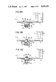
FIG. 3 is a perspective view of a coupling device for electric units in a first embodiment of the present invention;
FIGS. 4A, 4B and 4C are side sectional views showing the coupling steps of both electric devices with the use of the coupling device;
FIG. 5 is a perspective view of a coupling device for electric units in a second embodiment of the present invention;
FIG. 6 is an enlarged perspective view of a main part thereof;
FIG. 7 is a perspective view of a coupling device for electric units in a third embodiment of the present invention;
FIG. 8 is a perspective view of an auxiliary electric device used in connection with the coupling device of the third embodiment;
FIG. 9 is a perspective view of a main part of the same;
FIGS. 10A, 10B and 10C and FIGS. 11A, 11B and 11C are sectional views showing the coupling steps of both electric units with the use of the coupling device of the third embodiment of the present invention;
FIG. 12 is an exploded perspective view of a coupling device for electric units in a fourth embodiment of the present invention; and
FIGS. 13A, 13B and 13C are side sectional views showing the coupling steps of both electric units with the use of the coupling device of the fourth embodiment.
A coupling device in to a first embodiment form of the present invention for coupling a portable video recording unit to a main electric unit including a television tuner will now be described with reference to FIGS. 3 to 4C.
In this coupling device, an shown in FIG. 3, when a portable video recording unit 5 is slide in its horizontal attitude on a main electric unit 6, including a television tuner, from the front side to the rear side (the direction indicated by an arrow), a connector 7 of the video recording unit 5 is disconnectably coupled to a connector 8 of the main electric unit 6.
A slide stopper 9 is mounted in the vicinity of the connector 8 of the main unit 6. This slide stopper 9 is inserted into a bore 19 provided in a mounting surface 6a of the main unit 6, and is mounted in such a manner that a slide plate 10 fixed to the slide stopper 9 is fitted into guide ribs 10a so as to permit this stopper to slide in a direction (a direction directed from the front side toward the back side) in which the portable unit 5 is set on the main unit 6. The slide plate 10 fixed with the slide stopper 9 is formed with a through bore 12 for permitting a head portion 11a of an unlocking or releasing button 11 to pass therethrough as well as through bores 13a and 13b for permitting locking portions 11b therethrough. The distance range in which the bores 12, 13, 13b extend is made equal to a distance between the position of the rear surface of the portable unit 5 where the connectors 7 and 8 have been completely coupled together, as shown in FIG. 4A, and the position of the rear surface of the portable unit 5 where the connectors 7 and 8 have been completely disconnected from each other and as well where the slide stopper abutted against the rear end of the mounting surface 6a of the main unit 6 inhibits the rear surface of the portable unit from making contact with the connector 8 of the main housing, as shown in FIG. 4C.
The unlocking button 11 is inserted from below, through the bore 12 of the slide plate 10 and a bore 14 formed in the main unit, and is urged upwards from below by means of a spring 16 having its one end fixed to the underside of the main unit 6 by, for example, a screw thereby, the unlocking button 11 is vertically movable. To the slide plate 10 is attached one end 17a of a spring 17, the other end of which is fixed to the underside of the main unit 6, whereby the slide stopper 9 is pulled in the forward direction.
With this arrangement, when, as shown in FIG. 4A, the portable unit 5 is positioned in its horizontal attitude and is set on the main unit 6 from a specified direction and slid backwards, the unlocking button 11 is depressed by the underside of the portable unit 5 and is disengaged from the bore 13a of the slide plate 10, resulting in unlocking the slide plate 10. When the portable unit 5 is pushed to the main unit 6 in this state, the rear face of the portable unit 5 abuts against the front wall 9a of the slide stopper 9. Thus, the slide stopper 9 is slid backwards overcoming the urging force of the spring 17 together with the portable unit 5, thereby the connectors 7 and 8 of the portable unit 5 and main unit 6 are surely coupled to each other, with the connector being held in the specified horizontal posture.
When the connectors 7 and 8 have been completely coupled together, as shown in FIG. 4B the locking portions 11b of the unlocking button 11 are fitted into the bores 13b of the slide plate 10, and therefore, the head portion 11a of the same is moved upwards to enter a recess portion 18 provided in the underside of the deck 5. Thus, in this state, the slide plate 10 fixed with the slide stopper 9 is locked again. As a result, the pulling force of the spring 17 is ineffective to the portable unit 5 and thus the coupling between both connectors 7 and 8 becomes secure.
However, when, as shown in FIG. 4C, an attempt is made to mount the portable unit 5 in directions other than the specified horizontal direction, such as, for example, a direction obliquely downward, onto the mounting surface of the main unit 6, a gap is created between the underside of the portable unit 5 and the main unit 6, resulting in that the unlocking button 11 fails to be depressed. Thus, the locking portion 11b of the unlocking button 11 is held, fitted in the bore 13a of the slide plate 10 fixed with the slide stopper 9. That is, the slide plate 10 is held locked, so that the slide stopper 9 does not slide backwards. In this state, therefore, due to no backward slide of the slide stopper 9 even when the portable unit 5 is pushed backwards, it is impossible to couple the connectors 7 and 8 together. Accordingly, the portable unit 5 can not be coupled to the main unit 6 when it is mounted in a direction other than the abovementioned specified horizontal direction. According to this first embodiment of the present invention, therefore, it is possible to disconnectably couple the connectors together without causing any damage thereto.
The coupling device according to the present invention is not limited to the arrangement described above. That is to say, the coupling device may also be arranged such that the slide stopper 9 is allowed to slide vertically. Further, if a locking means is provided to the connectors 7, 8, the slide plate 10 fixed to the slide stopper 9 may have only one pair of locking bores and a slit for sliding the unlocking button 11.
In FIG. 5, a second embodiment of the present invention is shown.
In this embodiment, a slide stopper 9 and a locking member 20 are provided separately from each other, and a left checking member 21 for preventing the front portion of the portable unit 5 from being upwardly separated from the main device 6 is provided.
The slide stopper 9 is disposed such that its stopper portion protrudes from a window 19 of the main electric unit 6, and a slide plate 10 fixed with the stopper 9 is supported by guide ribs 10a in such a manner that it is slidable in the back-and-forth direction. The slide plate 10 is also forwardly urged by the spring 17. Further, the head portion 11a of the unlocking button 11 is inserted through bores 12, 14, protruding from the top surface of the main device 6. At the same time, the locking portions 11b are fitted into the bores 13, respectively. The unlocking button 11 is upwardly urged by means of a spring 16.
The locking member 20 is disposed such that its push button section 20a protrudes from a window 22 in the main unit 6 and such that its locking portion 20b protrudes from the top surface of the main unit 6 through a bore 23. The locking member 20 is upwardly urged by means of a spring 24, being vertically movable.
Further, the lift checking member 21 is mounted such that its checking portion 21a is inserted through a bore 26 of a support plate 25 and it is supported in such a manner that it is upwardly urged by means of a spring 27. Further, the checking portion 21a of the lift checking member 21 inserted, from below, through a bore 27 of the main device 6, protruding from the top surface of the same. Further, the support plate 25 is held by guide ribs 28 so as to be slidable in the forward or backward direction. This support plate 25 is forwardly urged by means of a spring 29.
The underside of the connectable electric unit 5 is formed with a recess portion 18 to be engaged with the locking portion 20b of the locking member 20, as well as a recess portion 30 to be engaged with the checking portion 21a of the lift checking portion 21. This recess portion 30 is formed, as shown in FIG. 6, with an engaging portion 30a which is intended to prevent the connectable unit 5 from lifting off the main electric unit 6, owing to the engagement with an L-shaped tip end portion of the checking portion 21a.
With the above-mentioned arrangement, the connectable electric unit 5 is coupled to the main electric unit 6 as follows. First of all, the connectable electric unit 5 is placed on the top surface of the main device 6. Only when connectable unit 5 is surely placed without being set on the main unit 6 obliquely downward, the head portion 11a of the unlocking button 11 is depressed by the underside of the connectable electric unit 5. Thus, the locking of the slide stopper 9 is released and, in this state, the connectable unit 5 is backwardly pushed, whereby the front wall 9a of the slide stopper 9 is pushed backward overcoming the pulling force of the spring 17. Consequently, the connectors 7 and 8 of the two units 5, 6 are coupled together. When the connectable unit 5 is set obliquely downward onto the main device 6, the head portion 11a is not depressed, resulting in that the slide stopper 9 is held locked. Thus, the connectors cannot be coupled together if connectable unit 5 is set on the main unit 7 in a posture other than the specified posture.
When the connectable electric unit 5 is correctly coupled to the main electric unit 6, the locking portion 20b of the locking member 20 is brought into engagement with the recess portion 18 of the connectable unit 5, to prevent the same from being forwardly moved. When the connectable unit 5 is pressed to the back side of the main device 6, the checking portion 21a of the lift checking member 21 is brought into engagement with the engaging portion 30a of the recess portion 30 of the connectable unit 5, resulting in that the connectable unit 5 is prevented from being lifted from the main device 6. Thus, the connectable unit 5 is held correctly mounted on and coupled to the main unit 6.
Next, when the connectable unit 5 is dismounted, the push button section 20a of the locking member 20 is manually depressed by an operator. Then, the locking member 20 is downwardly moved so that its locking portion 20b is disengaged from the recess portion 18 of the connectable unit 5. As a result, the connectable unit 5 is unlocked and, therefore, the connectable unit 5 is pushed forwards by the front wall 9a of the slide stopper 9 due to the pulling force of the spring 17. Thus, the coupling between the connectors 7 and 8 is made ineffective. At the same time, as the connectable unit 5 is moved forwards, the engaging portion 30a of the recess portion 30 is disengaged from the L-shaped tip end portion 21a of the lift checking member 21. Thus, the connectable unit 5 is dismounted from the main unit 6.
In this way, according to the second embodiment of the present invention, it is possible to disconnectably couple the connectable unit 5 from the main electric unit 6 in a short time. However, this can be made only when the connectable unit is correctly set on the main unit in order to couple both connectors. Thus, the connectors can be prevented from being damaged or broken.
Next, a coupling device according to a third embodiment of the present invention will be described with reference to FIGS. 7 to 11.
The coupling device according to this embodiment comprises a main electric unit 6, unit 5 which can be mounted to the main unit 6 by sliding the same rearwardly and which can be dismounted therefrom by sliding the same forwardly, a connector provided on the main unit, and a connector provided on the connectable unit and arranged to be connected with the connector of the main unit. In this coupling device, a recessed portion or depression is formed in either one of the main unit or connectable unit. This depression is provided, on its front wall, with a projection facing rearward. The other one of both units is provided with a stopper which is extendable and retractable and is also movable in the back-and-forth direction. This stopper is provided with a locking piece which is L-shaped in vertical section and which is fitted into the above-mentioned depression to be engaged with the projection provided on the front wall of the depression, as well as a withdrawal or disengagement preventing piece which is extendable and retractable between the locking piece and a back wall of the depression, whereby, when the stopper has been moved forwards, the disengagement preventing piece can be retracted, or is retreated below the upper surface of the main unit 6.
In this coupling device as shown in FIGS. 7 to 9, the connectable electric unit 5 such as, for example, a portable unit is arranged to slide on the main electric device 6 having a television tuner incorporated therein from the front side toward the back side thereof (the direction indicated by an arrow), with the connectable unit being positioned in its horizontal posture, thereby the connector 7 provided on the connectable unit is disconnectably coupled to the connector 8 provided on the main unit. A recessed portion 39 is formed in the underside of the connectable unit 5. On the front wall of this recessed portion 39 there is provided the projection 40 extending backwards, on both sides of which are provided inclined surfaces 41. At the rear wall of the recessed portion 39 there is provided a surface 42 vertical with respect to the bottom surface of the connectable unit 5, on both side ends of which there are provided inclined surfaces 43, respectively.
Onto the main unit 6, a stopper case 44 is mounted by way of guide ribs 45 so that this stopper case 44 is slidable in a direction in which the connectable unit 5 is mounted, i.e., a direction directed from the front side toward the back side of the main unit 6. At the front portions of these guide ribs 45 are provided ribs inclined in the direction in which the stopper case 44 can be slid. Further, a stopper 48 is mounted so that it is inserted through a bore 47 of the main unit 6 from below the stopper case 44. The stopper 48 is fitted into the recessed portion 39 provided in the connectable unit 5 and is engaged with the projection 40 provided on the front wall of the recessed portion 39. Its vertical section is shaped like a letter L. Further, the stopper 48 is also provided, on both sides of its L-shaped portion, with inclined ribs 49 to be engaged with the inclined surfaces 41 and 43 provided in the recessed portion 39 of the connectable unit 5. In the rear portion of the stopper 48, a through bore 51 is provided, which through bore 51 is engaged with the disengagement preventing member piece 50. Further, the stopper 48 is also provided, at its bottom, with a guide pin 52. The disengagement preventing piece 50 is fitted, from below, into a bore 51 provided in the stopper 48. The disengagement preventing piece 50 is fitted between the back of the stopper 48 engaged with the projection 40 formed in the connectable unit 5 and the back wall 42 provided in the same. The disengagement preventing piece 50 is provided, on its right and left sides, with inclined ribs 54 which are engaged with the inclined ribs 46 provided on the main electric unit 6, respectively. Further, the disengagement preventing piece 50 is provided, at its bottom surface, with a guide pin 55.
Coil springs 56 are fitted, from below, onto the guide pins 52, 55 provided on the stopper 48 and the disengagement preventing piece 50, respectively. A case cover 57 is mounted, from below, onto the stopper case 44 so that the stopper 48 and the disengagement preventing piece 50 may be vertically movable. The stopper 48 and the disengagement preventing piece 50 are arranged such that when the stopper 48 is depressed downwards, the latter piece 50 is moved downwards together with the former 48; and when the disengagement preventing piece 50 is depressed downwards, the stopper 48 is not moved at all but the piece 50 alone is moved. The stopper case 44 is attached with one end 58a of a spring 58, the other end 58b of which is fixed to the main unit 6, thereby the stopper case 44 is held forwardly pulled.
In operation, as shown in FIG. 10A, when the connectable unit 5 is directed in a specified direction while being positioned in its horizontal position and placed on the main unit 6, the stopper 48 and the disengagement preventing piece 50 are pushed downwards. Next, as shown in FIG. 10B, when, in this state, the connectable unit 5 is slid backwards, the stopper 48 is fitted into the recessed portion 39 provided in the bottom surface of the connectable unit 5, and is slid upwards by the action of the coil spring 56. Next, as shown in FIG. 10C, when the connectable unit 5 is further slid backwards, the stopper 48 is engaged with the rearwardly extending projection 40 provided on the front wall of the recessed portion 39, resulting in that the unit 5 is prevented from being lifted from the main unit 6. Further, the disengagement preventing piece 50 is fitted between the back wall of the stopper 48 and the back wall 42 of the recessed portion 39 of the connectable unit 5, resulting in that the engagement of the connectable unit 5 with the stopper 48 is reliably effected. Thus, the respective connectors 7 and 8 of the connectable unit 5 and the main unit 6 are correctly coupled together, held in a specified horizontal posture.
Where the connectable unit 5 is coupled to the main unit 6 as shown in FIG. 11A, since the projection 40 of the recessed portion 39 provided in the connectable unit 5 is engaged with the stopper 48, it is impossible to lift the connectable unit 5 from the main unit 6.
On the other hand, when the connectable unit 5 is dismounted from the main unit 6, as shown in FIG. 11B forward sliding of the auxiliary device 5 held in its horizontal posture would cause the inclined ribs 54 provided on the disengagement preventing piece 50 to be guided by the inclined ribs 46 provided on the main device 6, resulting in that the disengagement preventing piece 50 is depressed downwards. Further forward sliding of the connectable unit 5 would permit the stopper 48 to rise in the bore 47 of the main device 6 so that the stopper 48 is disengaged from the projection 40 as shown in FIG. 11C. More further forward sliding of the connectable unit 5 would cause the inclined ribs 49 of the stopper 48 to be pushed by the inclined surfaces 43 provided in the connectable unit 5. Thus, the stopper 48 is pushed downwards, whereby the unit 5 can be dismounted from the main unit 6.
Where an attempt is made to dismount the unit 5 in such a condition the connectors 7 and 8 are coupled to each other, the engagement of the stopper 48 with the projection 40 of the recessed portion 39 provided in the connectable unit 5 makes it impossible to lift the connectable unit 5 from the main unit 6. That is to say, the connectable unit 5 can not slide on the main unit 6 unless in a specified horizontal direction. For this reason, no extraordinary load is applied to the connectors 7 and 8. That is, these connectors can be disconnectably coupled to each other without being broken or damaged.
Having above described the third embodiment of the present invention, the arrangement of the coupling device is not limited to those which have been described hereinbefore. A coupling device wherein the stopper is added to the connectable electric unit 5 can be also included within the scope of the present invention.
Further, the coupling device of the present invention is also applicable to a coupler for coupling a small-sized wireless unit and a main electric unit having a power amplifier incorporated therein.
A coupling device according to a fourth embodiment of the present invention is shown in FIG. 12.
The coupling device of this embodiment is arranged such that the connector 7 of the portable VTR unit 5 is disconnectably coupled to the connector 8 of the main electric unit 6 having a television tuner, etc. incorporated therein, by being slid thereon from the front side toward the back side (the direction indicated by the arrow) with the unit 5 being held in its horizontal posture, as in the prior coupling device. In this embodiment, the stopper 9 is mounted in the vicinity of the connector 8 of the main device 6. This slide stopper 9 is fixed to the slide plate 10 and this slide plate 10 is mounted on the main unit 6 by way of the guide ribs 10a so that it can be slid in the mounting direction of the VTR 5, i.e., in the backward direction thereof. The stopper 9 can protrude from the sliding surface 6a of the main unit 6 via the through bore 19 provided therein. Further, the slide plate 10 is provided with bores 57 and 58 which have a width l2 greater than the width l3 of a flange portion 11c of the unlocking button 11 and which allow this flange portion 11c to pass and which are spaced from each other at a specified interval. The space between these two bores 57, 58 corresponds to the distance between the position of the front wall 9a of the slide stopper 9, which corresponds to the position of the back surface of the unit 5 when the connectors 7 and 8 have been completely coupled together, and the position of the front wall 9a of the slide stopper 9, which corresponds to the position of the back surface of the unit 5 when both connectors have been completely disconnected from each other. Further, both bores 57 and 58 are communicated with each other through a slit having a width l1 permitting the head portion 11a of the unlocking button 11 to pass through this slit. That is, this width l1 is made greater than the width of the head portion 11a of the unlocking button and made smaller than the width l3 of the flange portion 11c of the unlocking button 11.
The unlocking button 11 is inserted from below, through the slide plate 10 and the through bore 14 of the main unit 6 and is pressed upward by the spring 16 having one end fixed onto the underside of the main unit 6 by means of, for example, a screw so that the unlocking button 11 is vertically movable. One end 17a of the spring 17 is attached to one end portion of the slide plate 10 while the other end 17b thereof is fixed to the main unit 6, so as to pull the slide plate 10 in the forward direction.
As shown in FIG. 13A, when the unit 5 is set to the main unit 6 from a specified horizontal direction while being positioned in its horizontal posture on the upper surface of the main unit 6 and then is slid in the backward direction, the unlocking button 11 is pressed downwards, thereby the flange portion 11c thereof is disengaged from the bore 58 of the slide plate 10. Thus, this plate 10 is unlocked.
When, in this state, the unit 5 is pushed to the back side of the main unit 6, its back surface is abutted against the front wall of the deck stopper 9, whereby the slide stopper 9 is backwardly slid together with the unit 5. Thus, the connectors 7 and 8 of the unit 5 and the main unit 6 are surely coupled to each other, both units being held in their horizontal posture. As shown in FIG. 13B, when the connectors 7 and 8 have completely been coupled together, the flange portion 11c of the unlocking button 11 is inserted into the bore 57 of the slide plate 10 and is moved upwards so as to enter into the recessed portion 18 provided in the bottom surface of the deck 5. Then, the slide plate 10 is locked again in this state, resulting that the forwardly pulling force of the spring 17 is ineffective to the unit 5. Thus, the connectors 7 and 8 will not be disconnected, accidentally. However, as shown in FIG. 13C, when at attempt is made to mount the unit 5 directions other than the specified horizontal direction that is, for example, in a direction obliquely on the upper surface of the main unit 6, a gap or space is created between the underside of the unit 5 and the upper surface of the main unit 6, resulting in that the unlocking button 11 is not depressed downwards. For this reason, the flange portion 11c of the unlocking button 11 is held fitted in the bore 58 of the slide plate 10, i.e., the slide plate 10 is held locked. As a consequence, the slide plate 10 is slid backwards. In this state, therefore, even when the unit 5 is pushed backwards, it is impossible to couple the connectors 7 and 8 together. That is, since the unit 5 can not be coupled to the main unit 6 unless it is mounted from the specified horizontal direction, both can be coupled to each other without the connectors being broken or damaged.
Claims (5)
1. A coupling device for electric devices, comprising: a connectable electric unit having a first connector at one end thereof, a main electric unit having a mounting surface on which said connectable unit is to be set, and a second connector provided at one end portion of said mounting surface and adapted to be coupled with said first connector, a stopper projecting from said main electronic unit and movable between a first position where said stopper inhibits said first connector from being coupled with said second connector and a second position where said stopper retracts into said main electrical unit so as to allow the coupling between said first and second connectors, a first means for resiliently urging said stopper toward said first position, a means for locking said stopper at said first position, an unlocking member movable between a third position where said unlocking member projects from said mounting surface and a fourth position where said unlocking member retracts from said mounting surface, a second means for resiliently urging said unlocking member toward said third position, and a means for releasing the locking of said locking means when said unlocking member moves to said fourth position.
2. A coupling device as set forth in claim 1, wherein said stopper is fixed to a slide plate having therein a through-bore through which said unlocking member retractably projects from said mounting surface, and said locking means engages with said slide plate when said unlocking member is in said third position to inhibit said slide plate from sliding, but said locking means disengages from said slide plate when said unlocking member is in said fourth position.
3. A coupling device as set forth in claim 1, wherein said connectable electrical unit has a bottom surface adapted to oppose said mounting surface, said bottom surface having a recess portion therein which allows said unlocking member to project from said mounting surface upon engagement of said first and second connectors.
4. A coupling device as set forth in claim 1, wherein said connectable electrical unit has a bottom surface adapted to oppose said mounting surface, said coupling device further comprising a first locking piece which is movable between a fifth position where said locking piece projects from said mounting surface and a sixth position where said locking piece is retracted for said mounting surface by being pressed by said bottom surface of said connectable electrical unit, a third means for resiliently urging said first locking piece toward said fifth position, a recess portion formed in said bottom surface of said connectable electrical unit and adapted to be engaged with said first locking piece upon coupling between said first and second connectors so as to prevent said connectable electrical unit from sliding on said mounting surface, and a push member for moving said first locking piece toward said sixth position in opposition to a force exerted by said third means for resiliently urging.
5. A coupling device as set forth in claim 1, wherein said connectable electrical unit has a bottom surface adapted to oppose said mounting surface, said coupling device further comprising a lift checking member movable between a seventh position where said lift checking member projects from said mounting surface and an eighth position where said lift checking member is retracted from said mounting surface by being pressed by said bottom surface of said connectable electrical unit, said having a front end formed thereon with a locking portion projecting in parallel with said mounting surface, a fourth means for resiliently urging said checking means toward said seventh position, and a recess portion formed in said bottom surface of said connectable electrical unit and adapted to be engaged with said locking portion upon coupling of said first and second connectors so as to inhibit said connectable electrical unit from being removed from said mounting surface.
Applications Claiming Priority (4)
| Application Number | Priority Date | Filing Date | Title |
|---|---|---|---|
| JP59-41107 | 1984-03-02 | ||
| JP59041107A JPS60185282A (en) | 1984-03-02 | 1984-03-02 | Loading/unloading device of electric apparatus |
| JP59113369A JPH0734376B2 (en) | 1984-06-01 | 1984-06-01 | Device attachment / detachment device |
| JP59-113369 | 1984-06-01 |
Publications (1)
| Publication Number | Publication Date |
|---|---|
| US4659159A true US4659159A (en) | 1987-04-21 |
Family
ID=26380652
Family Applications (1)
| Application Number | Title | Priority Date | Filing Date |
|---|---|---|---|
| US06/706,270 Expired - Fee Related US4659159A (en) | 1984-03-02 | 1985-02-27 | Coupling device for electric devices |
Country Status (2)
| Country | Link |
|---|---|
| US (1) | US4659159A (en) |
| KR (1) | KR900006189B1 (en) |
Cited By (25)
| Publication number | Priority date | Publication date | Assignee | Title |
|---|---|---|---|---|
| US4755150A (en) * | 1987-06-05 | 1988-07-05 | Unisys Corporation | Memory cartridge security locking device |
| FR2630266A1 (en) * | 1988-04-19 | 1989-10-20 | Deutsch Co | Device for locking an electrical connector module |
| EP0448053A2 (en) * | 1990-03-20 | 1991-09-25 | Kabushiki Kaisha Toshiba | Expanding apparatus for portable electronic apparatus |
| US5619397A (en) * | 1994-09-29 | 1997-04-08 | Kabushiki Kaisha Toshiba | Electronic device system including a portable electronic device having a handwriting input device locked to an expansion station when the power switch of the portable electronic device is turned on |
| US5684673A (en) * | 1993-09-30 | 1997-11-04 | Kabushiki Kaisha Toshiba | Electronic system having a portable electronic apparatus and an extention unit for extending functions of the portable electronic apparatus |
| US5692400A (en) * | 1996-03-25 | 1997-12-02 | Hewlett-Packard Company | Securing portable computers and associated docking systems |
| US5784253A (en) * | 1995-10-20 | 1998-07-21 | Kabushiki Kaisha Toshiba | Docking station including ejection lever located under computer mounted on docking station and cover held closed by portion extending under computer |
| US5838539A (en) * | 1995-11-08 | 1998-11-17 | Electronics Accessory Specialists International | Docking module for portable computers |
| US5862036A (en) * | 1997-04-08 | 1999-01-19 | Inventec Corporation | Dock for connecting a notebook computer to a PC |
| US6061233A (en) * | 1998-01-13 | 2000-05-09 | Samsung Electronics Co., Ltd. | Docking station for a laptop computer |
| USRE36695E (en) * | 1995-07-25 | 2000-05-16 | Dell U.S.A., L.P. | Captive latch mechanism for use with an expansion card cage in a personal computer |
| US6093039A (en) * | 1998-08-06 | 2000-07-25 | Mobility Electronics, Inc. | Docking device for a portable computer |
| US6115246A (en) * | 1996-11-05 | 2000-09-05 | Fujitsu Limited | Function extending apparatus for information processing device |
| US6301116B1 (en) * | 1996-07-19 | 2001-10-09 | Sony Corporation | Auxiliary device for electronic apparatus |
| US6411537B2 (en) * | 1998-04-30 | 2002-06-25 | Hewlett-Packard Company | Portable computer and system having an alignment mechanism |
| US6490155B2 (en) * | 2000-07-07 | 2002-12-03 | Palm, Inc. | Detachable coupling for handheld computer and peripheral attachment scheme |
| US6493230B2 (en) * | 2001-05-01 | 2002-12-10 | Sun Microsystems, Inc. | Modular computer system mechanical interconnection |
| US20080002354A1 (en) * | 2006-06-30 | 2008-01-03 | Carnevali Jeffrey D | Portable device docking station |
| WO2009030315A1 (en) * | 2007-08-31 | 2009-03-12 | Phoenix Contact Gmbh & Co. Kg | Locking mechanism for a housing to hold a plug-in module |
| US20090213536A1 (en) * | 2008-02-27 | 2009-08-27 | Lewandowski Jason M | Computer docking station for a vehicle |
| US20100136397A1 (en) * | 2008-11-28 | 2010-06-03 | Chi Mei Communication Systems, Inc. | Battery holding structure |
| US20130214105A1 (en) * | 2012-02-21 | 2013-08-22 | L-3 Communication Avionics Systems, Inc. | Retention mechanism and method for removeably supporting a portable flight controller |
| TWI425339B (en) * | 2008-12-19 | 2014-02-01 | Chi Mei Comm Systems Inc | Battery fixing device |
| US20160349793A1 (en) * | 2015-05-27 | 2016-12-01 | Fujitsu Limited | Expansion device and electronic apparatus |
| US20190132967A1 (en) * | 2017-10-30 | 2019-05-02 | 3Y Power Technology (Taiwan), Inc. | Locking spring structure and power apparatus having the same |
Citations (9)
| Publication number | Priority date | Publication date | Assignee | Title |
|---|---|---|---|---|
| US3020511A (en) * | 1958-06-25 | 1962-02-06 | Gen Dynamics Corp | Electrical connector |
| US3035243A (en) * | 1961-04-03 | 1962-05-15 | Gen Electric | Lever mechanism for multiple electrical connectors |
| US3209301A (en) * | 1960-09-12 | 1965-09-28 | Fed Pacific Electric Co | Plug-in bus duct |
| US3599167A (en) * | 1969-04-10 | 1971-08-10 | Deutsch Co Elec Comp | Three-unit electrical connector |
| US3977749A (en) * | 1975-01-29 | 1976-08-31 | International Telephone And Telegraph Corporation | Electronic packaging assembly |
| US4040698A (en) * | 1976-10-12 | 1977-08-09 | Nilson V. Ortiz | Electrical safety outlet and plug |
| US4141616A (en) * | 1977-11-11 | 1979-02-27 | Motorola, Inc. | Unitized connector arrangement for electrical apparatus |
| FR2402317A1 (en) * | 1977-08-30 | 1979-03-30 | Voegtlin Jacques | Electrical plug and socket connector - has spring loaded disc cover for socket which does not uncover live contacts until plug is pushed fully home |
| US4288684A (en) * | 1977-10-18 | 1981-09-08 | Kato Hisao | Electrode type steam vaporizer |
-
1985
- 1985-02-27 US US06/706,270 patent/US4659159A/en not_active Expired - Fee Related
- 1985-03-02 KR KR1019850001323A patent/KR900006189B1/en not_active IP Right Cessation
Patent Citations (9)
| Publication number | Priority date | Publication date | Assignee | Title |
|---|---|---|---|---|
| US3020511A (en) * | 1958-06-25 | 1962-02-06 | Gen Dynamics Corp | Electrical connector |
| US3209301A (en) * | 1960-09-12 | 1965-09-28 | Fed Pacific Electric Co | Plug-in bus duct |
| US3035243A (en) * | 1961-04-03 | 1962-05-15 | Gen Electric | Lever mechanism for multiple electrical connectors |
| US3599167A (en) * | 1969-04-10 | 1971-08-10 | Deutsch Co Elec Comp | Three-unit electrical connector |
| US3977749A (en) * | 1975-01-29 | 1976-08-31 | International Telephone And Telegraph Corporation | Electronic packaging assembly |
| US4040698A (en) * | 1976-10-12 | 1977-08-09 | Nilson V. Ortiz | Electrical safety outlet and plug |
| FR2402317A1 (en) * | 1977-08-30 | 1979-03-30 | Voegtlin Jacques | Electrical plug and socket connector - has spring loaded disc cover for socket which does not uncover live contacts until plug is pushed fully home |
| US4288684A (en) * | 1977-10-18 | 1981-09-08 | Kato Hisao | Electrode type steam vaporizer |
| US4141616A (en) * | 1977-11-11 | 1979-02-27 | Motorola, Inc. | Unitized connector arrangement for electrical apparatus |
Cited By (46)
| Publication number | Priority date | Publication date | Assignee | Title |
|---|---|---|---|---|
| US4755150A (en) * | 1987-06-05 | 1988-07-05 | Unisys Corporation | Memory cartridge security locking device |
| FR2630266A1 (en) * | 1988-04-19 | 1989-10-20 | Deutsch Co | Device for locking an electrical connector module |
| EP0448053A2 (en) * | 1990-03-20 | 1991-09-25 | Kabushiki Kaisha Toshiba | Expanding apparatus for portable electronic apparatus |
| EP0448053A3 (en) * | 1990-03-20 | 1992-09-23 | Kabushiki Kaisha Toshiba | Expanding apparatus for portable electronic apparatus |
| US5684673A (en) * | 1993-09-30 | 1997-11-04 | Kabushiki Kaisha Toshiba | Electronic system having a portable electronic apparatus and an extention unit for extending functions of the portable electronic apparatus |
| US5619397A (en) * | 1994-09-29 | 1997-04-08 | Kabushiki Kaisha Toshiba | Electronic device system including a portable electronic device having a handwriting input device locked to an expansion station when the power switch of the portable electronic device is turned on |
| US5751547A (en) * | 1994-09-29 | 1998-05-12 | Kabushiki Kaisha Toshiba | Electronic device system including a portable electronic device having a handwriting input device locked to an expansion station when the power switch of the portable electronic device is turned on |
| USRE36695E (en) * | 1995-07-25 | 2000-05-16 | Dell U.S.A., L.P. | Captive latch mechanism for use with an expansion card cage in a personal computer |
| US5784253A (en) * | 1995-10-20 | 1998-07-21 | Kabushiki Kaisha Toshiba | Docking station including ejection lever located under computer mounted on docking station and cover held closed by portion extending under computer |
| US5838539A (en) * | 1995-11-08 | 1998-11-17 | Electronics Accessory Specialists International | Docking module for portable computers |
| US5692400A (en) * | 1996-03-25 | 1997-12-02 | Hewlett-Packard Company | Securing portable computers and associated docking systems |
| US6047572A (en) * | 1996-03-25 | 2000-04-11 | Hewlett-Packard Company | Docking station with multi-function security feature |
| US6301116B1 (en) * | 1996-07-19 | 2001-10-09 | Sony Corporation | Auxiliary device for electronic apparatus |
| US6115246A (en) * | 1996-11-05 | 2000-09-05 | Fujitsu Limited | Function extending apparatus for information processing device |
| US6556436B2 (en) | 1996-11-05 | 2003-04-29 | Fujitsu Limited | Function extending apparatus for information processing device |
| US6233145B1 (en) | 1996-11-05 | 2001-05-15 | Fujitsu Limited | Function extending apparatus for information processing device |
| US5862036A (en) * | 1997-04-08 | 1999-01-19 | Inventec Corporation | Dock for connecting a notebook computer to a PC |
| US6061233A (en) * | 1998-01-13 | 2000-05-09 | Samsung Electronics Co., Ltd. | Docking station for a laptop computer |
| US6411537B2 (en) * | 1998-04-30 | 2002-06-25 | Hewlett-Packard Company | Portable computer and system having an alignment mechanism |
| US6093039A (en) * | 1998-08-06 | 2000-07-25 | Mobility Electronics, Inc. | Docking device for a portable computer |
| US6490155B2 (en) * | 2000-07-07 | 2002-12-03 | Palm, Inc. | Detachable coupling for handheld computer and peripheral attachment scheme |
| US6781844B2 (en) * | 2001-05-01 | 2004-08-24 | Sun Microsystems, Inc. | Modular computer system mechanical interconnection |
| US7352589B2 (en) | 2001-05-01 | 2008-04-01 | Sun Microsystems, Inc. | Modular computer system mechanical interconnection |
| US20050002166A1 (en) * | 2001-05-01 | 2005-01-06 | Sun Microsystems, Inc. | Modular computer system mechanical interconnection |
| US6493230B2 (en) * | 2001-05-01 | 2002-12-10 | Sun Microsystems, Inc. | Modular computer system mechanical interconnection |
| US9036343B2 (en) | 2006-06-30 | 2015-05-19 | National Products, Inc. | Portable device docking station |
| US20080002354A1 (en) * | 2006-06-30 | 2008-01-03 | Carnevali Jeffrey D | Portable device docking station |
| US8179672B2 (en) | 2006-06-30 | 2012-05-15 | National Products, Inc. | Portable device docking station |
| WO2009030315A1 (en) * | 2007-08-31 | 2009-03-12 | Phoenix Contact Gmbh & Co. Kg | Locking mechanism for a housing to hold a plug-in module |
| US8472200B2 (en) | 2007-08-31 | 2013-06-25 | Phoenix Contact Gmbh & Co. Kg | Locking mechanism for a housing to hold a plug-in module |
| US20100202116A1 (en) * | 2007-08-31 | 2010-08-12 | Phoenix Contact Gmbh & Co. Kg | Locking mechanism for a housing to hold a plug-in module |
| US7978466B2 (en) | 2008-02-27 | 2011-07-12 | L&P Property Management Company | Computer docking station for a vehicle |
| US8098488B2 (en) * | 2008-02-27 | 2012-01-17 | L&P Property Management Company | Computer docking station for a vehicle |
| US20090213536A1 (en) * | 2008-02-27 | 2009-08-27 | Lewandowski Jason M | Computer docking station for a vehicle |
| US20110128689A1 (en) * | 2008-02-27 | 2011-06-02 | Lewandowski Jason M | Computer docking station for a vehicle |
| USRE43869E1 (en) | 2008-02-27 | 2012-12-25 | L&P Property Management Company | Computer docking station for a vehicle |
| CN101752519B (en) * | 2008-11-28 | 2013-11-06 | 深圳富泰宏精密工业有限公司 | Battery fixing device |
| US20100136397A1 (en) * | 2008-11-28 | 2010-06-03 | Chi Mei Communication Systems, Inc. | Battery holding structure |
| US8101294B2 (en) * | 2008-11-28 | 2012-01-24 | Chi Mei Communication Systems, Inc. | Battery holding structure |
| TWI425339B (en) * | 2008-12-19 | 2014-02-01 | Chi Mei Comm Systems Inc | Battery fixing device |
| US20130214105A1 (en) * | 2012-02-21 | 2013-08-22 | L-3 Communication Avionics Systems, Inc. | Retention mechanism and method for removeably supporting a portable flight controller |
| US9169964B2 (en) * | 2012-02-21 | 2015-10-27 | L-3 Communications Avionics Systems, Inc. | Retention mechanism and method for removeably supporting a portable flight controller |
| US20160349793A1 (en) * | 2015-05-27 | 2016-12-01 | Fujitsu Limited | Expansion device and electronic apparatus |
| US9910457B2 (en) * | 2015-05-27 | 2018-03-06 | Fujitsu Limited | Expansion device and electronic apparatus |
| US20190132967A1 (en) * | 2017-10-30 | 2019-05-02 | 3Y Power Technology (Taiwan), Inc. | Locking spring structure and power apparatus having the same |
| US10617024B2 (en) * | 2017-10-30 | 2020-04-07 | 3Y Power Technology (Taiwan), Inc. | Locking spring structure and power apparatus having the same |
Also Published As
| Publication number | Publication date |
|---|---|
| KR900006189B1 (en) | 1990-08-25 |
| KR850006848A (en) | 1985-10-16 |
Similar Documents
| Publication | Publication Date | Title |
|---|---|---|
| US4659159A (en) | Coupling device for electric devices | |
| EP1369964B1 (en) | Connector Position Assurance Device | |
| EP1571734B1 (en) | Connector apparatus with a mating detecting member called connector position assurance | |
| US4881839A (en) | Portable electronic data handling/data entry system | |
| US6857892B2 (en) | Electrical connector with connector position assurance member | |
| US6692288B2 (en) | Connector with detector for detecting incomplete connection and for protecting resilient lock arm of connector | |
| US20040067676A1 (en) | Connector | |
| EP0968549B1 (en) | Initiation connector for airbag systems | |
| US6059597A (en) | Half-fitting prevention connector | |
| EP0554827A2 (en) | Connector capable of automatically and reliably inhibiting disengagement of mechanical coupling between connection members | |
| JPS61214500A (en) | Plug aid | |
| US6173843B1 (en) | Computer expansion card latching and retention mechanism | |
| US7575453B2 (en) | Electronic module locking and ejecting apparatus | |
| TWM604975U (en) | Combination of first connector, second connector and electric connector | |
| US6282099B1 (en) | Structure for mounting and method for installing a circuit card | |
| US6749455B2 (en) | Connector | |
| TW202224284A (en) | Pull strap connector and assembly of the pull strap connector | |
| JPH06266472A (en) | Attaching and detaching mechanism for display device | |
| US4668036A (en) | Large picture display device | |
| US6319041B1 (en) | Connector with positive locking features | |
| JPS60257088A (en) | Device detachably attaching device | |
| JP2907258B2 (en) | Connector lock security member | |
| JP3032942B2 (en) | connector | |
| JP3285546B2 (en) | Lock release mechanism for adapters, etc. | |
| JP2511387Y2 (en) | Connector with release mechanism |
Legal Events
| Date | Code | Title | Description |
|---|---|---|---|
| AS | Assignment |
Owner name: MATSUSHITA ELECTRIC INDUSTRIAL CO., LTD., 1006, OA Free format text: ASSIGNMENT OF ASSIGNORS INTEREST.;ASSIGNOR:TAKAHASHI, SHIGEKI;REEL/FRAME:004421/0179 Effective date: 19850219 |
|
| FPAY | Fee payment |
Year of fee payment: 4 |
|
| FEPP | Fee payment procedure |
Free format text: PAYOR NUMBER ASSIGNED (ORIGINAL EVENT CODE: ASPN); ENTITY STATUS OF PATENT OWNER: LARGE ENTITY |
|
| REMI | Maintenance fee reminder mailed | ||
| LAPS | Lapse for failure to pay maintenance fees | ||
| FP | Lapsed due to failure to pay maintenance fee |
Effective date: 19950426 |
|
| STCH | Information on status: patent discontinuation |
Free format text: PATENT EXPIRED DUE TO NONPAYMENT OF MAINTENANCE FEES UNDER 37 CFR 1.362 |