US4547706A - Inverter with a load circuit containing a series oscillating circuit and a discharge lamp - Google Patents
Inverter with a load circuit containing a series oscillating circuit and a discharge lamp Download PDFInfo
- Publication number
- US4547706A US4547706A US06/561,675 US56167583A US4547706A US 4547706 A US4547706 A US 4547706A US 56167583 A US56167583 A US 56167583A US 4547706 A US4547706 A US 4547706A
- Authority
- US
- United States
- Prior art keywords
- voltage
- oscillating circuit
- capacitor
- inverter
- dependent resistor
- Prior art date
- Legal status (The legal status is an assumption and is not a legal conclusion. Google has not performed a legal analysis and makes no representation as to the accuracy of the status listed.)
- Expired - Lifetime
Links
Images

Classifications
-
- H—ELECTRICITY
- H05—ELECTRIC TECHNIQUES NOT OTHERWISE PROVIDED FOR
- H05B—ELECTRIC HEATING; ELECTRIC LIGHT SOURCES NOT OTHERWISE PROVIDED FOR; CIRCUIT ARRANGEMENTS FOR ELECTRIC LIGHT SOURCES, IN GENERAL
- H05B41/00—Circuit arrangements or apparatus for igniting or operating discharge lamps
- H05B41/14—Circuit arrangements
- H05B41/26—Circuit arrangements in which the lamp is fed by power derived from dc by means of a converter, e.g. by high-voltage dc
- H05B41/28—Circuit arrangements in which the lamp is fed by power derived from dc by means of a converter, e.g. by high-voltage dc using static converters
- H05B41/295—Circuit arrangements in which the lamp is fed by power derived from dc by means of a converter, e.g. by high-voltage dc using static converters with semiconductor devices and specially adapted for lamps with preheating electrodes, e.g. for fluorescent lamps
- H05B41/298—Arrangements for protecting lamps or circuits against abnormal operating conditions
- H05B41/2981—Arrangements for protecting lamps or circuits against abnormal operating conditions for protecting the circuit against abnormal operating conditions
- H05B41/2985—Arrangements for protecting lamps or circuits against abnormal operating conditions for protecting the circuit against abnormal operating conditions against abnormal lamp operating conditions
-
- Y—GENERAL TAGGING OF NEW TECHNOLOGICAL DEVELOPMENTS; GENERAL TAGGING OF CROSS-SECTIONAL TECHNOLOGIES SPANNING OVER SEVERAL SECTIONS OF THE IPC; TECHNICAL SUBJECTS COVERED BY FORMER USPC CROSS-REFERENCE ART COLLECTIONS [XRACs] AND DIGESTS
- Y10—TECHNICAL SUBJECTS COVERED BY FORMER USPC
- Y10S—TECHNICAL SUBJECTS COVERED BY FORMER USPC CROSS-REFERENCE ART COLLECTIONS [XRACs] AND DIGESTS
- Y10S315/00—Electric lamp and discharge devices: systems
- Y10S315/07—Starting and control circuits for gas discharge lamp using transistors
Definitions
- the invention relates to an inverter having first and second switches connected in series across a DC source. When one of the switches is conducting, the other is open.
- a voltage-dependent resistor which, either alone or as a part of a voltage divider in series with a further voltage divider element, forms a parallel branch to the choke or to the capacitor of the series oscillating circuit.
- the characteristic of a voltage-dependent resistor exhibits a first range in which practically no current flows up to a specific limit voltage.
- the active range then follows in which the characteristic is as steep as possible.
- the voltage-dependent resistor blocks practically up to the limit voltage in both directions and has a resistance which is in practice very low for voltages lying thereabove. Given a corresponding matching of the limit voltage of the voltage-dependent resistor to the parameters of the inverter and its load circuit, it can be achieved that the voltage-dependent resistor functions in the current-conducting range during an ignition mode of the lamps. Should an impermissably high voltage attempt to occur at the components of the series oscillating circuit, then the voltage-dependent resistor forms a decay factor or attenuation of the oscillating circuit which results in a voltage rise that is correspondingly significantly lower.
- the voltage-dependent resistor is dimensioned such that it conducts practically no current when the lamp has lit.
- the series oscillating circuit is damped by the lamp or is completely inactive.
- the voltage at the components of the load circuit is limited to the lower maintaining voltage of the lamp.
- the voltage-dependent resistor can be connected parallel to the capacitor or the choke of the series oscillating circuit.
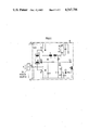
- FIG. 1 is a schematic diagram of a preferred embodiment of the invention.
- FIG. 2 is a graph showing a dependency between frequency and voltage at a discharge lamp used in the circuit shown in FIG. 1.
- the inverter W is connected over terminals w1, w2 to a dc power source H which is fed by an alternating voltage network N and which supplies a d.c. voltage to the inverter.
- the load circuit lies parallel to a close-open path of V1, this load circuit comprising a series connection of a coupling capacitor C1, a discharge lamp E having heatable electrodes e1, e2, an oscillating circuit choke L, and a primary winding t1 of a saturation transformer T.
- the electrodes e1, e2 of the lamp E are connected in series via an oscillating circuit capacitor C, this oscillating circuit capacitor C and the oscillating circuit choke L defining a resonant frequency f 0 .
- the two transistors V1, V2 are alternately driven by a firing unit S.
- the firing unit contains secondary windings t2, t3 of the saturation transformer T from which the control voltages for the transistors are derived.
- the operating frequency f B of the inverter is defined by the parameters of the saturation transformer T in relationship to the parameters of the inverter and its load circuit. This operating frequency must always lie above the resonant frequency of the load circuit so that a current-free phase is assured between the inhibiting mode of the one transistor and the driving mode of the other.
- the voltage-dependent resistor R1 forms a parallel branch that lies parallel to the series connection formed of the choke L, saturation transformer T, and the second transistor V2 of the inverter. Given a conductive switch V2, C4 is thus charged from the storage capacitor C6 over C and C1 and its charge is reversed on the same path given a conductive V1 as soon as the limit voltage of R1 is crossed.
- the monitoring means for the current-dependent shutdown of the inverter is connected to the capacitor C4.
- a thyristor V3 serves for disconnect, this thyristor V3 being connected to d.c. voltage via the electrode e1.
- a further secondary winding t4 of the saturation transformer T is connected parallel to the thyristor via a diode D3.
- the control portion of this thyristor is applied via a switching diode D2 to an RC element R3, C5 which is connected parallel to the capacitor C4 via a resistor R2 and a diode D1.
- the thyristor V3 becomes conductive and shorts the winding t4 so that the transistors of the inverter no longer receive control voltages.
- the ignition capacitor C3 likewise lying parallel to V3 is shorted, its voltage initiating the start of the inverter via a switch diode D4. This condition is maintained until the interruption of the holding circuit of the thyristor due to replacement of the lamp E.
- FIG. 2 in order to explain the function of the voltage-dependent resistor and of the capacitor C4.
- the voltage of the discharge lamp U E which is also the voltage at the capacitor C of the series oscillating circuit is provided on the ordinate.
- the frequency f is shown on the abscissa.
- KR1 indicates the voltage curve at the lamp or at the capacitor C given the ignition mode when all components have the calculated values.
- the inverter thus functions with an operating frequency f B1 to which a lamp voltage U E1 is associated.
- the resonant frequency be f 01 (given oscillating circuits with losses, however, the resonant frequency lies somewhat to the right of the illustrated value and not at the maximum of the voltage at the capacitor).
- this resonant frequency is a function of the lamp voltage U E , as shown by the curve K2 in FIG. 2.
- the curve K1 shifted toward the right parallel thereto is derived therefrom, showing the dependency of the voltage U E on the operating frequency f B .
- the lamp voltage rises only slightly along the curve K1 to the value U E2 because the resonant frequency sinks along the curve K2 to the value f 02 and curve KR2 is thus determining the voltage U E .
- a shift of the operating frequency in the opposite direction is allowable up to the limiting value f BG with the corresponding curve KRG.
- the component parameters are chosen such that the highest operating frequency to be taken into consideration does not exceed this limiting value so that an operating point in the current-conducting range of the characteristic of the voltage-dependent resistor R1 is assured.
Landscapes
- Circuit Arrangements For Discharge Lamps (AREA)
- Exchange Systems With Centralized Control (AREA)
- Discharge-Lamp Control Circuits And Pulse- Feed Circuits (AREA)
- Telephonic Communication Services (AREA)
- Inverter Devices (AREA)
- Casings For Electric Apparatus (AREA)
- Materials For Medical Uses (AREA)
Abstract
In an inverter controlled with a firing unit connected to switches and defining an operating frequency, a resonant frequency of a series oscillating circuit of the inverter connected to one of the switches is placed below this operating frequency. Given this operating situation, a short of the d.c. voltage source is impossible. Given, for example, unfavorable component tolerances, however, the operating frequency can be moved close to the resonant frequency and cause impermissibly high voltages at the components. Such a voltage rise is limited according to the invention by means of a voltage-dependent resistor. It preferably lies in series with a capacitor and takes care of a voltage-dependent shift of the resonant frequency.
Description
The invention relates to an inverter having first and second switches connected in series across a DC source. When one of the switches is conducting, the other is open.
Care must be taken given such an inverter known from German OS No. 31 12 281, incorporated herein by reference, that alternately activated electronic switches never, and not even briefly, conduct current at the same time which would result in a short-circuit of the constant voltage source. Observation of this condition is particularly important given employment of semiconductor switches. Given an inverter of the type initially cited, therefore, the operating frequency of the inverter during ignition mode determined for example by a saturation transformer, is therefore placed above a resonant frequency of a series oscillating circuit. The inverter is then inductively loaded and the current through a switch employed in the inverter necessarily becomes zero before the voltage passes through zero and, dependent thereon, another switch employed in the inverter is driven.
A variety of causes, such as the failure of one or more lamps or an unfavorable coincidence of the tolerances of components, can result in the operating frequency of the inverter closely approaching the resonant frequency. Given, in particular, very low loss components of the series oscillating circuit, this consequently leads to correspondingly high voltages which can jeopardize not only the components of the inverter, but also can result in danger to personnel when they work at the lamp sockets.
It is an object of the invention to avoid impermissible overvoltage. Given an inverter of the type initially cited, according to the invention a voltage-dependent resistor which, either alone or as a part of a voltage divider in series with a further voltage divider element, forms a parallel branch to the choke or to the capacitor of the series oscillating circuit.
When the inverter feeds a plurality of lamps with allocated series oscillating circuits in a parallel mode, then such a parallel branch with a voltage-dependent resistor is allocated to each series oscillating circuit.
The characteristic of a voltage-dependent resistor exhibits a first range in which practically no current flows up to a specific limit voltage. The active range then follows in which the characteristic is as steep as possible. The voltage-dependent resistor blocks practically up to the limit voltage in both directions and has a resistance which is in practice very low for voltages lying thereabove. Given a corresponding matching of the limit voltage of the voltage-dependent resistor to the parameters of the inverter and its load circuit, it can be achieved that the voltage-dependent resistor functions in the current-conducting range during an ignition mode of the lamps. Should an impermissably high voltage attempt to occur at the components of the series oscillating circuit, then the voltage-dependent resistor forms a decay factor or attenuation of the oscillating circuit which results in a voltage rise that is correspondingly significantly lower.
Furthermore, the voltage-dependent resistor is dimensioned such that it conducts practically no current when the lamp has lit. The series oscillating circuit is damped by the lamp or is completely inactive. The voltage at the components of the load circuit is limited to the lower maintaining voltage of the lamp.
Fundamentally, the voltage-dependent resistor, either alone or in series with a further voltage divider element, can be connected parallel to the capacitor or the choke of the series oscillating circuit. However, it is particularly advantageous to place the voltage-dependent resistor parallel to the choke of the oscillating circuit and the second switch of the inverter. In this case, a signal for the current-dependent shutdown of the inverter can be acquired via the voltage-dependent resistor in a particularly simple fashion.
It is particularly advantageous to employ a series connection comprising a voltage-dependent resistor and a capacitor. When the voltage-dependent resistor, functions in the current-conducting range, i.e. given the ignition mode, the resonant frequency of the series oscillating circuit is thus altered. Given a correspondingly steep characteristic of the voltage-dependent resistor, even a variation of the operating frequency of the inverter in a wide range then only results in a very slight change of the ignition voltage at the lamp. Accordingly, components having high tolerances can be used, and these components only require a correspondingly low electric strength.
FIG. 1 is a schematic diagram of a preferred embodiment of the invention; and
FIG. 2 is a graph showing a dependency between frequency and voltage at a discharge lamp used in the circuit shown in FIG. 1.
The inverter W is connected over terminals w1, w2 to a dc power source H which is fed by an alternating voltage network N and which supplies a d.c. voltage to the inverter. A very large storage capacitor C6 and a series connection comprising two controllable switches in the form of transistors V1, V2 lies between the terminals w1, w2. The load circuit lies parallel to a close-open path of V1, this load circuit comprising a series connection of a coupling capacitor C1, a discharge lamp E having heatable electrodes e1, e2, an oscillating circuit choke L, and a primary winding t1 of a saturation transformer T. The electrodes e1, e2 of the lamp E are connected in series via an oscillating circuit capacitor C, this oscillating circuit capacitor C and the oscillating circuit choke L defining a resonant frequency f0.
The two transistors V1, V2 are alternately driven by a firing unit S. The firing unit contains secondary windings t2, t3 of the saturation transformer T from which the control voltages for the transistors are derived. Here, the operating frequency fB of the inverter is defined by the parameters of the saturation transformer T in relationship to the parameters of the inverter and its load circuit. This operating frequency must always lie above the resonant frequency of the load circuit so that a current-free phase is assured between the inhibiting mode of the one transistor and the driving mode of the other.
In series with a capacitor C4, the voltage-dependent resistor R1 forms a parallel branch that lies parallel to the series connection formed of the choke L, saturation transformer T, and the second transistor V2 of the inverter. Given a conductive switch V2, C4 is thus charged from the storage capacitor C6 over C and C1 and its charge is reversed on the same path given a conductive V1 as soon as the limit voltage of R1 is crossed.
The monitoring means for the current-dependent shutdown of the inverter is connected to the capacitor C4. A thyristor V3 serves for disconnect, this thyristor V3 being connected to d.c. voltage via the electrode e1. A further secondary winding t4 of the saturation transformer T is connected parallel to the thyristor via a diode D3. The control portion of this thyristor is applied via a switching diode D2 to an RC element R3, C5 which is connected parallel to the capacitor C4 via a resistor R2 and a diode D1. When the voltage at C5 thus reaches a limiting value defined by D2, the thyristor V3 becomes conductive and shorts the winding t4 so that the transistors of the inverter no longer receive control voltages. At the same time, the ignition capacitor C3 likewise lying parallel to V3 is shorted, its voltage initiating the start of the inverter via a switch diode D4. This condition is maintained until the interruption of the holding circuit of the thyristor due to replacement of the lamp E.
Reference is made to FIG. 2 in order to explain the function of the voltage-dependent resistor and of the capacitor C4. The voltage of the discharge lamp UE which is also the voltage at the capacitor C of the series oscillating circuit is provided on the ordinate. The frequency f is shown on the abscissa.
First, KR1 indicates the voltage curve at the lamp or at the capacitor C given the ignition mode when all components have the calculated values. The inverter thus functions with an operating frequency fB1 to which a lamp voltage UE1 is associated. Let the resonant frequency be f01 (given oscillating circuits with losses, however, the resonant frequency lies somewhat to the right of the illustrated value and not at the maximum of the voltage at the capacitor). As a consequence of the effect of R1 and C4, however, this resonant frequency is a function of the lamp voltage UE, as shown by the curve K2 in FIG. 2. The curve K1 shifted toward the right parallel thereto is derived therefrom, showing the dependency of the voltage UE on the operating frequency fB.
If the lower operating frequency fB2 were set, for example, instead of the operating frequency fB1 (which would result in a correspondingly high lamp voltage without the invention), then the lamp voltage rises only slightly along the curve K1 to the value UE2 because the resonant frequency sinks along the curve K2 to the value f02 and curve KR2 is thus determining the voltage UE.
A shift of the operating frequency in the opposite direction is allowable up to the limiting value fBG with the corresponding curve KRG. The component parameters are chosen such that the highest operating frequency to be taken into consideration does not exceed this limiting value so that an operating point in the current-conducting range of the characteristic of the voltage-dependent resistor R1 is assured.
After the lamp has been ignited, its maintaining voltage UEB is practically constant. In normal operation of the inverter given a lit lamp, the voltage-dependent resistor R1 is practically idle and causes no losses.
Although various minor changes and modifications might be proposed by those skilled in the art, it will be understood that I wish to include within the claims of the patent warranted hereon all such changes and modifications as reasonably come within my contribution to the art.
Claims (6)
1. An inverter, comprising: alternately conductive, controllable first and second switches; a load circuit connected parallel to the first switch; the first and second switches being connected in series across a dc voltage source; the load circuit comprising a series connection of an oscillating circuit choke, a coupling capacitor, and a parallel connection of a discharge lamp and an oscillating circuit capacitor, the discharge lamp having first and second heatable electrodes to which the oscillating circuit capacitor is connected; a firing unit means for alternately opening and closing the first and second switches; the oscillating circuit choke and oscillating circuit capacitor forming an oscillating circuit having a given resonant frequency when the discharge lamp is not ignited, said resonant frequency lying below an operating frequency of the inverter defined by the firing unit; a voltage-dependent resistor being provided in series with a capacitor to form a branch connected to said oscillating circuit, said branch being connected at a point in said oscillating circuit so as to change said given resonant frequency of said oscillating circuit when a voltage present across the voltage-dependent resistor rises and the voltage-dependent resistor enters its active conducting region.
2. An inverter according to claim 1 wherein the branch comprising the voltage-dependent resistor and the capacitor is connected parallel to a series connection comprising the oscillating circuit choke and the second switch of the inverter.
3. An inverter according to claim 2 further comprising a monitoring means for disconnecting the inverter depending upon a current, the voltage at the capacitor connected to the voltage-dependent resistor controlling the monitoring means.
4. An inverter according to claim 1 wherein the voltage-dependent resistor has its characteristics chosen such that an operating point of the voltage-dependent resistor always lies in a current-conducting range during ignition mode of the discharge lamp--and lies in an idle range of the characteristic only given an ignition of the discharge lamp.
5. An inverter according to claim 1 wherein the firing unit means includes a saturation transformer, control voltages for the switches being derived from secondary windings of said saturation transformer, the primary winding lying in the load circuit.
6. An inverter, comprising:
alternately conductive, controllable first and second switches;
a load circuit connected parallel to the first switch;
the first and second switches being connected in series across a dc voltage source;
the load circuit comprising a series connection of an oscillating circuit choke, a coupling capacitor, and a parallel connection of a discharge lamp and an oscillating circuit capacitor, the discharge lamp having first and second heatable electrodes to which the oscillating circuit capacitor is connected;
a firing unit means for alternately opening and closing the first and second switches;
the oscillating circuit choke and oscillating circuit capacitor forming an oscillating circuit having a given resonant frequency when the discharge lamp is not ignited, said resonant frequency lying below an operating frequency of the inverter defined by the firing unit;
a voltage-dependent resistor being provided in series with a capacitor to form a branch which connects to one of the components oscillating circuit choke or oscillating circuit capacitor of said oscillating circuit such that when a voltage present across the voltage-dependent resistor rises and the voltage-dependent resistor enters its active conducting region, the capacitor causes a change of resonance of the oscillating circuit.
Applications Claiming Priority (2)
| Application Number | Priority Date | Filing Date | Title |
|---|---|---|---|
| DE3246454 | 1982-12-15 | ||
| DE19823246454 DE3246454A1 (en) | 1982-12-15 | 1982-12-15 | INVERTER WITH A LOAD CIRCUIT CONTAINING A SERIES RESONANCE CIRCUIT AND A DISCHARGE LAMP |
Publications (1)
| Publication Number | Publication Date |
|---|---|
| US4547706A true US4547706A (en) | 1985-10-15 |
Family
ID=6180756
Family Applications (1)
| Application Number | Title | Priority Date | Filing Date |
|---|---|---|---|
| US06/561,675 Expired - Lifetime US4547706A (en) | 1982-12-15 | 1983-12-15 | Inverter with a load circuit containing a series oscillating circuit and a discharge lamp |
Country Status (10)
| Country | Link |
|---|---|
| US (1) | US4547706A (en) |
| EP (1) | EP0113451B1 (en) |
| JP (1) | JPS59132597A (en) |
| AT (1) | ATE30290T1 (en) |
| DE (2) | DE3246454A1 (en) |
| DK (1) | DK159038C (en) |
| FI (1) | FI77135C (en) |
| NO (1) | NO160960C (en) |
| SU (1) | SU1351527A3 (en) |
| ZA (1) | ZA839305B (en) |
Cited By (23)
| Publication number | Priority date | Publication date | Assignee | Title |
|---|---|---|---|---|
| US4647817A (en) * | 1984-11-16 | 1987-03-03 | Patent-Truehand Gesellschaft m.b.H. | Discharge lamp starting circuit particularly for compact fluorescent lamps |
| GB2180418A (en) * | 1985-09-14 | 1987-03-25 | Contrology Limited | Fluorescent lamp supply circuit |
| US4734624A (en) * | 1985-07-25 | 1988-03-29 | Matsushita Electric Works, Ltd. | Discharge lamp driving circuit |
| US4775822A (en) * | 1986-05-09 | 1988-10-04 | Patent-Treuhand Gesellschaft Fur Elektrische Gluhlampen Gmbh | Power network fluorescent lamp operating circuit |
| US4782268A (en) * | 1986-04-07 | 1988-11-01 | Patent Treuhand Gesellschaft Fur Elektrische Gluhlampen Mbh | Low-pressure discharge lamp, particularly fluorescent lamp high-frequency operating circuit with low-power network interference |
| US4885507A (en) * | 1987-07-21 | 1989-12-05 | Ham Byung I | Electronic starter combined with the L-C ballast of a fluorescent lamp |
| US4912374A (en) * | 1987-10-27 | 1990-03-27 | Matsushita Electric Works, Ltd. | Discharge lamp driving circuit |
| US5130611A (en) * | 1991-01-16 | 1992-07-14 | Intent Patents A.G. | Universal electronic ballast system |
| EP0752804A1 (en) | 1995-07-05 | 1997-01-08 | MAGNETEK S.p.A. | Supply circuit for discharge lamps with means for preheating the electrodes |
| US5596247A (en) * | 1994-10-03 | 1997-01-21 | Pacific Scientific Company | Compact dimmable fluorescent lamps with central dimming ring |
| US5610479A (en) * | 1992-11-13 | 1997-03-11 | Patent-Treuhand-Gesellschaft Fur Elektrische Gluhlampen Mbh | Circuit arrangement for operating low-pressure discharge lamps |
| EP0798952A1 (en) * | 1996-03-27 | 1997-10-01 | Patent-Treuhand-Gesellschaft für elektrische Glühlampen mbH | Circuit arrangement for operating electric lamps and method of operation |
| US5686799A (en) * | 1994-03-25 | 1997-11-11 | Pacific Scientific Company | Ballast circuit for compact fluorescent lamp |
| US5691606A (en) * | 1994-09-30 | 1997-11-25 | Pacific Scientific Company | Ballast circuit for fluorescent lamp |
| US5798617A (en) * | 1996-12-18 | 1998-08-25 | Pacific Scientific Company | Magnetic feedback ballast circuit for fluorescent lamp |
| US5821699A (en) * | 1994-09-30 | 1998-10-13 | Pacific Scientific | Ballast circuit for fluorescent lamps |
| US5866993A (en) * | 1996-11-14 | 1999-02-02 | Pacific Scientific Company | Three-way dimming ballast circuit with passive power factor correction |
| US5925986A (en) * | 1996-05-09 | 1999-07-20 | Pacific Scientific Company | Method and apparatus for controlling power delivered to a fluorescent lamp |
| US6037722A (en) * | 1994-09-30 | 2000-03-14 | Pacific Scientific | Dimmable ballast apparatus and method for controlling power delivered to a fluorescent lamp |
| US6111368A (en) * | 1997-09-26 | 2000-08-29 | Lutron Electronics Co., Inc. | System for preventing oscillations in a fluorescent lamp ballast |
| US6252357B1 (en) * | 1998-03-31 | 2001-06-26 | Toshiba Lighting & Technology Corporation | Self-ballasted fluorescent lamp and lighting fixture |
| US6762561B1 (en) * | 2000-03-31 | 2004-07-13 | Shimadzu Research Laboratory (Europe) Ltd. | Radio frequency resonator |
| CN101909397A (en) * | 2009-06-03 | 2010-12-08 | 奥斯兰姆有限公司 | Drive the circuit arrangement and the method for low-pressure discharge lamp |
Families Citing this family (13)
| Publication number | Priority date | Publication date | Assignee | Title |
|---|---|---|---|---|
| AT396536B (en) * | 1983-01-20 | 1993-10-25 | Zumtobel Ag | PROTECTIVE CIRCUIT FOR A INVERTER CIRCUIT FOR THE OPERATION OF GAS DISCHARGE LAMPS |
| NL185746B (en) * | 1984-11-09 | 1990-02-01 | Maars Holding Bv | DEVICE FOR DEPENDING ON AMBIENT LIGHT FROM ONE LOW-FREQUENT AC VOLTAGE SOURCE OF ONE OR MORE FLUORESCENT LAMPS. |
| US4798583A (en) * | 1984-11-16 | 1989-01-17 | Walter Beck | Method and apparatus for aspirating secreted fluids from a wound |
| DE3626209A1 (en) * | 1986-08-02 | 1988-02-04 | Telefunken Electronic Gmbh | Ballast for at least one discharge lamp |
| DE4210373A1 (en) * | 1992-03-30 | 1993-10-07 | Abb Patent Gmbh | Electronic ballast |
| DE4210367A1 (en) * | 1992-03-30 | 1993-10-07 | Abb Patent Gmbh | Electronic ballast |
| CA2104737C (en) * | 1992-08-26 | 1997-01-28 | Minoru Maehara | Inverter device |
| EP0610642B1 (en) * | 1993-01-29 | 1997-08-13 | MAGNETEK S.p.A. | Inverter for the supply of discharge lamps with heated electrodes, with resonant circuit |
| GB9304132D0 (en) * | 1993-03-01 | 1993-04-14 | Tunewell Transformers Ltd | Improvements in or relating to an electrical arrangement |
| DE4318995C2 (en) * | 1993-05-26 | 1998-10-15 | Medium Tech Gmbh | Regulated ballast with self-oscillating half-bridge circuit (electronic transformer) |
| DE4318996C2 (en) * | 1993-05-26 | 1998-09-24 | Medium Tech Gmbh | Dimmable ballast |
| ATE205043T1 (en) * | 1997-01-27 | 2001-09-15 | Magnetek Spa | SUPPLY CIRCUIT FOR DISCHARGE LAMPS WITH SYMMETRIC RESONANCE CIRCUIT |
| US6111363A (en) * | 1999-07-21 | 2000-08-29 | General Electric Company | Ballast shutdown circuit for a gas discharge lamp |
Citations (4)
| Publication number | Priority date | Publication date | Assignee | Title |
|---|---|---|---|---|
| US4253043A (en) * | 1978-06-27 | 1981-02-24 | U.S. Philips Corporation | Electric arrangement including at least one gas and/or vapor discharge tube |
| US4291254A (en) * | 1979-03-12 | 1981-09-22 | Patent-und-Gesellschaft fur elektrische Gluhlampen m.b.H. | Discharge lamp energization circuit, particularly for audio and supersonic frequency operation of high-pressure discharge lamps |
| DE3112281A1 (en) * | 1981-03-27 | 1982-10-07 | Siemens AG, 1000 Berlin und 8000 München | Ballast for connection of a discharge lamp |
| US4406976A (en) * | 1981-03-30 | 1983-09-27 | 501 Advance Transformer Company | Discharge lamp ballast circuit |
Family Cites Families (3)
| Publication number | Priority date | Publication date | Assignee | Title |
|---|---|---|---|---|
| GB1594313A (en) * | 1977-01-28 | 1981-07-30 | Communic & Equip Consult | Equipment for power line surge eliminator |
| FI812304L (en) * | 1980-08-05 | 1982-02-06 | Siemens Ag | ANORDING FOR DRIVING AV ETT MED UPPVAERMNINGSBARA ELEKTRODER FOERSETT GASURLADDNINGSROER |
| NL8102364A (en) * | 1981-05-14 | 1982-12-01 | Philips Nv | ELECTRICAL DEVICE FOR IGNITING AND POWERING ONE OF TWO PREHEATABLE ELECTRODES GAS AND / OR VAPOR DISCHARGE LAMP. |
-
1982
- 1982-12-15 DE DE19823246454 patent/DE3246454A1/en not_active Withdrawn
-
1983
- 1983-11-15 FI FI834184A patent/FI77135C/en not_active IP Right Cessation
- 1983-12-12 AT AT83112488T patent/ATE30290T1/en not_active IP Right Cessation
- 1983-12-12 EP EP83112488A patent/EP0113451B1/en not_active Expired
- 1983-12-12 JP JP58234911A patent/JPS59132597A/en active Granted
- 1983-12-12 DE DE8383112488T patent/DE3374112D1/en not_active Expired
- 1983-12-12 NO NO834564A patent/NO160960C/en unknown
- 1983-12-13 SU SU833673666A patent/SU1351527A3/en active
- 1983-12-14 DK DK577083A patent/DK159038C/en not_active IP Right Cessation
- 1983-12-14 ZA ZA839305A patent/ZA839305B/en unknown
- 1983-12-15 US US06/561,675 patent/US4547706A/en not_active Expired - Lifetime
Patent Citations (4)
| Publication number | Priority date | Publication date | Assignee | Title |
|---|---|---|---|---|
| US4253043A (en) * | 1978-06-27 | 1981-02-24 | U.S. Philips Corporation | Electric arrangement including at least one gas and/or vapor discharge tube |
| US4291254A (en) * | 1979-03-12 | 1981-09-22 | Patent-und-Gesellschaft fur elektrische Gluhlampen m.b.H. | Discharge lamp energization circuit, particularly for audio and supersonic frequency operation of high-pressure discharge lamps |
| DE3112281A1 (en) * | 1981-03-27 | 1982-10-07 | Siemens AG, 1000 Berlin und 8000 München | Ballast for connection of a discharge lamp |
| US4406976A (en) * | 1981-03-30 | 1983-09-27 | 501 Advance Transformer Company | Discharge lamp ballast circuit |
Cited By (29)
| Publication number | Priority date | Publication date | Assignee | Title |
|---|---|---|---|---|
| US4647817A (en) * | 1984-11-16 | 1987-03-03 | Patent-Truehand Gesellschaft m.b.H. | Discharge lamp starting circuit particularly for compact fluorescent lamps |
| US4734624A (en) * | 1985-07-25 | 1988-03-29 | Matsushita Electric Works, Ltd. | Discharge lamp driving circuit |
| GB2180418A (en) * | 1985-09-14 | 1987-03-25 | Contrology Limited | Fluorescent lamp supply circuit |
| US4782268A (en) * | 1986-04-07 | 1988-11-01 | Patent Treuhand Gesellschaft Fur Elektrische Gluhlampen Mbh | Low-pressure discharge lamp, particularly fluorescent lamp high-frequency operating circuit with low-power network interference |
| US4775822A (en) * | 1986-05-09 | 1988-10-04 | Patent-Treuhand Gesellschaft Fur Elektrische Gluhlampen Gmbh | Power network fluorescent lamp operating circuit |
| US4885507A (en) * | 1987-07-21 | 1989-12-05 | Ham Byung I | Electronic starter combined with the L-C ballast of a fluorescent lamp |
| US4912374A (en) * | 1987-10-27 | 1990-03-27 | Matsushita Electric Works, Ltd. | Discharge lamp driving circuit |
| US5130611A (en) * | 1991-01-16 | 1992-07-14 | Intent Patents A.G. | Universal electronic ballast system |
| US5610479A (en) * | 1992-11-13 | 1997-03-11 | Patent-Treuhand-Gesellschaft Fur Elektrische Gluhlampen Mbh | Circuit arrangement for operating low-pressure discharge lamps |
| US5686799A (en) * | 1994-03-25 | 1997-11-11 | Pacific Scientific Company | Ballast circuit for compact fluorescent lamp |
| US6037722A (en) * | 1994-09-30 | 2000-03-14 | Pacific Scientific | Dimmable ballast apparatus and method for controlling power delivered to a fluorescent lamp |
| US5955841A (en) * | 1994-09-30 | 1999-09-21 | Pacific Scientific Company | Ballast circuit for fluorescent lamp |
| US5982111A (en) * | 1994-09-30 | 1999-11-09 | Pacific Scientific Company | Fluorescent lamp ballast having a resonant output stage using a split resonating inductor |
| US5691606A (en) * | 1994-09-30 | 1997-11-25 | Pacific Scientific Company | Ballast circuit for fluorescent lamp |
| US5821699A (en) * | 1994-09-30 | 1998-10-13 | Pacific Scientific | Ballast circuit for fluorescent lamps |
| US5596247A (en) * | 1994-10-03 | 1997-01-21 | Pacific Scientific Company | Compact dimmable fluorescent lamps with central dimming ring |
| EP0752804A1 (en) | 1995-07-05 | 1997-01-08 | MAGNETEK S.p.A. | Supply circuit for discharge lamps with means for preheating the electrodes |
| EP0798952A1 (en) * | 1996-03-27 | 1997-10-01 | Patent-Treuhand-Gesellschaft für elektrische Glühlampen mbH | Circuit arrangement for operating electric lamps and method of operation |
| US5825136A (en) * | 1996-03-27 | 1998-10-20 | Patent-Treuhand-Gesellschaft Fuer Elektrische Gluehlampen Mbh | Circuit arrangement for operating electric lamps, and an operating method for electronic lamps |
| US5925986A (en) * | 1996-05-09 | 1999-07-20 | Pacific Scientific Company | Method and apparatus for controlling power delivered to a fluorescent lamp |
| US5866993A (en) * | 1996-11-14 | 1999-02-02 | Pacific Scientific Company | Three-way dimming ballast circuit with passive power factor correction |
| US5798617A (en) * | 1996-12-18 | 1998-08-25 | Pacific Scientific Company | Magnetic feedback ballast circuit for fluorescent lamp |
| US6111368A (en) * | 1997-09-26 | 2000-08-29 | Lutron Electronics Co., Inc. | System for preventing oscillations in a fluorescent lamp ballast |
| US6252357B1 (en) * | 1998-03-31 | 2001-06-26 | Toshiba Lighting & Technology Corporation | Self-ballasted fluorescent lamp and lighting fixture |
| US6762561B1 (en) * | 2000-03-31 | 2004-07-13 | Shimadzu Research Laboratory (Europe) Ltd. | Radio frequency resonator |
| CN101909397A (en) * | 2009-06-03 | 2010-12-08 | 奥斯兰姆有限公司 | Drive the circuit arrangement and the method for low-pressure discharge lamp |
| US20100308734A1 (en) * | 2009-06-03 | 2010-12-09 | Osram Gesellschaft Mit Beschraenkter Haftung | Circuit arrangement and method for operating a low-pressure discharge lamp |
| US8450934B2 (en) * | 2009-06-03 | 2013-05-28 | Osram Gesellschaft Mit Beschraenkter Haftung | Circuit arrangement and method for operating a low-pressure discharge lamp |
| CN101909397B (en) * | 2009-06-03 | 2014-12-10 | 奥斯兰姆有限公司 | Circuit arrangement and method for operating a low-pressure discharge lamp |
Also Published As
| Publication number | Publication date |
|---|---|
| DK577083D0 (en) | 1983-12-14 |
| SU1351527A3 (en) | 1987-11-07 |
| FI77135B (en) | 1988-09-30 |
| EP0113451A1 (en) | 1984-07-18 |
| DK577083A (en) | 1984-06-16 |
| DK159038B (en) | 1990-08-20 |
| DE3374112D1 (en) | 1987-11-19 |
| FI834184A (en) | 1984-06-16 |
| JPH0311516B2 (en) | 1991-02-18 |
| NO160960B (en) | 1989-03-06 |
| EP0113451B1 (en) | 1987-10-14 |
| NO160960C (en) | 1989-06-14 |
| FI834184A0 (en) | 1983-11-15 |
| ZA839305B (en) | 1984-08-29 |
| JPS59132597A (en) | 1984-07-30 |
| DK159038C (en) | 1991-01-28 |
| FI77135C (en) | 1989-01-10 |
| ATE30290T1 (en) | 1987-10-15 |
| NO834564L (en) | 1984-06-18 |
| DE3246454A1 (en) | 1984-06-20 |
Similar Documents
| Publication | Publication Date | Title |
|---|---|---|
| US4547706A (en) | Inverter with a load circuit containing a series oscillating circuit and a discharge lamp | |
| US4616158A (en) | Arrangement for shutting off an inverter | |
| US4398126A (en) | Protected low-pressure discharge lamp operating circuit | |
| US4438372A (en) | Multiple low-pressure discharge lamp operating circuit | |
| SU1574187A3 (en) | Device for operation of one or several gas-discharge low-pressure lamps under high-frequency conditions | |
| US5869935A (en) | Electronic ballast with inverter protection circuit | |
| US4572989A (en) | Rapid-start, low-pressure discharge lamp operating circuit | |
| US6867553B2 (en) | Continuous mode voltage fed inverter | |
| US7489531B2 (en) | Inverter with improved overcurrent protection circuit, and power supply and electronic ballast therefor | |
| EP0411617A2 (en) | Method of lighting discharge lamp and discharge lamp lighting apparatus | |
| JP4216934B2 (en) | Lamp operation circuit | |
| US6677716B2 (en) | Operating device for gas discharge lamp | |
| US4463414A (en) | Alternating current power supply for highly inductive loads | |
| US20040012345A1 (en) | Operating device for gas discharge lamps | |
| JP5216086B2 (en) | Circuit apparatus and method for operating a discharge lamp | |
| EP0350115B1 (en) | A power supply circuit in microwave | |
| FI69540C (en) | FOERKOPPLINGSANORDNING FOER EN URLADDNINGSLAMPA | |
| US4755923A (en) | Regulated high-voltage power supply | |
| EP0860097B1 (en) | Circuit arrangement | |
| US3781597A (en) | Lighting device for a discharge lamp | |
| US3412287A (en) | Electrical arrangement | |
| JP2754531B2 (en) | Directly connected discharge lamp lighting device | |
| GB2051432A (en) | Power supply circuits | |
| FI77348C (en) | VAEXELRIKTARE. | |
| US20100033104A1 (en) | Circuit configuration for starting and operating at least one discharge lamp |
Legal Events
| Date | Code | Title | Description |
|---|---|---|---|
| AS | Assignment |
Owner name: SIEMENS AKTIENGESELLSCHAFT BERLIN AND MUNICH A GE Free format text: ASSIGNMENT OF ASSIGNORS INTEREST.;ASSIGNOR:KRUMMEL, PETER;REEL/FRAME:004209/0334 Effective date: 19831207 |
|
| STCF | Information on status: patent grant |
Free format text: PATENTED CASE |
|
| FEPP | Fee payment procedure |
Free format text: PAYOR NUMBER ASSIGNED (ORIGINAL EVENT CODE: ASPN); ENTITY STATUS OF PATENT OWNER: LARGE ENTITY |
|
| FPAY | Fee payment |
Year of fee payment: 4 |
|
| FPAY | Fee payment |
Year of fee payment: 8 |
|
| FPAY | Fee payment |
Year of fee payment: 12 |