US4543796A - Control and method for tempering supply air - Google Patents
Control and method for tempering supply air Download PDFInfo
- Publication number
- US4543796A US4543796A US06/621,298 US62129884A US4543796A US 4543796 A US4543796 A US 4543796A US 62129884 A US62129884 A US 62129884A US 4543796 A US4543796 A US 4543796A
- Authority
- US
- United States
- Prior art keywords
- temperature
- comfort zone
- zone
- control
- stages
- Prior art date
- Legal status (The legal status is an assumption and is not a legal conclusion. Google has not performed a legal analysis and makes no representation as to the accuracy of the status listed.)
- Expired - Lifetime
Links
Images


Classifications
-
- F—MECHANICAL ENGINEERING; LIGHTING; HEATING; WEAPONS; BLASTING
- F24—HEATING; RANGES; VENTILATING
- F24F—AIR-CONDITIONING; AIR-HUMIDIFICATION; VENTILATION; USE OF AIR CURRENTS FOR SCREENING
- F24F11/00—Control or safety arrangements
- F24F11/50—Control or safety arrangements characterised by user interfaces or communication
- F24F11/61—Control or safety arrangements characterised by user interfaces or communication using timers
-
- F—MECHANICAL ENGINEERING; LIGHTING; HEATING; WEAPONS; BLASTING
- F24—HEATING; RANGES; VENTILATING
- F24F—AIR-CONDITIONING; AIR-HUMIDIFICATION; VENTILATION; USE OF AIR CURRENTS FOR SCREENING
- F24F11/00—Control or safety arrangements
- F24F11/62—Control or safety arrangements characterised by the type of control or by internal processing, e.g. using fuzzy logic, adaptive control or estimation of values
- F24F11/63—Electronic processing
-
- F—MECHANICAL ENGINEERING; LIGHTING; HEATING; WEAPONS; BLASTING
- F24—HEATING; RANGES; VENTILATING
- F24F—AIR-CONDITIONING; AIR-HUMIDIFICATION; VENTILATION; USE OF AIR CURRENTS FOR SCREENING
- F24F11/00—Control or safety arrangements
- F24F11/70—Control systems characterised by their outputs; Constructional details thereof
- F24F11/72—Control systems characterised by their outputs; Constructional details thereof for controlling the supply of treated air, e.g. its pressure
- F24F11/74—Control systems characterised by their outputs; Constructional details thereof for controlling the supply of treated air, e.g. its pressure for controlling air flow rate or air velocity
- F24F11/76—Control systems characterised by their outputs; Constructional details thereof for controlling the supply of treated air, e.g. its pressure for controlling air flow rate or air velocity by means responsive to temperature, e.g. bimetal springs
-
- F—MECHANICAL ENGINEERING; LIGHTING; HEATING; WEAPONS; BLASTING
- F24—HEATING; RANGES; VENTILATING
- F24F—AIR-CONDITIONING; AIR-HUMIDIFICATION; VENTILATION; USE OF AIR CURRENTS FOR SCREENING
- F24F11/00—Control or safety arrangements
- F24F11/70—Control systems characterised by their outputs; Constructional details thereof
- F24F11/80—Control systems characterised by their outputs; Constructional details thereof for controlling the temperature of the supplied air
- F24F11/86—Control systems characterised by their outputs; Constructional details thereof for controlling the temperature of the supplied air by controlling compressors within refrigeration or heat pump circuits
-
- F—MECHANICAL ENGINEERING; LIGHTING; HEATING; WEAPONS; BLASTING
- F24—HEATING; RANGES; VENTILATING
- F24F—AIR-CONDITIONING; AIR-HUMIDIFICATION; VENTILATION; USE OF AIR CURRENTS FOR SCREENING
- F24F11/00—Control or safety arrangements
- F24F11/70—Control systems characterised by their outputs; Constructional details thereof
- F24F11/80—Control systems characterised by their outputs; Constructional details thereof for controlling the temperature of the supplied air
- F24F11/87—Control systems characterised by their outputs; Constructional details thereof for controlling the temperature of the supplied air by controlling absorption or discharge of heat in outdoor units
- F24F11/871—Control systems characterised by their outputs; Constructional details thereof for controlling the temperature of the supplied air by controlling absorption or discharge of heat in outdoor units by controlling outdoor fans
-
- F—MECHANICAL ENGINEERING; LIGHTING; HEATING; WEAPONS; BLASTING
- F24—HEATING; RANGES; VENTILATING
- F24F—AIR-CONDITIONING; AIR-HUMIDIFICATION; VENTILATION; USE OF AIR CURRENTS FOR SCREENING
- F24F11/00—Control or safety arrangements
- F24F11/88—Electrical aspects, e.g. circuits
-
- G—PHYSICS
- G05—CONTROLLING; REGULATING
- G05D—SYSTEMS FOR CONTROLLING OR REGULATING NON-ELECTRIC VARIABLES
- G05D23/00—Control of temperature
- G05D23/19—Control of temperature characterised by the use of electric means
- G05D23/1917—Control of temperature characterised by the use of electric means using digital means
-
- G—PHYSICS
- G05—CONTROLLING; REGULATING
- G05D—SYSTEMS FOR CONTROLLING OR REGULATING NON-ELECTRIC VARIABLES
- G05D23/00—Control of temperature
- G05D23/19—Control of temperature characterised by the use of electric means
- G05D23/20—Control of temperature characterised by the use of electric means with sensing elements having variation of electric or magnetic properties with change of temperature
-
- F—MECHANICAL ENGINEERING; LIGHTING; HEATING; WEAPONS; BLASTING
- F24—HEATING; RANGES; VENTILATING
- F24F—AIR-CONDITIONING; AIR-HUMIDIFICATION; VENTILATION; USE OF AIR CURRENTS FOR SCREENING
- F24F11/00—Control or safety arrangements
- F24F11/30—Control or safety arrangements for purposes related to the operation of the system, e.g. for safety or monitoring
-
- F—MECHANICAL ENGINEERING; LIGHTING; HEATING; WEAPONS; BLASTING
- F24—HEATING; RANGES; VENTILATING
- F24F—AIR-CONDITIONING; AIR-HUMIDIFICATION; VENTILATION; USE OF AIR CURRENTS FOR SCREENING
- F24F2110/00—Control inputs relating to air properties
- F24F2110/10—Temperature
Definitions
- This invention generally pertains to a control for a variable capacity temperature conditioning system, and specifically to a control that is normally operative to vary the capacity of the system to maintain a comfort zone at a setpoint temperature.
- VAV variable air volume
- the minimum ventilation requirements for the zone may allow very cold ambient air from an outdoor air economizer to enter the supply airstream and cause discomfort to personnel in the zone. This is more likely to happen when the zone has a minimal heating demand and the percentage of cold outdoor air entering the zone is high due either to legal building code requirements for minimum ventilation or to the extensive use of high capacity exhaust fans, e.g., over restaurant grills or in paint booths.
- variable capacity temperature conditioning system to temper the air supplied to a comfort zone to prevent personnel in the zone being chilled by excessively cold supply air.
- a still further object is to control the capacity of the temperature conditioning system to maintain the comfort zone at a setpoint, unless the supply air temperature drops below a predetermined minimum.
- a control for tempering air supplied to a comfort zone by a temperature conditioning system The capacity of the system is normally varied to maintain the comfort zone at a setpoint temperature.
- Primary control means responsive to a comfort zone temperature sensor are included for controlling the capacity in this manner.
- Secondary control means responsive to a supply air temperature sensor are operative to override the primary control means and to control the capacity of the temperature conditioning system to increase the supply air temperature if it should fall below a predetermined minimum value.
- the secondary control means are effective to temper supply air when the system is operating in either a heating or a cooling mode. Also claimed is a method for thus tempering the supply air in such a system.
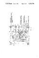
- FIG. 1 is a schematic diagram of a temperature conditioning system incorporatng the subject supply air tempering control.
- FIG. 2 is a block diagram of the microprocessor based control used to control temperature conditioning system of FIG. 1.
- FIG. 3 flow chart illustrating the control logic for supply air tempering when the system is operating in a heating mode.
- FIG. 4 is a flow chart illustrating the control logic for supply air tempering when the system is operating in a cooling mode.
- Temperature conditioning system 10 is a multi-stage system installed as a rooftop unit for temperature conditioning a comfort zone 11.
- System 10 comprises a first two-stage compressor 12 and a second two-stage compressor 13; either compressor 12 or 13 may be selectively energized, with one or both stages of each compressor operative in a cooling mode to meet a temperature conditioning demand.
- four stages of cooling are available.
- Temperature conditioning system 10 may also be selectively operated in a heating mode; the mode is determined by the relative magnitude of the temperature in zone 11 and the heating and cooling setpoints for the zone.
- refrigerant discharged by compressor 12 and 13 flows through refrigerant lines 17 to condenser 18.
- condenser 18 As the compressed refrigerant flows through condenser 18, it is placed in heat transfer relationship with cooler outdoor ambient air, thereby causing the compressed refrigerant to be condensed to a liquid.
- the liquid refrigerant flows through refrigerant lines 19 to evaporator 20, passing through an expansion device (not shown) along the way.
- the refrigerant is vaporized as it expands in evaporator 10, thus cooling the air flowing into the comfort zone 11.
- Refrigerant vapor returns through lines 21 to the suction side of compressors 12 and 13.
- each of four resistance heating elements 14 may be selectively energized to heat air flowing through evaporator 10 (which is then inactive as a heat exchanger). The air is heated as it passes over the heating elements 14 and into zone 11. Alternatively, heat might also be provided by a fossil fuel burner (not shown) having a plurality of stages. Electric resistance heating is shown in FIG. 1 as best illustrating the application of the invention to a multi-stage system. Temperature conditioning system 10 thus functions in a conventional manner to selectively heat or cool air supplied to comfort zone 11.
- fan 23 driven by motor 24 pulls air through the condenser 18 and expels it through the top of the unit.
- air is circulated through evaporator 20 and into comfort zone 11 by means of centrifugal fan 25 driven by electric motor 26.
- An economizer damper 27 with actuator 28 is included to modulate the flow of fresh outdoor air into system 10 from a minimum flow level sufficient to meet building ventilation requirements, to a full flow condition.
- the economizer permits low cost cooling of zone 11 by proportional use of outdoor ambient air when its temperature and humidity are within acceptable limits, as determined by outdoor ambient air temperature and humidity sensors (not shown). Air entering through economizer damper 27 mixes with return air coming from zone 11 through return air duct 29, and is discharged into zone 11 through supply air plenum 30.
- a control box mounted within the enclosure of temperature conditioning system 10 is indicated by reference numeral 35.
- a temperature sensor and means for establishing a zone setpoint 36 is mounted in zone 11.
- the setpoint means comprises an analog variable resistance control.
- the setpoint can also be input from an optional digital keypad/display 34 disposed in the zone, or from a building automation system that may include a separate external computer and keyboard.
- Electrical leads 37 connect the zone sensor/setpoint means 36 with control 35.
- a temperature sensor 15 is exposed to the supply airstream, mounted in the supply air duct 30. Sensor 15 is connected to control 35 by means of leads 16. Alternatively, an average supply air temperature may be determined using a plurality of temperature sensors such as sensor 15.
- Control leads 38a through f connect the control 35 to each of the operating components in temperature conditioning system 10, including compressors 12 and 13, indoor fan motor 26, economizer actuator 28, outdoor fan motor 24, and heating elements 14, respectively.
- Leads 38 represent control lines for actuating relays or contactors (not shown) capable of handling the supply current to each of these components. These leads also include conductors that carry signals for indicating contactor operation, using auxiliary switches provided in the contactors. Details of the contactor mechanism and auxiliary switches are not shown since they are well known to those skilled in the art.
- FIG. 2 a block diagram of the elements comprising the preferred embodiment of control 35 shows that it includes three microprocessors. Each microprocessor has a separate function, however it would also be possible to combine all control functions into a single microprocessor, given sufficient memory.
- Microprocessor 40 handles communications and operates as a master control over microprocessors 41 and 42.
- Processor 41 is labeled as a control processor since it functions to control the stages of temperature conditioning according to the control logic of the subject invention.
- Processor 42 is used for handling input and output of signals relative to the active elements of temperature conditioning system 10 via control leads 38. It also receives signals from the auxiliary switches in the contactors energized by control 35.
- Communications processor 40 is considered the master in the control scheme, since it is responsible for communication between the other two processors 41 and 42 and with an external building automation system computer (not shown).
- the external computer is interfaced to communications processor 40 through a frequency shift keying communication module 45, and a transformer 46 which provides both isolation and impedance matching to a data transmission line.
- the frequency shift keying communications module 45 in combination with processor 40 modulates digital data supplied from the control 35 using two substantially different carrier frequencies to represent binary 1's and 0's, and demodulates data from the external computer received at those two frequencies.
- a three conductor connection 47 between communications module 45 and microprocessor 40 serves to convey these signals bidirectionally.
- Leads 48 also provide a means for inputting an address from a digi-switch (not shown) or from jumpers that may be set (or cut) to identify a particular control 35, assuming that other devices are connected to the external computer via the data transmission line.
- Microprocessor 40 is also connected by leads 49 to a display driver 50, which in turn is connected via leads 37 to display 51, co-located with zone sensor/setpoint means 36.
- a power-on reset module 53 is connected via leads 54 to communication processor 40 and to each of the processors 41 and 42. The purpose of the reset module 53 is to initialize the processors 40-42 whenever power is first applied to control 35.
- Analog inputs including the input from zone temperature sensor 36 on leads 37 and from the supply air temperature sensor 15 on leads 16, are connected to an analog multiplexor 61.
- Multiplexor 61 responds to an input select signal coming from control processor 41 via leads 62. This signal causes the analog multiplexor 61 to pass a selected analog input via leads 63a.
- the selected analog input signal on leads 63a is connected to a non-inverting input on comparator 64 for comparison to a voltage applied via leads 63b to the inverting input of comparator 64; this comparison voltage on leads 63b is derived from a resistance ladder network 65.
- the voltage on leads 63b is controlled by signals output from control processor 41 over leads 68.
- control processor 41 selects a successively lower comparison voltage for input to comparator 64 by closing switches on resistor ladder network 65 until the output from comparator 64 indicates that the voltage level on input 63b is approximately equal to the voltage on the select analog input 63a.
- This technique for analog-to-digital conversion is well known to those skilled in the art as the R-2R conversion scheme, because of the relative magnitude of resistance values used in the ladder circuit.
- Sensors 36 and 15 typically comprise thermistors having a resistance proportional to the zone temperature and supply air temperatures, respectively. Assuming that control processor 41 has selected the analog input from the zone temperature sensor 36, it is thus able to determine the voltage drop across the sensor. By reference to the digital signal applied to resistor ladder 65 via control lines 68 and 66, processor 41 determines the digital equivalent for the analog voltage level that is proportional to the temperature in zone 11. A similar method is used to determine a digital value for the supply air temperature.
- Microprocessor 40 through 42 communicate control signals bi-directionally over control leads 55, and pass data bi-directionally over data lines 66. This permits information that is available to any one of the microprocessors to be accessed by either of the other two. For example, each of the analog inputs reaching the multiplexor 61, when selected by control processor 41 and converted to a digital level, can be output to an external computer through communications processor 40 and FSK communication module 45. Likewise, if an external computer is used to enter data such as a zone setpoint temperature, that data can be made available to the control processor 41 by the communications processor 40. Digital display 52 can be used by the operator to read the zone temperature setpoint, the zone temperature, and other variables available to the control 35 and is located either on optional keypad setpoint means 34 or directly on control 35.
- signals passing over control lines 55 cause the input/output processor 42 to act on the data present on data lines 56, and to produce a corresponding logic level signal on lines 70.
- Lines 70 control relay drivers 71, the outputs of which are connected via leads 72 to the relays 73. Operation of relays 73 cause the contactors for the appropriate elements in the temperature conditioning system 10 to be energized or de-energized accordingly.
- the I/O processor 42 determines if a specific contactor has been actuated by feeding an input select signal over line 78 to multiplexor 80.
- the output from multiplexor 80 comprises the signal from the selected contactor auxiliary switch input to multiplexor 80 via leads 81.
- the economizer actuator 28 is driven via logic level signals on lines 75 connected to an economizer drive 76.
- the higher current levels required by the economizer actuator 28 are sourced by economizer driver 75 and supplied over lines 77 to the actuator 28.
- processors 40 through 42 are determined by a machine language program stored in internal read only memory (ROM) within each processor.
- ROM read only memory
- all three microprocessors are NEC Model 8049 integrated circuits and each includes 2K bytes of internal memory (ROM). These microprocessors also each include 128 bytes of random access memory (RAM).
- RAM random access memory
- Responsibility for energizing and de-energizing stages of temperature conditioning resides in programs stored in the ROM of control processor 41.
- Other functions performed by control 35 are also stored as programs in the ROM of processor 41, and it is by distributing the responsibility for communications and input/output to processors 40 and 42, that control processor 41 is freed to perform these other functions.
- the control functions and algorithms of the subject invention may also be carried out in a single microprocessor or by using other combinations of microprocessors with similar characteristics.
- the cooling mode of system 10 that is provided by operation of compressors 12 and 13 (or by cool outdoor ambient air entering the unit through economizer damper 27), and the heating mode provided by operation of electric heaters 14 is controlled in response to the comfort zone temperature.
- a machine language program stored in the ROM of microprocessor 41 implements a primary algorithm to control the heating and cooling stages to meet a temperature conditioning demand, in response both to the deviation of the zone 11 temperature from the heating or cooling setpoint and to the rate of change of the zone temperature.
- the details of this primary control algorithm are disclosed within the specification of commonly assigned U.S. patent application, Ser. No. 06/557,983, which is specifically incorporated herein by reference.
- the control of temperature conditioning 10 is not limited to the primary algorithm defined in the application referenced above; any staging control that responds to the deviation of the zone temperature from a setpoint is equally applicable as a primary control means within the scope of the subject invention as claimed.
- FIG. 3 the control logic for implementing supply air tempering when system 10 is operating in the heating mode is illustrated with a flow chart. Abreviations used in the flow chart are as follows:
- TZN Comfort Zone Temperature
- TSA Temperature of Supply Air
- control logic determines if TZN is more than 1.2° F. below the heating setpoint temperature THS, and if so, assigns a 0 value to the supply air tempering flag.
- the SAT flag is a binary indicator that shows whether or not a system is operating under the control of the supply air temperature algorithm. When SAT equals 0, supply air tempering is not permitted, and the heating stages are controlled according to the normal or primary algorithm to satisfy the comfort zone heating demand.
- program logic determines if there has been a change in staging and, if not, control 35 drives the damper actuator 28 to close the economizer damper 27 to its minimum position before exiting the routine.
- a supply air tempering timer is restarted to initialize a two-minute delay period during which heating stages may not be energized or de-energized to satisfy the requirement for supply air tempering. Thereafter, program logic again reaches the point of causing the economizer damper 27 to close to its minimum position before exiting the routine.
- the supply air tempering timer comprises an internal counter in control microprocessor 41 that counts clock cycles derived from clock 44 until a predefined count indicates an interval of time has elapsed.
- control logic determines if the zone temperature is 4° F. or more greater than the heating setpoint. This indicates a condition in which supply air tempering would cause too great a temperature rise in the zone and therefore should not be allowed. Consequently, if this condition exists, the control proceeds along the same logic path to enable the primary heat control algorithm as previously discussed. On the other hand, if TZN is not greater than or equal to THS+4°, there is a further check to determine if the supply air temperature is more than 10° below the heating setpoint.
- program logic checks to determine if the SAT flag has been set to 1, and if not, proceeds with the normal primary heating control algorithm.
- a further series of conditions are checked to see if a stage of heating should be de-energized. These conditions include a determination of whether the supply air temperature is greater than 75° F.; a determination of whether the supply air temperature exceeds an economizer setpoint (explained hereinbelow); and a check of whether the supply air temperature is more than 10° above the heating setpoint temperature.
- An affirmative answer to any one of these conditions causes control 35 to de-energize a stage of heating if more than two minutes have elapsed since the last change and more than one stage of heating has been previously energized.
- the economizer setpoint temperature is a setpoint compared to the temperature in the zone to determine if control 35 should cause the heating mode to be terminated, and outdoor ambient air flow through the economizer dampers 27 increased to provide cooling in zone 11.
- the value of TES is usually set several degrees above the heating setpoint temperature. Should the supply air temperature significantly exceed the economizer setpoint due to supply air tempering, system 10 might leave the heating mode even though the zone temperature would indicate a need to remain in the heating mode. For the same reason, the last stage of heating that is energized cannot be de-energized by the secondary control means provided for supply air tempering; only the primary control algorithm can de-energize the last stage of heating that remains on.
- FIG. 4 A flow chart illustrating the control logic for supply air tempering while system 10 is operating in the cooling mode is shown in FIG. 4.
- the abbreviations used in this flow chart are as follows:
- TSA The Temperature of Supply Air
- control blocks is defined in the above referenced patent application, as a plurality of predetermined ranges for the deviation of the zone temperature from the setpoint, with associated limits for the rate of temperature change that determine a specific change in staging. If a new control block range has been entered, a 1 is assigned to the CB flag. This insures an affirmative response to the next program inquiry, to determine if the CB flag equals 1. Further, if a new control block had not been entered, the program also checks the status of the CB flag.
- the program logic thereafter checks the condition of the cool timer to determine if more than three minutes has elapsed.
- the cool timer is a counter incorporated in microprocessor 41 and uses the time base frequency from clock 40 as previously described for the SAT timer. Assuming that more than three minutes have elapsed since the last change in cooling staging, the program determines if the LST flag is equal to 1, and if so, de-energizes one stage of cooling. The number of stages of cooling that are energized is thus decreased by one stage in the condition wherein the LST flag indicates that the supply air temperature is less than the 45° F. and that the economizer damper 27 is at its minimum position.
- the occurrence of these two conditions causes a 1 to be assigned to the LST flag.
- the LST flag has a value of 0, and program logic permits the primary control algorithm for cooling to control the operation of the cooling stages.
- a stage of cooling is de-energized either by the primary control algorithm or as a result of supply air tempering, the cool timer is restarted. If the stage was de-energized as a result of supply air tempering, as indicated by the condition of the LST flag, a value of 1 is assigned to the CB flag; otherwise, a value of 0 is assigned.
- the primary control algorithm adjusts the position of the economizer damper 27 as a function of the comfort zone temperature assuming that the humidity and temperature of the outdoor ambient air within acceptable limits. However, if the supply air temperature is less than or equal to 50° F., program logic does not permit economizer damper 27 to open further. Should the supply air temperature exceed 50° F., the damper is permitted to move to the position determined by the primary control algorithm, before exiting the routine.
- the affect of the preceding program logic is to prevent an increase in the use of cold outdoor ambient air for cooling zone 11 if the supply air temperature is already less than or equal to 50° F.
- the economizer damper 27 is allowed to close further if required by the primary control algorithm.
- the subject invention avoids chilling personnel in comfort zone 11 as a result of uncomfortably cold air from temperature conditioning system 10 being discharged into the zone. It should be apparent, however, that the secondary control algorithm is only allowed to override the primary control if certain conditions are met which tend to guarantee that supply air tempering does not unduly raise the comfort zone temperature above the setpoint.
Abstract
Description
Claims (25)
Priority Applications (2)
| Application Number | Priority Date | Filing Date | Title |
|---|---|---|---|
| US06/621,298 US4543796A (en) | 1984-06-15 | 1984-06-15 | Control and method for tempering supply air |
| CA000478936A CA1228138A (en) | 1984-06-15 | 1985-04-11 | Control and method for tempering supply air |
Applications Claiming Priority (1)
| Application Number | Priority Date | Filing Date | Title |
|---|---|---|---|
| US06/621,298 US4543796A (en) | 1984-06-15 | 1984-06-15 | Control and method for tempering supply air |
Publications (1)
| Publication Number | Publication Date |
|---|---|
| US4543796A true US4543796A (en) | 1985-10-01 |
Family
ID=24489591
Family Applications (1)
| Application Number | Title | Priority Date | Filing Date |
|---|---|---|---|
| US06/621,298 Expired - Lifetime US4543796A (en) | 1984-06-15 | 1984-06-15 | Control and method for tempering supply air |
Country Status (2)
| Country | Link |
|---|---|
| US (1) | US4543796A (en) |
| CA (1) | CA1228138A (en) |
Cited By (21)
| Publication number | Priority date | Publication date | Assignee | Title |
|---|---|---|---|---|
| US4649709A (en) * | 1984-04-13 | 1987-03-17 | Hitachi, Ltd. | Temperature control method and apparatus for air conditioner |
| US4711394A (en) * | 1987-02-26 | 1987-12-08 | Samuel Glenn W | Multiple-unit HVAC energy management system |
| EP0248380A2 (en) * | 1986-06-02 | 1987-12-09 | Johnson Service Company | Apparatus for controlling a variable air volume unit |
| GB2202063A (en) * | 1987-03-10 | 1988-09-14 | Matsushita Electric Ind Co Ltd | Digital air conditioner control |
| US4916913A (en) * | 1987-09-10 | 1990-04-17 | Kabushiki Kaisha Toshiba | Air conditioning apparatus having two refrigerating circuits in central unit and control method of defrosting the same |
| EP0466431A1 (en) * | 1990-07-06 | 1992-01-15 | Mitsubishi Denki Kabushiki Kaisha | Air conditioner controller |
| US5205130A (en) * | 1991-07-02 | 1993-04-27 | Pannell Bobby L | Dual stage AC system for recreational vehicle |
| US5307645A (en) * | 1991-07-02 | 1994-05-03 | Pannell Bobby L | Air conditioning system for a recreational vehicle |
| US5332028A (en) * | 1993-03-12 | 1994-07-26 | Carrier Corporation | Method and apparatus for controlling supplemental electric heat during heat pump defrost |
| US5709100A (en) * | 1996-08-29 | 1998-01-20 | Liebert Corporation | Air conditioning for communications stations |
| US20070227721A1 (en) * | 2001-03-12 | 2007-10-04 | Davis Energy Group, Inc. | System and method for pre-cooling of buildings |
| US7398821B2 (en) * | 2001-03-12 | 2008-07-15 | Davis Energy Group | Integrated ventilation cooling system |
| US20110264275A1 (en) * | 2010-04-21 | 2011-10-27 | Honeywell International Inc. | Demand control ventilation system with commissioning and checkout sequence control |
| KR101286104B1 (en) * | 2012-10-19 | 2013-08-02 | 헵시바주식회사 | Air condition system for booth |
| US8918218B2 (en) | 2010-04-21 | 2014-12-23 | Honeywell International Inc. | Demand control ventilation system with remote monitoring |
| US20150168000A1 (en) * | 2013-12-17 | 2015-06-18 | Ian Robert Dempster | Systems and methods for using a smart valve to control conditioned air |
| US9500382B2 (en) | 2010-04-21 | 2016-11-22 | Honeywell International Inc. | Automatic calibration of a demand control ventilation system |
| US9703299B2 (en) | 2010-09-24 | 2017-07-11 | Honeywell International Inc. | Economizer controller plug and play system recognition with automatic user interface population |
| US20170248340A1 (en) * | 2012-11-09 | 2017-08-31 | Trane International Inc. | Methods of controlling fan capacity and coil capacity in hvac systems |
| US9845963B2 (en) | 2014-10-31 | 2017-12-19 | Honeywell International Inc. | Economizer having damper modulation |
| US10060642B2 (en) | 2014-10-22 | 2018-08-28 | Honeywell International Inc. | Damper fault detection |
Citations (3)
| Publication number | Priority date | Publication date | Assignee | Title |
|---|---|---|---|---|
| US4384462A (en) * | 1980-11-20 | 1983-05-24 | Friedrich Air Conditioning & Refrigeration Co. | Multiple compressor refrigeration system and controller thereof |
| US4408713A (en) * | 1980-11-04 | 1983-10-11 | Nissan Motor Co., Ltd. | Control for automobile air conditioning system |
| US4471632A (en) * | 1981-09-09 | 1984-09-18 | Nippondenso Co., Ltd. | Method of controlling refrigeration system for automotive air conditioner |
-
1984
- 1984-06-15 US US06/621,298 patent/US4543796A/en not_active Expired - Lifetime
-
1985
- 1985-04-11 CA CA000478936A patent/CA1228138A/en not_active Expired
Patent Citations (3)
| Publication number | Priority date | Publication date | Assignee | Title |
|---|---|---|---|---|
| US4408713A (en) * | 1980-11-04 | 1983-10-11 | Nissan Motor Co., Ltd. | Control for automobile air conditioning system |
| US4384462A (en) * | 1980-11-20 | 1983-05-24 | Friedrich Air Conditioning & Refrigeration Co. | Multiple compressor refrigeration system and controller thereof |
| US4471632A (en) * | 1981-09-09 | 1984-09-18 | Nippondenso Co., Ltd. | Method of controlling refrigeration system for automotive air conditioner |
Cited By (38)
| Publication number | Priority date | Publication date | Assignee | Title |
|---|---|---|---|---|
| US4649709A (en) * | 1984-04-13 | 1987-03-17 | Hitachi, Ltd. | Temperature control method and apparatus for air conditioner |
| EP0248380A2 (en) * | 1986-06-02 | 1987-12-09 | Johnson Service Company | Apparatus for controlling a variable air volume unit |
| EP0248380A3 (en) * | 1986-06-02 | 1990-01-10 | Johnson Service Company | Apparatus for controlling a variable air volume unit |
| US4711394A (en) * | 1987-02-26 | 1987-12-08 | Samuel Glenn W | Multiple-unit HVAC energy management system |
| GB2202063A (en) * | 1987-03-10 | 1988-09-14 | Matsushita Electric Ind Co Ltd | Digital air conditioner control |
| US5043926A (en) * | 1987-03-10 | 1991-08-27 | Matsushita Electric Industrial Co., Ltd. | Data drive type air conditioner control apparatus |
| GB2202063B (en) * | 1987-03-10 | 1991-10-09 | Matsushita Electric Ind Co Ltd | Data drive type air conditioner control apparatus |
| US4916913A (en) * | 1987-09-10 | 1990-04-17 | Kabushiki Kaisha Toshiba | Air conditioning apparatus having two refrigerating circuits in central unit and control method of defrosting the same |
| EP0466431A1 (en) * | 1990-07-06 | 1992-01-15 | Mitsubishi Denki Kabushiki Kaisha | Air conditioner controller |
| US5205130A (en) * | 1991-07-02 | 1993-04-27 | Pannell Bobby L | Dual stage AC system for recreational vehicle |
| US5307645A (en) * | 1991-07-02 | 1994-05-03 | Pannell Bobby L | Air conditioning system for a recreational vehicle |
| US5332028A (en) * | 1993-03-12 | 1994-07-26 | Carrier Corporation | Method and apparatus for controlling supplemental electric heat during heat pump defrost |
| US5709100A (en) * | 1996-08-29 | 1998-01-20 | Liebert Corporation | Air conditioning for communications stations |
| US20070227721A1 (en) * | 2001-03-12 | 2007-10-04 | Davis Energy Group, Inc. | System and method for pre-cooling of buildings |
| US7398821B2 (en) * | 2001-03-12 | 2008-07-15 | Davis Energy Group | Integrated ventilation cooling system |
| US7992630B2 (en) | 2001-03-12 | 2011-08-09 | Davis Energy Group, Inc. | System and method for pre-cooling of buildings |
| US8918218B2 (en) | 2010-04-21 | 2014-12-23 | Honeywell International Inc. | Demand control ventilation system with remote monitoring |
| US20110264275A1 (en) * | 2010-04-21 | 2011-10-27 | Honeywell International Inc. | Demand control ventilation system with commissioning and checkout sequence control |
| US9255720B2 (en) * | 2010-04-21 | 2016-02-09 | Honeywell International Inc. | Demand control ventilation system with commissioning and checkout sequence control |
| US9500382B2 (en) | 2010-04-21 | 2016-11-22 | Honeywell International Inc. | Automatic calibration of a demand control ventilation system |
| US9765986B2 (en) | 2010-04-21 | 2017-09-19 | Honeywell International Inc. | Demand control ventilation system with commissioning and checkout sequence control |
| US10670288B2 (en) | 2010-04-21 | 2020-06-02 | Honeywell International Inc. | Demand control ventilation system with commissioning and checkout sequence control |
| US10429861B2 (en) | 2010-09-24 | 2019-10-01 | Honeywell International Inc. | Economizer controller plug and play system recognition with automatic user interface population |
| US11334097B2 (en) | 2010-09-24 | 2022-05-17 | Honeywell Internatioanl, Inc. | Economizer controller plug and play system recognition with automatic user interface population |
| US9703299B2 (en) | 2010-09-24 | 2017-07-11 | Honeywell International Inc. | Economizer controller plug and play system recognition with automatic user interface population |
| KR101286104B1 (en) * | 2012-10-19 | 2013-08-02 | 헵시바주식회사 | Air condition system for booth |
| US20170248340A1 (en) * | 2012-11-09 | 2017-08-31 | Trane International Inc. | Methods of controlling fan capacity and coil capacity in hvac systems |
| US10775069B2 (en) | 2012-11-09 | 2020-09-15 | Trane International Inc. | HVAC system and corresponding methods of controlling HVAC fan and coil capacity |
| US10197300B2 (en) * | 2012-11-09 | 2019-02-05 | Trane International Inc. | Methods of controlling fan capacity and coil capacity in HVAC systems |
| US10119711B2 (en) * | 2013-12-17 | 2018-11-06 | Optimum Energy Llc | Air handler unit including a smart valve |
| US10739021B2 (en) | 2013-12-17 | 2020-08-11 | Belimo Holding Ag | Systems and methods for using a smart valve to control conditioned air |
| US20150168000A1 (en) * | 2013-12-17 | 2015-06-18 | Ian Robert Dempster | Systems and methods for using a smart valve to control conditioned air |
| US10060642B2 (en) | 2014-10-22 | 2018-08-28 | Honeywell International Inc. | Damper fault detection |
| US11054161B2 (en) | 2014-10-22 | 2021-07-06 | Honeywell International Inc. | Damper fault detection |
| US11635222B2 (en) | 2014-10-22 | 2023-04-25 | Honeywell International Inc. | Damper fault detection |
| US10690362B2 (en) | 2014-10-31 | 2020-06-23 | Honeywell International, Inc. | Economizer having damper modulation |
| US9845963B2 (en) | 2014-10-31 | 2017-12-19 | Honeywell International Inc. | Economizer having damper modulation |
| US10935264B2 (en) | 2014-10-31 | 2021-03-02 | Honeywell International Inc. | Economizer having damper modulation |
Also Published As
| Publication number | Publication date |
|---|---|
| CA1228138A (en) | 1987-10-13 |
Similar Documents
| Publication | Publication Date | Title |
|---|---|---|
| US4543796A (en) | Control and method for tempering supply air | |
| US4501125A (en) | Temperature conditioning system staging control and method | |
| US4353409A (en) | Apparatus and method for controlling a variable air volume temperature conditioning system | |
| US5172565A (en) | Air handling system utilizing direct expansion cooling | |
| US4389853A (en) | Method and apparatus for controlling an air conditioning unit with multi-speed fan and economizer | |
| CA1164970A (en) | Microprocessor discharge temperature air controller for multi-stage heating and/or cooling apparatus and outdoor air usage controller | |
| US4270362A (en) | Control system for an air conditioning system having supplementary, ambient derived cooling | |
| EP0097607B1 (en) | Variable volume multizone unit | |
| US5860473A (en) | Multi-zone automatic changeover heating, cooling and ventilating control system | |
| US4379484A (en) | Control for a variable air volume temperature conditioning system-outdoor air economizer | |
| US4253153A (en) | Energy conservative control of terminal reheat heating, ventilating, and air conditioning (HVAC) systems | |
| US5979167A (en) | Central air conditioning system | |
| US5488218A (en) | Electric heat control apparatus and method | |
| EP0498645B1 (en) | A control apparatus for an air conditioner | |
| US20070057075A1 (en) | System and method for heat pump oriented zone control | |
| US3930611A (en) | Air conditioning control system and method | |
| WO1997035154A1 (en) | Variable air volume hvac system controller | |
| US4404815A (en) | Air conditioning economizer control method and apparatus | |
| US5131236A (en) | Air handling system utilizing direct expansion cooling | |
| US6176306B1 (en) | Method and device for controlling operation of heat pump | |
| US5170635A (en) | Defrost for air handling system utilizing direct expansion cooling | |
| CA1172338A (en) | Transport and chiller energy minimization for air conditioning systems | |
| US20050087616A1 (en) | Thermal balance temperature control system | |
| US5138842A (en) | Air handling system utilizing direct expansion cooling | |
| US4633937A (en) | Method and apparatus for multi-zone air distribution system |
Legal Events
| Date | Code | Title | Description |
|---|---|---|---|
| AS | Assignment |
Owner name: TRANE COMPANY THE, A CORP OF DE Free format text: ASSIGNMENT OF ASSIGNORS INTEREST.;ASSIGNORS:HAN, DOYOUNG;HANSEN, WILLIAM G.;REEL/FRAME:004277/0018 Effective date: 19840613 |
|
| AS | Assignment |
Owner name: AMERICAN STANDARD INC., A CORP OF DE Free format text: MERGER;ASSIGNORS:TRANE COMPANY, THE;A-S SALEM INC., A CORP. OF DE (MERGED INTO);REEL/FRAME:004372/0349 Effective date: 19841226 |
|
| AS | Assignment |
Owner name: A-S CAPITAL INC., A CORP OF DE Free format text: MERGER;ASSIGNOR:TRANE COMPANY THE A WI CORP;REEL/FRAME:004432/0765 Effective date: 19840224 |
|
| STCF | Information on status: patent grant |
Free format text: PATENTED CASE |
|
| AS | Assignment |
Owner name: A-S CAPITAL INC. Free format text: MERGER;ASSIGNOR:TRANE COMPANY THE;REEL/FRAME:004476/0376 Effective date: 19840224 |
|
| AS | Assignment |
Owner name: BANKERS TRUST COMPANY Free format text: SECURITY INTEREST;ASSIGNOR:AMERICAN STANDARD INC., A DE. CORP.,;REEL/FRAME:004905/0035 Effective date: 19880624 Owner name: BANKERS TRUST COMPANY, 4 ALBANY STREET, 9TH FLOOR, Free format text: SECURITY INTEREST;ASSIGNOR:TRANE AIR CONDITIONING COMPANY, A DE CORP.;REEL/FRAME:004905/0213 Effective date: 19880624 Owner name: BANKERS TRUST COMPANY, NEW YORK Free format text: SECURITY INTEREST;ASSIGNOR:TRANE AIR CONDITIONING COMPANY, A DE CORP.;REEL/FRAME:004905/0213 Effective date: 19880624 |
|
| FPAY | Fee payment |
Year of fee payment: 4 |
|
| FPAY | Fee payment |
Year of fee payment: 8 |
|
| AS | Assignment |
Owner name: CHEMICAL BANK, AS COLLATERAL AGENT, NEW YORK Free format text: ASSIGNMENT OF ASSIGNORS INTEREST;ASSIGNOR:AMERICAN STANDARD INC.;REEL/FRAME:006566/0170 Effective date: 19930601 Owner name: CHEMICAL BANK, AS COLLATERAL AGENT, NEW YORK Free format text: ASSIGNMENT OF SECURITY INTEREST;ASSIGNOR:BANKERS TRUST COMPANY, AS COLLATERAL TRUSTEE;REEL/FRAME:006565/0753 Effective date: 19930601 |
|
| FPAY | Fee payment |
Year of fee payment: 12 |
|
| AS | Assignment |
Owner name: AMERICAN STANDARD, INC., NEW JERSEY Free format text: RELEASE OF SECURITY INTEREST (RE-RECORD TO CORRECT DUPLICATES SUBMITTED BY CUSTOMER. THE NEW SCHEDULE CHANGES THE TOTAL NUMBER OF PROPERTY NUMBERS INVOLVED FROM 1133 TO 794. THIS RELEASE OF SECURITY INTEREST WAS PREVIOUSLY RECORDED AT REEL 8869, FRAME 0001.);ASSIGNOR:CHASE MANHATTAN BANK, THE (FORMERLY KNOWN AS CHEMICAL BANK);REEL/FRAME:009123/0300 Effective date: 19970801 |
|
| AS | Assignment |
Owner name: AMERICAN STANDARD, INC., NEW JERSEY Free format text: RELEASE OF SECURITY INTEREST;ASSIGNOR:CHASE MANHATTAN BANK, THE (FORMERLY KNOWN AS CHEMICAL BANK);REEL/FRAME:008869/0001 Effective date: 19970801 |
|
| AS | Assignment |
Owner name: AMERICAN STANDARD INTERNATIONAL INC., NEW YORK Free format text: NOTICE OF ASSIGNMENT;ASSIGNOR:AMERICAN STANDARD INC., A CORPORATION OF DELAWARE;REEL/FRAME:011474/0650 Effective date: 20010104 |