US4461576A - Optical measuring system - Google Patents
Optical measuring system Download PDFInfo
- Publication number
- US4461576A US4461576A US06/235,400 US23540081A US4461576A US 4461576 A US4461576 A US 4461576A US 23540081 A US23540081 A US 23540081A US 4461576 A US4461576 A US 4461576A
- Authority
- US
- United States
- Prior art keywords
- mirror
- light
- workpiece
- plane mirror
- parabolic
- Prior art date
- Legal status (The legal status is an assumption and is not a legal conclusion. Google has not performed a legal analysis and makes no representation as to the accuracy of the status listed.)
- Expired - Lifetime
Links
- 230000003287 optical effect Effects 0.000 title claims abstract description 25
- 239000007788 liquid Substances 0.000 claims abstract description 15
- 238000000034 method Methods 0.000 claims abstract description 14
- 230000008569 process Effects 0.000 claims abstract description 14
- 239000006060 molten glass Substances 0.000 claims abstract description 5
- 239000000463 material Substances 0.000 claims description 28
- 230000001419 dependent effect Effects 0.000 claims description 12
- 238000005259 measurement Methods 0.000 claims description 11
- 238000012545 processing Methods 0.000 claims description 11
- 230000000977 initiatory effect Effects 0.000 claims description 5
- 230000004044 response Effects 0.000 claims description 5
- 239000000523 sample Substances 0.000 claims 5
- 238000005070 sampling Methods 0.000 claims 5
- 230000009969 flowable effect Effects 0.000 claims 1
- 239000013074 reference sample Substances 0.000 claims 1
- 238000010586 diagram Methods 0.000 description 5
- 230000004913 activation Effects 0.000 description 4
- 238000001994 activation Methods 0.000 description 4
- 230000001360 synchronised effect Effects 0.000 description 3
- 230000008859 change Effects 0.000 description 2
- 239000011521 glass Substances 0.000 description 2
- 239000012768 molten material Substances 0.000 description 2
- 230000003321 amplification Effects 0.000 description 1
- 230000001427 coherent effect Effects 0.000 description 1
- 230000000052 comparative effect Effects 0.000 description 1
- 238000010276 construction Methods 0.000 description 1
- 238000009749 continuous casting Methods 0.000 description 1
- 238000001816 cooling Methods 0.000 description 1
- 239000000498 cooling water Substances 0.000 description 1
- 230000009849 deactivation Effects 0.000 description 1
- 238000013461 design Methods 0.000 description 1
- 230000007257 malfunction Effects 0.000 description 1
- 230000007246 mechanism Effects 0.000 description 1
- 229910052751 metal Inorganic materials 0.000 description 1
- 239000002184 metal Substances 0.000 description 1
- 150000002739 metals Chemical class 0.000 description 1
- 238000012544 monitoring process Methods 0.000 description 1
- 238000003199 nucleic acid amplification method Methods 0.000 description 1
- 230000005855 radiation Effects 0.000 description 1
Images


Classifications
-
- G—PHYSICS
- G01—MEASURING; TESTING
- G01F—MEASURING VOLUME, VOLUME FLOW, MASS FLOW OR LIQUID LEVEL; METERING BY VOLUME
- G01F23/00—Indicating or measuring liquid level or level of fluent solid material, e.g. indicating in terms of volume or indicating by means of an alarm
- G01F23/22—Indicating or measuring liquid level or level of fluent solid material, e.g. indicating in terms of volume or indicating by means of an alarm by measuring physical variables, other than linear dimensions, pressure or weight, dependent on the level to be measured, e.g. by difference of heat transfer of steam or water
- G01F23/28—Indicating or measuring liquid level or level of fluent solid material, e.g. indicating in terms of volume or indicating by means of an alarm by measuring physical variables, other than linear dimensions, pressure or weight, dependent on the level to be measured, e.g. by difference of heat transfer of steam or water by measuring the variations of parameters of electromagnetic or acoustic waves applied directly to the liquid or fluent solid material
- G01F23/284—Electromagnetic waves
- G01F23/292—Light, e.g. infrared or ultraviolet
-
- G—PHYSICS
- G01—MEASURING; TESTING
- G01B—MEASURING LENGTH, THICKNESS OR SIMILAR LINEAR DIMENSIONS; MEASURING ANGLES; MEASURING AREAS; MEASURING IRREGULARITIES OF SURFACES OR CONTOURS
- G01B11/00—Measuring arrangements characterised by the use of optical techniques
- G01B11/02—Measuring arrangements characterised by the use of optical techniques for measuring length, width or thickness
Definitions
- the present invention relates to optical measuring devices, and more specifically to gauges utilizing a scanned light beam to measure a linear dimension of a workpiece, or the linear distance from a reference point to a point on the workpiece upon which the beam is directed.
- Optical gauges are employed in many applications, among which are those where mechanical contact is undesirable or impossible, and those where optical measurement is more rapid and/or reliable than mechanical. For example, in processing molten glass and continuous casting of metals it is necessary to maintain the surface level of the material between desired limits as the process continues. Optical gauges wherein only a light beam contacts the process material are the natural choice for such applications. Lasers provide a desirable light source for optical gauges of this type since they emit a concentrated beam of coherent radiation at a wavelength selected for best performance in the particular environment in which the gauge is to be employed.
- the principal object of the invention in a general sense, is to provide novel and improved apparatus for measuring a linear dimension with superior accuracy and reliability without physical contact with the object or material being measured.
- Another object is to provide a gauge which continuously monitors the vertical level of molten materials or other process liquids and which may be installed and calibrated without shutting down the process.
- a further object is to provide optical measuring apparatus of improved accuracy and reliability for making continuous and rapid measure--of the height, width, thickness, diameter, etc. of a workpiece.
- Still another object is to provide optical apparatus for measuring linear distances wherein an electronically measured time period is directly commensurate with the dimension being measured.
- the invention contemplates an optical measuring device employing a laser light source, a stationary parabolic mirror, a rotating plane mirror, a photo-detector and an electronics package for establishing a time period in response to actuation of the photo-detector & converting the time period to the desired measurement, with which it is directly commensurate.
- the beam may strike the parabolic and plane mirrors and the object or material being measured in any desired order, but in any event the axis of rotation of the plane mirror intersects the optical axis of the parabolic mirror at the latter's focal point.
- the rotating mirror is carried on the output shaft of a synchronous motor which also carries an opaque disc having a slot or cut-out area therein.
- a light source and a photo-diode are fixedly positioned on opposite sides of the disc so that the cut-out portion of the disc passes therebetween during a fixed portion of each revolution of the motor.
- the photo-sensitive device upon which the laser beam ultimately impinges will be referred to herein as "photo-detector" and the device which is activated by the fixed light source and which is located on the opposite side of the opaque disc as a "photo-diode".
- the laser beam is reflected from the surface of the workpiece and in the second disclosed embodiment of the beam is occluded by the workpiece during a portion of each revolution of the mirror.
- the photo-diode is used simply to provide a signal for initiating each cycle while the time period commensurate with the measured dimension is the period between two activations (or deactivations) of the photo-detector which occur during each scan due to the position of the workpiece, as will later become apparent.
- the invention is disclosed in a configuration as employed to measure the surface level of molten glass relative to a reference plane.
- a laser source is positioned to project a beam at a known angle upon the surface of the glass for reflection thereby to a parabolic mirror.
- the beam will strike the parabolic mirror at different points along a radial path thereon. From the parabolic mirror the beam is reflected to a point on the rotational axis of a rotating plane mirror(at the focal point of the parabolic mirror) and thence in a moving path which intersects the photo-detector during a portion of its travel.
- the angular position of the plane mirror at the time the beam intersects the photo-detector varies.
- the time between activation of the photodiode and of the photo-detector varies, providing a direct indication of the distance between actual surface level and a predetermined norm, or reference surface.
- the laser is mounted on one side of the work and the optics (mirrors, lenses and filters) and detector unit are in a separate housing on the other side.
- the elements are shown in a configuration as employed to measure the outside diameter of a workpiece.
- the laser beam is projected along a first axis from which it is reflected at 90° by a fixed plane mirror to the rotating mirror which scans the beam diametrically across the parabolic mirror; the laser, fixed and rotating plane mirrors and parabolic mirror are all housed in a common enclosure on one side of the workpiece.
- the scanned beam reflected by the parabolic mirror moves linearly in a direction perpendicular to its axis.
- a second fixed, parabolic mirror is employed, positioned in a separate housing, facing the first parabolic mirror and coaxial therewith.
- the beam reflected from the first parabolic mirror is thus scanned diametrically across the second parabolic mirror and reflected thereby to the photo-detector, positioned at its focal point.
- the object being measured is placed in the path of the scanned beam between the two parabolic mirrors and occludes the beam during a portion of its scan.
- the beam impinges on the photo-detector both immediately before and immediately after being blocked by the work, the time period during which the beam is blocked being a direct indication of the object's outside diameter (or width).
- the arrangement of the optical elements employed provides measurements free from possible errors due to misalignment of the workpiece with the gauge and other factors present in gauges in which the beam is reflected directly from a scanning mirror to a photo-detector.
- FIG. 1 is a diagrammatic illustration of the first embodiment of the invention, shown in use in a typical application;
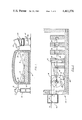
- FIG. 2 is a side elevation view, in section, of a portion of the apparatus shown in FIG. 1;
- FIG. 3 is a plan view of the apparatus of FIG. 2;
- FIG. 4 is a fragmentary, rear elevational view of a portion of the apparatus, taken on line 3--3 of FIG. 3;
- FIG. 5 is a fragmentary, front elevation view taken on the line 5--5 of FIG. 3;
- FIG. 5 is a diagrammatic illustration of certain geometric relationships involved in the invention.
- FIG. 5a is a front elevation view of one of the elements
- FIG. 6 is a timing diagram, i.e., a graphical illustration of ceratin electrical signals with respect to time, as employed in the measurement system of the embodiment of the invention shown in FIGS. 1-5a;
- FIG. 7 is a block diagram of an electronics package suitable for implementing the measurement system of this embodiment.
- FIG. 8 is a perspective view showing the general external appearance of a second embodiment of the invention.
- FIG. 9 is a somewhat diagramic plan view illustrating the operation of the second embodiment of the invention.
- FIG. 10 is a timing diagram of the electrical signals generated and processed to provide the measurements in the embodiment of FIGS. 8 and 9.
- FIG. 1 a light source, preferably a laser, indicated diagrammatically at 10, mounted in a suitable housing on support structure 12 to direct a beam of light along axis A.
- the gauging apparatus of the invention is used to monitor the level of a process material 14, such as molten glass within a refractory chamber 16.
- Axis A passes through opening 18 in a wall of chamber 16 and the beam strikes the surface of material 14 at a predetermined angle ⁇ .
- means are provided on support structure 12 for adjustably positioning light source 10 to establish the angle of incidence of the beam upon the material surface at the desired value.
- the beam After reflection by the surface of material 14 the beam is directed along a second axis having a position dependent upon the vertical level of the material surface.
- the axis of the reflected beam When the surface is at the first level, indicated in solid line at L 1 , the axis of the reflected beam is at B 1 .
- the reflected beam axis When the level is as indicated by dashed line L 2 the reflected beam axis is positioned at B 2 .
- the reflected beam passes through opening 20 in a second wall of chamber 16 and is received by a detector unit indicated generally at 22, enclosed by a second housing positioned on support structure 24 which is affixed to the underlying surface and may include mechanism 26 for adjustably positioning unit 22.
- Detector unit 22 is mounted with its major axis parallel with the axis of the reflected beam; that is, unit 22 is mounted with its axis at the same angle to the process material surface as the axis of light source 10. Since the system may be employed in applications where very high temperatures are common, water jackets or other such cooling means are preferably provided for detector unit 22 as well as light source 10. A passage way for cooling water in the housing of detector 22 is indicated in FIG. 2 at 28.
- Unit 22 includes an entrance aperture 30, elongated in the direction in which the beam axis is displaced as the level of the process material varies.
- the beam is directed upon fixed parabolic mirror 32 and reflected thereby to plane mirror 34 which is mounted on output shaft 36 of synchronous electric motor 38.
- a critical feature of the arrangement of the elements is the positioning of the axis of rotation of motor 38 in the plane of the reflecting surface of mirror 34 and at the focal point of mirror 32. That is, the beam is focused by parabolic mirror 32 upon the surface of plane mirror 34 at the axis of rotation thereof.
- the axis of the beam after reflection by mirror 34 is scanned in an arcuate path about the axis of rotation of the mirror over that portion of its travel during each revolution when the beam strikes the mirror's reflective surface.
- Mirror 32 and its supporting structure are provided with a central aperture 40, the axis C of which is the optical axis of mirror 32 and is parallel to the axis (B 1 , B 2 ) of the beam entering unit 22.
- Additional elements positioned along axis C include an optional double convex lens 42, filter 44, condensing lens 46 and photo-detector 48.
- the scanned beam will be directed along axis C to impinge upon photo-detector 48. The angular position of mirror 34 at which this occurs is dependent upon the point at which the beam strikes mirror 32.
- the reflection of the beam from mirror 34 will be directed along axis C when mirror 34 is at the rotational position indicated in FIG. 2 in solid lines; when the beam is positioned at axis B 2 , the reflection along axis C will occur when mirror 34 is at the rotational position indicated in dotted lines.
- the positions of mirror 34 shown in FIG. 2 are, of course, for comparative purposes only and not intended to be geometrically accurate.
- Output shaft 36 of motor 38 in addition to mirror 34, also carries opaque disc 50 having a cut-out area or opening 52 in a portion thereof.
- Mounting block 54 includes an open slot 56 (FIG. 4) through which the portion of disc 50 wherein opening 52 is located travels as the disc rotates.
- Light source 58 such as a light-emitting diode
- photo-diode 60 are supported in mounting block 54 on opposite sides of slot 56 at a position which is passed by opening 52 as disc 50 rotates.
- opaque disc 50 blocks the passage of light from source 58 to photo-diode 60 except at the time opening 52 is positioned between the two.
- the electrical signal generated by photo-diode 60 during the time opening 52 is aligned therewith provides a reference or index period in each revolution of motor 38 which may operate, for example, at 3,600 rpm.
- the time period which elapses between activation of photo-diode 60 as the leading edge of opening 52 passes light source 58, and activation of photo-detector 48, which occurs at a point in the revolution dependent upon the position of the beam axis entering detector unit 22, is thus directly related to the surface level of the process material by which the beam is reflected.
- the elements are so constructed and arranged that the beam reflected from mirror 34 strikes photo-detector 48 during the index period, while opening 52 is positioned between light source 58 and photo-diode 60, as explained later in more detail.
- the time period may be measured electronically and converted to the desired measurement of surface level, as described in the following paragraphs.
- FIG. 5 illustrates the geometric relationships of the beam and process material surface at the maximum and minimum surface levels which the gauge is designed to monitor.
- the length of axis A between the points at which it strikes the material surface at levels L, and L 2 is denoted "Z” and the distance between axes B 1 and B 2 is denoted "D".
- D the distance between axes B 1 and B 2
- the usable range of the system (dh) may be calculated.
- the dimension D which is a function of the size of the parabolic mirror used, must be known.
- the straight-line horizontal distance between the points at which axis A strikes the process material surface at the upper and lower limits, denoted "X”, may be determined. That is, with D and ⁇ 1 known:
- the dimensional parameter of component design which controls the limits within which the system will operate is the effective or usable radius of the parabolic mirror.
- axis B 1 strikes the surface of mirror 32 at point P 1
- axis B 2 strikes the mirror at point P 2 .
- the geometric center of the parabola lies within opening 40 so the dimension D is somewhat less than the actual radius of the parabola.
- the beam strikes mirror 32 at some point along line R, at or between points P 1 and P 2 .
- the beam may actually be a spot of various size and degree of symmetry as it appears on mirror 32 it will, in any event, be focused to a fine point at the surface of mirror 34.
- axes A, B and C lie in a common vertical plane. Only a segment of the parabola need be provided as mirror 32, as indicated in FIG. 5a, since only one radial portion of its surface is actually utilized. A full parabola, however, may be easier to align and calibrate than a small segment.
- a square wave signal is generated by photo-diode 60 as disc 50 rotates to alternately permit light from source 58 to strike photo-diode 60 during a short portion of each revolution (e.g., about 10°) and to block light during the remainder of the time.
- One such square wave will thus be generated during each revolution of motor 38 and is termed, in FIG. 6, the index signal.
- the time period during each revolution when light strikes photo-diode 60 which in the example shown changes the signal from high to low, is termed the index period. Since the size of opening 52 and its rotational position with respect to motor 38 are fixed, the leading and trailing edges of each square wave of the index signal will vary only as a function of motor speed.
- each index signal is used to activate a reference signal in the form of a ramp voltage, indicated by trace 64, increasing a constant rate within each index period.
- a square wave signal is also generated in response to the beam from source 10, reflected from the surface of material 14, mirrors 32 and 34, impinging upon photo-detector 48 at some point in each revolution depending upon the surface level of material 14.
- the detector or beam signal indicated in FIG. 6 by trace 66, occurs in each cycle when the rotational position of mirror 34 is such that the beam is reflected thereby along axis C which, as previously explained, is dependent upon the position of axis B which, in turn, is dependent upon the level of the surface being monitored. In any case, the detector or beam signal always occurs within the index period.
- the ramp reference signal 64 is integrated from the beginning to the end of each cycle by appropriate circuitry, producing a total integrated value represented by shaded area Y at the end of the cycle. Also, the integrated value is arrested by the leading edge of detector signal 66 and held until the end of the cycle. This is represented as a separate trace 68, termed the level signal since in this example it is commensurate with the surface level being measured. For example, when the beam is reflected from surface L 1 along axis B 1 (FIG. 5) the leading edge of detector signal 66 occurs at a time T 1 of the index period. The integrated value of the ramp voltage at time T 1 is represented by shaded area Z 1 .
- the leaading edge of the detector signal occurs at time to T 2 and the integrated value of the ramp voltage is represented by the sum of shaded areas Z 1 and Z 2 .
- the value of Y will change to reflect any variations in the speed of motor 38, while the value of Z is dependent upon the vertical level of the surface being measured.
- the trailing edge of index signal 62 is used to trigger appropriate control circuitry to read the values of Y and Z, and to reset the reference signal for the next cycle.
- FIG. 7 A block diagram of suitable signal processing means for the functions just described is shown in FIG. 7.
- the signal processing electronics package may be located remotely from the optics and detector and is indicated in FIG. 1 by block 69.
- the signals generated by the index and beam sensors (photo-diode 60 and photo-detector 48, respectively) are each amplified and squared in corresponding circuits 70 and 70'.
- the resulting signals 62 and 66 are each applied to control logic circuit 71 which is responsive to the leading and trailing edges of index and beam signals 62 and 66, respectively.
- Ramp (reference) signal 64 produced by ramp generator 64', is started and reset at the beginning and end, respectively, of each index signal 62 and the level signal 68 is held by sample/hold circuit 68' at the beginning of beam signal 66.
- the integrated values (Y and Z) of the reference and beam signals respectively are divided to provide a ratio (Z/Y) which is stored in ratio sample/hold circuit 73 and, after amplification, an output signal (Z/Y) k, which is directly commensurate with the dimension (level) being measured, is produced.
- the index and beam signals 62 and 66 are also applied to appropriate timer and alarm circuitry which monitors the presence or absence of the signals and provides an alarm indicating a system malfunction, misalignment, etc. if no index and/or beam signal is sensed after a predetermined number (e.g., 15) of cycles.
- FIGS. 8-10 the invention is shown in an embodiment wherein the beam is occluded rather than reflected by the workpiece.
- This embodiment is illustrated as employed to measure the outside diameter of cylindrical objects, but may be used to measure the distance between any two points or an object between or on opposite sides of which the measuring beam is occluded by the object, or to measure the distance from a reference position to a single point on the object, e.g., an edge position.
- the beam source again preferably a laser, and beam scanning optics are enclosed within a first housing 72, while the beam dector and associated electronics package are enclosed in second housing 74.
- Object 76 is positioned between housings 72 and 74.
- the beam from laser 78 is directed upon a fixed, first surface mirror 80 by which it is reflected to plane mirror 82.
- Mirror 82 is carried on the shaft of synchronous electric motor 84, as is opaque disc 86 having opening 88 therein. Operation of the disc in conjunction with a light source and photo diode to establish an index period in each revolution of motor 84 may be identical to that of the previously described embodiment and is therefore not shown again in detail.
- the axis of rotation of mirror 82 intersects the central axis of fixed parabolic mirror 90 at the latter's focal point, upon which the beam reflected by mirror 80 is directed.
- the beam is scanned diametrically across parabolic mirror 90 and reflected thereby through an elongated opening (not shown) in housing 72 and a corresponding opening 92 in housing 74. Since mirror 82 is at the focal point of mirror 90, the beam reflected by the latter always remains parallel to the central axis.
- a second, fixed, parabolic mirror 94 is positioned in housing 74 in facing relation to mirror 90 and on a common central axis.
- Photo-detector 96 is positioned in facing relation to mirror 94 on the central axis and at the focal point thereof. Therefore, the beam which is scanned across mirror 94 in a path parallel to its central axis is focused upon photo-detector 96, except for that portion of the scan where the beam is occluded by object 76, as when the beam is in position F.
- Index signal 98 goes from high to low during the time light passes through opening 88 to establish an index period, just as in the previously described embodiment.
- Reference signal 100 is generated as a ramp voltage during the index period, also as before.
- the laser beam begins scanning across mirrors 90 and 94 to impinge upon photo-detector 96 and change the beam signal 102 from high to low.
- signal 102 again goes high to produce another square wave with leading and trailing edges represented by traces 104 and 106, respectively.
- These signals are used to sample the values of the reference signal (or the integrated value thereof from the beginning of the index period) at the corresponding times.
- the (integrated) value of signal 100 is sampled at the end of each index period and the three values are read, corresponding to the values of signals 108 and 110 at the times sampled.
- Signal 108 is subtracted from signal 110 and the difference is ratioed with signal 100 to provide an output directly commensurate with the dimension being measured. If the position of only one point on the workpiece is to be measured relative to a reference point, the workpiece is positioned to extend into the path of the beam between mirrors 90 and 94.
- the illustrated embodiments both employ parabolic mirrors wherein the focal point lies on the central axis
- the invention also contemplates construction wherein the focal point of the parabolic mirror(s) is not on the central axis.
Abstract
Description
Z=D/Sin 2θ.sub.1
dh=Z Sin θ.sub.1 =Sin θ.sub.1 (D/Sin 2θ.sub.1)
X=Z Cos θ.sub.1 =Cos θ.sub.1 (D/Sin 2θ.sub.1)
Claims (23)
Priority Applications (1)
| Application Number | Priority Date | Filing Date | Title |
|---|---|---|---|
| US06/235,400 US4461576A (en) | 1981-02-18 | 1981-02-18 | Optical measuring system |
Applications Claiming Priority (1)
| Application Number | Priority Date | Filing Date | Title |
|---|---|---|---|
| US06/235,400 US4461576A (en) | 1981-02-18 | 1981-02-18 | Optical measuring system |
Publications (1)
| Publication Number | Publication Date |
|---|---|
| US4461576A true US4461576A (en) | 1984-07-24 |
Family
ID=22885332
Family Applications (1)
| Application Number | Title | Priority Date | Filing Date |
|---|---|---|---|
| US06/235,400 Expired - Lifetime US4461576A (en) | 1981-02-18 | 1981-02-18 | Optical measuring system |
Country Status (1)
| Country | Link |
|---|---|
| US (1) | US4461576A (en) |
Cited By (46)
| Publication number | Priority date | Publication date | Assignee | Title |
|---|---|---|---|---|
| US4963731A (en) * | 1989-08-11 | 1990-10-16 | Courser, Incorporated | Optical level measurement system |
| US4966460A (en) * | 1987-10-28 | 1990-10-30 | The Ingersoll Milling Machine Company | Laser gauging of rotary cutting tools |
| DE3817983C1 (en) * | 1987-07-02 | 1991-10-24 | Electronique Serge Dassault, Saint-Cloud, Fr | |
| US5099698A (en) * | 1989-04-14 | 1992-03-31 | Merck & Co. | Electronic readout for a rotameter flow gauge |
| US5220177A (en) * | 1991-06-24 | 1993-06-15 | Harris Instrument Corporation | Method and apparatus for edge detection and location |
| US5347135A (en) * | 1991-06-24 | 1994-09-13 | Harris Instrument Corporation | Method and apparatus employing a linear array IR region radiation devices for locating the position of conveyor transported products |
| US5410157A (en) * | 1992-06-30 | 1995-04-25 | R. R. Donnelley & Sons Company | Book dimension detector |
| DE4415419A1 (en) * | 1994-05-02 | 1995-11-09 | Horn Wolfgang | Precision position measurement appts. for robotic container high-lift truck |
| US5546808A (en) * | 1994-09-06 | 1996-08-20 | Harris Instrument Corporation | Apparatus and method for binocular measurement system |
| US5867274A (en) * | 1997-02-14 | 1999-02-02 | Harris Instrument Corporation | System for the measurement of the cut length of moving articles |
| US5895927A (en) * | 1995-06-30 | 1999-04-20 | The United States Of America As Represented By The Secretary Of The Air Force | Electro-optic, noncontact, interior cross-sectional profiler |
| US20030063291A1 (en) * | 2001-09-28 | 2003-04-03 | The Boeing Company | Apparatus for measuring characteristics of a hole and associated method |
| US20040109589A1 (en) * | 2002-12-06 | 2004-06-10 | Cross Match Technologies, Inc. | System and method for generating a preview display in a print capturing system using a non-planar prism |
| US20050105078A1 (en) * | 2003-10-09 | 2005-05-19 | Carver John F. | Palm print scanner and methods |
| US6922254B2 (en) | 1997-12-20 | 2005-07-26 | Sikora Industrieelektronik Gmbh | Method for measuring the diameter of an elongated article of a circular cross section |
| US20050249535A1 (en) * | 2004-05-10 | 2005-11-10 | Jon Johnson | Determining a media feature |
| CN100386594C (en) * | 2004-04-07 | 2008-05-07 | 华南理工大学 | Non-contact measuring method and system for thickness and width |
| CN103464694A (en) * | 2013-08-29 | 2013-12-25 | 西安理工大学 | Liquid level detecting device for casting of magnesium alloy and detecting method of liquid level detecting device for casting of magnesium alloy |
| US20140208800A1 (en) * | 2013-01-29 | 2014-07-31 | Johns Manville | Methods and systems for monitoring glass and/or foam density as a function of vertical position within a vessel |
| US9676644B2 (en) | 2012-11-29 | 2017-06-13 | Johns Manville | Methods and systems for making well-fined glass using submerged combustion |
| WO2017120161A1 (en) * | 2016-01-07 | 2017-07-13 | Arkema Inc. | Object position independent method to measure the thickness of coatings deposited on curved objects moving at high rates |
| US9751792B2 (en) | 2015-08-12 | 2017-09-05 | Johns Manville | Post-manufacturing processes for submerged combustion burner |
| US9815726B2 (en) | 2015-09-03 | 2017-11-14 | Johns Manville | Apparatus, systems, and methods for pre-heating feedstock to a melter using melter exhaust |
| US9926219B2 (en) | 2012-07-03 | 2018-03-27 | Johns Manville | Process of using a submerged combustion melter to produce hollow glass fiber or solid glass fiber having entrained bubbles, and burners and systems to make such fibers |
| US9957184B2 (en) | 2011-10-07 | 2018-05-01 | Johns Manville | Submerged combustion glass manufacturing system and method |
| CN108089234A (en) * | 2017-12-06 | 2018-05-29 | 柳州市融智科技服务有限公司 | A kind of pipeline Real-time Water capacity detection |
| US9982884B2 (en) | 2015-09-15 | 2018-05-29 | Johns Manville | Methods of melting feedstock using a submerged combustion melter |
| US10041666B2 (en) | 2015-08-27 | 2018-08-07 | Johns Manville | Burner panels including dry-tip burners, submerged combustion melters, and methods |
| US10081563B2 (en) | 2015-09-23 | 2018-09-25 | Johns Manville | Systems and methods for mechanically binding loose scrap |
| US10081565B2 (en) | 2010-06-17 | 2018-09-25 | Johns Manville | Systems and methods for making foamed glass using submerged combustion |
| US10144666B2 (en) | 2015-10-20 | 2018-12-04 | Johns Manville | Processing organics and inorganics in a submerged combustion melter |
| US10196294B2 (en) | 2016-09-07 | 2019-02-05 | Johns Manville | Submerged combustion melters, wall structures or panels of same, and methods of using same |
| US10233105B2 (en) | 2016-10-14 | 2019-03-19 | Johns Manville | Submerged combustion melters and methods of feeding particulate material into such melters |
| US10246362B2 (en) | 2016-06-22 | 2019-04-02 | Johns Manville | Effective discharge of exhaust from submerged combustion melters and methods |
| US10301208B2 (en) | 2016-08-25 | 2019-05-28 | Johns Manville | Continuous flow submerged combustion melter cooling wall panels, submerged combustion melters, and methods of using same |
| US10322960B2 (en) | 2010-06-17 | 2019-06-18 | Johns Manville | Controlling foam in apparatus downstream of a melter by adjustment of alkali oxide content in the melter |
| US10392285B2 (en) | 2012-10-03 | 2019-08-27 | Johns Manville | Submerged combustion melters having an extended treatment zone and methods of producing molten glass |
| US10472268B2 (en) | 2010-06-17 | 2019-11-12 | Johns Manville | Systems and methods for glass manufacturing |
| US10670261B2 (en) | 2015-08-27 | 2020-06-02 | Johns Manville | Burner panels, submerged combustion melters, and methods |
| US10732020B1 (en) * | 2017-09-11 | 2020-08-04 | Grass Skirt Oilfield Consulting Inc. | Apparatus systems, and methods for determining cuttings level or volume in an enclosed cuttings skip |
| CN111521116A (en) * | 2020-05-25 | 2020-08-11 | 广州冠粤路桥检测有限公司 | Laser projection detection device and detection method for alternate installation |
| US10753728B2 (en) | 2016-01-07 | 2020-08-25 | Arkema Inc. | Optical method to measure the thickness of coatings deposited on substrates |
| US10837705B2 (en) | 2015-09-16 | 2020-11-17 | Johns Manville | Change-out system for submerged combustion melting burner |
| US11125549B2 (en) | 2016-01-07 | 2021-09-21 | Arkema Inc. | Optical intensity method to measure the thickness of coatings deposited on substrates |
| US11549838B2 (en) | 2019-05-09 | 2023-01-10 | Vega Grieshaber Kg | Fill level measuring device |
| US11613488B2 (en) | 2012-10-03 | 2023-03-28 | Johns Manville | Methods and systems for destabilizing foam in equipment downstream of a submerged combustion melter |
Citations (7)
| Publication number | Priority date | Publication date | Assignee | Title |
|---|---|---|---|---|
| US1706857A (en) * | 1925-08-14 | 1929-03-26 | Hartford Empire Co | Apparatus for the precise determination of the level of glass in alpha furnace |
| US3625618A (en) * | 1969-10-23 | 1971-12-07 | Infrared Ind Inc | Optical contour device and method |
| US3741656A (en) * | 1971-05-27 | 1973-06-26 | Bendix Corp | Fill level measuring device |
| US3744915A (en) * | 1970-12-12 | 1973-07-10 | Sick Erwin | Photoelectric length measuring apparatus |
| US3905705A (en) * | 1972-01-31 | 1975-09-16 | Techmet Co | Optical measuring apparatus |
| US4201476A (en) * | 1978-01-05 | 1980-05-06 | The Austin Company | Laser dimension gauge |
| US4245517A (en) * | 1979-01-05 | 1981-01-20 | Monsanto Company | Method and apparatus for measuring modulus of a plastic polymer |
-
1981
- 1981-02-18 US US06/235,400 patent/US4461576A/en not_active Expired - Lifetime
Patent Citations (7)
| Publication number | Priority date | Publication date | Assignee | Title |
|---|---|---|---|---|
| US1706857A (en) * | 1925-08-14 | 1929-03-26 | Hartford Empire Co | Apparatus for the precise determination of the level of glass in alpha furnace |
| US3625618A (en) * | 1969-10-23 | 1971-12-07 | Infrared Ind Inc | Optical contour device and method |
| US3744915A (en) * | 1970-12-12 | 1973-07-10 | Sick Erwin | Photoelectric length measuring apparatus |
| US3741656A (en) * | 1971-05-27 | 1973-06-26 | Bendix Corp | Fill level measuring device |
| US3905705A (en) * | 1972-01-31 | 1975-09-16 | Techmet Co | Optical measuring apparatus |
| US4201476A (en) * | 1978-01-05 | 1980-05-06 | The Austin Company | Laser dimension gauge |
| US4245517A (en) * | 1979-01-05 | 1981-01-20 | Monsanto Company | Method and apparatus for measuring modulus of a plastic polymer |
Cited By (77)
| Publication number | Priority date | Publication date | Assignee | Title |
|---|---|---|---|---|
| DE3817983C1 (en) * | 1987-07-02 | 1991-10-24 | Electronique Serge Dassault, Saint-Cloud, Fr | |
| US4966460A (en) * | 1987-10-28 | 1990-10-30 | The Ingersoll Milling Machine Company | Laser gauging of rotary cutting tools |
| US5099698A (en) * | 1989-04-14 | 1992-03-31 | Merck & Co. | Electronic readout for a rotameter flow gauge |
| US4963731A (en) * | 1989-08-11 | 1990-10-16 | Courser, Incorporated | Optical level measurement system |
| US5220177A (en) * | 1991-06-24 | 1993-06-15 | Harris Instrument Corporation | Method and apparatus for edge detection and location |
| US5347135A (en) * | 1991-06-24 | 1994-09-13 | Harris Instrument Corporation | Method and apparatus employing a linear array IR region radiation devices for locating the position of conveyor transported products |
| US5410157A (en) * | 1992-06-30 | 1995-04-25 | R. R. Donnelley & Sons Company | Book dimension detector |
| DE4415419A1 (en) * | 1994-05-02 | 1995-11-09 | Horn Wolfgang | Precision position measurement appts. for robotic container high-lift truck |
| US5546808A (en) * | 1994-09-06 | 1996-08-20 | Harris Instrument Corporation | Apparatus and method for binocular measurement system |
| US5821423A (en) * | 1994-09-06 | 1998-10-13 | Harris Instrument Corporation | Apparatus and method for binocular measurement system |
| US6196068B1 (en) | 1994-09-06 | 2001-03-06 | Harris Instrument Corporation | Apparatus and method for binocular measurement system |
| US5911161A (en) * | 1994-09-06 | 1999-06-08 | Harris Instrument Corporation | Apparatus and method for binocular measurement system |
| US6314812B1 (en) | 1994-09-06 | 2001-11-13 | Harris Instrument Corporation | Apparatus and method for binocular measurement system |
| US5895927A (en) * | 1995-06-30 | 1999-04-20 | The United States Of America As Represented By The Secretary Of The Air Force | Electro-optic, noncontact, interior cross-sectional profiler |
| US5867274A (en) * | 1997-02-14 | 1999-02-02 | Harris Instrument Corporation | System for the measurement of the cut length of moving articles |
| US6201604B1 (en) | 1997-02-14 | 2001-03-13 | Harris Instrument Corporation | System for the measurement of the cut length of moving articles |
| US6052192A (en) * | 1997-02-14 | 2000-04-18 | Harris Instrument Corporation | System for the measurement of the cut length of moving articles |
| US6922254B2 (en) | 1997-12-20 | 2005-07-26 | Sikora Industrieelektronik Gmbh | Method for measuring the diameter of an elongated article of a circular cross section |
| US20030063291A1 (en) * | 2001-09-28 | 2003-04-03 | The Boeing Company | Apparatus for measuring characteristics of a hole and associated method |
| US7016052B2 (en) | 2001-09-28 | 2006-03-21 | The Boeing Company | Apparatus for measuring characteristics of a hole and associated method |
| US20040114786A1 (en) * | 2002-12-06 | 2004-06-17 | Cross Match Technologies, Inc. | System and method for capturing print information using a coordinate conversion method |
| US7218761B2 (en) | 2002-12-06 | 2007-05-15 | Cross Match Technologies, Inc. | System for obtaining print and other hand characteristic information using a non-planar prism |
| US20040109589A1 (en) * | 2002-12-06 | 2004-06-10 | Cross Match Technologies, Inc. | System and method for generating a preview display in a print capturing system using a non-planar prism |
| US20040161136A1 (en) * | 2002-12-06 | 2004-08-19 | Cross Match Technologies, Inc. | System having a rotating optical system and a non-planar prism that are used to obtain print and other hand characteristic information |
| US7321671B2 (en) | 2002-12-06 | 2008-01-22 | Cross Match Technologies, Inc. | System and method for generating a preview display in a print capturing system using a non-planar prism |
| US20040109245A1 (en) * | 2002-12-06 | 2004-06-10 | Cross Match Technologies, Inc. | Non-planar prism in a system for obtaining print and other hand characteristic information |
| US20040114785A1 (en) * | 2002-12-06 | 2004-06-17 | Cross Match Technologies, Inc. | Methods for obtaining print and other hand characteristic information using a non-planar prism |
| US6993165B2 (en) * | 2002-12-06 | 2006-01-31 | Cross Match Technologies, Inc. | System having a rotating optical system and a non-planar prism that are used to obtain print and other hand characteristic information |
| US20040109591A1 (en) * | 2002-12-06 | 2004-06-10 | Cross Match Technologies, Inc. | System for obtaining print and other hand characteristic information using a non-planar prism |
| US20060158751A1 (en) * | 2002-12-06 | 2006-07-20 | Cross Match Technologies, Inc. | Non-planar prism |
| US7190535B2 (en) | 2002-12-06 | 2007-03-13 | Cross Match Technologies, Inc. | Non-planar prism |
| US7081951B2 (en) | 2003-10-09 | 2006-07-25 | Cross Match Technologies, Inc. | Palm print scanner and methods |
| US20050105078A1 (en) * | 2003-10-09 | 2005-05-19 | Carver John F. | Palm print scanner and methods |
| CN100386594C (en) * | 2004-04-07 | 2008-05-07 | 华南理工大学 | Non-contact measuring method and system for thickness and width |
| US20050249535A1 (en) * | 2004-05-10 | 2005-11-10 | Jon Johnson | Determining a media feature |
| US7177584B2 (en) | 2004-05-10 | 2007-02-13 | Hewlett-Packard Development Company, L.P. | Determining a media feature |
| US10322960B2 (en) | 2010-06-17 | 2019-06-18 | Johns Manville | Controlling foam in apparatus downstream of a melter by adjustment of alkali oxide content in the melter |
| US10081565B2 (en) | 2010-06-17 | 2018-09-25 | Johns Manville | Systems and methods for making foamed glass using submerged combustion |
| US10472268B2 (en) | 2010-06-17 | 2019-11-12 | Johns Manville | Systems and methods for glass manufacturing |
| US9957184B2 (en) | 2011-10-07 | 2018-05-01 | Johns Manville | Submerged combustion glass manufacturing system and method |
| US11233484B2 (en) | 2012-07-03 | 2022-01-25 | Johns Manville | Process of using a submerged combustion melter to produce hollow glass fiber or solid glass fiber having entrained bubbles, and burners and systems to make such fibers |
| US9926219B2 (en) | 2012-07-03 | 2018-03-27 | Johns Manville | Process of using a submerged combustion melter to produce hollow glass fiber or solid glass fiber having entrained bubbles, and burners and systems to make such fibers |
| US10392285B2 (en) | 2012-10-03 | 2019-08-27 | Johns Manville | Submerged combustion melters having an extended treatment zone and methods of producing molten glass |
| US11613488B2 (en) | 2012-10-03 | 2023-03-28 | Johns Manville | Methods and systems for destabilizing foam in equipment downstream of a submerged combustion melter |
| US9676644B2 (en) | 2012-11-29 | 2017-06-13 | Johns Manville | Methods and systems for making well-fined glass using submerged combustion |
| US9115017B2 (en) * | 2013-01-29 | 2015-08-25 | Johns Manville | Methods and systems for monitoring glass and/or foam density as a function of vertical position within a vessel |
| US10125042B2 (en) * | 2013-01-29 | 2018-11-13 | Johns Manville | Systems for monitoring glass and/or glass foam density as a function of vertical position within a vessel |
| US20150321938A1 (en) * | 2013-01-29 | 2015-11-12 | Johns Manville | Systems for monitoring glass and/or glass foam density as a function of vertical position within a vessel |
| US20140208800A1 (en) * | 2013-01-29 | 2014-07-31 | Johns Manville | Methods and systems for monitoring glass and/or foam density as a function of vertical position within a vessel |
| CN103464694A (en) * | 2013-08-29 | 2013-12-25 | 西安理工大学 | Liquid level detecting device for casting of magnesium alloy and detecting method of liquid level detecting device for casting of magnesium alloy |
| CN103464694B (en) * | 2013-08-29 | 2016-02-24 | 西安理工大学 | A kind of liquid level detection device for magnesium alloy cast and detection method thereof |
| US9751792B2 (en) | 2015-08-12 | 2017-09-05 | Johns Manville | Post-manufacturing processes for submerged combustion burner |
| US10041666B2 (en) | 2015-08-27 | 2018-08-07 | Johns Manville | Burner panels including dry-tip burners, submerged combustion melters, and methods |
| US10955132B2 (en) | 2015-08-27 | 2021-03-23 | Johns Manville | Burner panels including dry-tip burners, submerged combustion melters, and methods |
| US10670261B2 (en) | 2015-08-27 | 2020-06-02 | Johns Manville | Burner panels, submerged combustion melters, and methods |
| US9815726B2 (en) | 2015-09-03 | 2017-11-14 | Johns Manville | Apparatus, systems, and methods for pre-heating feedstock to a melter using melter exhaust |
| US9982884B2 (en) | 2015-09-15 | 2018-05-29 | Johns Manville | Methods of melting feedstock using a submerged combustion melter |
| US10837705B2 (en) | 2015-09-16 | 2020-11-17 | Johns Manville | Change-out system for submerged combustion melting burner |
| US10081563B2 (en) | 2015-09-23 | 2018-09-25 | Johns Manville | Systems and methods for mechanically binding loose scrap |
| US10435320B2 (en) | 2015-09-23 | 2019-10-08 | Johns Manville | Systems and methods for mechanically binding loose scrap |
| US10144666B2 (en) | 2015-10-20 | 2018-12-04 | Johns Manville | Processing organics and inorganics in a submerged combustion melter |
| WO2017120161A1 (en) * | 2016-01-07 | 2017-07-13 | Arkema Inc. | Object position independent method to measure the thickness of coatings deposited on curved objects moving at high rates |
| EP3400430A4 (en) * | 2016-01-07 | 2019-11-06 | Arkema, Inc. | Object position independent method to measure the thickness of coatings deposited on curved objects moving at high rates |
| US11125549B2 (en) | 2016-01-07 | 2021-09-21 | Arkema Inc. | Optical intensity method to measure the thickness of coatings deposited on substrates |
| US10753728B2 (en) | 2016-01-07 | 2020-08-25 | Arkema Inc. | Optical method to measure the thickness of coatings deposited on substrates |
| US10788314B2 (en) | 2016-01-07 | 2020-09-29 | Arkema Inc. | Object position independent method to measure the thickness of coatings deposited on curved objects moving at high rates |
| US10793459B2 (en) | 2016-06-22 | 2020-10-06 | Johns Manville | Effective discharge of exhaust from submerged combustion melters and methods |
| US10246362B2 (en) | 2016-06-22 | 2019-04-02 | Johns Manville | Effective discharge of exhaust from submerged combustion melters and methods |
| US11396470B2 (en) | 2016-08-25 | 2022-07-26 | Johns Manville | Continuous flow submerged combustion melter cooling wall panels, submerged combustion melters, and methods of using same |
| US10301208B2 (en) | 2016-08-25 | 2019-05-28 | Johns Manville | Continuous flow submerged combustion melter cooling wall panels, submerged combustion melters, and methods of using same |
| US10196294B2 (en) | 2016-09-07 | 2019-02-05 | Johns Manville | Submerged combustion melters, wall structures or panels of same, and methods of using same |
| US10233105B2 (en) | 2016-10-14 | 2019-03-19 | Johns Manville | Submerged combustion melters and methods of feeding particulate material into such melters |
| US10732020B1 (en) * | 2017-09-11 | 2020-08-04 | Grass Skirt Oilfield Consulting Inc. | Apparatus systems, and methods for determining cuttings level or volume in an enclosed cuttings skip |
| CN108089234A (en) * | 2017-12-06 | 2018-05-29 | 柳州市融智科技服务有限公司 | A kind of pipeline Real-time Water capacity detection |
| US11549838B2 (en) | 2019-05-09 | 2023-01-10 | Vega Grieshaber Kg | Fill level measuring device |
| EP3736545B1 (en) * | 2019-05-09 | 2023-04-19 | VEGA Grieshaber KG | Fill level measuring device |
| CN111521116A (en) * | 2020-05-25 | 2020-08-11 | 广州冠粤路桥检测有限公司 | Laser projection detection device and detection method for alternate installation |
Similar Documents
| Publication | Publication Date | Title |
|---|---|---|
| US4461576A (en) | Optical measuring system | |
| US4963731A (en) | Optical level measurement system | |
| US4897536A (en) | Optical axis displacement sensor with cylindrical lens means | |
| US4167329A (en) | Focussed doppler radar | |
| US3807870A (en) | Apparatus for measuring the distance between surfaces of transparent material | |
| EP0022263B1 (en) | Light curtain apparatus with provision for generating a cyclically varying scale signal | |
| US4568182A (en) | Optical system for determining the position of a cursor | |
| US3961838A (en) | Apparatus for producing a scanning laser beam of constant linear velocity | |
| US4969744A (en) | Optical angle-measuring device | |
| US4136961A (en) | Method and apparatus for detection of inclusions in glass article or the like | |
| US4171160A (en) | Distance measuring instrument | |
| US4792695A (en) | Contact-free measuring apparatus having an F-theta-corrected, catadioptric objective and method for using the same | |
| US3002419A (en) | Alignment theodolite | |
| JPS6012527A (en) | Infrared beam scanner | |
| US4794258A (en) | Spectroanalytical gas measuring apparatus | |
| JP2865337B2 (en) | Optical measuring device | |
| JPH0219404B2 (en) | ||
| JPH0357914A (en) | Optical probe | |
| JP2674129B2 (en) | Distance measuring device | |
| SU1538039A1 (en) | Device for measuring linear dimensions of articles | |
| JPH0424519A (en) | Displacement detecting apparatus | |
| SU1744444A1 (en) | Device for measurement of linear dimensions | |
| SU444053A1 (en) | Device for remote measurement of the angles of rotation of objects | |
| SU1416865A1 (en) | Device for monitoring small angular displacements | |
| SU1603190A1 (en) | Apparatus for measuring linear dimensions |
Legal Events
| Date | Code | Title | Description |
|---|---|---|---|
| AS | Assignment |
Owner name: COURSER, INC., 1262 HORSEHEADS-BIG FLATS RD., R.D. Free format text: ASSIGNMENT OF ASSIGNORS INTEREST.;ASSIGNOR:KING CHARLES;REEL/FRAME:003867/0402 Effective date: 19810217 |
|
| AS | Assignment |
Owner name: COURSER INCORPORATED, 1262 HORSEHEADS-BIG FLATS RD Free format text: ASSIGNMENT OF ASSIGNORS INTEREST.;ASSIGNOR:KING, CHARLES;REEL/FRAME:004104/0939 Effective date: 19830322 |
|
| STCF | Information on status: patent grant |
Free format text: PATENTED CASE |
|
| FPAY | Fee payment |
Year of fee payment: 4 |
|
| FEPP | Fee payment procedure |
Free format text: PAYOR NUMBER ASSIGNED (ORIGINAL EVENT CODE: ASPN); ENTITY STATUS OF PATENT OWNER: SMALL ENTITY |
|
| FPAY | Fee payment |
Year of fee payment: 8 |
|
| FPAY | Fee payment |
Year of fee payment: 12 |
|
| REMI | Maintenance fee reminder mailed |