US4440498A - Optical fiber gyroscope with (3×3) directional coupler - Google Patents
Optical fiber gyroscope with (3×3) directional coupler Download PDFInfo
- Publication number
- US4440498A US4440498A US06/320,999 US32099981A US4440498A US 4440498 A US4440498 A US 4440498A US 32099981 A US32099981 A US 32099981A US 4440498 A US4440498 A US 4440498A
- Authority
- US
- United States
- Prior art keywords
- optical
- loop
- waveguides
- light
- optical fiber
- Prior art date
- Legal status (The legal status is an assumption and is not a legal conclusion. Google has not performed a legal analysis and makes no representation as to the accuracy of the status listed.)
- Expired - Fee Related
Links
Images

Classifications
-
- G—PHYSICS
- G01—MEASURING; TESTING
- G01C—MEASURING DISTANCES, LEVELS OR BEARINGS; SURVEYING; NAVIGATION; GYROSCOPIC INSTRUMENTS; PHOTOGRAMMETRY OR VIDEOGRAMMETRY
- G01C19/00—Gyroscopes; Turn-sensitive devices using vibrating masses; Turn-sensitive devices without moving masses; Measuring angular rate using gyroscopic effects
- G01C19/58—Turn-sensitive devices without moving masses
- G01C19/64—Gyrometers using the Sagnac effect, i.e. rotation-induced shifts between counter-rotating electromagnetic beams
- G01C19/72—Gyrometers using the Sagnac effect, i.e. rotation-induced shifts between counter-rotating electromagnetic beams with counter-rotating light beams in a passive ring, e.g. fibre laser gyrometers
- G01C19/725—Gyrometers using the Sagnac effect, i.e. rotation-induced shifts between counter-rotating electromagnetic beams with counter-rotating light beams in a passive ring, e.g. fibre laser gyrometers using nxn optical couplers, e.g. 3x3 couplers
Definitions
- the present invention provides an optical fiber gyroscope with a three fiber directional coupler for coupling light into opposite ends of a fiber loop to traverse the loop in mutually opposite directions and for receiving the light from opposite respective fiber ends and combining it in a manner whereby optical output is at quadrature or most sensitive to change at near zero rotation of the loop.
- the purpose of the present invention is achieved by using as the beam splitter a directional coupler (herein designated a (3 ⁇ 3) directional coupler) having three input ports (three ports on the input side) and three output ports.
- the first input port among the three input ports receives an optical input beam.
- the second and the third input ports are disposed symmetrically with respect to the first input port.
- the second and the third ports receive optical beams of the same magnitude and phase from the first input port through evanescent coupling therebetween.
- the beams from the second and third output ports are directed into the ends of an optical fiber which is arranged to define an optical gyrsocope loop. Since the second and third ports are symmetric and indistinguishable, the final gyro loop outputs back to the second and the third outputs are the same unless the gyro is in rotation. This means that the gyro sensitivity is near maximum at zero or near zero rotation rate. As a result, an optical gyroscope using a (3 ⁇ 3) directional coupler as a beam splitter does not need a ⁇ /2 phase bias in the gyro loop in order to maximize gyro sensitivity at very small rotation rates.
- FIGS. 2 and 3 are schematic illustrations of conventional optical gyroscopes using two beam splitters, each with two inlets and two outlets.
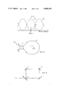
- FIG. 4 is a schematic representation of the present invention wherein an optical gyroscope uses as the beam splitter a directional coupler with three inlets and three outlets, i.e. a (3 ⁇ 3) directional coupler.
- FIG. 5 is a cross-sectional illustration of optical coupling between three equispaced optical fibers as in the directional coupler of FIG. 4.
- FIG. 6 shows the relationship between outputs P II (and P III ) of the gyroscope shown in FIG. 5 relative to rotation rate ⁇ .
- FIG. 1 shows, for example, the relationship between gyro output P I and rotation rate ⁇ .
- FIGS. 2 and 3 Such a problem occurs in the conventional optical gyroscope as shown, for example, in FIGS. 2 and 3.
- input beam P in is split into two by a directional coupler 1.
- the two split beams make round trips along the closed fiber loop 2, one propagating clockwise and the other propagating counter clockwise, and recombine at directional coupler 1.
- FIG. 3 an equivalent optical gyroscope is shown in which bulk optics are used instead of the all-guided wave optical components as illustrated in FIG. 2.
- Input beam P in is split by a bulk beam splitter 3.
- the split beams are folded by mirrors 4, 5 and 6 to make round trips in opposite directions.
- the beam splitters 1 and 3 in FIGS. 2 and 3, respectively have two inlets and two outlets. Thus, it is always possible to distinguish one inlet from the other inlet because one receives the input beam while the other does not.
- FIG. 4 is a schematic representation of the present invention in which a directional coupler 10 with three inlets and three outlets is used as the beam splitter. With respect to the center inlet waveguide 12, the two other waveguides 14 and 16 are indistinguishable.
- FIG. 5 a typical cross-sectional view of optical fibers defining directional coupler 10 in FIG. 4. Three equidistant or equispaced fibers a, b and c are illustrated, in which the coupling coefficients K ab (between the fibers a and b) and K ac (between the fibers a and c) are same.
- optical fibers a, b and c which define waveguides, may be disposed parallel or mutually twisted about each other as they traverse some length L (Fig. 4) across directional coupler 10 sufficient to establish evanescent coupling.
- Light from optical fibers b and c may be coupled into respective ends of optical fiber loop 20.
- Light introduced into respective ends of loop 20 propagate therethrough in mutually opposite directions and emerge at opposite respective ends to enter optical fiber waveguides b and c, this time propagating in the reverse direction.
- optical fibers b and c define waveguides of close proximity, as illustrated in FIG. 5, to allow mutual interference of the beams at directional coupler 10.
- directional coupler 10 comprises three optical waveguides, such as optical fibers, which lie in coextensive adjacency whereby laser light transported through waveguide 12 is equally coupled by evanescent coupling into equidistant waveguides 14 and 16.
- Waveguide 12 is relatively short.
- Waveguides 14 and 16 may also be of short lengths, in which case it is necessary to couple light from their ends into respective ends of the optical fiber forming loop 20.
- waveguides 14 and 16 may be integral extensions of the optical fiber waveguide defining loop 20. Beams returning from round trips through loop 20 are directed through lengths of waveguides 14 and 16 in close adJacency for mixing for mutual interference prior to separation as P II and P III , as shown in FIG. 4.
- Waveguides 12, 14 and 16 may be fixedly carried in a substrate not illustrated to maintain their relative spacings from each other.
- optical fibers define the waveguide, they may be disposed either parallel or mutually twisted in a substrate such as a suitable liquid or set epoxy. Otherwise, the waveguides may be diffused, for example, into a substrate at controlled locations and depths such that their equidistances are maintained as defined in FIG. 5.
- Directional couplers 1 and 10 employ evanescent field coupling between two or more optical fibers in adjacency. Such coupling is more fully described in U.S. Pat. No. 4,264,126 issued Apr. 28, 1981 to Sang K. Sheem.
- the couplers perform a beam splitting function and are used instead of the more conventional bulk-type partially reflective mirrors.
- FIGS. 1 and 6 solid line
- ⁇ /2 phase bias in the optical fiber loop.
- the present invention accomplishes this objective by using a (3 ⁇ 3) directional coupler 10 as the beam splitter which is illustrated in FIG. 4.
- an optical beam P in from a laser (not illustrated) is launched into a port defined by the end of optical fiber 12, from which it is distributed to optical fiber 14 and 16 and among output ports P 1 , P 2 and P 3 .
- Beams P 2 and P 3 make round trips in opposite directions around loop 20 and reenter directional coupler 10 via fibers 14 and 16 to provide outputs P II and P III .
- Optical fiber 12 is not available as an output.
- the directional coupler mixes the returning fields over the three waveguides (optical fibers 12, 14 and 16) through evanescent field coupling. As shown in FIGS.
- Comparison of P II and P III may be made in FIGS. 6 with the output (solid line) of the conventional gyroscopes known in the prior art.
- the described (3 ⁇ 3) directional coupler of three input and three output ports operates automatically near maximum sensitivity at zero rotation. Therefore there is no need for a nonreciprocal phase bias in the fiber loop which would add noise and complexity to the system.
Abstract
Description
Claims (9)
Priority Applications (1)
| Application Number | Priority Date | Filing Date | Title |
|---|---|---|---|
| US06/320,999 US4440498A (en) | 1981-11-13 | 1981-11-13 | Optical fiber gyroscope with (3×3) directional coupler |
Applications Claiming Priority (1)
| Application Number | Priority Date | Filing Date | Title |
|---|---|---|---|
| US06/320,999 US4440498A (en) | 1981-11-13 | 1981-11-13 | Optical fiber gyroscope with (3×3) directional coupler |
Publications (1)
| Publication Number | Publication Date |
|---|---|
| US4440498A true US4440498A (en) | 1984-04-03 |
Family
ID=23248731
Family Applications (1)
| Application Number | Title | Priority Date | Filing Date |
|---|---|---|---|
| US06/320,999 Expired - Fee Related US4440498A (en) | 1981-11-13 | 1981-11-13 | Optical fiber gyroscope with (3×3) directional coupler |
Country Status (1)
| Country | Link |
|---|---|
| US (1) | US4440498A (en) |
Cited By (40)
| Publication number | Priority date | Publication date | Assignee | Title |
|---|---|---|---|---|
| US4589728A (en) * | 1983-08-26 | 1986-05-20 | Andrew Corporation | Optical fiber polarizer |
| US4662751A (en) * | 1985-09-24 | 1987-05-05 | The United States Of America As Represented By The Administrator Of The National Aeronautics And Space Administration | Closed loop fiber optic rotation sensor |
| US4669814A (en) * | 1982-08-02 | 1987-06-02 | Andrew Corporation | Single mode, single polarization optical fiber with accessible guiding region and method of forming directional coupler using same |
| US4697876A (en) * | 1983-02-25 | 1987-10-06 | Andrew Corporation | Fiber-optic rotation sensor |
| US4703287A (en) * | 1985-08-22 | 1987-10-27 | United Technologies Corporation | Phase modulator for fiber-optic sensors |
| US4755021A (en) * | 1982-08-02 | 1988-07-05 | Andrew Corporation | Self-aligning optical fiber directional coupler and fiber-ring optical rotation sensor using same |
| US4772084A (en) * | 1986-04-14 | 1988-09-20 | American Telephone And Telegraph Company At&T Bell Laboratories | Optical power splitter and polarization splitter |
| EP0329996A1 (en) * | 1988-02-25 | 1989-08-30 | Messerschmitt-Bölkow-Blohm Gesellschaft mit beschränkter Haftung | Fibre-optical gyroscope |
| US4950318A (en) * | 1982-08-02 | 1990-08-21 | Andrew Corporation | Method of joining self-aligning optical fibers |
| EP0392080A1 (en) * | 1989-04-12 | 1990-10-17 | Messerschmitt-Bölkow-Blohm Gesellschaft mit beschränkter Haftung | Method of signal evaluation for a fiber optic gyroscope |
| US4973122A (en) * | 1987-12-10 | 1990-11-27 | British Telecommunications Public Limited Company | Optical nonlinear cross-coupled interferometer and method utilizing same |
| EP0402565A1 (en) * | 1989-06-10 | 1990-12-19 | Messerschmitt-Bölkow-Blohm Gesellschaft mit beschränkter Haftung | Method of autocorrecting a fiber optic gyroscope using a 3x3-coupler |
| EP0412309A1 (en) * | 1989-08-09 | 1991-02-13 | Deutsche Aerospace AG | Fibre optic gyroscope of the Sagnac type |
| EP0412311A1 (en) * | 1989-08-09 | 1991-02-13 | Messerschmitt-Bölkow-Blohm Gesellschaft mit beschränkter Haftung | Fiber optic gyroscope of the Sagnac-type |
| EP0415004A2 (en) * | 1989-08-30 | 1991-03-06 | Messerschmitt-Bölkow-Blohm Gesellschaft mit beschränkter Haftung | Fibre optic gyroscope |
| US5018815A (en) * | 1985-01-31 | 1991-05-28 | Imperial Chemical Industries Plc | Fibre optic data network |
| US5029276A (en) * | 1989-04-12 | 1991-07-02 | Messerschmitt-Boelkow-Blohm | Circuit arrangement for forming the difference and the sum of two detected signals |
| US5071214A (en) * | 1988-05-12 | 1991-12-10 | The Commonwealth Of Australia | Interferometric fibre optic network |
| DE4134312A1 (en) * | 1991-10-17 | 1993-04-22 | Deutsche Aerospace | FIBER OPTICAL GYPSY |
| US5486921A (en) * | 1994-04-05 | 1996-01-23 | Litton Systems, Inc. | Optimum coupler configuration for fiber optic rate gyroscope using [3×] coupler |
| US5636022A (en) * | 1994-07-29 | 1997-06-03 | Litton Systems, Inc. | Closed loop unmodulated fiber optic rate gyroscope with 3×3 coupler and method |
| US5777737A (en) * | 1994-07-22 | 1998-07-07 | Litton Systems, Inc. | Apparatus and method for processing signals output from fiber optic rate gyroscope having 3×3 coupler |
| DE19706858C1 (en) * | 1997-02-21 | 1998-08-13 | Daimler Benz Aerospace Ag | Procedure for determining the rate of rotation |
| DE19806423C1 (en) * | 1998-02-17 | 1999-07-29 | Lfk Gmbh | Data rate threshold value detector for fiber gyroscope |
| WO1999051942A1 (en) * | 1998-04-03 | 1999-10-14 | The Board Of Trustees Of The Leland Stanford Junior University | Fiber optic acoustic sensor array based on sagnac interferometer |
| US6034924A (en) * | 1998-04-03 | 2000-03-07 | The Board Of Trustees Of The Leland Stanford Junior Univerisity | Folded sagnac sensor array |
| US6278657B1 (en) | 1998-04-03 | 2001-08-21 | The Board Of Trustees Of The Leland Stanford Junior University | Folded sagnac sensor array |
| US6445455B1 (en) | 2000-05-23 | 2002-09-03 | Northrop Grumman Corporation | Phase and intensity modulated IFOG |
| US6667935B2 (en) | 1998-04-03 | 2003-12-23 | The Board Of Trustees Of The Leland Stanford Junior University | Apparatus and method for processing optical signals from two delay coils to increase the dynamic range of a sagnac-based fiber optic sensor array |
| US6678211B2 (en) | 1998-04-03 | 2004-01-13 | The Board Of Trustees Of The Leland Stanford Junior University | Amplified tree structure technology for fiber optic sensor arrays |
| US6724319B1 (en) | 1999-10-29 | 2004-04-20 | Litton Systems, Inc. | Acoustic sensing system for downhole seismic applications utilizing an array of fiber optic sensors |
| US6728165B1 (en) | 1999-10-29 | 2004-04-27 | Litton Systems, Inc. | Acoustic sensing system for downhole seismic applications utilizing an array of fiber optic sensors |
| CN101608930B (en) * | 2009-07-09 | 2012-05-23 | 复旦大学 | Realizing method of pi/2 phase bias of optical fiber interferometer |
| US20140340690A1 (en) * | 2012-01-16 | 2014-11-20 | Ixblue | Guided optical router, fibre-optic interferometer integrating such an optical router and method of guided optical routing |
| US9212912B1 (en) | 2014-10-24 | 2015-12-15 | Honeywell International Inc. | Ring laser gyroscope on a chip with doppler-broadened gain medium |
| US20170199037A1 (en) * | 2014-10-02 | 2017-07-13 | Faquir Chand Jain | Fiber Optic Gyroscope With Integrated WaveGuide Couplers and Opto-Electronic Devices |
| US9823075B2 (en) | 2013-01-10 | 2017-11-21 | Xiaotian Steve Yao | Non-interferometric optical gyroscope based on polarization sensing |
| CN108507558A (en) * | 2018-03-28 | 2018-09-07 | 株洲菲斯罗克光电技术有限公司 | A kind of lightweight three-axis integrative fibre optic gyroscope |
| CN116045940A (en) * | 2023-03-31 | 2023-05-02 | 中国船舶集团有限公司第七〇七研究所 | Micro-ring coupling structure based on integrated optical gyroscope and adjusting method |
| CN108507558B (en) * | 2018-03-28 | 2024-04-30 | 株洲菲斯罗克光电科技股份有限公司 | Lightweight triaxial integrated optical fiber gyroscope |
Citations (3)
| Publication number | Priority date | Publication date | Assignee | Title |
|---|---|---|---|---|
| US3102953A (en) * | 1958-07-09 | 1963-09-03 | Maxson Electronics Corp | Electromagnetic wave gyroscopes or angular velocity measuring systems |
| US4013365A (en) * | 1974-08-29 | 1977-03-22 | The University Of Utah | Laser gyroscope |
| JPS55157701A (en) * | 1979-05-29 | 1980-12-08 | Hitachi Ltd | Production of photo branching and coupling device |
-
1981
- 1981-11-13 US US06/320,999 patent/US4440498A/en not_active Expired - Fee Related
Patent Citations (3)
| Publication number | Priority date | Publication date | Assignee | Title |
|---|---|---|---|---|
| US3102953A (en) * | 1958-07-09 | 1963-09-03 | Maxson Electronics Corp | Electromagnetic wave gyroscopes or angular velocity measuring systems |
| US4013365A (en) * | 1974-08-29 | 1977-03-22 | The University Of Utah | Laser gyroscope |
| JPS55157701A (en) * | 1979-05-29 | 1980-12-08 | Hitachi Ltd | Production of photo branching and coupling device |
Non-Patent Citations (2)
| Title |
|---|
| Sheem et al., "Optical Fiber Gyroscope with (3×2) Guided-Wave Split," Third International Conference on Integrated Optics and Optical Fiber Communications, San Francisco, Ca., USA (Apr. 27-29, 1981), pp. 116-117. |
| Sheem et al., Optical Fiber Gyroscope with (3 2) Guided Wave Splitter, Third International Conference on Integrated Optics and Optical Fiber Communications, San Francisco, Ca., USA (Apr. 27 29, 1981), pp. 116 117. * |
Cited By (59)
| Publication number | Priority date | Publication date | Assignee | Title |
|---|---|---|---|---|
| US4950318A (en) * | 1982-08-02 | 1990-08-21 | Andrew Corporation | Method of joining self-aligning optical fibers |
| US4669814A (en) * | 1982-08-02 | 1987-06-02 | Andrew Corporation | Single mode, single polarization optical fiber with accessible guiding region and method of forming directional coupler using same |
| US4755021A (en) * | 1982-08-02 | 1988-07-05 | Andrew Corporation | Self-aligning optical fiber directional coupler and fiber-ring optical rotation sensor using same |
| US4697876A (en) * | 1983-02-25 | 1987-10-06 | Andrew Corporation | Fiber-optic rotation sensor |
| US4589728A (en) * | 1983-08-26 | 1986-05-20 | Andrew Corporation | Optical fiber polarizer |
| US5018815A (en) * | 1985-01-31 | 1991-05-28 | Imperial Chemical Industries Plc | Fibre optic data network |
| US4703287A (en) * | 1985-08-22 | 1987-10-27 | United Technologies Corporation | Phase modulator for fiber-optic sensors |
| US4662751A (en) * | 1985-09-24 | 1987-05-05 | The United States Of America As Represented By The Administrator Of The National Aeronautics And Space Administration | Closed loop fiber optic rotation sensor |
| US4772084A (en) * | 1986-04-14 | 1988-09-20 | American Telephone And Telegraph Company At&T Bell Laboratories | Optical power splitter and polarization splitter |
| US4973122A (en) * | 1987-12-10 | 1990-11-27 | British Telecommunications Public Limited Company | Optical nonlinear cross-coupled interferometer and method utilizing same |
| DE3805904A1 (en) * | 1988-02-25 | 1989-08-31 | Messerschmitt Boelkow Blohm | FIBER GYRO |
| US4944590A (en) * | 1988-02-25 | 1990-07-31 | Messerschmitt-Bolkow-Blohm Gmbh | Optical-fiber gyroscope of sagnac type having a fiber-optic loop and 3×3 coupler |
| EP0329996A1 (en) * | 1988-02-25 | 1989-08-30 | Messerschmitt-Bölkow-Blohm Gesellschaft mit beschränkter Haftung | Fibre-optical gyroscope |
| US5071214A (en) * | 1988-05-12 | 1991-12-10 | The Commonwealth Of Australia | Interferometric fibre optic network |
| EP0392080A1 (en) * | 1989-04-12 | 1990-10-17 | Messerschmitt-Bölkow-Blohm Gesellschaft mit beschränkter Haftung | Method of signal evaluation for a fiber optic gyroscope |
| DE3912005A1 (en) * | 1989-04-12 | 1990-10-18 | Messerschmitt Boelkow Blohm | METHOD FOR EVALUATING SIGNALS FOR A FIBER GYRO |
| US5080488A (en) * | 1989-04-12 | 1992-01-14 | Messerschmitt-Boelkow-Blohm Gmbh | Method for evaluating signals of a fiber optical gyroscope or sagnac interferometer |
| US5029276A (en) * | 1989-04-12 | 1991-07-02 | Messerschmitt-Boelkow-Blohm | Circuit arrangement for forming the difference and the sum of two detected signals |
| US5146292A (en) * | 1989-06-10 | 1992-09-08 | Messerschmitt-Boelkow-Blohm Gmbh | Method for self-correction of a fiber gyroscope with a 3×3-coupler |
| DE3919060A1 (en) * | 1989-06-10 | 1990-12-20 | Messerschmitt Boelkow Blohm | METHOD FOR SELF-CORRECTING A FIBER GYRO WITH 3X3 COUPLER |
| EP0402565A1 (en) * | 1989-06-10 | 1990-12-19 | Messerschmitt-Bölkow-Blohm Gesellschaft mit beschränkter Haftung | Method of autocorrecting a fiber optic gyroscope using a 3x3-coupler |
| DE3926313A1 (en) * | 1989-08-09 | 1991-02-14 | Messerschmitt Boelkow Blohm | SAGNAC TYPE FIBER GYRO |
| DE3926312A1 (en) * | 1989-08-09 | 1991-02-14 | Messerschmitt Boelkow Blohm | SAGNAC TYPE FIBER GYRO |
| EP0412311A1 (en) * | 1989-08-09 | 1991-02-13 | Messerschmitt-Bölkow-Blohm Gesellschaft mit beschränkter Haftung | Fiber optic gyroscope of the Sagnac-type |
| EP0412309A1 (en) * | 1989-08-09 | 1991-02-13 | Deutsche Aerospace AG | Fibre optic gyroscope of the Sagnac type |
| US5118190A (en) * | 1989-08-09 | 1992-06-02 | Messerschmitt-Bolkow-Blohm Gmbh | Sagnac-type fiber-optic gyroscope |
| DE3928715A1 (en) * | 1989-08-30 | 1991-05-08 | Messerschmitt Boelkow Blohm | FIBER GYRO |
| US5037204A (en) * | 1989-08-30 | 1991-08-06 | Messerschmitt-Bolkow-Blohm Gmbh | Optical-fiber gyroscope |
| EP0415004A3 (en) * | 1989-08-30 | 1991-04-17 | Messerschmitt-Boelkow-Blohm Gesellschaft Mit Beschraenkter Haftung | Fibre optic gyroscope |
| EP0415004A2 (en) * | 1989-08-30 | 1991-03-06 | Messerschmitt-Bölkow-Blohm Gesellschaft mit beschränkter Haftung | Fibre optic gyroscope |
| DE4134312A1 (en) * | 1991-10-17 | 1993-04-22 | Deutsche Aerospace | FIBER OPTICAL GYPSY |
| US5373361A (en) * | 1991-10-17 | 1994-12-13 | Deutsche Aerospace Patentabteilung | Fiber optic gyroscope including a 3×3 coupler and a contrast adjusting element |
| US5486921A (en) * | 1994-04-05 | 1996-01-23 | Litton Systems, Inc. | Optimum coupler configuration for fiber optic rate gyroscope using [3×] coupler |
| US5777737A (en) * | 1994-07-22 | 1998-07-07 | Litton Systems, Inc. | Apparatus and method for processing signals output from fiber optic rate gyroscope having 3×3 coupler |
| US5636022A (en) * | 1994-07-29 | 1997-06-03 | Litton Systems, Inc. | Closed loop unmodulated fiber optic rate gyroscope with 3×3 coupler and method |
| DE19706858C1 (en) * | 1997-02-21 | 1998-08-13 | Daimler Benz Aerospace Ag | Procedure for determining the rate of rotation |
| US5995211A (en) * | 1997-02-21 | 1999-11-30 | Daimlerchrysler Aerospace Aktiengesellschaft | Method for determining the rate of rotation |
| DE19806423C1 (en) * | 1998-02-17 | 1999-07-29 | Lfk Gmbh | Data rate threshold value detector for fiber gyroscope |
| US6034924A (en) * | 1998-04-03 | 2000-03-07 | The Board Of Trustees Of The Leland Stanford Junior Univerisity | Folded sagnac sensor array |
| WO1999051942A1 (en) * | 1998-04-03 | 1999-10-14 | The Board Of Trustees Of The Leland Stanford Junior University | Fiber optic acoustic sensor array based on sagnac interferometer |
| US6097486A (en) * | 1998-04-03 | 2000-08-01 | The Board Of Trustees Of The Leland Stanford Junior University | Fiber optic acoustic sensor array based on Sagnac interferometer |
| US6278657B1 (en) | 1998-04-03 | 2001-08-21 | The Board Of Trustees Of The Leland Stanford Junior University | Folded sagnac sensor array |
| US6529444B2 (en) | 1998-04-03 | 2003-03-04 | The Board Of Trustees Of The Leland Stanford Junior University | Folded sagnac sensor array |
| US6667935B2 (en) | 1998-04-03 | 2003-12-23 | The Board Of Trustees Of The Leland Stanford Junior University | Apparatus and method for processing optical signals from two delay coils to increase the dynamic range of a sagnac-based fiber optic sensor array |
| US6678211B2 (en) | 1998-04-03 | 2004-01-13 | The Board Of Trustees Of The Leland Stanford Junior University | Amplified tree structure technology for fiber optic sensor arrays |
| US6724319B1 (en) | 1999-10-29 | 2004-04-20 | Litton Systems, Inc. | Acoustic sensing system for downhole seismic applications utilizing an array of fiber optic sensors |
| US6728165B1 (en) | 1999-10-29 | 2004-04-27 | Litton Systems, Inc. | Acoustic sensing system for downhole seismic applications utilizing an array of fiber optic sensors |
| US6445455B1 (en) | 2000-05-23 | 2002-09-03 | Northrop Grumman Corporation | Phase and intensity modulated IFOG |
| CN101608930B (en) * | 2009-07-09 | 2012-05-23 | 复旦大学 | Realizing method of pi/2 phase bias of optical fiber interferometer |
| US20140340690A1 (en) * | 2012-01-16 | 2014-11-20 | Ixblue | Guided optical router, fibre-optic interferometer integrating such an optical router and method of guided optical routing |
| US9823075B2 (en) | 2013-01-10 | 2017-11-21 | Xiaotian Steve Yao | Non-interferometric optical gyroscope based on polarization sensing |
| US10451420B2 (en) | 2013-01-10 | 2019-10-22 | Xiaotian Steve Yao | Non-interferometric optical gyroscope based on polarization sensing |
| US11268811B2 (en) | 2013-01-10 | 2022-03-08 | NuVision Photonics, Inc. | Non-interferometric optical gyroscope based on polarization sensing |
| US20170199037A1 (en) * | 2014-10-02 | 2017-07-13 | Faquir Chand Jain | Fiber Optic Gyroscope With Integrated WaveGuide Couplers and Opto-Electronic Devices |
| US10041797B2 (en) * | 2014-10-02 | 2018-08-07 | Faquir Chand Jain | Fiber optic gyroscope with 3×3 and 2×2 waveguide couplers |
| US9212912B1 (en) | 2014-10-24 | 2015-12-15 | Honeywell International Inc. | Ring laser gyroscope on a chip with doppler-broadened gain medium |
| CN108507558A (en) * | 2018-03-28 | 2018-09-07 | 株洲菲斯罗克光电技术有限公司 | A kind of lightweight three-axis integrative fibre optic gyroscope |
| CN108507558B (en) * | 2018-03-28 | 2024-04-30 | 株洲菲斯罗克光电科技股份有限公司 | Lightweight triaxial integrated optical fiber gyroscope |
| CN116045940A (en) * | 2023-03-31 | 2023-05-02 | 中国船舶集团有限公司第七〇七研究所 | Micro-ring coupling structure based on integrated optical gyroscope and adjusting method |
Similar Documents
| Publication | Publication Date | Title |
|---|---|---|
| US4440498A (en) | Optical fiber gyroscope with (3×3) directional coupler | |
| EP0434767B1 (en) | Passive ring resonator gyro with polarization rotating ring path | |
| US4120588A (en) | Multiple path configuration for a laser interferometer | |
| US4653917A (en) | Fiber optic gyroscope operating with unpolarized light source | |
| US4514088A (en) | Single-coupler guided-wave passive resonant-ring optical-gyro instrument | |
| JPH07117417B2 (en) | Fiber optic rotation sensor using unpolarized light | |
| US6801319B2 (en) | Symmetrical depolarized fiber optic gyroscope | |
| US4445780A (en) | Fiber optic rotation-sensing gyroscope with (3×2) coupler | |
| EP0563279B1 (en) | Fiber optic gyro | |
| US4479715A (en) | Optical rotation-sensing interferometer with (3×3)-(2×2) directional coupler | |
| US5323415A (en) | Brillouin ring laser | |
| US4382681A (en) | Measurement of rotation rate using Sagnac effect | |
| AU549389B2 (en) | Fiber optic rotation sensor | |
| JPH03162617A (en) | Optical fiber resonator interferometer gyroscope | |
| EP0078931B1 (en) | Angular rate sensor | |
| US4283144A (en) | Method of fiber interferometry zero fringe shift referencing using passive optical couplers | |
| US4420259A (en) | Double coupled dual input rate sensor | |
| US5351124A (en) | Birefringent component axis alignment detector | |
| US5214487A (en) | Fiber optic gyro | |
| US5486921A (en) | Optimum coupler configuration for fiber optic rate gyroscope using [3×] coupler | |
| EP1722194A2 (en) | Apparatus comprising a waveguide with reduced higher modes | |
| US20230349696A1 (en) | Fiber-optic gyroscope with a dual-injection polarization- maintaining 3x3 directional coupler for enhanced measurement sensitivity through heterodyne | |
| US4865449A (en) | Optical signal rejection filter and application of said filter to ring interferometers | |
| WO1997021981A1 (en) | Optimum configuration of a 3 x 3 coupler for a fiber optic gyroscope | |
| Youngquist et al. | Asymmetric Losses in Directional Couplers; Effects on Sagnac and Mach Zehnder Fiber Interferometers |
Legal Events
| Date | Code | Title | Description |
|---|---|---|---|
| AS | Assignment |
Owner name: UNITED STATES OF AMERICA AS REPRESENTED BY THE SEC Free format text: ASSIGNMENT OF ASSIGNORS INTEREST.;ASSIGNOR:SHEEM, SANG K.;REEL/FRAME:003959/0742 Effective date: 19811102 Owner name: NAVY, UNITED STATES OF AMERICA AS REPRESENTED BY T Free format text: ASSIGNMENT OF ASSIGNORS INTEREST;ASSIGNOR:SHEEM, SANG K.;REEL/FRAME:003959/0742 Effective date: 19811102 |
|
| MAFP | Maintenance fee payment |
Free format text: PAYMENT OF MAINTENANCE FEE, 4TH YEAR, PL 96-517 (ORIGINAL EVENT CODE: M170); ENTITY STATUS OF PATENT OWNER: LARGE ENTITY Year of fee payment: 4 |
|
| MAFP | Maintenance fee payment |
Free format text: PAYMENT OF MAINTENANCE FEE, 8TH YEAR, PL 96-517 (ORIGINAL EVENT CODE: M171); ENTITY STATUS OF PATENT OWNER: LARGE ENTITY Year of fee payment: 8 |
|
| FEPP | Fee payment procedure |
Free format text: MAINTENANCE FEE REMINDER MAILED (ORIGINAL EVENT CODE: REM.); ENTITY STATUS OF PATENT OWNER: LARGE ENTITY |
|
| LAPS | Lapse for failure to pay maintenance fees | ||
| FP | Lapsed due to failure to pay maintenance fee |
Effective date: 19960403 |
|
| STCH | Information on status: patent discontinuation |
Free format text: PATENT EXPIRED DUE TO NONPAYMENT OF MAINTENANCE FEES UNDER 37 CFR 1.362 |