US4423436A - Image pickup apparatus - Google Patents
Image pickup apparatus Download PDFInfo
- Publication number
- US4423436A US4423436A US06/260,299 US26029981A US4423436A US 4423436 A US4423436 A US 4423436A US 26029981 A US26029981 A US 26029981A US 4423436 A US4423436 A US 4423436A
- Authority
- US
- United States
- Prior art keywords
- image
- light source
- video signal
- signal
- illumination
- Prior art date
- Legal status (The legal status is an assumption and is not a legal conclusion. Google has not performed a legal analysis and makes no representation as to the accuracy of the status listed.)
- Expired - Lifetime
Links
Images


Classifications
-
- A—HUMAN NECESSITIES
- A61—MEDICAL OR VETERINARY SCIENCE; HYGIENE
- A61B—DIAGNOSIS; SURGERY; IDENTIFICATION
- A61B1/00—Instruments for performing medical examinations of the interior of cavities or tubes of the body by visual or photographical inspection, e.g. endoscopes; Illuminating arrangements therefor
- A61B1/04—Instruments for performing medical examinations of the interior of cavities or tubes of the body by visual or photographical inspection, e.g. endoscopes; Illuminating arrangements therefor combined with photographic or television appliances
- A61B1/042—Instruments for performing medical examinations of the interior of cavities or tubes of the body by visual or photographical inspection, e.g. endoscopes; Illuminating arrangements therefor combined with photographic or television appliances characterised by a proximal camera, e.g. a CCD camera
-
- H—ELECTRICITY
- H04—ELECTRIC COMMUNICATION TECHNIQUE
- H04N—PICTORIAL COMMUNICATION, e.g. TELEVISION
- H04N23/00—Cameras or camera modules comprising electronic image sensors; Control thereof
- H04N23/70—Circuitry for compensating brightness variation in the scene
- H04N23/74—Circuitry for compensating brightness variation in the scene by influencing the scene brightness using illuminating means
-
- H—ELECTRICITY
- H04—ELECTRIC COMMUNICATION TECHNIQUE
- H04N—PICTORIAL COMMUNICATION, e.g. TELEVISION
- H04N23/00—Cameras or camera modules comprising electronic image sensors; Control thereof
- H04N23/50—Constructional details
- H04N23/555—Constructional details for picking-up images in sites, inaccessible due to their dimensions or hazardous conditions, e.g. endoscopes or borescopes
Definitions
- This invention relates to an image pickup device coupled to, for example, a prescribed optical image transmission device to produce predetermined video signals, and more particularly to a television camera apparatus jointly used with a fiberscope to carry out a particular function such as an iris servo control.
- iris servo function is defined to mean a function of generating a video signal always having a prescribed voltage level, regardless of the brightness of a foreground subject whose image is to be picked up.
- This iris servo function fundamentally corresponds to the electric eye (EE) mechanism of the ordinary camera.
- the iris servo device of the conventional television camera generally comprises the undermentioned servo system. Namely, the conventional iris servo device detects the average voltage level or peak level of video signals obtained from a television camera.
- the iris mechanism of the television camera is servo-controlled in accordance with the result of said detection, thereby controlling the brightness of a foreground subject entering the target plane of the image pickup device of the television camera to a fixed level.
- an automatic gain control (AGC) circuit has been used as means for electrically fixing the voltage level of the aforesaid video signal.
- Another known process of controlling the voltage of the video signal to a fixed level comprises the joint use of the AGC circuit and the aforementioned mechanical servo device.
- the mechanical servo device and AGC circuit are actuated independently of each other.
- the electric servo loop (AGC circuit) does not work.
- the electric servo loop (AGC circuit) is operated, the mechanical servo loop becomes inoperative.
- This invention has been accomplished in view of the above-mentioned circumstances, and is intended to provide an image pickup apparatus which can unfailingly follow broad range changes in the brightness of a foreground subject with a high S/N ratio retained.
- an impage pickup apparatus which comprises:
- light source means for providing an illumination light
- illumination means coupled to said light source means for transmitting the illumination light to a foreground subject to be illuminated
- image transmission means for sensing an optical image of the foreground subject illuminated by said illumination means and transmitting the optical image
- the illumination means and image transmission means being part of an endoscope
- image signal conversion means coupled to said image transmission means for converting the optical image into a video signal
- said light source means, illumination means, image transmission means, image signal conversion means and feedback means jointly constitute an automatic level control loop which is continuously actuated as to continuously set the amount of illumination light to cause the video signal to be at a substantially constant prescribed level.
- a television camera provided with an iris servo function embodying this invention makes it unnecessary to manually change over the operation of the mechanical and electric servo loops, thereby enabling the operator to devote his attention to the photographing of a foreground subject.
- the luminance of a light source can be varied over a broad range in accordance with the brightness of a foreground subject, enabling the image pickup means always to receive an optical image having a sufficient brightness, and consequently assuring the production of a video signal having a high S/N ratio.
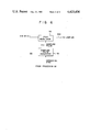
- FIG. 1 shows the arrangement of an image pickup apparatus embodying this invention
- FIG. 2 is a waveform diagram illustrating the manner in which DC restoration is carried out in the image pickup apparatus of FIG. 1;
- FIG. 3 is a concrete circuit arrangement of a comparator used with the image pickup apparatus of FIG. 1;
- FIGS. 4 and 5 are modifications of FIG. 3;
- FIG. 6 is a modification of FIG. 1.
- a flexible tube 10 is connected to a control section 8 of the endoscope.
- the flexible tube 10 is connected to a distal end portion 14 by means of a bending section 12.
- the tip of the distal end portion 14 is fitted with a light guide 16 and also an object lens 18 included in an observation optical system.
- the light guide 16 is connected to a light source 21 by means of a light guide fiber bundle 20.
- the light source 21 is formed of a white light lamp 21b provided with a reflector 21a.
- the object lens 18 is connected to an eyepiece section 24 by means of an image guide fiber bundle 22.
- An optical system 28 and image pickup tube 30 are concentrically arranged with the optical axis of the proximal end of the image guide fiber bundle 22 fixed to the eyepiece section 24.
- the light source 21 supplies an illumination light to the light guide fiber bundle 20 acting as illumination means for projecting an illumination light on a foreground subject 17.
- the image guide fiber bundle 22 acts as image transmission means for conducting the optical image of the foreground subject 17 to the image pickup tube 30.
- the image pickup tube 30 may be formed of a vidicon or CCD image sensor element.
- a distance between a target plane 30a of the image pickup tube 30 and the optical system 38 is so adjusted as to cause the optical image of the foreground subject 17 to be accurately focused on the target plane 30a.
- This focus adjustment can be effected by a focus control apparatus disclosed in Japanese patent application Nos. 58,399/80 or 79,742/80.
- An output video signal E10 from the image pickup tube 30 is supplied to a video signal-processing circuit 32, which in turn processes said output video signal E10 as prescribed and sends forth a video signal E12 adapted for the ordinary television system.
- a video signal-processing circuit 32 For detailed information on said video signal-processing circuit 32, reference is made to "ITV camera" published by the Japan Broadcasting Publication Association.
- the image pickup tube 30 and video signal-processing circuit 32 (or the type combined with a focus control device) jointly constitute image pickup means 33 for converting the optical image of the foreground subject 17 transmitted by the image guide fiber bundle 22 into a video signal E12.
- the video signal E12 is supplied to, for example, a recording device (VTR) or monitor TV device, and also to a comparator 34.
- the comparator 34 compares the potential of the video signal E12 with a reference potential V ref , and sends forth a first signal E14 corresponding to a difference between both potentials.
- the first signal E14 is conducted to a clamp circuit 36. At this time a level approaching the block portion of the first signal E14 is clamped in the clamp circuit 36 when a clamp pulse CL is issued. As a result, the D.C. component of the first signal E14 is restored.
- the clamp pulse CL is sent forth in synchronism with a horizontal synchronization signal included in the video signal E12.
- FIGS. 2a and 2b show waveforms illustrating the manner in which the above-mentioned D.C. component of the first signal E14 is restored.
- FIGS. 2a and 2b indicate that where the clamp pulse CL is issued, the D.C. level of the first signal E14 at a prescribed point P c is clamped.
- a second signal E16 corresponding to the D.C. component thus restored is supplied to a low pass filter (LPF) 38.
- a third signal E18 which has been fully stripped of ripple components by the LPF 38 is amplified by an inverted amplifier 40 into a fourth signal E20.
- the third signal E18 corresponds to the average of the second signal E16.
- the fourth signal E20 is amplified by a current amplifier 42 into a light source drive signal E22 having a sufficient amount of energy.
- This light source drive signal E22 is supplied to the lamp 21b of light source 21.
- the elements 34 to 42 jointly constitute feedback means 44 which converts the video signal E12 into the light source device signal E22 and feeds said light source drive signal E22 back to the light source 21.
- the light source 21, light guide fiber bundle 20, image guide fiber bundle 22, image pickup means 33 and feedback means 44 jointly constitute an automatic level control loop so actuated as to cause the voltage of the video signal E12 to be set at such a prescribed level as corresponds to the reference potential V ref .
- the light guide 16 is so spaced from the foreground subject 17 as to cause only a dark light to be projected on the target plane 30a of the image pickup tube 30.
- the video signal E12 is decreased in voltage level to reduce a difference between the potential of said signal E12 and the reference potential V ref , causing the first signal E14 to fall in voltage level, with a rise in the voltage level of the light source drive signal E22.
- the lamp 21b gets brighter, enabling a larger amount of light to be supplied to the foreground subject 17. Therefore, a brighter light is projected on the target plane 30a of the image pickup tube 30 with a rise in the voltage level of the video signal E12. Conversely where a brighter light is projected on the target plane 30a, then a difference between the potential of the video signal E12 and reference potential V ref increases to cause the lamp 21b to get darker to the corresponding extent.
- the above-mentioned automatic voltage level control operation is carried out in such a manner as minimizes the absolute value of a difference between the potential of the video signal E12 and reference potential V ref .
- the extent to which the voltage level of the video signal E12 is controlled by the aforesaid automatic control loop is defined on the basis of the reference potential V ref .
- the automatic control loop is allowed to have a sufficient transfer function insofar as said control loop can be rendered stable, then the voltage of the video signal E12 is always set at a prescribed level corresponding to the reference potential V ref .
- the voltage of the video signal E12 is always set at a substantially fixed level, regardless of the deterioration (changes with time) of the lamp 21b, variations in the sensitivity of the image pickup tube 30 caused, for example, by changes in ambient temperature, and changes in the distance between the foreground subject 17 and the distal end portion 14 of the endoscope.
- This fact means that an optical image can be projected on the target plane 30a of the image pickup tube 30 with a substantially stabilized brightness, thereby assuring the production of a video signal E12 having a high S/N ratio.
- FIG. 3 shows the concrete arrangement of the comparator 34 included in FIG. 1.
- the video signal E12 is supplied to a slider of a variable resistor VR34 through resistors R34 1 and R34 2 . Both ends of the variable resistor 34 are impressed with a positive potential +V S and a negative potential -V S .
- the reference potential V ref is drawn out of the slider of the variable resistor VR34.
- the first signal E14 is sent forth from the junction of the resistors R34 1 and R34 2 .
- FIGS. 4 and 5 are modifications of FIG. 3.
- the video signal E12 is supplied to the non-inverted input terminal of an operational amplifier A34.
- the reference potential V ref is supplied to the inverted input terminal of said operational amplifier A34.
- the reference potential V ref is drawn out from the slider of the variable resistor VR34 as in FIG. 3.
- the clamp pulse CL is sampled and held in a sample/hold cicuit 35 when a horizontal synchronizing pulse is issued, thereby producing a reference potential V ref corresponding to the clamp pulse CL.
- FIG. 6 is a modification of the feedback means 44 of FIG. 1.
- FIG. 6 represents the application of a conventional PWM or PCM modulator 50 which is supplied with the signal E18 or E14 corresponding to the video signal E12.
- the horizontal synchronizing pulse used in the processor 32 is delivered to a sampling pulse generator 52, which may be formed of a frequency multiplier or frequency divider.
- This sampling pulse generator 52 issues a sampling pulse PS upon receipt of the horizontal synchronizing pulse.
- the sampling pulse PS is supplied to the above-mentioned modulator 50, which produces a drive signal E22 having a duty cycle corresponding to the DC level of the signal E18 which is supplied to said modulator 50.
- the brightness of the lamp 21b averaged in terms of time is substantially proportional to the duty cycle of said drive signal E22.
- the lamp 21b is intermittently operated in a timing synchronized with the horizontal scanning.
- the lamp 21b has such a heat capacity that even while the drive signal E22 is not issued, light emission is continued. Further visual persistence takes place in the image pickup tube. It is seen from the above-mentioned facts that if the modulator 50 carries out sampling at a properly selected rate, then the occurrence of a horizontal noise bar on the video image-reproducing screen can be practically suppressed.
- the modulator 50 which is only intermittently operated releases less heat than the amplifier 42 of FIG. 1, namely, consumes less power.
- the image pickup apparatus of this invention allows for the application of "IRIS SERVO APPARATUS" disclosed in Japanese patent application No. 56,867/80, filed by the same assignee.
- a second automatic level control system as set forth in the above-mentioned IRIS SERVO APPARATUS which is actuated when the automatic level control system shwon in FIG. 1 of the present patent application is saturated.
Abstract
Description
Claims (5)
Applications Claiming Priority (2)
| Application Number | Priority Date | Filing Date | Title |
|---|---|---|---|
| JP6134780A JPS56158636A (en) | 1980-05-09 | 1980-05-09 | Photographing apparatus |
| JP55-61347 | 1980-05-09 |
Publications (1)
| Publication Number | Publication Date |
|---|---|
| US4423436A true US4423436A (en) | 1983-12-27 |
Family
ID=13168504
Family Applications (1)
| Application Number | Title | Priority Date | Filing Date |
|---|---|---|---|
| US06/260,299 Expired - Lifetime US4423436A (en) | 1980-05-09 | 1981-05-04 | Image pickup apparatus |
Country Status (3)
| Country | Link |
|---|---|
| US (1) | US4423436A (en) |
| JP (1) | JPS56158636A (en) |
| DE (1) | DE3118341C2 (en) |
Cited By (29)
| Publication number | Priority date | Publication date | Assignee | Title |
|---|---|---|---|---|
| US4509077A (en) * | 1982-12-17 | 1985-04-02 | Ncr Canada Ltd-Ncr Canada Ltee | Automatic, self-diagnosing, electro-optical imaging system |
| US4523231A (en) * | 1983-01-26 | 1985-06-11 | Ncr Canada Ltd - Ncr Canada Ltee | Method and system for automatically detecting camera picture element failure |
| US4532918A (en) * | 1983-10-07 | 1985-08-06 | Welch Allyn Inc. | Endoscope signal level control |
| US4535758A (en) * | 1983-10-07 | 1985-08-20 | Welch Allyn Inc. | Signal level control for video system |
| US4570184A (en) * | 1984-11-09 | 1986-02-11 | North American Philips Corporation | Optimization of vidicon bias lighting |
| DE3530778A1 (en) * | 1984-08-31 | 1986-03-20 | Olympus Optical Co., Ltd., Tokio/Tokyo | ENDOSCOPE WITH A SOLID-BODY IMAGING DEVICE |
| US4591918A (en) * | 1983-04-18 | 1986-05-27 | Omron Tateisi Electronics Co. | Image sensor system |
| US4618254A (en) * | 1982-10-15 | 1986-10-21 | Ncr Canada Ltd | Automatic light control system |
| US4635123A (en) * | 1982-02-26 | 1987-01-06 | Canon Kabushiki Kaisha | Image pick-up device for use with an illuminating device |
| US4646724A (en) * | 1982-10-15 | 1987-03-03 | Olympus Optical Co., Ltd. | Endoscopic photographing apparatus |
| US4652916A (en) * | 1983-10-12 | 1987-03-24 | Omron Tateisi Electronics Co. | Image pick-up device |
| US4663657A (en) * | 1983-09-05 | 1987-05-05 | Olympus Optical Company, Ltd. | Image pickup apparatus for endoscopes |
| US4672437A (en) * | 1985-07-08 | 1987-06-09 | Honeywell Inc. | Fiber optic inspection system |
| US4682238A (en) * | 1986-01-29 | 1987-07-21 | The United States Of America As Represented By The United States Department Of Energy | Energy-efficient lighting system for television |
| US4688087A (en) * | 1985-03-19 | 1987-08-18 | Richard Wolf Gmbh | Light projector having a controllable intensity of illumination |
| US4713683A (en) * | 1984-08-31 | 1987-12-15 | Olympus Optical Co., Ltd. | Illuminating and synchronizing device for color imaging equipment |
| DE3806190A1 (en) * | 1987-02-27 | 1988-09-08 | Olympus Optical Co | ELECTRONIC ENDOSCOPE DEVICE |
| US4782386A (en) * | 1986-03-08 | 1988-11-01 | Richard Wolf Gmbh | Video endoscope with a light source operable in a continuous or stroboscopic mode |
| US4807291A (en) * | 1985-10-17 | 1989-02-21 | Richard Wolf Gmbh | Circuit for a flash stroboscope for examining vocal chord functions |
| US4845554A (en) * | 1986-12-19 | 1989-07-04 | Olympus Optical Co., Ltd. | Automatic light adjusting system for an endoscope using an externally fitter camera |
| US4870487A (en) * | 1986-11-13 | 1989-09-26 | Olympus Optical Co., Ltd. | Light source device for an endoscope which maintains a constant minimum-DC current |
| US4901142A (en) * | 1987-03-23 | 1990-02-13 | Olympus Optical Co., Ltd. | Video scope system |
| US5091779A (en) * | 1989-08-25 | 1992-02-25 | Richard Wolf Gmbh | Automatic light adjustment means for an endoscope |
| US5144481A (en) * | 1991-05-14 | 1992-09-01 | Pettito Sr John J | Submerged meter reading apparatus |
| DE4424114C1 (en) * | 1994-07-08 | 1995-06-01 | Kernforschungsz Karlsruhe | Three=dimensional video endoscope for medical use |
| US5807264A (en) * | 1995-04-11 | 1998-09-15 | Paltieli; Yoav | Endoscope apparatus and method for detecting cilia motion using multimode detection fibers to collect back-scattered light |
| US5946393A (en) * | 1997-02-10 | 1999-08-31 | Integration Associates, Inc. | Data access arrangement |
| US20050071166A1 (en) * | 2003-09-29 | 2005-03-31 | International Business Machines Corporation | Apparatus for the collection of data for performing automatic speech recognition |
| US20100191057A1 (en) * | 2008-07-28 | 2010-07-29 | Jansen Lex P | Penetrating member with direct visualization |
Families Citing this family (18)
| Publication number | Priority date | Publication date | Assignee | Title |
|---|---|---|---|---|
| JPS6055924A (en) * | 1983-09-05 | 1985-04-01 | オリンパス光学工業株式会社 | Automatic light control apparatus of endoscope |
| DE3432017C2 (en) * | 1983-09-05 | 1986-06-19 | Olympus Optical Co., Ltd., Tokio/Tokyo | Endoscope arrangement |
| DE3432393C2 (en) * | 1983-09-05 | 1986-06-19 | Olympus Optical Co., Ltd., Tokio/Tokyo | Automatic dimming device for an endoscope |
| DE3435598C2 (en) * | 1983-09-30 | 1986-06-19 | Olympus Optical Co., Ltd., Tokio/Tokyo | Endoscope arrangement |
| JPS6080428A (en) * | 1983-10-07 | 1985-05-08 | オリンパス光学工業株式会社 | Endoscope imaging system |
| JPS6164227A (en) * | 1984-09-07 | 1986-04-02 | オリンパス光学工業株式会社 | Endoscope system |
| US4731661A (en) * | 1984-11-16 | 1988-03-15 | Sharp Kabushiki Kaisha | Color document reader with white balance adjuster for determining light emission periods for a plurality of different-colored light sources and corresponding integration times for a light sensor by reading a white reference area |
| DE3635148A1 (en) * | 1985-12-31 | 1987-07-09 | Fraunhofer Ges Forschung | Control unit for the power supplied to an incandescent lamp |
| DE3635149A1 (en) * | 1985-12-31 | 1987-07-02 | Fraunhofer Ges Forschung | Device for controlling the illumination of scenes |
| JPS6313013A (en) * | 1986-07-04 | 1988-01-20 | Olympus Optical Co Ltd | Endoscope device |
| JP2587818B2 (en) * | 1986-11-19 | 1997-03-05 | オリンパス光学工業株式会社 | Light source dimming control device for external camera for medical endoscope |
| US4782819A (en) * | 1987-02-25 | 1988-11-08 | Adair Edwin Lloyd | Optical catheter |
| JPH0160212U (en) * | 1987-10-14 | 1989-04-17 | ||
| JP2823561B2 (en) * | 1988-02-26 | 1998-11-11 | オリンパス光学工業株式会社 | Automatic dimming control device for endoscope |
| DE3819612A1 (en) * | 1988-06-09 | 1989-12-14 | Unomat Gmbh & Co Kg | Video camera with associated video light |
| JP2821141B2 (en) * | 1988-07-28 | 1998-11-05 | オリンパス光学工業株式会社 | Automatic dimming control device for endoscope |
| DE3935297A1 (en) * | 1989-10-24 | 1991-04-25 | Wolf Gmbh Richard | DEVICE FOR AUTOMATIC LIGHT SUPPLY CONTROL OF ENDOSCOPES |
| JPH03114802U (en) * | 1990-03-10 | 1991-11-26 |
Citations (7)
| Publication number | Priority date | Publication date | Assignee | Title |
|---|---|---|---|---|
| US3555181A (en) * | 1968-06-05 | 1971-01-12 | Bell Telephone Labor Inc | Automatic video level control employing iris and amplifier gain adjustments |
| US3602641A (en) * | 1968-09-27 | 1971-08-31 | Philips Corp | Dark current compensation circuit |
| US3678190A (en) * | 1966-12-21 | 1972-07-18 | Bunker Ramo | Automatic photo comparision system |
| US3835247A (en) * | 1971-05-11 | 1974-09-10 | Image Analysing Computers Ltd | Field illumination for image analysis |
| US3918028A (en) * | 1973-01-05 | 1975-11-04 | Data Source Corp | Hand held optical reader |
| US3944979A (en) * | 1974-12-23 | 1976-03-16 | Data Source Corporation | Method and apparatus for illuminating an object bearing indicia |
| US4158859A (en) * | 1977-07-25 | 1979-06-19 | Hazeltine Corporation | Automatic control of iris and clamping voltage in video signal generator |
Family Cites Families (4)
| Publication number | Priority date | Publication date | Assignee | Title |
|---|---|---|---|---|
| GB1308047A (en) * | 1969-09-15 | 1973-02-21 | Rank Organisation Ltd | Optical scanning |
| JPS5336980A (en) * | 1976-09-16 | 1978-04-05 | Olympus Optical Co | Light source for endscope |
| JPS5586436A (en) * | 1978-12-22 | 1980-06-30 | Olympus Optical Co | Endoscope |
| JPS5586435A (en) * | 1978-12-22 | 1980-06-30 | Olympus Optical Co | Endoscope |
-
1980
- 1980-05-09 JP JP6134780A patent/JPS56158636A/en active Pending
-
1981
- 1981-05-04 US US06/260,299 patent/US4423436A/en not_active Expired - Lifetime
- 1981-05-08 DE DE3118341A patent/DE3118341C2/en not_active Expired
Patent Citations (7)
| Publication number | Priority date | Publication date | Assignee | Title |
|---|---|---|---|---|
| US3678190A (en) * | 1966-12-21 | 1972-07-18 | Bunker Ramo | Automatic photo comparision system |
| US3555181A (en) * | 1968-06-05 | 1971-01-12 | Bell Telephone Labor Inc | Automatic video level control employing iris and amplifier gain adjustments |
| US3602641A (en) * | 1968-09-27 | 1971-08-31 | Philips Corp | Dark current compensation circuit |
| US3835247A (en) * | 1971-05-11 | 1974-09-10 | Image Analysing Computers Ltd | Field illumination for image analysis |
| US3918028A (en) * | 1973-01-05 | 1975-11-04 | Data Source Corp | Hand held optical reader |
| US3944979A (en) * | 1974-12-23 | 1976-03-16 | Data Source Corporation | Method and apparatus for illuminating an object bearing indicia |
| US4158859A (en) * | 1977-07-25 | 1979-06-19 | Hazeltine Corporation | Automatic control of iris and clamping voltage in video signal generator |
Cited By (33)
| Publication number | Priority date | Publication date | Assignee | Title |
|---|---|---|---|---|
| US4635123A (en) * | 1982-02-26 | 1987-01-06 | Canon Kabushiki Kaisha | Image pick-up device for use with an illuminating device |
| US4618254A (en) * | 1982-10-15 | 1986-10-21 | Ncr Canada Ltd | Automatic light control system |
| US4646724A (en) * | 1982-10-15 | 1987-03-03 | Olympus Optical Co., Ltd. | Endoscopic photographing apparatus |
| US4509077A (en) * | 1982-12-17 | 1985-04-02 | Ncr Canada Ltd-Ncr Canada Ltee | Automatic, self-diagnosing, electro-optical imaging system |
| US4523231A (en) * | 1983-01-26 | 1985-06-11 | Ncr Canada Ltd - Ncr Canada Ltee | Method and system for automatically detecting camera picture element failure |
| US4591918A (en) * | 1983-04-18 | 1986-05-27 | Omron Tateisi Electronics Co. | Image sensor system |
| US4663657A (en) * | 1983-09-05 | 1987-05-05 | Olympus Optical Company, Ltd. | Image pickup apparatus for endoscopes |
| US4532918A (en) * | 1983-10-07 | 1985-08-06 | Welch Allyn Inc. | Endoscope signal level control |
| US4535758A (en) * | 1983-10-07 | 1985-08-20 | Welch Allyn Inc. | Signal level control for video system |
| US4652916A (en) * | 1983-10-12 | 1987-03-24 | Omron Tateisi Electronics Co. | Image pick-up device |
| US4713683A (en) * | 1984-08-31 | 1987-12-15 | Olympus Optical Co., Ltd. | Illuminating and synchronizing device for color imaging equipment |
| DE3530778C2 (en) * | 1984-08-31 | 1987-03-12 | Olympus Optical Co | ENDOSCOPE WITH A SOLID-BODY IMAGING DEVICE |
| DE3530778A1 (en) * | 1984-08-31 | 1986-03-20 | Olympus Optical Co., Ltd., Tokio/Tokyo | ENDOSCOPE WITH A SOLID-BODY IMAGING DEVICE |
| DE3530778C3 (en) * | 1984-08-31 | 1992-07-23 | Olympus Optical Co | ENDOSCOPE WITH A SOLID-BODY IMAGING DEVICE |
| US4570184A (en) * | 1984-11-09 | 1986-02-11 | North American Philips Corporation | Optimization of vidicon bias lighting |
| US4688087A (en) * | 1985-03-19 | 1987-08-18 | Richard Wolf Gmbh | Light projector having a controllable intensity of illumination |
| US4672437A (en) * | 1985-07-08 | 1987-06-09 | Honeywell Inc. | Fiber optic inspection system |
| US4807291A (en) * | 1985-10-17 | 1989-02-21 | Richard Wolf Gmbh | Circuit for a flash stroboscope for examining vocal chord functions |
| US4682238A (en) * | 1986-01-29 | 1987-07-21 | The United States Of America As Represented By The United States Department Of Energy | Energy-efficient lighting system for television |
| US4782386A (en) * | 1986-03-08 | 1988-11-01 | Richard Wolf Gmbh | Video endoscope with a light source operable in a continuous or stroboscopic mode |
| US4870487A (en) * | 1986-11-13 | 1989-09-26 | Olympus Optical Co., Ltd. | Light source device for an endoscope which maintains a constant minimum-DC current |
| US4845554A (en) * | 1986-12-19 | 1989-07-04 | Olympus Optical Co., Ltd. | Automatic light adjusting system for an endoscope using an externally fitter camera |
| US4873572A (en) * | 1987-02-27 | 1989-10-10 | Olympus Optical Co., Ltd. | Electronic endoscope apparatus |
| DE3806190A1 (en) * | 1987-02-27 | 1988-09-08 | Olympus Optical Co | ELECTRONIC ENDOSCOPE DEVICE |
| US4901142A (en) * | 1987-03-23 | 1990-02-13 | Olympus Optical Co., Ltd. | Video scope system |
| US5091779A (en) * | 1989-08-25 | 1992-02-25 | Richard Wolf Gmbh | Automatic light adjustment means for an endoscope |
| US5144481A (en) * | 1991-05-14 | 1992-09-01 | Pettito Sr John J | Submerged meter reading apparatus |
| DE4424114C1 (en) * | 1994-07-08 | 1995-06-01 | Kernforschungsz Karlsruhe | Three=dimensional video endoscope for medical use |
| US5807264A (en) * | 1995-04-11 | 1998-09-15 | Paltieli; Yoav | Endoscope apparatus and method for detecting cilia motion using multimode detection fibers to collect back-scattered light |
| US5946393A (en) * | 1997-02-10 | 1999-08-31 | Integration Associates, Inc. | Data access arrangement |
| US20050071166A1 (en) * | 2003-09-29 | 2005-03-31 | International Business Machines Corporation | Apparatus for the collection of data for performing automatic speech recognition |
| US20100191057A1 (en) * | 2008-07-28 | 2010-07-29 | Jansen Lex P | Penetrating member with direct visualization |
| US10092315B2 (en) * | 2008-07-28 | 2018-10-09 | Expanding Innovations, Inc. | Penetrating member with direct visualization |
Also Published As
| Publication number | Publication date |
|---|---|
| DE3118341A1 (en) | 1982-02-04 |
| JPS56158636A (en) | 1981-12-07 |
| DE3118341C2 (en) | 1985-05-30 |
Similar Documents
| Publication | Publication Date | Title |
|---|---|---|
| US4423436A (en) | Image pickup apparatus | |
| US7248281B2 (en) | Electronic endoscope apparatus which superimposes signals on power supply | |
| JPS6161588A (en) | Endoscope employing solid-state image pickup element | |
| US7250974B2 (en) | Image pickup apparatus with improved auto focusing and method of autofocusing | |
| EP0360251B1 (en) | Endoscope having illuminance ratio adjusting device between moving and still picture images | |
| GB2317772A (en) | Automatic exposure and gain control for a sensor using video feedback | |
| US5872595A (en) | Methods and apparatus for providing wide range exposure control for image intensifier cameras | |
| US4638367A (en) | Light metering and processing system particularly for a video camera | |
| US5278659A (en) | Shutter speed control circuit for an image pick-up apparatus | |
| JPH0356036B2 (en) | ||
| JPH0713708B2 (en) | Electronic endoscope system | |
| US5239374A (en) | Endoscope TV camera apparatus | |
| KR910006375B1 (en) | Pedestal control circuit | |
| JPH0695764B2 (en) | Imaging device | |
| JP2790251B2 (en) | TV camera | |
| JP2587818B2 (en) | Light source dimming control device for external camera for medical endoscope | |
| JP3538296B2 (en) | Electronic endoscope system | |
| KR100227678B1 (en) | Luminance signal control circuit of image signal | |
| JPH03108882A (en) | Photometric circuit | |
| JP3247189B2 (en) | Automatic dimmer | |
| JPH0693779B2 (en) | Video signal processing circuit | |
| JP2921682B2 (en) | Electronic endoscope device | |
| JPH063527Y2 (en) | Endoscope device | |
| JP3053285B2 (en) | Signal transmission processing circuit of electronic endoscope device | |
| JPH02249527A (en) | Electronic endoscope device |
Legal Events
| Date | Code | Title | Description |
|---|---|---|---|
| AS | Assignment |
Owner name: OLYMPUS OPTICAL CO.LTD. 43-2,2-CHOME,HATAGAYA,SHIB Free format text: ASSIGNMENT OF ASSIGNORS INTEREST.;ASSIGNOR:KIMURA, KENJI;REEL/FRAME:003892/0551 Effective date: 19810422 |
|
| STCF | Information on status: patent grant |
Free format text: PATENTED CASE |
|
| CC | Certificate of correction | ||
| MAFP | Maintenance fee payment |
Free format text: PAYMENT OF MAINTENANCE FEE, 4TH YEAR, PL 96-517 (ORIGINAL EVENT CODE: M170); ENTITY STATUS OF PATENT OWNER: LARGE ENTITY Year of fee payment: 4 |
|
| MAFP | Maintenance fee payment |
Free format text: PAYMENT OF MAINTENANCE FEE, 8TH YEAR, PL 96-517 (ORIGINAL EVENT CODE: M171); ENTITY STATUS OF PATENT OWNER: LARGE ENTITY Year of fee payment: 8 |
|
| FEPP | Fee payment procedure |
Free format text: PAYOR NUMBER ASSIGNED (ORIGINAL EVENT CODE: ASPN); ENTITY STATUS OF PATENT OWNER: LARGE ENTITY |
|
| FEPP | Fee payment procedure |
Free format text: PAYOR NUMBER ASSIGNED (ORIGINAL EVENT CODE: ASPN); ENTITY STATUS OF PATENT OWNER: LARGE ENTITY Free format text: PAYER NUMBER DE-ASSIGNED (ORIGINAL EVENT CODE: RMPN); ENTITY STATUS OF PATENT OWNER: LARGE ENTITY |
|
| MAFP | Maintenance fee payment |
Free format text: PAYMENT OF MAINTENANCE FEE, 12TH YEAR, LARGE ENTITY (ORIGINAL EVENT CODE: M185); ENTITY STATUS OF PATENT OWNER: LARGE ENTITY Year of fee payment: 12 |