US4420151A - Overlapping feed detection device in sheet-processing machine - Google Patents
Overlapping feed detection device in sheet-processing machine Download PDFInfo
- Publication number
- US4420151A US4420151A US06/293,261 US29326181A US4420151A US 4420151 A US4420151 A US 4420151A US 29326181 A US29326181 A US 29326181A US 4420151 A US4420151 A US 4420151A
- Authority
- US
- United States
- Prior art keywords
- driven
- sheets
- rotatable structure
- propelling
- gap
- Prior art date
- Legal status (The legal status is an assumption and is not a legal conclusion. Google has not performed a legal analysis and makes no representation as to the accuracy of the status listed.)
- Expired - Lifetime
Links
Images

Classifications
-
- B—PERFORMING OPERATIONS; TRANSPORTING
- B65—CONVEYING; PACKING; STORING; HANDLING THIN OR FILAMENTARY MATERIAL
- B65H—HANDLING THIN OR FILAMENTARY MATERIAL, e.g. SHEETS, WEBS, CABLES
- B65H7/00—Controlling article feeding, separating, pile-advancing, or associated apparatus, to take account of incorrect feeding, absence of articles, or presence of faulty articles
- B65H7/02—Controlling article feeding, separating, pile-advancing, or associated apparatus, to take account of incorrect feeding, absence of articles, or presence of faulty articles by feelers or detectors
- B65H7/06—Controlling article feeding, separating, pile-advancing, or associated apparatus, to take account of incorrect feeding, absence of articles, or presence of faulty articles by feelers or detectors responsive to presence of faulty articles or incorrect separation or feed
- B65H7/12—Controlling article feeding, separating, pile-advancing, or associated apparatus, to take account of incorrect feeding, absence of articles, or presence of faulty articles by feelers or detectors responsive to presence of faulty articles or incorrect separation or feed responsive to double feed or separation
- B65H7/125—Controlling article feeding, separating, pile-advancing, or associated apparatus, to take account of incorrect feeding, absence of articles, or presence of faulty articles by feelers or detectors responsive to presence of faulty articles or incorrect separation or feed responsive to double feed or separation sensing the double feed or separation without contacting the articles
-
- B—PERFORMING OPERATIONS; TRANSPORTING
- B65—CONVEYING; PACKING; STORING; HANDLING THIN OR FILAMENTARY MATERIAL
- B65H—HANDLING THIN OR FILAMENTARY MATERIAL, e.g. SHEETS, WEBS, CABLES
- B65H7/00—Controlling article feeding, separating, pile-advancing, or associated apparatus, to take account of incorrect feeding, absence of articles, or presence of faulty articles
- B65H7/18—Modifying or stopping actuation of separators
Definitions
- This invention relates generally to machines and devices for handling paper money or bills, slips, chits, checks, and other sheet articles (hereinafter referred to as "sheets"). More particularly, the invention relates to an overlapping feed detection device for detecting the state of two or more sheets being fed or conveyed in mutually superposed or overlapped relation in a sheet-processing machine.
- sheet-processing machines there are those, such as a sheet dispensing machine, in which sheets are taken out, one sheet at a time, from a sheet storing section for receiving and storing sheets at a specific place, and, after a specific number of sheets thus taken out have been counted, these sheets are dispensed or otherwise sent out.
- a sheet dispensing machine in which sheets are taken out, one sheet at a time, from a sheet storing section for receiving and storing sheets at a specific place, and, after a specific number of sheets thus taken out have been counted, these sheets are dispensed or otherwise sent out.
- an overlapping feed detection device in a machine for processing paper money, slips, checks, or like sheets
- detection device comprises: a conveying belt, propelling rolls or like propelling means driven by motive power means and operating to successively propel the sheets; a driven rotatable structure rotatably supported to parallelly confront the propelling means and to be separable therefrom and approachable thereto, a gate gap being formed between the propelling means and the driven rotatable structure for passage therethrough normally of a single sheet at one time, the gap being widened when two or more sheets in overlapping state pass therethrough to force the driven rotatable structure to undergo a displacement away from the propelling means; and detecting means for detecting such displacement thereby to detect the overlapping feed of the sheets, and is characterized by a holding mechanism for holding the driven rotatable structure in unrotatable state when the gate gap is formed and for releasing the driven rotatable structure when the rotatable structure is forced to undergo such displacement by the passage of
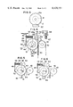
- FIG. 1 is a view in the direction of sheet movement, with some parts shown in section, showing the essential parts of one example of the detection device according to this invention
- FIG. 2 is a similar view of the same device in a state wherein two sheets in an overlapping state have been fed thereinto;
- FIG. 3 is a side view in the arrow direction III in FIG. 1 of a detecting device
- FIG. 4 is a side view, with some parts shown in section, showing the essential parts of another example of the detection device of the invention.
- FIG. 5 is a simplified side view of the device shown in FIG. 4 in the normal sheet feeding state.
- FIG. 6 is a simplified side view similar to FIG. 5 indicating the state of the device when two overlapping sheets have been fed thereinto.
- sheets P taken out one-by-one from a sheet storing section are conveyed to an overlapping feed detection device M by a device such as a conveying belt (not shown).
- This detection device M has a driving shaft 3 rotatably supported at its two ends by bearings 6, 6 on machine frame parts 1 and 2. At the middle part of this driving shaft 3, propelling rolls 4, 4 of the shape of rolls are formed integrally and coaxially with the shaft 3 at suitably spaced-apart positions. On both outer sides of these propelling rolls 4, 4, guide rings 5, 5 for guiding the two lateral sides of each sheet P are integrally formed with the driving shaft 3.
- a driven pulley 7 is fixedly mounted on one end (the left-hand end as viewed in FIGS. 1 and 2) of the driving shaft 3, which extends out beyond the left bearing 6.
- This driven pulley 7 is driven by an endless driving belt 8 passed therearound and driven by a driving power source (not shown).
- bearings 9, 9 are provided around the driving shaft 3.
- Each bearing 9 comprises an outer race 9a, an inner race 9b, and balls 9c interposed therebetween, the inner race 9b being coaxially fixed to the driving shaft 3.
- Each outer race 9a is prevented from rotating by a respective friction holding member 11 supported by a respective support arm 10 extending inward from the machine frame part 1 (or 2).
- a driven shaft 12 is disposed parallelly to the driving shaft 3 and is rotatably supported at its two ends by bearings 13, 13 on machine frame parts 1 and 2.
- the bearings 13, 13 are so supported on the frame parts 1 and 2 that they can be separated from or moved toward respective bearings 6, 6.
- the driven shaft 12 is provided with driven rolls 14, 14 formed integrally and coaxially therewith at spaced-apart positions in the axial direction to confront and be in register with the aforementioned propelling rolls 4, 4, respectively. Between each propelling roll 4 and its corresponding driven roll 14, a gate gap of a size such as to normally pass only a single sheet P is formed.
- the driven shaft 12 is further provided with pressing rollers 15, 15 disposed coaxially therewith at positions in the axial direction to confront and be in register with the aforementioned bearings 9, 9, respectively, on the driving shaft 3. These pressing rollers 15, 15 are in pressing contact with the outer surfaces of the outer races 9a, 9a of their respective bearings 9, 9.
- Each of the bearings 13, 13 rotatably supporting the driven shaft 12 at its ends is supported on one end of a compression spring 16 and is pressed thereby toward the corresponding bearing 6, whereby the driven shaft 12 is continually urged by these compression springs 16, 16 to move toward the driving shaft 3.
- the other ends of the compression springs 16 are secured to respective support frames 17, 17 fixedly supported on machine frame parts 19 and 20.
- a screw 18 fixed at one end thereof to each support frame 17 extends partly through the corresponding compression spring 16 and serves to limit the compressive deflection thereof.
- a detection disk 21 is fixed coaxially to the extreme right-hand end (as viewed in FIGS. 1 and 2) of the driven shaft 12, which extends outward beyond the right-hand bearing 13.
- this detection disk 21 is provided in a common circle near its outer periphery with numerous small through holes 21a formed at constant spacing intervals.
- the holes 21a are used in conjunction with a detector 22 to carry out detection as described hereinafter.
- the detection disk 21 and the detector 22 constitute a rotation detecting device 23.
- the detector 22 comprises a photosensor, which is positioned at the outer periphery of the detection disk 21 and detects the passing by of the holes 21a, transmitting a detection signal in response thereto to a counting circuit.
- the detector 22 may be adapted to operate cooperatively with a magnetic rotational member, or the detection disk may be provided with light-reflecting members for detection of rotation by utilizing reflected light.
- the example of the detection device of the above described construction according to this invention operates in the following manner.
- Sheets P taken out one at a time from a sheet storing section are successively fed by a conveyor belt or the like (also not shown) to the vicinity of the driving shaft 3. Then, since the driving shaft 3 is continually rotating, each sheet P passes through the gate gap between the propelling rolls 4, 4 and the driven rolls 14, 14 when the sheet P is not overlapped by another sheet. At this time, the pressing rollers 15, 15 of the driven shaft 12 are being caused by the compression springs 16, 16 to be in pressing contact with the outer races 9a, 9a of the bearings 9, 9. Moreover, since the outer races 9a, 9a are being held against rotation by the friction holding members 11, 11, the driven rolls 14, 14 do not rotate, and only one sheet passes through at one time in a normal manner.
- the driven rolls 14, 14 are immediately returned by the springs 16, 16 to their normal state wherein the aforementioned gate gap for a single sheet is restored and maintained between them and the propelling rolls 4, 4.
- the pressing rollers 15, 15 are immediately pressed against the corresponding outer races 9a, 9a of the bearings 9, 9 and are thereby immediately stopped. Consequently, the rotation of the detection disk 21 is stopped, and the counting of the holes 21a passing by the detector 22 is also stopped.
- the length of the overlapping parts of the two sheets P can be detected directly from the number of holes 21a counted, and the resulting detection signal can be utilized in an after process for appropriate measures. Moreover, this detection can be accomplished without the occurrence of the problem of signal waveform breakage or switch chattering, whereby the reliability of the device as an overlapping feed detection device can be remarkably elevated, and the number of rejected sheets in the case of rejection of overlapping sheet can be reduced to a minimum. Accordingly, a sheet-processing machine provided with the detection device of this invention can be made to operate with high efficiency.
- the conveying means for feeding sheets taken out one-by-one from a sheet storing section comprises conveying belts 40 and 41.
- One conveying belt 40 is passed around a propelling roll 43 which is fixedly mounted on a pulley shaft 42 and so disposed relative to a driven roll 44 that their peripheral surfaces confront each other.
- the driven roll 44 is rotatably mounted by a shaft 47 on a support member 46 at an intermediate part thereof.
- the support member 46 is essentially a lever which is pivotally supported at its one end by a pivot shaft 45 on a machine frame part (not shown) and is therefore free to swing about the pivot shaft 45.
- the driven roll 44 is continually urged to move toward the propelling roll 43 by a coil compression spring 50 in pressing contact at its one end (right-hand end as viewed in FIG. 4) against the other, free end of the support member 46 on the side thereof remote from the propelling roll 43.
- the other end of the compression spring 50 is in abutting contact against an intermediate part of a leaf spring 48 of cantilever type whose fixed end is fixed to a machine frame part.
- the compression spring 50 is stably supported by a screw 49 fixed at its head end to the leaf spring 48 and extending partly through the interior of the coil spring 50 toward the free end of the support member 46.
- the screw 49 further functions as a member for limiting movement, its other, free end 49a limiting the compressive deflection of the compression spring 50 when the support member swings in the counterclockwise direction (as viewed in FIG. 4) through an angle in excess of a specific angle and causing the leaf spring 48 to deflect leftward.
- a detection disk 51 having numerous holes 51a disposed at specific spacing intervals on and around a common circle near the outer periphery of the detection disk 51 for the purpose of detecting the quantity (angle) of rotation thereof. These holes 51a function cooperatively with a detector 52 described hereinafter to constitute and operate as a rotation detecting device 53.
- a stopping member 54 is normally in pressing contact against the outer peripheral surface of the driven roll 44 at the upper-right part thereof as viewed in FIG. 4.
- This stopping member 54 which is of the shape of a roller and is made of a material of large coefficient of friction, is fixedly supported on one end of an adjusting lever 56 pivotally supported at an intermediate part thereof by a pivot pin 55 on a machine frame part (not shown).
- the other end of the adjusting lever 56 is provided with an adjusting screw 57 screw-engaged therewith and having a tip in abutting contact with a datum surface 58 provided on a machine frame part.
- the head of the screw 57 is urged downwardly by a spring 57a to fix it in an adjusting position.
- the position of the stopping member 54 relative to the driven roll 44 is thus finely adjustable by the adjusting screw 57.
- the stopping member 54 thus sets the approaching position of the driven roll 44 relative to the propelling roll 43. In this normal state of these parts, the stopping member 54 functions to stop the rotation of the driven roll 44 and to cause a gate gap for permitting the passage therethrough of only a single sheet P to be formed between the driven roll 44 and the propelling roll 43.
- the second example of the detecting device of the above described construction according to this invention is adjusted and operates in the following manner.
- the gate gap between the propelling roll 43 and the driven roll 44 is adjusted to a value which is greater than the thickness of one sheet but less than that of two sheets to be processed.
- the sheets P taken out sheet-by-sheet from the sheet storing section are conveyed in the arrow direction shown in FIG. 4 between the conveying belts 40 and 41.
- the sheets P are thus arriving one-by-one, they pass normally through the gap between the propelling roll 43 and the driven roll 44 as shown in FIG. 5.
- the driven roll 44 is not rotating because the stopping member 54 is in pressing contact therewith, and it may be considered that a single sheet is being passed at one time in the normal manner.
- the detection device will operate as follows.
- the driven roll 44 is pressed toward the left, as viewed in FIG. 6, away from the propelling roll 43, and the support member 46, on which the driven roll 44 is rotatably supported, is caused to swing in the counterclockwise direction about its pivot shaft 45 counter to the rightward force of the compression spring 50. Consequently, the driven roll 44 separates from the stopping member 54 and thereby assumes a freely rotatable state, being rotated in the arrow direction, or counterclockwise direction, in FIG. 6.
- the detector 52 of the rotation detecting device 53 detects the movement of the holes 51a of the detection disk 51 and transmits a corresponding detection signal to a counting circuit (not shown).
- the output of the counting circuit indicates the length of overlap of the two overlapping sheets P,P and is utilized in an after treatment.
Abstract
Description
Claims (5)
Priority Applications (1)
| Application Number | Priority Date | Filing Date | Title |
|---|---|---|---|
| US06/293,261 US4420151A (en) | 1981-08-17 | 1981-08-17 | Overlapping feed detection device in sheet-processing machine |
Applications Claiming Priority (1)
| Application Number | Priority Date | Filing Date | Title |
|---|---|---|---|
| US06/293,261 US4420151A (en) | 1981-08-17 | 1981-08-17 | Overlapping feed detection device in sheet-processing machine |
Publications (1)
| Publication Number | Publication Date |
|---|---|
| US4420151A true US4420151A (en) | 1983-12-13 |
Family
ID=23128374
Family Applications (1)
| Application Number | Title | Priority Date | Filing Date |
|---|---|---|---|
| US06/293,261 Expired - Lifetime US4420151A (en) | 1981-08-17 | 1981-08-17 | Overlapping feed detection device in sheet-processing machine |
Country Status (1)
| Country | Link |
|---|---|
| US (1) | US4420151A (en) |
Cited By (18)
| Publication number | Priority date | Publication date | Assignee | Title |
|---|---|---|---|---|
| US4549826A (en) * | 1983-06-01 | 1985-10-29 | Siemens Aktiengesellschaft | Paper feed apparatus for typewriters or business machines having a paper levelling gap disposed in the paper guidance channel |
| US4753433A (en) * | 1986-04-24 | 1988-06-28 | Heidelberger Druckmaschinen Ag | Device for monitoring imbricated sheets stream fed to printing machines |
| US4938468A (en) * | 1985-10-24 | 1990-07-03 | Xerox Corporation | Non-rotating paper path idler |
| US4940224A (en) * | 1988-03-23 | 1990-07-10 | Unisys Corporation | Multiple document detector and separator |
| US5029845A (en) * | 1988-04-14 | 1991-07-09 | De La Rue Systems, Ltd. | Sheet feeding apparatus |
| US5129642A (en) * | 1988-06-02 | 1992-07-14 | Bell & Howell Company | Controllable document drive and separation system |
| US5143366A (en) * | 1990-09-07 | 1992-09-01 | Bell & Howell Company | Mail feeder |
| US5181715A (en) * | 1989-12-15 | 1993-01-26 | Canon Kabushiki Kaisha | Sheet conveying unit and system using the same |
| US5224695A (en) * | 1992-04-21 | 1993-07-06 | Bell & Howell Company | Method and apparatus for feeding documents |
| US5384468A (en) * | 1993-07-22 | 1995-01-24 | Ncr Corporation | Apparatus and method for indicating the thickness of record media by forcing a spaced roller into engagement with a pulse generator |
| US5813668A (en) * | 1994-03-31 | 1998-09-29 | Stielow Gmbh & Co. | Apparatus for conveying and staggering envelope contents for review by an operator |
| WO2001003857A1 (en) * | 1999-07-08 | 2001-01-18 | INA Wälzlager Schaeffler oHG | Transport device |
| US20010035603A1 (en) * | 2000-02-08 | 2001-11-01 | Graves Bradford T. | Method and apparatus for detecting doubled bills in a currency handling device |
| US20020060423A1 (en) * | 2000-11-17 | 2002-05-23 | Fuji Photo Film Co., Ltd. | Sheet conveyor system |
| US20050117010A1 (en) * | 2003-09-02 | 2005-06-02 | Seiko Epson Corporation | Medium transporting device and recording apparatus incorporating with the same |
| US20060163803A1 (en) * | 2005-01-26 | 2006-07-27 | Brother Kogyo Kabushiki Kaisha | Feeding Device And Image Recording Apparatus Equipped With The Feeding Device |
| US20090278307A1 (en) * | 2006-06-28 | 2009-11-12 | De La Rue International Limited | Document handling apparatus |
| US20100072696A1 (en) * | 2008-09-25 | 2010-03-25 | Sung-Po Cheng | Document processing apparatus with rotatable gap sensor |
Citations (7)
| Publication number | Priority date | Publication date | Assignee | Title |
|---|---|---|---|---|
| US567262A (en) * | 1896-09-08 | child | ||
| US2129230A (en) * | 1936-10-02 | 1938-09-06 | Continental Can Co | Double sheet ejector |
| US3130394A (en) * | 1959-12-07 | 1964-04-21 | Int Standard Electric Corp | Arrangement for detecting the stoppage of a movable body |
| US3354273A (en) * | 1965-09-24 | 1967-11-21 | Rca Corp | Two card detector |
| US4008891A (en) * | 1974-10-18 | 1977-02-22 | Transac-Compagnie Pour Le Development Des Transactions | Distributor of sheets in wads |
| US4050690A (en) * | 1976-09-16 | 1977-09-27 | Ncr Corporation | Document separator mechanism |
| US4203586A (en) * | 1978-06-28 | 1980-05-20 | Xerox Corporation | Multifeed detector |
-
1981
- 1981-08-17 US US06/293,261 patent/US4420151A/en not_active Expired - Lifetime
Patent Citations (7)
| Publication number | Priority date | Publication date | Assignee | Title |
|---|---|---|---|---|
| US567262A (en) * | 1896-09-08 | child | ||
| US2129230A (en) * | 1936-10-02 | 1938-09-06 | Continental Can Co | Double sheet ejector |
| US3130394A (en) * | 1959-12-07 | 1964-04-21 | Int Standard Electric Corp | Arrangement for detecting the stoppage of a movable body |
| US3354273A (en) * | 1965-09-24 | 1967-11-21 | Rca Corp | Two card detector |
| US4008891A (en) * | 1974-10-18 | 1977-02-22 | Transac-Compagnie Pour Le Development Des Transactions | Distributor of sheets in wads |
| US4050690A (en) * | 1976-09-16 | 1977-09-27 | Ncr Corporation | Document separator mechanism |
| US4203586A (en) * | 1978-06-28 | 1980-05-20 | Xerox Corporation | Multifeed detector |
Cited By (23)
| Publication number | Priority date | Publication date | Assignee | Title |
|---|---|---|---|---|
| US4549826A (en) * | 1983-06-01 | 1985-10-29 | Siemens Aktiengesellschaft | Paper feed apparatus for typewriters or business machines having a paper levelling gap disposed in the paper guidance channel |
| US4938468A (en) * | 1985-10-24 | 1990-07-03 | Xerox Corporation | Non-rotating paper path idler |
| US4753433A (en) * | 1986-04-24 | 1988-06-28 | Heidelberger Druckmaschinen Ag | Device for monitoring imbricated sheets stream fed to printing machines |
| US4940224A (en) * | 1988-03-23 | 1990-07-10 | Unisys Corporation | Multiple document detector and separator |
| US5029845A (en) * | 1988-04-14 | 1991-07-09 | De La Rue Systems, Ltd. | Sheet feeding apparatus |
| US5129642A (en) * | 1988-06-02 | 1992-07-14 | Bell & Howell Company | Controllable document drive and separation system |
| US5181715A (en) * | 1989-12-15 | 1993-01-26 | Canon Kabushiki Kaisha | Sheet conveying unit and system using the same |
| US5143366A (en) * | 1990-09-07 | 1992-09-01 | Bell & Howell Company | Mail feeder |
| US5224695A (en) * | 1992-04-21 | 1993-07-06 | Bell & Howell Company | Method and apparatus for feeding documents |
| US5384468A (en) * | 1993-07-22 | 1995-01-24 | Ncr Corporation | Apparatus and method for indicating the thickness of record media by forcing a spaced roller into engagement with a pulse generator |
| US5813668A (en) * | 1994-03-31 | 1998-09-29 | Stielow Gmbh & Co. | Apparatus for conveying and staggering envelope contents for review by an operator |
| WO2001003857A1 (en) * | 1999-07-08 | 2001-01-18 | INA Wälzlager Schaeffler oHG | Transport device |
| US20010035603A1 (en) * | 2000-02-08 | 2001-11-01 | Graves Bradford T. | Method and apparatus for detecting doubled bills in a currency handling device |
| US7103206B2 (en) | 2000-02-08 | 2006-09-05 | Cummins-Allison Corp. | Method and apparatus for detecting doubled bills in a currency handling device |
| US20020060423A1 (en) * | 2000-11-17 | 2002-05-23 | Fuji Photo Film Co., Ltd. | Sheet conveyor system |
| US6682069B2 (en) * | 2000-11-17 | 2004-01-27 | Fuji Photo Film Co., Ltd. | Sheet conveyor system |
| US20050117010A1 (en) * | 2003-09-02 | 2005-06-02 | Seiko Epson Corporation | Medium transporting device and recording apparatus incorporating with the same |
| US7517077B2 (en) * | 2003-09-02 | 2009-04-14 | Seiko Epson Corporation | Medium transporting device and recording apparatus incorporating with the same |
| US20060163803A1 (en) * | 2005-01-26 | 2006-07-27 | Brother Kogyo Kabushiki Kaisha | Feeding Device And Image Recording Apparatus Equipped With The Feeding Device |
| US7661674B2 (en) * | 2005-01-26 | 2010-02-16 | Brother Kogyo Kabushiki Kaisha | Feeding device and image recording apparatus equipped with the feeding device |
| US20090278307A1 (en) * | 2006-06-28 | 2009-11-12 | De La Rue International Limited | Document handling apparatus |
| US8052145B2 (en) * | 2006-06-28 | 2011-11-08 | De La Rue International Limited | Document handling apparatus |
| US20100072696A1 (en) * | 2008-09-25 | 2010-03-25 | Sung-Po Cheng | Document processing apparatus with rotatable gap sensor |
Similar Documents
| Publication | Publication Date | Title |
|---|---|---|
| US4420151A (en) | Overlapping feed detection device in sheet-processing machine | |
| EP2184242B1 (en) | Paper-sheet- thickness detecting device | |
| EP0130824B1 (en) | Sheet sensing apparatus | |
| US4687106A (en) | Letter-mail checking device | |
| US4050690A (en) | Document separator mechanism | |
| US5692743A (en) | Paper transport apparatus | |
| EP0514441A1 (en) | A method of, and apparatus for, delivering flat articles one by one from a stack of such articles. | |
| US5199702A (en) | Sheet transport apparatus | |
| EP0063159B1 (en) | Improvements in sheet handling machines | |
| EP2781479B1 (en) | Paper-sheet stacking apparatus | |
| FR2700529B1 (en) | Mail processing machine having a mechanical roller jogger. | |
| US4449399A (en) | Apparatus for detecting the passage of multiple superposed documents along a feed path | |
| US5456457A (en) | High speed separator with movable hold back belt for high speed flats feeder | |
| US3628787A (en) | Stacking device | |
| KR100564975B1 (en) | Sheets processing apparatus and sheets processing method | |
| US4941655A (en) | Skew-correcting and delay mechanism for sheet feeder | |
| EP0405466B1 (en) | Single sheet picking and transport mechanism | |
| JPS592033Y2 (en) | Duplicate feed detection device in paper sheet processing machines | |
| EP0098290B1 (en) | Apparatus for detecting the passage of multiple superposed documents along a feed path | |
| JPH0611992Y2 (en) | Paper thickness detection device | |
| US5115739A (en) | Document imprinting device having a rotation detector mounted on the print drum | |
| JP2761328B2 (en) | Paper sheet magnetic detector | |
| JPS6324517Y2 (en) | ||
| JPS62249830A (en) | Card separating feeder | |
| JPS59191688A (en) | Magnetism detector for sheet paper |
Legal Events
| Date | Code | Title | Description |
|---|---|---|---|
| AS | Assignment |
Owner name: GLORY KOGYO KABUSHIKI KAISHA 35, SHIMOTENO, HIMEJI Free format text: ASSIGNMENT OF ASSIGNORS INTEREST.;ASSIGNOR:KOBAYASHI, TETSUJI;REEL/FRAME:003908/0985 Effective date: 19810810 Owner name: GLORY KOGYO KABUSHIKI KAISHA 35, SHIMOTENO, HIMEJI Free format text: ASSIGNMENT OF ASSIGNORS INTEREST;ASSIGNOR:KOBAYASHI, TETSUJI;REEL/FRAME:003908/0985 Effective date: 19810810 |
|
| STCF | Information on status: patent grant |
Free format text: PATENTED CASE |
|
| MAFP | Maintenance fee payment |
Free format text: PAYMENT OF MAINTENANCE FEE, 4TH YEAR, PL 96-517 (ORIGINAL EVENT CODE: M170); ENTITY STATUS OF PATENT OWNER: LARGE ENTITY Year of fee payment: 4 |
|
| MAFP | Maintenance fee payment |
Free format text: PAYMENT OF MAINTENANCE FEE, 8TH YEAR, PL 96-517 (ORIGINAL EVENT CODE: M171); ENTITY STATUS OF PATENT OWNER: LARGE ENTITY Year of fee payment: 8 |
|
| FEPP | Fee payment procedure |
Free format text: PAYOR NUMBER ASSIGNED (ORIGINAL EVENT CODE: ASPN); ENTITY STATUS OF PATENT OWNER: LARGE ENTITY |
|
| MAFP | Maintenance fee payment |
Free format text: PAYMENT OF MAINTENANCE FEE, 12TH YEAR, LARGE ENTITY (ORIGINAL EVENT CODE: M185); ENTITY STATUS OF PATENT OWNER: LARGE ENTITY Year of fee payment: 12 |