US4368705A - Engine control system - Google Patents
Engine control system Download PDFInfo
- Publication number
- US4368705A US4368705A US06/277,745 US27774581A US4368705A US 4368705 A US4368705 A US 4368705A US 27774581 A US27774581 A US 27774581A US 4368705 A US4368705 A US 4368705A
- Authority
- US
- United States
- Prior art keywords
- engine
- signal
- fuel
- control
- signals
- Prior art date
- Legal status (The legal status is an assumption and is not a legal conclusion. Google has not performed a legal analysis and makes no representation as to the accuracy of the status listed.)
- Expired - Fee Related
Links
Images


Classifications
-
- F—MECHANICAL ENGINEERING; LIGHTING; HEATING; WEAPONS; BLASTING
- F02—COMBUSTION ENGINES; HOT-GAS OR COMBUSTION-PRODUCT ENGINE PLANTS
- F02D—CONTROLLING COMBUSTION ENGINES
- F02D41/00—Electrical control of supply of combustible mixture or its constituents
- F02D41/24—Electrical control of supply of combustible mixture or its constituents characterised by the use of digital means
- F02D41/2406—Electrical control of supply of combustible mixture or its constituents characterised by the use of digital means using essentially read only memories
- F02D41/2409—Addressing techniques specially adapted therefor
- F02D41/2422—Selective use of one or more tables
-
- F—MECHANICAL ENGINEERING; LIGHTING; HEATING; WEAPONS; BLASTING
- F02—COMBUSTION ENGINES; HOT-GAS OR COMBUSTION-PRODUCT ENGINE PLANTS
- F02D—CONTROLLING COMBUSTION ENGINES
- F02D41/00—Electrical control of supply of combustible mixture or its constituents
- F02D41/30—Controlling fuel injection
- F02D41/38—Controlling fuel injection of the high pressure type
- F02D41/40—Controlling fuel injection of the high pressure type with means for controlling injection timing or duration
- F02D41/401—Controlling injection timing
-
- F—MECHANICAL ENGINEERING; LIGHTING; HEATING; WEAPONS; BLASTING
- F02—COMBUSTION ENGINES; HOT-GAS OR COMBUSTION-PRODUCT ENGINE PLANTS
- F02B—INTERNAL-COMBUSTION PISTON ENGINES; COMBUSTION ENGINES IN GENERAL
- F02B1/00—Engines characterised by fuel-air mixture compression
- F02B1/02—Engines characterised by fuel-air mixture compression with positive ignition
- F02B1/04—Engines characterised by fuel-air mixture compression with positive ignition with fuel-air mixture admission into cylinder
-
- F—MECHANICAL ENGINEERING; LIGHTING; HEATING; WEAPONS; BLASTING
- F02—COMBUSTION ENGINES; HOT-GAS OR COMBUSTION-PRODUCT ENGINE PLANTS
- F02B—INTERNAL-COMBUSTION PISTON ENGINES; COMBUSTION ENGINES IN GENERAL
- F02B75/00—Other engines
- F02B75/02—Engines characterised by their cycles, e.g. six-stroke
- F02B2075/022—Engines characterised by their cycles, e.g. six-stroke having less than six strokes per cycle
- F02B2075/027—Engines characterised by their cycles, e.g. six-stroke having less than six strokes per cycle four
-
- F—MECHANICAL ENGINEERING; LIGHTING; HEATING; WEAPONS; BLASTING
- F02—COMBUSTION ENGINES; HOT-GAS OR COMBUSTION-PRODUCT ENGINE PLANTS
- F02B—INTERNAL-COMBUSTION PISTON ENGINES; COMBUSTION ENGINES IN GENERAL
- F02B3/00—Engines characterised by air compression and subsequent fuel addition
- F02B3/06—Engines characterised by air compression and subsequent fuel addition with compression ignition
-
- F—MECHANICAL ENGINEERING; LIGHTING; HEATING; WEAPONS; BLASTING
- F02—COMBUSTION ENGINES; HOT-GAS OR COMBUSTION-PRODUCT ENGINE PLANTS
- F02D—CONTROLLING COMBUSTION ENGINES
- F02D2200/00—Input parameters for engine control
- F02D2200/02—Input parameters for engine control the parameters being related to the engine
- F02D2200/04—Engine intake system parameters
- F02D2200/0406—Intake manifold pressure
-
- F—MECHANICAL ENGINEERING; LIGHTING; HEATING; WEAPONS; BLASTING
- F02—COMBUSTION ENGINES; HOT-GAS OR COMBUSTION-PRODUCT ENGINE PLANTS
- F02D—CONTROLLING COMBUSTION ENGINES
- F02D2200/00—Input parameters for engine control
- F02D2200/70—Input parameters for engine control said parameters being related to the vehicle exterior
- F02D2200/703—Atmospheric pressure
-
- F—MECHANICAL ENGINEERING; LIGHTING; HEATING; WEAPONS; BLASTING
- F02—COMBUSTION ENGINES; HOT-GAS OR COMBUSTION-PRODUCT ENGINE PLANTS
- F02D—CONTROLLING COMBUSTION ENGINES
- F02D41/00—Electrical control of supply of combustible mixture or its constituents
- F02D41/30—Controlling fuel injection
- F02D41/38—Controlling fuel injection of the high pressure type
- F02D41/40—Controlling fuel injection of the high pressure type with means for controlling injection timing or duration
- F02D41/406—Electrically controlling a diesel injection pump
- F02D41/407—Electrically controlling a diesel injection pump of the in-line type
-
- Y—GENERAL TAGGING OF NEW TECHNOLOGICAL DEVELOPMENTS; GENERAL TAGGING OF CROSS-SECTIONAL TECHNOLOGIES SPANNING OVER SEVERAL SECTIONS OF THE IPC; TECHNICAL SUBJECTS COVERED BY FORMER USPC CROSS-REFERENCE ART COLLECTIONS [XRACs] AND DIGESTS
- Y02—TECHNOLOGIES OR APPLICATIONS FOR MITIGATION OR ADAPTATION AGAINST CLIMATE CHANGE
- Y02T—CLIMATE CHANGE MITIGATION TECHNOLOGIES RELATED TO TRANSPORTATION
- Y02T10/00—Road transport of goods or passengers
- Y02T10/10—Internal combustion engine [ICE] based vehicles
- Y02T10/40—Engine management systems
Definitions
- This invention relates generally to diesel engines and more particularly to a control system for regulating the engine timing advance and the rack limit position of the fuel pump associated with the engine.
- the operation of a diesel engine is controlled basically by varying the amount of fuel delivered to the engine cylinders and by setting the time of fuel injection into the cylinders relative to the time that the pistons reach top dead center on their compression strokes.
- the amount of fuel delivered to the engine will control the speed of the engine and the timing of fuel injection will affect the efficiency of fuel combustion and engine operation. For example, if the engine speed increases, the timing advance angle of fuel injection must be increased to provide more time in a cycle of operation for compression, ignition and combustion of the injected fuel. If the timing advance is too great, however, ignition and combustion will occur too early in the cycle and the efficiency of operation will be adversely affected.
- a typical four-stroke-cycle diesel engine includes a timing shaft which is gear driven by the engine crank shaft at half engine speed, the timing shaft being coupled to the fuel camshaft of a fuel pump by a timing mechanism so that the fuel pump is engine driven and will deliver fuel to half of the engine cylinders during one engine revolution and to the other half of the cylinders during the next revolution.
- the fuel pump includes a movable, throttle-actuated fuel rack, under the control of the engine operation, to vary the amount of fuel delivered by the pump to the engine, up to the maximum amount permitted by the governor, or rack limit.
- the timing mechanism will vary the angular relationship between the rotating timing shaft and fuel camshaft to control the time of fuel injection into the cylinders.
- the Environmental Protection Agency has set Federal emission standards regulating the amount of smoke and gaseous emission which may be exhausted from an engine. Catalytic converters and exhaust gas recirculation have been used to reduce emission to acceptable levels, but at a significant reduction in fuel economy. It is preferable, as in the present invention, to control engine operation so that the fuel in the engine cylinders sufficiently burns and the exhaust components are within the required levels. To achieve the desired degree of combustion of the fuel-air mixture in the cylinders, a sufficient amount of air, relative to the amount of fuel in the mixture must be present for combustion and sufficient time must be allowed for the fuel to burn.
- the engine timing advance not be greater, nor the fuel rack limit be less, than that required to meet the emission standards.
- Timing and fuel rack for optimal performance.
- operation of the engine while cold will require settings of optimal timing advance for the many various combinations of engine speed and fuel rate which are different from the optimal timing advance for engine operation at normal running temperatures.
- Optimal timing advance for steady state running will differ between highway and urban operation. They will likewise differ when the engine is accelerating or decelerating.
- the optimal position of the rack limit for a given engine speed and timing will depend upon whether the engine is in a normal running or lugging mode and also upon the altitude at which the engine is operating.
- An engine control system must continuously monitor the actual speed of the engine and the actual timing advance to which the timing mechanism has set the fuel pump. In order to provide precise control over operation, the achieved speed and timing advance must be measured with precision and any changes in speed or timing angle must be noted with as small a lag time as possible. It is desirable to update the status of these monitored conditions many times during a single engine revolution, which introduces another problem in that inherent engine torsionals will cause the instantaneous engine speed to vary somewhat sinusoidally over two full revolutions of the engine. As a consequence it is necessary that the torsional variations in speed be cancelled to provide engine speed indications many times during an engine revolution, with each speed indication being that of the average speed of the engine.
- Microprocessors have come into use in various control system to store programmed information and to process such information quickly and reliably in response to sensed conditions so that control functions may be carried out.
- level of sophistication of operation of such systems seems limited only by the amount of money one is willing to spend on the system and, of course, by the inventiveness of the system designers.
- the present invention is directed to overcoming one or more of the problems set forth above.
- an engine-fuel supply system has an internal combustion engine and a fuel pump driven by the engine.
- the fuel pump has a movable fuel rack for controlling the amount of fuel delivered to the engine.
- a first settable engine control means has a timing means for driving the fuel pump at a desired timing advance angle relative to engine rotation, and a second settable engine control means has a rack limit means for limiting movement of the fuel rack in its fuel-increasing direction.
- a control system is provided having first and second condition signal means for monitoring first and second conditions of engine operation and a control signal means for storing a plurality of engine control signals.
- Each engine control signal has a predetermined value corresponding to a desired setting of one of the settable engine control means for desired operation at a particular combination of first and second engine conditions and for generating an engine control signal having the predetermined value for the monitored engine conditions.
- Means is provided for receiving the generated engine control signal and setting the one settable engine control means in response to said received signal.
- a further aspect of the invention is that separate control signal means as described above are used to control the engine timing means and the rack limit means.
- Another aspect of the invention is that a plurality of separate control signal means, as described above, are programmed for desired timing angle advance relative to different combinations of actual engine speed and fuel rack positions for a particular mode of engine operation.
- Selector means select the proper control signal means in accordance with the particular mode in which the engine is operating, deliver the selected control signal to actuate the timing means, and set the engine timing to the desired value for the existing actual speed and fuel rack position.
- the fuel delivery rate, used to set the rack limit is determined by obtaining the optimal fuel/air ratio for the particular speed and timing advance angle of the engine and by multiplying such fuel/air ratio by the manifold pressure to obtain a value proportional to the maximum amount of fuel to be injected into an engine cylinder.
- Another aspect of the invention is that in the control system, instantaneous engine speed signals are measured a plurality of times for each revolution of the engine, and each time an instantaneous speed signal is obtained, the instantaneous speed signals obtained during the past two engine revolutions are averaged to cancel out the effect of engine torsionals so that an average speed signal is obtained a plurality of times for each revolution of the engine.
- Yet another aspect of the invention is that digital condition and control signals in binary form are used in the control system and that an interpolation method is used in the control signal means to obtain the predetermined control signals by reading a programmed memory in accordance with the most significant bits of the control signal, and by interpolating between adjacent programmed signals in accordance with the least significant bits of the control signals.
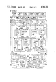
- FIG. 1 is a block diagram of an engine-fuel pump system and a control system therefor utilizing the present invention
- FIG. 2 is a block diagram of one of the control signal means of FIG. 1, and in particular, the cold engine timing map;
- FIG. 3 is a three dimensional graph illustrating the memory portion of the map of FIG. 2;
- FIGS. 4 and 5 illustrate the three-dimensional schedules of the fuel/air limit and rack limit position maps of FIG. 1;
- FIG. 6 is a block diagram of one of the two-dimensional maps of FIG. 1 and in particular, the transient timing map;
- FIGS. 7 and 8 illustrate the two-dimensional schedules of the altitude derating and torque rise limit maps of FIG. 1;
- FIG. 9 is a block diagram of the timing map selector of FIG. 1;
- FIG. 10 is a generally schematic view of the physical components of the engine fuel system of FIG. 1 and the sensors used therewith for sensing engine speed and timing advance angle;
- FIG. 11 is a graph illustrating the effect of engine torsionals
- FIG. 12 is a graph illustrating the torsional cancellation technique by which average engine speed signals are obtained for use in the present invention.
- FIG. 13 is a block diagram of one form of the data processors of FIG. 10;
- FIG. 14 is a timing chart of the signals produced by the flywheel and fuel camshaft sensors of FIG. 10 and used in the data processor of FIG. 13;
- FIG. 15 is a modification of a portion of the data processor of FIG. 13;
- FIG. 16 is block diagram of an alternate form of the data processor of FIG. 10;
- FIG. 17 is a timing chart of the signals produced by the flywheel and fuel camshaft sensors of FIG. 10 and used in the data processor of FIG. 16.
- FIG. 1 shows in block diagram form a control system 10 for use with internal combustion engine 11.
- the engine 11 which may be a four-stroke-cycle diesel engine, drives a timing shaft 12 which is coupled, by engine timing means 13, to the fuel camshaft 14 of fuel pump 16.
- timing means 13 will set a minimum phase shift between the timing shaft 12 and fuel camshaft 14 so that fuel pump 16 will deliver fuel from fuel tank 17 to the cylinders of engine 11 at a minimum advance angle, typically 14° BTDC, on the compression stroke of the engine pistons.
- Actuation of the timing means 13 by a timing actuator 18 will vary the timing of fuel delivery between minimum and maximum advance angles.
- the fuel pump 16 has a movable fuel rack 21, actuated by an operator-controllable throttle, such as foot pedal 22, to control the amount of fuel delivered by fuel pump 16 to the engine 11.
- an operator-controllable throttle such as foot pedal 22
- depression of the foot pedal 22 will move the fuel rack 21 to the left to increase fuel delivery.
- Release of the foot pedal will move fuel rack 21 to the right, decreasing fuel delivery.
- a reciprocatable rack limit 23, functioning as a governor, will prevent leftward (fuel increasing) movement of fuel rack 21 beyond the limit set by rack limit actuator 24, even though the operator may be then demanding a greater fuel flow by depression of foot pedal 22.
- Rack limit 23 allows rightward movement of fuel rack 21 from the limit position so that the operator may control fuel delivery by foot pedal 22 between minimum fuel delivery and the maximum set by rack limit 23.
- the timing means 13 and fuel rack limit 23 constitute first and second settable engine control means which are themselves controlled by the control system 10 of the present invention.
- This control system 10 has two primary functions. First, the control system 10 functions to cause timing actuator 18 to adjust the engine timing means 13 and thereby set the proper engine timing advance angle for efficient combustion. Second, it functions to cause rack limit actuator 24 to move rack limit 23 and set it to limit the maximum amount of fuel which the fuel pump can deliver to the engine cylinders.
- the following conditions of engine operation are continuously monitored and used in the control system 10 to set the engine timing and rack limit position: actual engine timing, engine temperature, throttle position, fuel rack position, actual engine speed, atmospheric pressure and intake manifold pressure.
- a timing sensor 26 continuously monitors the magnitude of the actual timing advance angle set by engine timing means 13 and generates a condition signal having a value dependent upon the magnitude of the timing advance.
- This condition signal is shaped and prescaled by signal conditioner 27, converted from a frequency signal to a digital signal by frequency/digital converter 28 and applied to input line 29 of microprocessor 30.
- the actual timing information is updated every 30° or 60° of engine rotation, depending upon the particular embodiment of the sensor system used. This will be described subsequently in connection with FIGS. 10-17.
- the engine temperature is monitored, as for example by a conventional analog sensor 31 which senses the temperature of the engine coolant, to determine whether the engine is cold, as on start-up, or whether it has reached normal running condition.
- the condition signal from the engine temperature sensor 31 is shaped and prescaled by conditioner 32, converted from analog to digital form by converter 33, and applied to microprocessor input line 34.
- Throttle position is monitored by sensor 36, which may include a potentiometer linked to foot pedal 22, to determine whether the operator has called for acceleration by a depression of the pedal or deceleration by a release of the pedal.
- sensor 36 which may include a potentiometer linked to foot pedal 22, to determine whether the operator has called for acceleration by a depression of the pedal or deceleration by a release of the pedal.
- rack position sensor 37 which may include a potentiometer linked to the fuel rack 21, to provide information as to the amount of fuel being delivered by fuel pump 16 to engine 11.
- Actual engine speed is continuously monitored by the engine speed sensor 38. As will be described hereinafter, new actual engine speed signals are generated every 30° or 60° of engine rotation, depending upon the particular sensor system used, so that the engine control system 10 will respond very quickly to changes in the engine speed.
- Atmospheric pressure and intake manifold pressure are monitored by conventional pressure transducers 39 and 40, respectively.
- the operating condition signals from sensors 36-40 are likewise shaped and prescaled by signal conditioners 32, converted to digital form by converters 41-45, analog-digital or frequency-digital, depending upon the nature of the condition signals, and applied to input lines 46-50 of the microprocessor 30.
- the microprocessor 30 will respond to the condition signals of the aforementioned sensors 31,36,37,38,39,40 and will output engine control signals to set the engine timing and rack limit to desired and predetermined positions.
- the microprocessor 30 includes a plurality of "maps" for controlling engine timing and rack position.
- the various maps described below each constitute a control signal means for storing a plurality of engine control signals, with each stored control signal having a predetermined value corresponding to a desired setting of one of the settable engine control means 13 or 23 for desired operation at a particular combination of engine operating conditions, and for generating an engine control signal having the predetermined value corresponding to the particular value of the engine operating conditions as indicated by the engine condition signals.
- microprocessor 30 includes four maps, 61,62,63 and 64 which are used to control the engine timing.
- the "cold engine map" 61 will have stored within its read-only memory 61a (FIG. 2) a plurality of predetermined engine timing control signals for various combinations of actual engine speed and rack position.
- the values of the timing control signals are determined empirically for an engine family by carrying out tests on a cold engine (of that family) and compiling a schedule of the optimum values of engine timing for various combinations of engine speed and rack position which will enable the engine to operate with its exhaust to meet the EPA emission standards. After this engine timing schedule has been completed, the values are programmed into the various cells of read-only memory 61a.
- the actual speed and rack position condition signals are applied to map 61 during operation of the vehicle, and the map will output, to timing map selector 65 an engine control signal having the desired value, for the existing speed and fuel rack positions which will set the timing means 13 for engine operation meeting the EPA emission standards.
- the "transient timing map" 62 will have stored therewithin the proper timing angle values for different engine speeds, such values again having been determined by testing for efficient engine operation when the engine is accelerating or decelerating.
- the actual engine speed signals are applied to the map with corresponding engine timing angle signals being output to selector 65.
- the "steady state urban timing map” 63 and “steady state highway timing map” 64 are similar to the cold engine timing map 61 in that maps 63 and 64 have stored therewithin the proper engine timing value for each combination of engine speed and rack position, such values again being predetermined to meet EPA standards for urban and highway driving, respectively. Also, as before, the particular timing angle values for the existing engine speed and rack position are output to map selector 65.
- Map selector 65 functions to determine which of the following modes what of engine operation exists: cold, transient, steady state urban or steady state highway; and to allow the timing angle control signals at the output of the correct one of the maps 61-64 to pass to summing junction 66. If the timing angle control signals indicate that the engine timing should be changed, summing junction 66 will output a signal to a pulse width modulator 67 and a power amplifier 68 will then drive the timing actuator 18 so that the engine timing means 13 will change the engine timing to the desired timing advance angle between timing shaft 12 and fuel camshaft 14.
- the timing sensor 26 senses the engine timing an provides a signal which, after processing by the signal conditioner 27 and frequency to digital converter 28, is output to the microprocessor input line 29. The signal is then fed to summing junction 66 so that the output of the summing junction 66 will cease when the actual engine timing equals the desired engine timing.
- fuel flow must be related to air flow through the engine so that sufficient air is provided for substantially complete fuel combustion.
- the fuel/air ratio for a given smoke level will vary with engine speed. To prevent engine lugging, more fuel must be injected, but with the fuel/air ratio being controlled to maintain efficient fuel combustion.
- During acceleration or deceleration it is desired for the engine 11 to produce maximum power within acceptable smoke limits. Operation at high altitudes requires a decrease in fuel delivery to maintain the proper fuel/air ratio for proper combustion.
- the rate of air flow through the engine will vary with the manifold pressure and the rate of fuel flow will vary with the position of fuel rack 21.
- the maps 71,72,73 and 74 of microprocessor 30 are used in the present system to set the position of rack limit 23 and thereby limit the amount of movement of fuel rack 21 in its fuel-increasing direction so that the engine operator cannot cause the fuel injection rate and consequently the fuel/air ratio to increase beyond that which will produce an acceptable amount of smoke in the engine exhaust.
- the "fuel/air limit map" 71 has programmed therein predetermined values, established by empirical testing, corresponding to the maximum fuel/air ratio for sufficient combustion to meet EPA standards for various different combinations of engine speed and timing within the operating ranges of those conditions.
- map 71 will output a fuel/air signal proportional to the maximum amount of fuel to amount of air of the mixture to be injected into the engine during a stroke thereof for the then existing timing angle and engine speed.
- the fuel/air output signal of map 71 is applied to multiplier 76, along with the condition signal from the intake manifold pressure sensor 40, the latter signal being proportional to the intake pressure, for example, in pounds per square inch gauge. Since the weight of air injected into the engine cylinders with the fuel is proportional to the manifold pressure, multiplier 76 will output a signal proportional to the maximum weight of fuel to be injected during a stroke thereof.
- multiplier 76 The output of multiplier 76 is then multiplied in multiplier 77 by K F , a dimensional constant dependent upon the cylinder size and fuel pump size of the particular engine 11 and fuel pump 16, to give a fuel-delivery signal proportional to the maximum weight of fuel to be delivered to the engine 11 during a piston stroke thereof.
- the fuel-delivery signal from multiplier 77 is input into "rack limit position map” 72, which has stored therewithin rack limit position values, predetermined in accordance with the physical characteristics of the fuel pump 16. These correspond to the positions at which the rack limit 23 is to be set to give the desired rate of fuel delivery at the existing engine (and hence fuel pump) speed.
- the rack limit position control signals from map 72 are output to map selector 78.
- the "torque rise limit map” 73 is provided to increase the rack limit position and thereby allow the fuel rack 21 to move in a fuel-increasing direction in such mode of operation and thereby prevent engine lugging.
- the torque rise limit map 73 has stored therein rack limit position control signal values, predetermined to allow more fuel to be injected at lower speeds without causing emissions exceeding the EPA standards.
- the rack limit position control signals generated by map 73 in response to application of engine speed signals thereto are applied through summing junction 79 to selector 78.
- the "altitude derating map” 74 has stored therewithin rack limit position control signal values, predetermined to meet EPA standards, for different values of ambient air pressure.
- the output of map 74 is applied to summing junction 79 which functions to decrease the value of the rack limit position control signal and thus cut back the fuel rack 21 at higher altitudes to maintain an optimal fuel/air ratio.
- Map selector 78 functions as a "least win logic" so that the lowest value of the rack limit position control signals from map 72 and the signal from summing junction 79 is output to summing junction 81. If such control signal indicates that the position of rack limit 23 is to be changed, summing junction 81 will output a signal to pulse width modulator 82 and power amplifier 83 will then drive the rack limit actuator 24 to cause the desired movement of rack limit 23.
- rack limit sensor 84 which may include a potentiometer coupled to the rack limit 23, and the signal therefrom is conditioned and prescaled by signal conditioner 85, converted to digital form by converter 86 and fed back to the summing junction 81 so that the rack limit actuator 24 will cease to be driven when the actual rack limit position is the same as the desired rack limit position.
- FIGS. 2 and 3 illustrate the manner in which an engine timing control signal from the cold engine timing map 61 is obtained for a particular combination of actual engine speed and rack position.
- map includes a read-only memory and the input and output circuitry of the memory.
- the input line 47 into microprocessor 30 has an eight-bit binary signal, or byte, thereon from rack position sensor 37 representing the actual position of fuel rack 21.
- the signal will have been prescaled to the range of rack movement so that the 256 possible combinations of the byte represent the corresponding number of incremental positions of the rack between its minimum and maximum position.
- input line 48 will have a byte thereon, the particular binary value of which will represent a particular engine speed within the range of minimum and maximum operating speeds.
- the cold engine timing map 61 includes a read-only memory 61a having a three-dimensional schedule with 16 rows and 16 columns, and with a Z-value byte stored within the memory for each combination of a row and column.
- the 256 bytes stored in the memory are determined, for the family of engine with which the control system is to be used, through testing to represent the correct timing angle advance for the various possible combinations of rack position and engine speed which will meet EPA standards. If the byte values for the timing angle signal were plotted graphically, the scheduled byte values would lie on a three-dimensional surface 91, at the intersection of the 16 rows thereon corresponding to different values of rack position and the 16 columns corresponding to the different values of actual engine speed.
- the rack position signal on line 47 and the actual engine speed signal on line 48 will be updated at most each time the engine 11 rotates through 30°, and the binary values of these signals will remain constant between updates.
- the four most significant bits (X 1 ) of the rack position signal on input line 47 will be applied to row selector 101, and the four most significant bits (Y 1 ) of the engine speed signal on input line 48 will be applied to column selector 102 to select the particular row (X 1 ) and column (Y 1 ) of memory 61a.
- the Z 1 byte (FIG. 4) corresponding to the X 1 row and Y 1 column is outputted from memory 61a and Z output selector 103 to the Z 1 memory 104.
- the X 1 bits are also applied to stepper 106 which adds a binary 1 to the X 1 value and the stepped (X 1 +1) bits are then applied to row selector 101, while the Y 1 bits are applied to column selector 102, to select the (X 1 +1) row and Y 1 column.
- the Z 2 byte for the (X 1 +1) row and Y 1 column is then stored into the Z 2 memory 107.
- stepper 108 the (Y 1 +1) value from stepper 108 and the X 1 value are applied to the map and the corresponding Z 3 byte is stored in the Z 3 memory 109. Subsequently, the (X 1 +1) bits and (Y 1 +1) bits are applied to the map 61 and the corresponding Z 4 byte is stored in the Z 4 memory 110.
- the value of Z a is an interpolated value between the values Z 1 and Z 2 for Y 1 and corresponding to the degree of difference between X 1 and X 1 +1 represented by the x 1 value of the rack position byte.
- function generator 112 will produce an interpolated Z b byte having a value between the Z 3 and Z 4 bytes (for Y 1 +1).
- Za and Zb bytes will be applied to function generator 113 which produces a Zo byte, ##EQU2##
- Z o is an interpolated value between the values Z a and Z b (for Y 1 +Y 1 ) corresponding to the degree of difference between Y 1 and (Y 1 +1) represented by the y 1 value of the actual engine speed byte.
- the interpolated Z o byte is then stored in memory, or latch, 114 for use in the control system 10 until the time that the rack position and engine speed input information has been next updated and a new Z o signal has been calculated.
- timing advance angle byte corresponding to particular rack position and engine speed bytes
- memory utilization is only about 400 bytes
- accuracy is 0.4%
- execution speed is about 800 microseconds.
- the steady state urban timing map 63 and steady state highway timing map 64 are three dimensional maps generally similar to the cold engine timing map of FIGS. 2 and 3. Interpolated values of timing advance control signals are obtained from these maps 63,64 in the same manner as that previously detailed for the cold engine timing map 61. Maps 63 and 64 differ from the cold engine maps 62, and from each other, only in the specific desired timing angle control signal that is, the z-valve-stored within the memory cells of these maps for the various combinations of rack position and engine speed. Again, the values of the stored bytes in maps 63 and 64 are determined for an engine family to meet EPA standards for urban or highway driving respectively.
- the read-only memories 71a and 72a of fuel/air limit map 71 and rack limit position map 72 are generally illustrated in FIGS. 4 and 5, respectively.
- these are three dimensional memories with predetermined bytes stored therein, and interpolated byte signals are obtained therefrom in the same way as described above.
- the memory 71a of fuel/air limit map 71 has stored bytes corresponding to the optimal fuel/air ratio for different combinations of engine speed and the actual timing angle.
- the memory 72a of rack limit position map 72 has stored therewith byte values which will represent the limit position of rack 21 to deliver the desired amount of fuel at a particular engine speed.
- the transient timing map 62 of FIG. 6, includes a two-dimensional read-only memory 62a, having 16 rows and 16 possible control signal bytes for each particular row.
- the four most significant bits (X 1 ) of the engine speed byte on input line 48 are applied to the row selector 101 to select the proper row of map 62, and the corresponding Y 1 byte stored in the output is sent to the Y 1 memory 116.
- Stepper 106 adds a binary 1 to X 1 , and the (X 1 +1) binary bits are applied to the row selector to select the next, (X 1 +1), row and the corresponding (Y 1 +1) byte is outputted to the (Y 1 +1) memory 117.
- the Y 1 and (Y 1 +1) bytes are then applied to function generator 118, along with the least significant bits x 1 of the engine speed byte to obtain a calculated and interpolated Y o byte corresponding to the particular engine speed byte on input line 48.
- the Y o timing advance angle byte is then sent broadside to a Y o memory or latch 119 for use in controlling the timing means 13 until the next Y o byte is calculated.
- the memory portion 74a of the altitude derating map 74 is illustrated in FIG. 7 and has stored therewithin rack position bytes for different values of barometric pressure. As will be noted, the values of the stored rack limit position control signals decrease, as at 121, for low values of barometric pressure.
- the purpose for the altitude derating map 74 in the present control system is to cut back the rack (by a lower value rack limit position control signal) at higher altitudes so as to provide an optimal air-fuel ratio.
- the values stored within the map 74 are predetermined to meet EPA standards.
- the memory portion 73a at the torque rise limit map 73 is illustrated in FIG. 8, and has stored therewithin rack limit position control data, in byte form, for different values of engine speed. As previously mentioned, when engine speed decreases due to load the rack will inherently move to provide more fuel to the engine, and the torque rise table will limit such movement so that exhaust emissions will be held to proper limits.
- the dotted line 122 in FIG. 8 shows the correction that will be imposed under lugging conditions by the rack cut-back of altitude derating map 74 at high elevations.
- FIG. 9 illustrates a form of selector 65 which may be used to determine which of the timing maps 61-64 is to be used to control the timing advance angle of the engine 11.
- the engine temperature signal from the engine temperature sensor 31 is applied to gate control 131.
- the engine temperature sensor 31 will output a low temperature value causing gate control 131 to close gate 132, allowing the timing advance angle control signal from the cold engine timing map 61 to pass through to the output 133 of selector 65.
- Gates 134,135 and 136 will be held open, so that the outputs of maps 62,63 and 64 will be prevented from appearing at the selector output 133.
- gate control 131 will open gate 132 to disconnect the cold engine timing map 61 from the selector output and will close gates 134-136 to allow the appropriate map 62,63 or 64 to control the timing advance angle.
- the throttle position signal from sensor 36 is applied to gate control 137.
- the throttle position signal will be generated by sensor 36 only when the operator has substantially depressed the pedal for acceleration or substantially released the pedal for deceleration.
- gate control 137 will go Q causing gate 138 to close, connecting the transient timing map 62 to the selector output 133 (if the engine is at normal operating temperature) and will cause gates 139 and 140 to open so that the steady state maps 63 and 64 cannot control the timing advance angle.
- the throttle position signal ceases (i.e.
- gate control 137 when the operator ceases calling for significant acceleration or deceleration) gate control 137 will open gate 138 to disconnect the transient timing map 62 from the selector output 133 and will close gates 139 and 140 to enable the timing advance angle to be controlled by one or the other of the steady state maps 63 or 64.
- the throttle-position signal is also applied to the urban condition detector 142 together with the signal from a differentiator 143.
- the engine speed signal from the engine speed sensor 38 is applied to differentiator 143 which will output on engine-speed-change signal in response to changes in engine speed.
- the urban condition detector 142 functions to generate a signal upon a concurrence of the throttle position signal and an engine-speed-change signal from differentiator 143, i.e. when the operator is calling for acceleration and the engine speed is increasing, or when the operator is calling for deceleration and the engine speed is slowing.
- the signals from detector 142 are applied to counter 144 and if the count of such signals reaches a predetermined number before the counter 144 is reset by timer 145, the Q output of counter 144 will set the gate control 146 so that its Q output will close gate 147 to connect the steady state urban timing map 63 to selector output 133 (provided that gates 139 and 134 are also closed.)
- counter 144 After being reset, counter 144 will again count the signals from urban condition detector. As long as the number of such signals during the period of timer 145 remains above the predetermined number, gate control 146 will remain set and the steady state urban timing map 63 will remain connected to selector output 133. If, however, the count of signals from detector 143 does not exceed the predetermined number by the time of the reset signal from timer 145, the reset signal and the Q output of counter 144 will cause AND gate 148 to reset gate control 146. Gate 147 will open and the Q output of gate control 146 will cause gate 149 to close, connecting the steady state highway timing map 64 to the selector output 132.
- the time period of timer 145 and the number of signals from detector 142 needed to set gate control 146 are chosen to distinguish between driving conditions which occur in urban or highway driving.
- Urban driving requires frequent accelerations or decelerations because of stop signs, heavy traffic and the like.
- Highway driving on the other hand, will require only occasional accelerations or decelerations, as when another vehicle is being passed.
- the engine speed will decrease or increase without change in throttle positions, such as when the vehicle goes up or down grades, but such changes in engine speed will not cause the urban condition detector 142 to output a signal to counter 144 since a throttle position signal is concurrently required for such detector signal.
- FIG. 10 illustrates portions of interest of a conventional engine and fuel system.
- a crank shaft 211 of engine 11 has a flywheel 212 fixed thereon and meshed gears 213 and 214, on crank shaft 211 and timing shaft 12, respectively, transmit engine rotation to the timing shaft 12.
- gear ratio of gears 213 and 214 is such that the timing shaft 12 is driven at half the speed of the engine 11.
- Timing means 13 rotatively drives fuel camshaft 14 of fuel pump 16 by the timing shaft 12 and is arranged to vary, within a predetermined range, the angular relationship between the timing shaft 12 and fuel camshaft 14 so that fuel is delivered to the engine cylinders at the proper time in the cycle of engine operation.
- timing means 13 may comprise a differential assembly. The system may be initially set to deliver fuel from fuel tank 17 and fuel line 233 to the engine 11 at a minimum advance (typically 14°) before top dead center of the engine pistons.
- the timing advance actuator 18 means will cause the timing means 13 to set the advance angle of fuel delivery at a desired value greater than minimum during operation of the engine 11, as by actuation of solenoid valve 234 in response to the output of amplifier 68.
- the timing advance means will cause the fuel camshaft 14 to be driven at the same speed as that of timing shaft 12, but the angular relationship of the two shafts will be varied from the minimum advance relationship to provide the correct timing for the given conditions.
- the fuel pump 16 has a movable fuel rack 21, which controls the amount of fuel flowing through the fuel pump 16. As mentioned previously, the fuel rack 21 is moved in response to foot pedal 22, and its movement is limited by fuel rack limit 23. Fuel rack limit 23 may be the piston of hydraulic cylinder 241, with piston movement being controlled by actuation of solenoid valve 242 in response to the output of amplifier 83.
- a first rotation responsive means 246 is provided for generating a signal each successive time that engine 11 has rotated through 360/N degrees, N being an integer.
- the rotation responsive means 246 includes a plurality of holes 247 in flywheel 212, equi-angularly spaced relative to, and equi-distantly spaced from the axis of the flywheel. Holes 247 thus provide surface irregularities on the ferromagnetic flywheel 212 which constitute magnetically-sensible features which rotate in a circular path around the crank shaft 211.
- the first rotation responsive means 246 may be associated with gear 214 on the timing shaft 12, gear 214 be provided with 24 holes 247.
- Rotation responsive means 246 also includes a first signal generating means 248 for generating a first signal 249 (FIG. 14) in response to each movement of a flywheel hole 247 past a predetermined point in the circular path of movement of holes 247.
- the signal generating means 248 includes a fixed magnetic sensor 250 located adjacent the circular path of movement, the location of the sensor 250 thus determining the predetermined point in the path of movement of holes 247.
- flywheel 212 has twelve holes 247 and thus a first signal 249 will be generated each time the engine rotates through 360/12, or 30 degrees. Since timing shaft 12 is driven at half the engine speed, a first signal will be generated each time the timing shaft rotates through 15 degrees.
- a second rotation responsive means 251 is provided for generating a second signal each successive time that the engine has rotated through 360/N degrees.
- the rotation responsive means 251 fixed to fuel camshaft 14 for rotation therewith, circular member 252 having a plurality of holes 253 equi-angularly spaced around member 223 and all at the same distance from the axis of camshaft 14.
- holes 253 provide magnetically-sensible, surface irregularity features which move in a circular path around camshaft 14.
- Rotation responsive means 251 also includes a second signal generating means 254 for generating a second signal 255 (FIG. 14) in response to each movement of a hole 253 past a predetermined point in the circular path of movement of holes 253.
- the signal generating means 254 includes a fixed magnetic sensor 256 located adjacent the circular path of movement of holes 253. Again, the fixed location of sensor 256 determines the predetermined point in the path of movement of holes 253.
- circular member 252 has twenty-four holes 253, and thus a second signal 255 will be generated for each 15 degrees of rotation of camshaft 14. Or, since fuel camshaft 14 is driven at half engine speed, a second signal 225 will be generated for each 30 degrees of rotation of engine 10.
- the number of first signals 249 from the flywheel sensor 250 will be equal to the number of second signals 225 from the fuel camshaft sensor 256 during any given length of time, such as the time that it takes the engine crank shaft 211, or the time that it takes either of the timing or fuel camshaft 12 or 14 to rotate through a full revolution, and the time interval between consecutive first signals 249 will be equal to the time interval between consecutive second signals 258.
- the phase relationship of the first and second signals 249 and 255 will vary in accordance with the timing advance angle set by the timing means 13.
- the first and second signals from the flywheel sensor 250 and fuel camshaft sensor 256 are then sent to the data processor 260 wherein the signals are used to generate digital signals proportional to the engine speed and the timing advance angle of the fuel pump.
- the engine speed and timing advance angle signals are also generated in a manner so as to cancel out the effect of engine torsionals.
- Piston-operated internal-combustion engines have inherent imbalances which cause regularly occurring disturbances in the operation of the engine. Since one-half of the pistons drive the crank shaft 211 during one complete engine revolution and the other one-half of the pistons drive the crank shaft 211 during the subsequent revolution, and since these two sequences have a discrete set of disturbances associated with them, the two revolutions will never have precisely the same characteristics. The crank shaft 211 will always have a somewhat different amount of power transmitted to it during one full revolution than the one immediately preceding or following.
- the inherent engine imbalances will produce a half order torsional having a full cycle during two full engine revolutions, a first order torsional occurring in one full engine revolution, a second order torsional occurring in one-half an engine revolution, and so on with higher order torsionals of decreasing magnitude.
- the result of the torsionals is that the instantaneous engine speed will vary as the engine rotates.
- the mass of the drive system and flywheel will dampen the effect of the imbalances but the actual speed will still vary sinusoidally through two engine revolutions, with the engine alternately accelerating and decelerating.
- the instantaneous speed of the engine 11 is determined N/M times for each full revolution of the engine, N being an integer representing the number of times that a signal from the flywheel sensor 249 is generated during a full engine revolution, and M being either 1 or 2, depending upon whether a new, updated speed determination is made each time a flywheel sensor signal 249 is generated or whether a new, updated speed determination is made for every other flywheel sensor signal 249.
- N/M consecutive instantaneous speed determinations are then added and divided by (N/M)P, P being an integer representing a number of full engine revolutions, to obtain an average engine speed during the P number of engine revolutions.
- FIG. 13 illustrates one embodiment of data processor 260 which can be used to generate average speed and average timing advance angle signals in response to generation of signals by the flywheel and fuel camshaft sensors 250 and 256.
- flywheel sensor 250 will generate a series of first signals 249 in response to each passage of a flywheel hole 247 therepast, with a time lapse of T 1 between consecutive leading edges of the signals.
- the fuel camshaft sensor 256 will likewise generate a series of second signals 255, each also having a time lapse of T 1 , between consecutive signals.
- the first and second signals 249 and 255 will be out of phase with each other in an amount dependent upon the position of the timing means 13, and there will be a time lapse of T 2 between the leading edge of a second singal 255 and the leading edge of the next successive first signal 249.
- the time lapse T 1 is inversely proportional to engine speed--the faster the speed of engine rotation, the shorter the time of T 1 and vice versa.
- the time lapse T 2 for any given phase relation between the timing and fuel camshaft 12 and 14 is also inversely proportional to engine speed.
- the ratio of T 2 /T 1 is proportional to the degree of phase relation between the timing and fuel camshafts 12 and 14, and will remain constant for any given degree of phase relation regardless of engine speed.
- a fixed frequency clock 265 generates a continuous series of high frequency clock pulses which are applied to the inputs of the T 1 gate 266 and the T 2 gate 267.
- the first signal 249 from the flywheel sensor 250 is applied to flip-flop 268 so that a low Q flip-flop output from alternate first signals 249 will cause the T 1 gate 266 to close and a high Q flip-flop output from the next successive first signal 249 will cause the T 1 gate 266 to open.
- the T 1 pulse counter 269 will have a count of the number of clock pulses occurring during the time interval beginning and ending with successive first signals 249. Since clock 265 has a fixed frequency, the count of the T 1 pulse counter 269 will be inversely proportional to the speed of the engine.
- the count T 1 (t), i.e. the instantaneous count for 30° of engine revolution, in the T 1 counter is applied to divider 271, along with a constant K R , the divider 271 functioning to divide the constant K R by the count T 1 (t) and serving as a speed-indicating means for generating an instantaneous speed-indicating signal, SPD(t), which is inversely proportional to the count T 1 (t) of the counter 266 and is thus directly proportional to the instantaneous engine speed measured during the time the T 1 gate 266 was closed.
- the constant K R is chosen to scale the T 1 (t) count so that a useful eight-bit binary coded SPD(t) signal is obtained by divider 271.
- the SPD(t) signal is then applied to the input cell of shift register 272, the shift register having NP/M number of cells.
- shift register 272 would have 12 cells.
- the successively generated speed-indicating signals SPD(t) will be applied to shift register 272 so that the shift register will have, at any time, the 12 most recent successive speed-indicating signals therein.
- the signals in all of the shift register cells are applied to the speed averaging means 273, shown here as an adder-divider, which adds the NP/M number of speed-indicating signals and divides the sum by NP/M to generate an average speed signal.
- the adder-divider 273 outputs the average speed signal into the 8-bit memory, or latch 74 which stores such signal until the next average speed signal is generated.
- the 8-bit or byte, signal is applied to input line 48 of microprocessor 30 and used as an input to the four timing maps 61-64, the fuel/air limit map 71, the torque rise limit map 73 and the rack limit position map 72.
- the engine speed signal is also applied to differentiator 143 which controls the function of the timing map selector 65.
- the Q output of flip-flop 268 is also applied to AND gate 276 to enable the next successive second signal 255 from the fuel camshaft sensor 256 to close the T 2 gate 267.
- the T 2 gate 267 will be opened in response to the same first signal 249 which opens the T 1 gate 266.
- the T 2 counter 277 will count clock pulses passing through gate 267 and will thus obtain a count of the number of clock pulses occurring in the time interval beginning with a second signal 255 and ending with the next successive first signal 249.
- the gates 266 and 267 and pulse counters 269 and 277 constitute a counting means 278 for counting clock pulses occurring in the time interval T 1 beginning and ending with consecutive first signal 249 from the pulse generating means 248 and for counting clock pulses occurring in the time interval T 2 beginning with a second signal 255 from pulse generating means 251 and ending with the next successive first signal 249 from pulse generating means 248.
- the timing means 13 When the engine is first started, the timing means 13 will be a minimum advance, e.g. 14° BTDC, and there will be an initial angular phase relation between the timing and fuel camshafts 12 and 14 to cause fuel delivery to the engine with minimum advance. Likewise, there will be an initial phase relation between the first signals 249 from the flywheel sensor 250 and the second signal 255 from the fuel camshaft sensor 256, corresponding to minimum advance, with a second signal 256 preceding the next successive first signal 255 by a particular degree of rotation. It is an aspect of the present embodiment that the circular member 252 on the fuel camshaft 14 can be randomly fixed thereto, without regard to whether its holes 253 have any particular orientation with respect to the holes 247 of the flywheel.
- the engine will initially operate at minimum advance angle.
- Dividing one count by the other gives a signal which is proportional to the degree of engine rotation between a second signal 255 and the next succeeding first signal 249 relative to the degree of engine rotation between consecutive first signals 249. Such signal is thus independent of engine speed.
- the constant K T scales that divided counts to provide a useful binary coded signal, with the constant K T also representing the angle that the engine turns between successive first signals.
- the initial timing advance angle signal TIM(o) is then stored for use in the data processor 260 until the engine is shut down.
- 30° of engine rotation are required to develop the counts in counters 269 and 277 and a new timing advance signal TIM(t) will be generated in the next 30° of engine rotation. Accordingly, six new timing advance signals TIM(t) will be generated for each full engine revolution.
- the initial and instantaneous timing advance signals TIM(o) and TIM(t) are applied to logic circuit 281. If the magnitude of the instantaneous timing advance signal TIM(t) is not less than the magnitude of the initial timing advance signal TIM(o), function generator 282 will subtract the initial timing advance signal TIM(o) from the instantaneous timing advance signal TIM(t) which is proportional to the actual degree of timing advance produced by the timing means 13.
- function generator 283 will add the angle K T to the instantaneous timing advance signal TIM(t) and then subtract the initial timing advance signal TIM(o) therefrom to generate a positive true timing signal TIM(t) to which is proportional to the actual angle of advance from minimum advance.
- the successive true timing advance signals TIM(T) are entered into and advanced through the NP/M cell shift register 284. Each time a new TIM(T) signal is entered into shift register 284, the TIM(T) signals in the shift register cells are applied to adder-divider 285 which functions as an angle-averaging means for generating an average timing angle advance signal. Such signal is output into the 8-bit memory 286, or latch, which stores the signal until the next average timing advance angle signal is generated.
- the byte in memory 286 is applied to input line 29 of microprocessor 30 and used as an input to the fuel/air limit map 71.
- FIG. 15 illustrates a modification of the system of FIG. 14, which may be used in an engine system wherein the timing advance means 13 is physically constrained so that a maximum timing advance of 20° from minimum advance is obtainable.
- the TIM(o) and TIM(t) timing advance angle signals are applied to the TIM(o) 10° and TIM(t) 10° logic circuits 281a and 281b and the function generators 282 and 283 are actuated in accordance with the logic circuits to generate the desired true timing advance signals TIM(T).
- the circular member 252 may be randomly fixed on the fuel camshaft 14, but the average speed and average timing advance signals will be updated only six times for each full engine revolution.
- the circular member 252 must be more accurately located on the fuel camshaft 14 (or the fixed location of the fixed sensors 249 and/or 255 must be more accurately chosen) so that at minimum timing advance a particular second signal 255 is generated slightly before a particular first signal 249 and at maximum timing advance such second signal is generated before the same first signal 249 but after the preceding first signal 249.
- the circular member 252 should be oriented on the fuel camshaft 14 so that, at minimum timing advance angle, a second signal 255 will be generated somewhere between one and nine degrees in advance of a first signal 249.
- the data processor 260a of FIG. 16 differs from that of FIG. 13 in that each second signal 255 from the fuel camshaft sensor 256 is used to close the T 2 gate 267, with the gate being opened by the next first signal 249 from the flywheel sensor 250.
- a new count by the T 2 counter 277 of the clock pulses from the fixed frequency clock 265 is obtained each time the engine rotates through 30°, or, twelve times during a full engine rotation.
- the data processor 260a also differs in that gate 266 is closed by each first signal 249 from the flywheel sensor 250 and is opened by the next occurring second signal 255 from the fuel camshaft sensor 256.
- the clock pulses during this period are then counted by the T 3 counter 269a, with the count being proportional to the length of this time period.
- the T 3 count is sent to adder 269b, enabling the T 3 counter 269a to be reset.
- the time periods T 2 +T 3 will always equal the time period T 1 .
- gates 266 and 267, pulse counters 269a and 277 and adder 269b constitute counting means 278 for counting clock pulses occurring in the time interval T 1 beginning and ending with consecutive first signals from the pulse generating means 248 and for counting clock pulses occurring in the time interval T 2 beginning with a second signal 255 from pulse generating means 251 and ending with the next successive first-signal 249 from pulse generating means 248.
- the T 1 signal from adder 269b, generated for each 30° of engine revolution, is then sent to divider 271, and an average speed indicating signal is generated by the shift register 272 (with 24 cells) and adder-divider 273 as before.
- 24 instantaneous speed indicating signals will be averaged for two full engine revolutions and a new average speed indicating signal will be generated for each successive 30° of engine revolution.
- the T 1 signal from adder 269b and the T 2 signal from counter 277 will also be applied, as before, to dividers 279 and 280 wherein an initial timing advance signal TIM(o) and subsequent instantaneous timing advance signals TIM(t) are generated.
- the TIM(T) signals are sent successively to 24-cell shift register 284 and the 24 signals occurring during two full revolutions of the engine are averaged by adder-divider 285 and latched into the 8-bit memory, or latch 286, once for each successive 30° of engine rotation.
- control system 10 of the present invention provides an integrated and automatic regulation of engine timing and maximum allowable fuel rate so that maximum engine performance can be realized, in its various modes of operation, while limiting smoke and emissions to required levels.
- the disclosed control system is particularly useful with four-stroke-cycle diesel engines used in highway trucks.
- a system such as that described could be used to automatically regulate features of an engine other than the timing and maximum permissible fuel delivery.
Abstract
Description
Claims (26)
Priority Applications (2)
| Application Number | Priority Date | Filing Date | Title |
|---|---|---|---|
| US06/277,745 US4368705A (en) | 1981-03-03 | 1981-03-03 | Engine control system |
| CA000390114A CA1167548A (en) | 1981-03-03 | 1981-11-16 | Engine control system |
Applications Claiming Priority (1)
| Application Number | Priority Date | Filing Date | Title |
|---|---|---|---|
| US06/277,745 US4368705A (en) | 1981-03-03 | 1981-03-03 | Engine control system |
Publications (1)
| Publication Number | Publication Date |
|---|---|
| US4368705A true US4368705A (en) | 1983-01-18 |
Family
ID=23062177
Family Applications (1)
| Application Number | Title | Priority Date | Filing Date |
|---|---|---|---|
| US06/277,745 Expired - Fee Related US4368705A (en) | 1981-03-03 | 1981-03-03 | Engine control system |
Country Status (2)
| Country | Link |
|---|---|
| US (1) | US4368705A (en) |
| CA (1) | CA1167548A (en) |
Cited By (85)
| Publication number | Priority date | Publication date | Assignee | Title |
|---|---|---|---|---|
| US4401076A (en) * | 1981-04-20 | 1983-08-30 | Hitachi, Ltd. | Fuel injection control system for electromagnetic valve-controlled fuel injection pump of diesel engine |
| US4432322A (en) * | 1981-08-01 | 1984-02-21 | Nippondenso Co., Ltd. | Method and system for controlling ignition timing in a multicylinder internal combustion engine |
| US4450817A (en) * | 1981-03-19 | 1984-05-29 | Nippondenso Co., Ltd. | Method and apparatus for controlling fuel injection timing for compression ignition engines |
| US4467764A (en) * | 1982-04-07 | 1984-08-28 | Nippondenso Co., Ltd. | Method and apparatus for controlling ignition timing in a multicylinder internal combustion engine |
| US4483294A (en) * | 1981-03-05 | 1984-11-20 | Nissan Motor Company, Limited | Engine control system |
| US4487181A (en) * | 1982-04-03 | 1984-12-11 | Lucas Industries Public Limited Company | Fuel supply system for an internal combustion engine |
| US4496286A (en) * | 1983-07-18 | 1985-01-29 | J-W Operating Company | Control system for engine-driven compressor unit and method of operation thereof |
| US4497301A (en) * | 1981-02-20 | 1985-02-05 | Honda Giken Kogyo Kabushiki Kaisha | Electronic fuel injection control system for internal combustion engines, including means for detecting engine operating condition parameters |
| US4502437A (en) * | 1981-11-02 | 1985-03-05 | Ambac Industries, Incorporated | Electrical fuel control system and method for diesel engines |
| US4558679A (en) * | 1980-11-07 | 1985-12-17 | Sanwa Seiki Mfg., Co., Ltd. | Method of controlling hydraulic actuator |
| US4566414A (en) * | 1981-04-11 | 1986-01-28 | Robert Bosch Gmbh | Control system for an internal combustion engine |
| US4572132A (en) * | 1982-02-11 | 1986-02-25 | Robert Bosch Gmbh | Electronic control system for a diesel injection system of an internal combustion engine |
| US4596221A (en) * | 1985-06-24 | 1986-06-24 | General Motors Corporation | Transient injection timing control |
| US4597368A (en) * | 1985-02-25 | 1986-07-01 | General Motors Corporation | Engine idle speed control system |
| US4601270A (en) * | 1983-12-27 | 1986-07-22 | United Technologies Diesel Systems, Inc. | Method and apparatus for torque control of an internal combustion engine as a function of exhaust smoke level |
| US4619234A (en) * | 1984-07-03 | 1986-10-28 | Diesel Kiki Co., Ltd. | Electronically controlled fuel injection apparatus |
| US4625700A (en) * | 1981-02-13 | 1986-12-02 | Elsbett L | Plunger pump for delivering liquids especially fuels, for reciprocating internal combustion engines |
| US4642773A (en) * | 1983-07-08 | 1987-02-10 | Nippondenso Co., Ltd. | Method and apparatus for controlling an engine |
| US4643154A (en) * | 1984-08-27 | 1987-02-17 | Toyota Jidosha Kabushiki Kaisha | Method of and device for controlling fuel injection timing in diesel engine |
| US4690114A (en) * | 1984-08-11 | 1987-09-01 | Robert Bosch Gmbh | Speed governing system for a fuel injected internal combustion engine, especially a diesel engine |
| US4708112A (en) * | 1985-07-11 | 1987-11-24 | Kokusan Denki Co. Ltd. | Electronic governor for an internal combustion engine |
| US4715339A (en) * | 1984-09-01 | 1987-12-29 | Kawasaki Jukogyo Kabushiki Kaisha | Governor for internal combustion engine |
| US4726342A (en) * | 1986-06-30 | 1988-02-23 | Kwik Products International Corp. | Fuel-air ratio (lambda) correcting apparatus for a rotor-type carburetor for integral combustion engines |
| US4729358A (en) * | 1986-04-09 | 1988-03-08 | Hitachi, Ltd. | Engine controlling system |
| US4736726A (en) * | 1985-07-18 | 1988-04-12 | Toyota Jidosha Kabushiki Kaisha | Method and system for controlling fuel ignition timing in diesel engine |
| US4790277A (en) * | 1987-06-03 | 1988-12-13 | Ford Motor Company | Self-adjusting fuel injection system |
| US4869850A (en) * | 1986-06-30 | 1989-09-26 | Kwik Products International Corporation | Rotor-type carburetor apparatus and associated methods |
| WO1990001115A1 (en) * | 1988-07-22 | 1990-02-08 | Caterpillar Inc. | Engine cruise control with variable power limits |
| US5019986A (en) * | 1990-04-27 | 1991-05-28 | Caterpillar Inc. | Method of operating a vehicle engine |
| US5086739A (en) * | 1989-04-06 | 1992-02-11 | Daimler-Benz Ag | Electronic speed governor for an air-compression internal-combustion engine |
| USRE33929E (en) * | 1982-05-28 | 1992-05-19 | Kwik Products International Corporation | Central injection device for internal combustion engines |
| US5117790A (en) * | 1991-02-19 | 1992-06-02 | Caterpillar Inc. | Engine operation using fully flexible valve and injection events |
| US5176123A (en) * | 1991-06-05 | 1993-01-05 | Honda Giken Kogyo Kabushiki Kaisha | Evaporative fuel-purging control system for internal combustion engines |
| US5201296A (en) * | 1992-03-30 | 1993-04-13 | Caterpillar Inc. | Control system for an internal combustion engine |
| US5205152A (en) * | 1991-02-19 | 1993-04-27 | Caterpillar Inc. | Engine operation and testing using fully flexible valve and injection events |
| US5268842A (en) * | 1990-12-03 | 1993-12-07 | Cummins Engine Company, Inc. | Electronic control of engine fuel injection based on engine duty cycle |
| US5357912A (en) * | 1993-02-26 | 1994-10-25 | Caterpillar Inc. | Electronic control system and method for a hydraulically-actuated fuel injection system |
| US5365904A (en) * | 1993-07-23 | 1994-11-22 | Caterpillar Inc. | Redundant speed sensor for engine control |
| US5375577A (en) * | 1993-07-23 | 1994-12-27 | Caterpillar Inc. | Apparatus and method for controlling engine response versus exhaust smoke |
| US5377112A (en) * | 1991-12-19 | 1994-12-27 | Caterpillar Inc. | Method for diagnosing an engine using computer based models |
| US5445129A (en) * | 1994-07-29 | 1995-08-29 | Caterpillar Inc. | Method for controlling a hydraulically-actuated fuel injection system |
| US5447138A (en) * | 1994-07-29 | 1995-09-05 | Caterpillar, Inc. | Method for controlling a hydraulically-actuated fuel injections system to start an engine |
| US5477828A (en) * | 1994-07-29 | 1995-12-26 | Caterpillar Inc. | Method for controlling a hydraulically-actuated fuel injection system |
| US5494018A (en) * | 1994-10-28 | 1996-02-27 | General Motors Corporation | Altitude dependent fuel injection timing |
| US5526266A (en) * | 1991-12-19 | 1996-06-11 | Caterpillar Inc. | Method for diagnosing an engine using a computer based boost pressure model |
| US5529044A (en) * | 1994-07-29 | 1996-06-25 | Caterpillar Inc. | Method for controlling the fuel injection rate of a hydraulically-actuated fuel injection system |
| EP0457757B1 (en) * | 1989-02-10 | 1996-09-25 | IMPERIAL, Renzo | Device for varying the angular relationship between the crankshaft and the camshaft of an internal combustion engine |
| US5585553A (en) * | 1995-07-28 | 1996-12-17 | Caterpillar Inc. | Apparatus and method for diagnosing an engine using a boost pressure model |
| US5600558A (en) * | 1994-08-12 | 1997-02-04 | Caterpillar Inc. | Data exception reporting system |
| US5604306A (en) * | 1995-07-28 | 1997-02-18 | Caterpillar Inc. | Apparatus and method for detecting a plugged air filter on an engine |
| US5609126A (en) * | 1994-10-03 | 1997-03-11 | Ford Motor Company | Variable camshaft timing system with altitude compensation |
| US5642284A (en) * | 1994-08-12 | 1997-06-24 | Caterpillar Inc. | Maintenance monitor system |
| US5646341A (en) * | 1995-07-28 | 1997-07-08 | Caterpillar Inc. | Apparatus and method for diagnosing an engine using an oil pressure model |
| US5738070A (en) * | 1996-12-11 | 1998-04-14 | Caterpillar Inc. | Method and apparatus for operation of a speed-governed lean burn engine to improve load response |
| US5771857A (en) * | 1996-11-06 | 1998-06-30 | Caterpillar Inc. | Direct injected gas engine with variable gas pressure control apparatus and method of operation |
| US5813374A (en) * | 1987-11-12 | 1998-09-29 | Injection Research Specialists, Inc. | Two-cycle engine with electronic fuel injection |
| US5857159A (en) * | 1994-08-12 | 1999-01-05 | Caterpillar Inc. | Data recording and display system |
| US5873248A (en) * | 1996-06-21 | 1999-02-23 | Caterpillar Inc. | Turbocharger control system |
| US5983156A (en) * | 1997-09-03 | 1999-11-09 | Cummins Engine Company | System for controlling engine fueling according to vehicle location |
| US6016788A (en) * | 1997-07-18 | 2000-01-25 | Toyota Jidosha Kabushiki Kaisha | Fuel injection control system for a diesel engine |
| EP0987425A1 (en) * | 1998-09-09 | 2000-03-22 | Mazda Motor Corporation | Control system for diesel engine |
| US6148801A (en) * | 1996-09-13 | 2000-11-21 | Siemens Aktiengesellschaft | Method for controlling a fuel quantity to be fed to an internal combustion engine and engine control device operating according to the method |
| US6152107A (en) * | 1998-08-24 | 2000-11-28 | Caterpillar Inc. | Device for controlling fuel injection in cold engine temperatures |
| US6367456B1 (en) | 1994-07-29 | 2002-04-09 | Caterpillar Inc. | Method of determining the fuel injection timing for an internal combustion engine |
| US6397821B1 (en) * | 1999-08-06 | 2002-06-04 | Mtu Friedrichshafen Gmbh | Method and device for controlling an internal combustion engine |
| US6470849B1 (en) | 2001-06-26 | 2002-10-29 | Caterpillar Inc. | Separate injector main timing maps for use with and without pilot |
| US20030109977A1 (en) * | 2001-12-06 | 2003-06-12 | Landes James W. | Method and apparatus for parasitic load compensation |
| US6760659B1 (en) | 2002-11-26 | 2004-07-06 | Controls, Inc. | Device and method for engine control |
| US6842689B2 (en) | 2002-05-15 | 2005-01-11 | Caterpillar Inc | System for dynamically controlling power provided by an engine |
| US20050049819A1 (en) * | 2003-09-03 | 2005-03-03 | Longnecker John Edward | Method and system for controlling engine temperature by engine derating |
| EP1617054A1 (en) * | 2003-04-14 | 2006-01-18 | Yanmar Co., Ltd. | Control mechanism for fuel injection pump |
| US20070100536A1 (en) * | 2005-10-31 | 2007-05-03 | Caterpillar Inc. | System for controlling fuel delivery at altitude |
| US20080047245A1 (en) * | 2006-08-24 | 2008-02-28 | Macgregor Don | Tractor with two engine settings |
| US7340339B1 (en) * | 2003-02-14 | 2008-03-04 | Caterpillar Inc. | Power management system |
| US20090133670A1 (en) * | 2006-05-09 | 2009-05-28 | Yanmar Co., Ltd. | Cold Start Device for Fuel Injection Pump |
| US20100088436A1 (en) * | 2007-08-16 | 2010-04-08 | Matthias Knauss | Communication method and interface between a companion chip and a microcontroller |
| US7775043B2 (en) | 2006-05-31 | 2010-08-17 | Caterpillar Inc | Turbocharger control system |
| US20110174242A1 (en) * | 2010-04-09 | 2011-07-21 | Mcconahay Fred E | Cylindrical hydrogen fuel generator having tubular cells with microscopic indentations |
| US20120185151A1 (en) * | 2011-01-19 | 2012-07-19 | GM Global Technology Operations LLC | System and method for controlling fuel injection to decrease particulate emissions during transient engine operation |
| US20130066541A1 (en) * | 2010-03-30 | 2013-03-14 | Harald Schueler | Starter device, interface device, and method for operating a system of a starter device |
| WO2014001767A1 (en) * | 2012-06-27 | 2014-01-03 | Perkins Engines Company Limited | Method of controlling fuel to be injected within a combustion engine |
| US20150345418A1 (en) * | 2012-12-04 | 2015-12-03 | Volvo Truck Corporation | Method and system for controlling fuel injection |
| US20160222771A1 (en) * | 2013-10-15 | 2016-08-04 | Halliburton Energy Services, Inc. | Optimization of engine emissions from equipment used in well site operations |
| US10480441B2 (en) | 2015-07-22 | 2019-11-19 | Cummins Inc. | System and method for controlling exhaust gas temperature |
| US11566579B2 (en) * | 2017-10-03 | 2023-01-31 | Polaris Industries Inc. | Method and system for controlling an engine |
Citations (14)
| Publication number | Priority date | Publication date | Assignee | Title |
|---|---|---|---|---|
| US3699935A (en) * | 1969-12-13 | 1972-10-24 | Bosch Gmbh Robert | Fail-safe fuel injection control arrangement for internal combustion engines |
| US3796192A (en) * | 1971-10-14 | 1974-03-12 | A Parker | Method and apparatus for handling live poultry |
| US3815564A (en) * | 1971-03-06 | 1974-06-11 | Nippon Denso Co | Fuel injection device for internal combustion engines |
| US3960120A (en) * | 1974-06-21 | 1976-06-01 | Nisan Motor Co., Ltd. | Electronic fuel injection control circuit for an internal combustion engine |
| US3964443A (en) * | 1973-05-25 | 1976-06-22 | The Bendix Corporation | Digital engine control system using DDA schedule generators |
| US4019478A (en) * | 1972-07-25 | 1977-04-26 | Nippondenso Co., Ltd. | Fuel injection timing control system for internal combustion engine |
| US4048965A (en) * | 1974-12-05 | 1977-09-20 | Robert Bosch Gmbh | Apparatus for determining the fuel injection quantity in mixture compressing internal combustion engines |
| US4084240A (en) * | 1976-07-28 | 1978-04-11 | Chrysler Corporation | Mass production of electronic control units for engines |
| US4191137A (en) * | 1976-11-04 | 1980-03-04 | Lucas Industries Limited | Electronic fuel injection control for an internal combustion engine |
| US4205377A (en) * | 1977-04-22 | 1980-05-27 | Hitachi, Ltd. | Control system for internal combustion engine |
| US4212065A (en) * | 1978-06-22 | 1980-07-08 | The Bendix Corporation | Altitude compensation feature for electronic fuel management systems |
| US4217862A (en) * | 1977-03-28 | 1980-08-19 | Combustion Research & Technology, Inc. | High constant pressure, electronically controlled diesel fuel injection system |
| US4223654A (en) * | 1976-11-02 | 1980-09-23 | Robert Bosch Gmbh | Method and apparatus for controlling the operation of a diesel engine |
| US4265200A (en) * | 1976-11-23 | 1981-05-05 | Robert Bosch Gmbh | Method and apparatus for controlling the onset of fuel injection in diesel engines |
-
1981
- 1981-03-03 US US06/277,745 patent/US4368705A/en not_active Expired - Fee Related
- 1981-11-16 CA CA000390114A patent/CA1167548A/en not_active Expired
Patent Citations (15)
| Publication number | Priority date | Publication date | Assignee | Title |
|---|---|---|---|---|
| US3699935A (en) * | 1969-12-13 | 1972-10-24 | Bosch Gmbh Robert | Fail-safe fuel injection control arrangement for internal combustion engines |
| US3815564A (en) * | 1971-03-06 | 1974-06-11 | Nippon Denso Co | Fuel injection device for internal combustion engines |
| US3796192A (en) * | 1971-10-14 | 1974-03-12 | A Parker | Method and apparatus for handling live poultry |
| US4019478A (en) * | 1972-07-25 | 1977-04-26 | Nippondenso Co., Ltd. | Fuel injection timing control system for internal combustion engine |
| US3964443A (en) * | 1973-05-25 | 1976-06-22 | The Bendix Corporation | Digital engine control system using DDA schedule generators |
| US3960120A (en) * | 1974-06-21 | 1976-06-01 | Nisan Motor Co., Ltd. | Electronic fuel injection control circuit for an internal combustion engine |
| US4048965A (en) * | 1974-12-05 | 1977-09-20 | Robert Bosch Gmbh | Apparatus for determining the fuel injection quantity in mixture compressing internal combustion engines |
| US4084240A (en) * | 1976-07-28 | 1978-04-11 | Chrysler Corporation | Mass production of electronic control units for engines |
| US4128900A (en) * | 1976-07-28 | 1978-12-05 | Chrysler Corporation | Programmable read only memory for electronic engine control |
| US4223654A (en) * | 1976-11-02 | 1980-09-23 | Robert Bosch Gmbh | Method and apparatus for controlling the operation of a diesel engine |
| US4191137A (en) * | 1976-11-04 | 1980-03-04 | Lucas Industries Limited | Electronic fuel injection control for an internal combustion engine |
| US4265200A (en) * | 1976-11-23 | 1981-05-05 | Robert Bosch Gmbh | Method and apparatus for controlling the onset of fuel injection in diesel engines |
| US4217862A (en) * | 1977-03-28 | 1980-08-19 | Combustion Research & Technology, Inc. | High constant pressure, electronically controlled diesel fuel injection system |
| US4205377A (en) * | 1977-04-22 | 1980-05-27 | Hitachi, Ltd. | Control system for internal combustion engine |
| US4212065A (en) * | 1978-06-22 | 1980-07-08 | The Bendix Corporation | Altitude compensation feature for electronic fuel management systems |
Non-Patent Citations (1)
| Title |
|---|
| Research Disclosure Dated Nov. 1978. * |
Cited By (116)
| Publication number | Priority date | Publication date | Assignee | Title |
|---|---|---|---|---|
| US4558679A (en) * | 1980-11-07 | 1985-12-17 | Sanwa Seiki Mfg., Co., Ltd. | Method of controlling hydraulic actuator |
| US4625700A (en) * | 1981-02-13 | 1986-12-02 | Elsbett L | Plunger pump for delivering liquids especially fuels, for reciprocating internal combustion engines |
| US4497301A (en) * | 1981-02-20 | 1985-02-05 | Honda Giken Kogyo Kabushiki Kaisha | Electronic fuel injection control system for internal combustion engines, including means for detecting engine operating condition parameters |
| US4483294A (en) * | 1981-03-05 | 1984-11-20 | Nissan Motor Company, Limited | Engine control system |
| US4450817A (en) * | 1981-03-19 | 1984-05-29 | Nippondenso Co., Ltd. | Method and apparatus for controlling fuel injection timing for compression ignition engines |
| US4566414A (en) * | 1981-04-11 | 1986-01-28 | Robert Bosch Gmbh | Control system for an internal combustion engine |
| US4401076A (en) * | 1981-04-20 | 1983-08-30 | Hitachi, Ltd. | Fuel injection control system for electromagnetic valve-controlled fuel injection pump of diesel engine |
| US4432322A (en) * | 1981-08-01 | 1984-02-21 | Nippondenso Co., Ltd. | Method and system for controlling ignition timing in a multicylinder internal combustion engine |
| US4502437A (en) * | 1981-11-02 | 1985-03-05 | Ambac Industries, Incorporated | Electrical fuel control system and method for diesel engines |
| US4572132A (en) * | 1982-02-11 | 1986-02-25 | Robert Bosch Gmbh | Electronic control system for a diesel injection system of an internal combustion engine |
| US4487181A (en) * | 1982-04-03 | 1984-12-11 | Lucas Industries Public Limited Company | Fuel supply system for an internal combustion engine |
| US4467764A (en) * | 1982-04-07 | 1984-08-28 | Nippondenso Co., Ltd. | Method and apparatus for controlling ignition timing in a multicylinder internal combustion engine |
| USRE33929E (en) * | 1982-05-28 | 1992-05-19 | Kwik Products International Corporation | Central injection device for internal combustion engines |
| US4642773A (en) * | 1983-07-08 | 1987-02-10 | Nippondenso Co., Ltd. | Method and apparatus for controlling an engine |
| US4496286A (en) * | 1983-07-18 | 1985-01-29 | J-W Operating Company | Control system for engine-driven compressor unit and method of operation thereof |
| AU567324B2 (en) * | 1983-07-18 | 1987-11-19 | J-W Operating Co. | Control system for engine-driven compressor unit |
| US4601270A (en) * | 1983-12-27 | 1986-07-22 | United Technologies Diesel Systems, Inc. | Method and apparatus for torque control of an internal combustion engine as a function of exhaust smoke level |
| US4619234A (en) * | 1984-07-03 | 1986-10-28 | Diesel Kiki Co., Ltd. | Electronically controlled fuel injection apparatus |
| US4690114A (en) * | 1984-08-11 | 1987-09-01 | Robert Bosch Gmbh | Speed governing system for a fuel injected internal combustion engine, especially a diesel engine |
| US4643154A (en) * | 1984-08-27 | 1987-02-17 | Toyota Jidosha Kabushiki Kaisha | Method of and device for controlling fuel injection timing in diesel engine |
| US4715339A (en) * | 1984-09-01 | 1987-12-29 | Kawasaki Jukogyo Kabushiki Kaisha | Governor for internal combustion engine |
| US4597368A (en) * | 1985-02-25 | 1986-07-01 | General Motors Corporation | Engine idle speed control system |
| EP0206517A2 (en) * | 1985-06-24 | 1986-12-30 | General Motors Corporation | A method of controlling fuel supply and a fuel injection apparatus |
| EP0206517A3 (en) * | 1985-06-24 | 1988-06-01 | General Motors Corporation | A method of controlling fuel supply and a fuel injection apparatus |
| US4596221A (en) * | 1985-06-24 | 1986-06-24 | General Motors Corporation | Transient injection timing control |
| US4708112A (en) * | 1985-07-11 | 1987-11-24 | Kokusan Denki Co. Ltd. | Electronic governor for an internal combustion engine |
| US4736726A (en) * | 1985-07-18 | 1988-04-12 | Toyota Jidosha Kabushiki Kaisha | Method and system for controlling fuel ignition timing in diesel engine |
| US4729358A (en) * | 1986-04-09 | 1988-03-08 | Hitachi, Ltd. | Engine controlling system |
| US4726342A (en) * | 1986-06-30 | 1988-02-23 | Kwik Products International Corp. | Fuel-air ratio (lambda) correcting apparatus for a rotor-type carburetor for integral combustion engines |
| US4869850A (en) * | 1986-06-30 | 1989-09-26 | Kwik Products International Corporation | Rotor-type carburetor apparatus and associated methods |
| US4790277A (en) * | 1987-06-03 | 1988-12-13 | Ford Motor Company | Self-adjusting fuel injection system |
| US5813374A (en) * | 1987-11-12 | 1998-09-29 | Injection Research Specialists, Inc. | Two-cycle engine with electronic fuel injection |
| WO1990001115A1 (en) * | 1988-07-22 | 1990-02-08 | Caterpillar Inc. | Engine cruise control with variable power limits |
| US4914597A (en) * | 1988-07-22 | 1990-04-03 | Caterpillar Inc. | Engine cruise control with variable power limits |
| AU610470B2 (en) * | 1988-07-22 | 1991-05-16 | Caterpillar Inc. | Engine cruise control with variable power limits |
| EP0457757B1 (en) * | 1989-02-10 | 1996-09-25 | IMPERIAL, Renzo | Device for varying the angular relationship between the crankshaft and the camshaft of an internal combustion engine |
| US5086739A (en) * | 1989-04-06 | 1992-02-11 | Daimler-Benz Ag | Electronic speed governor for an air-compression internal-combustion engine |
| EP0453760A2 (en) * | 1990-04-27 | 1991-10-30 | Caterpillar Inc. | Method of operating a vehicle engine |
| EP0453760A3 (en) * | 1990-04-27 | 1992-03-25 | Caterpillar Inc. | Method of operating a vehicle engine |
| US5019986A (en) * | 1990-04-27 | 1991-05-28 | Caterpillar Inc. | Method of operating a vehicle engine |
| US5268842A (en) * | 1990-12-03 | 1993-12-07 | Cummins Engine Company, Inc. | Electronic control of engine fuel injection based on engine duty cycle |
| US5205152A (en) * | 1991-02-19 | 1993-04-27 | Caterpillar Inc. | Engine operation and testing using fully flexible valve and injection events |
| US5117790A (en) * | 1991-02-19 | 1992-06-02 | Caterpillar Inc. | Engine operation using fully flexible valve and injection events |
| US5176123A (en) * | 1991-06-05 | 1993-01-05 | Honda Giken Kogyo Kabushiki Kaisha | Evaporative fuel-purging control system for internal combustion engines |
| US5526266A (en) * | 1991-12-19 | 1996-06-11 | Caterpillar Inc. | Method for diagnosing an engine using a computer based boost pressure model |
| US5377112A (en) * | 1991-12-19 | 1994-12-27 | Caterpillar Inc. | Method for diagnosing an engine using computer based models |
| US5201296A (en) * | 1992-03-30 | 1993-04-13 | Caterpillar Inc. | Control system for an internal combustion engine |
| US5357912A (en) * | 1993-02-26 | 1994-10-25 | Caterpillar Inc. | Electronic control system and method for a hydraulically-actuated fuel injection system |
| US5375577A (en) * | 1993-07-23 | 1994-12-27 | Caterpillar Inc. | Apparatus and method for controlling engine response versus exhaust smoke |
| GB2280285A (en) * | 1993-07-23 | 1995-01-25 | Caterpillar Inc | Engine speed control |
| US5365904A (en) * | 1993-07-23 | 1994-11-22 | Caterpillar Inc. | Redundant speed sensor for engine control |
| GB2280285B (en) * | 1993-07-23 | 1997-08-20 | Caterpillar Inc | Redundant speed sensor for engine control |
| US5447138A (en) * | 1994-07-29 | 1995-09-05 | Caterpillar, Inc. | Method for controlling a hydraulically-actuated fuel injections system to start an engine |
| US5477828A (en) * | 1994-07-29 | 1995-12-26 | Caterpillar Inc. | Method for controlling a hydraulically-actuated fuel injection system |
| US6367456B1 (en) | 1994-07-29 | 2002-04-09 | Caterpillar Inc. | Method of determining the fuel injection timing for an internal combustion engine |
| US5445129A (en) * | 1994-07-29 | 1995-08-29 | Caterpillar Inc. | Method for controlling a hydraulically-actuated fuel injection system |
| US5529044A (en) * | 1994-07-29 | 1996-06-25 | Caterpillar Inc. | Method for controlling the fuel injection rate of a hydraulically-actuated fuel injection system |
| US5857159A (en) * | 1994-08-12 | 1999-01-05 | Caterpillar Inc. | Data recording and display system |
| US5600558A (en) * | 1994-08-12 | 1997-02-04 | Caterpillar Inc. | Data exception reporting system |
| US5642284A (en) * | 1994-08-12 | 1997-06-24 | Caterpillar Inc. | Maintenance monitor system |
| US5609126A (en) * | 1994-10-03 | 1997-03-11 | Ford Motor Company | Variable camshaft timing system with altitude compensation |
| US5494018A (en) * | 1994-10-28 | 1996-02-27 | General Motors Corporation | Altitude dependent fuel injection timing |
| US5646341A (en) * | 1995-07-28 | 1997-07-08 | Caterpillar Inc. | Apparatus and method for diagnosing an engine using an oil pressure model |
| US5604306A (en) * | 1995-07-28 | 1997-02-18 | Caterpillar Inc. | Apparatus and method for detecting a plugged air filter on an engine |
| US5585553A (en) * | 1995-07-28 | 1996-12-17 | Caterpillar Inc. | Apparatus and method for diagnosing an engine using a boost pressure model |
| US5873248A (en) * | 1996-06-21 | 1999-02-23 | Caterpillar Inc. | Turbocharger control system |
| US5974801A (en) * | 1996-06-21 | 1999-11-02 | Caterpillar Inc. | Turbocharger control system |
| US6148801A (en) * | 1996-09-13 | 2000-11-21 | Siemens Aktiengesellschaft | Method for controlling a fuel quantity to be fed to an internal combustion engine and engine control device operating according to the method |
| US5771857A (en) * | 1996-11-06 | 1998-06-30 | Caterpillar Inc. | Direct injected gas engine with variable gas pressure control apparatus and method of operation |
| US5738070A (en) * | 1996-12-11 | 1998-04-14 | Caterpillar Inc. | Method and apparatus for operation of a speed-governed lean burn engine to improve load response |
| US6016788A (en) * | 1997-07-18 | 2000-01-25 | Toyota Jidosha Kabushiki Kaisha | Fuel injection control system for a diesel engine |
| US5983156A (en) * | 1997-09-03 | 1999-11-09 | Cummins Engine Company | System for controlling engine fueling according to vehicle location |
| US6152107A (en) * | 1998-08-24 | 2000-11-28 | Caterpillar Inc. | Device for controlling fuel injection in cold engine temperatures |
| EP0987425A1 (en) * | 1998-09-09 | 2000-03-22 | Mazda Motor Corporation | Control system for diesel engine |
| US6397821B1 (en) * | 1999-08-06 | 2002-06-04 | Mtu Friedrichshafen Gmbh | Method and device for controlling an internal combustion engine |
| US6470849B1 (en) | 2001-06-26 | 2002-10-29 | Caterpillar Inc. | Separate injector main timing maps for use with and without pilot |
| US6920387B2 (en) | 2001-12-06 | 2005-07-19 | Caterpillar Inc | Method and apparatus for parasitic load compensation |
| US20030109977A1 (en) * | 2001-12-06 | 2003-06-12 | Landes James W. | Method and apparatus for parasitic load compensation |
| US6842689B2 (en) | 2002-05-15 | 2005-01-11 | Caterpillar Inc | System for dynamically controlling power provided by an engine |
| US6952642B1 (en) | 2002-11-26 | 2005-10-04 | Robert Andrew Cowen | Device and method for engine control |
| US6760659B1 (en) | 2002-11-26 | 2004-07-06 | Controls, Inc. | Device and method for engine control |
| US7340339B1 (en) * | 2003-02-14 | 2008-03-04 | Caterpillar Inc. | Power management system |
| US7051706B2 (en) * | 2003-04-14 | 2006-05-30 | Yanmar Co., Ltd. | Control mechanism for fuel injection pump |
| EP1617054A1 (en) * | 2003-04-14 | 2006-01-18 | Yanmar Co., Ltd. | Control mechanism for fuel injection pump |
| US20060048750A1 (en) * | 2003-04-14 | 2006-03-09 | Masamichi Tanaka | Control mechanism for fuel injection pump |
| EP1617054A4 (en) * | 2003-04-14 | 2009-09-02 | Yanmar Co Ltd | Control mechanism for fuel injection pump |
| CN100386512C (en) * | 2003-04-14 | 2008-05-07 | 洋马株式会社 | Control mechanism for fuel injection pump |
| US6941245B2 (en) | 2003-09-03 | 2005-09-06 | Detroit Diesel Corporation | Method and system for controlling engine temperature by engine derating |
| US20050049819A1 (en) * | 2003-09-03 | 2005-03-03 | Longnecker John Edward | Method and system for controlling engine temperature by engine derating |
| US7263426B2 (en) | 2005-10-31 | 2007-08-28 | Caterpillar Inc | System for controlling fuel delivery at altitude |
| US20070100536A1 (en) * | 2005-10-31 | 2007-05-03 | Caterpillar Inc. | System for controlling fuel delivery at altitude |
| US20090133670A1 (en) * | 2006-05-09 | 2009-05-28 | Yanmar Co., Ltd. | Cold Start Device for Fuel Injection Pump |
| US7926468B2 (en) * | 2006-05-09 | 2011-04-19 | Yanmar Co., Ltd. | Cold start device for fuel injection pump |
| US7775043B2 (en) | 2006-05-31 | 2010-08-17 | Caterpillar Inc | Turbocharger control system |
| US20080047245A1 (en) * | 2006-08-24 | 2008-02-28 | Macgregor Don | Tractor with two engine settings |
| US7849952B2 (en) | 2006-08-24 | 2010-12-14 | Macdon Industries Ltd | Tractor with two engine settings |
| US20100088436A1 (en) * | 2007-08-16 | 2010-04-08 | Matthias Knauss | Communication method and interface between a companion chip and a microcontroller |
| US20130066541A1 (en) * | 2010-03-30 | 2013-03-14 | Harald Schueler | Starter device, interface device, and method for operating a system of a starter device |
| US20140290594A1 (en) * | 2010-04-09 | 2014-10-02 | Hydrogen Injection Technology, Inc. | Cylindrical hydrogen fuel generator having passive tubular cells |
| WO2011126954A1 (en) * | 2010-04-09 | 2011-10-13 | Go Go Green World, Inc. | Supplementary fuel system for delivery of hydrogen gas to an engine |
| US8955469B2 (en) * | 2010-04-09 | 2015-02-17 | Hydrogen Injection Technology, Inc. | Cylindrical hydrogen fuel generator having passive tubular cells |
| US20110174241A1 (en) * | 2010-04-09 | 2011-07-21 | Mcconahay Fred E | Cylindrical hydrogen fuel generator having passive tubular cells |
| US20110174242A1 (en) * | 2010-04-09 | 2011-07-21 | Mcconahay Fred E | Cylindrical hydrogen fuel generator having tubular cells with microscopic indentations |
| US20110191008A1 (en) * | 2010-04-09 | 2011-08-04 | Mcconahay Fred E | Supplementary fuel system for delivery of hydrogen gas to an engine |
| US8714115B2 (en) | 2010-04-09 | 2014-05-06 | Hydrogen Injection Technology, Inc. | Cylindrical hydrogen fuel generator having passive tubular cells |
| US8645043B2 (en) * | 2011-01-19 | 2014-02-04 | GM Global Technology Operations LLC | System and method for controlling fuel injection to decrease particulate emissions during transient engine operation |
| US20120185151A1 (en) * | 2011-01-19 | 2012-07-19 | GM Global Technology Operations LLC | System and method for controlling fuel injection to decrease particulate emissions during transient engine operation |
| WO2014001767A1 (en) * | 2012-06-27 | 2014-01-03 | Perkins Engines Company Limited | Method of controlling fuel to be injected within a combustion engine |
| US9879632B2 (en) * | 2012-06-27 | 2018-01-30 | Perkins Engines Company Limited | Method of controlling fuel to be injected within a combustion engine |
| US20150144107A1 (en) * | 2012-06-27 | 2015-05-28 | Perkins Engines Company Limited | Method of Controlling Fuel to be Injected within a Combustion Engine |
| US20150345418A1 (en) * | 2012-12-04 | 2015-12-03 | Volvo Truck Corporation | Method and system for controlling fuel injection |
| US9777664B2 (en) * | 2012-12-04 | 2017-10-03 | Volvo Truck Corporation | Method and system for controlling fuel injection |
| US20160222771A1 (en) * | 2013-10-15 | 2016-08-04 | Halliburton Energy Services, Inc. | Optimization of engine emissions from equipment used in well site operations |
| US10408028B2 (en) * | 2013-10-15 | 2019-09-10 | Halliburton Energy Services, Inc. | Optimization of engine emissions from equipment used in well site operations |
| US10480441B2 (en) | 2015-07-22 | 2019-11-19 | Cummins Inc. | System and method for controlling exhaust gas temperature |
| US11566579B2 (en) * | 2017-10-03 | 2023-01-31 | Polaris Industries Inc. | Method and system for controlling an engine |
Also Published As
| Publication number | Publication date |
|---|---|
| CA1167548A (en) | 1984-05-15 |
Similar Documents
| Publication | Publication Date | Title |
|---|---|---|
| US4368705A (en) | Engine control system | |
| EP0059586B1 (en) | Engine control system | |
| US4163282A (en) | Electrical control method and apparatus for combustion engines | |
| US4667634A (en) | Method and apparatus for controlling amount of fuel injected into engine cylinders | |
| US4403584A (en) | Method and apparatus for optimum control for internal combustion engines | |
| JP3121613B2 (en) | Otto engine control method | |
| EP0113510B1 (en) | Diesel fuel injection pump with adaptive torque balance control | |
| EP0239095B2 (en) | A control system and method for internal combustion engines | |
| US4934328A (en) | Method for feedback controlling air and fuel ratio of the mixture supplied to internal combustion engine | |
| US4548181A (en) | Method of controlling the fuel supply to an internal combustion engine at acceleration | |
| EP0659995A2 (en) | Method and system for determining cylinder air charge for internal combustion engine | |
| US4596221A (en) | Transient injection timing control | |
| GB2053511A (en) | Automatic control of fuel supply in ic engines | |
| US4276600A (en) | Oxygen sensor feedback loop digital electronic signal integrator for internal combustion engine control | |
| US4705000A (en) | Apparatus and method for controlling amount of fuel injected into engine cylinders | |
| CN101191451B (en) | Engine idle speed control system and method for regulating idle speed of the internal combustion engine | |
| US4242728A (en) | Input/output electronic for microprocessor-based engine control system | |
| US4933862A (en) | Engine control apparatus | |
| CA1129040A (en) | Electronic engine control apparatus having arrangement for varying fuel injection duration | |
| CA1109695A (en) | Apparatus for detecting revolutions of an internal combustion engine | |
| US4417469A (en) | Speed and timing angle measurement | |
| JPH0112931B2 (en) | ||
| EP0059585A2 (en) | Timing angle and speed measurement of shafts | |
| EP0106366B1 (en) | Control method for internal combustion engines | |
| US4528964A (en) | Fuel injection control apparatus for internal combustion engine |
Legal Events
| Date | Code | Title | Description |
|---|---|---|---|
| AS | Assignment |
Owner name: CATERPILLAR TRACTOR CO., PEORIA, ILL. A CORP. OF C Free format text: ASSIGNMENT OF ASSIGNORS INTEREST.;ASSIGNORS:STEVENSON, THOMAS T.;SZENTES, JOHN F.;ZENIOS, MARIOS C.;REEL/FRAME:003896/0669;SIGNING DATES FROM 19810212 TO 19810216 |
|
| CC | Certificate of correction | ||
| MAFP | Maintenance fee payment |
Free format text: PAYMENT OF MAINTENANCE FEE, 4TH YEAR, PL 96-517 (ORIGINAL EVENT CODE: M170); ENTITY STATUS OF PATENT OWNER: LARGE ENTITY Year of fee payment: 4 |
|
| AS | Assignment |
Owner name: CATERPILLAR INC., 100 N.E. ADAMS STREET, PEORIA, I Free format text: ASSIGNMENT OF ASSIGNORS INTEREST.;ASSIGNOR:CATERPILLAR TRACTOR CO., A CORP. OF CALIF.;REEL/FRAME:004669/0905 Effective date: 19860515 Owner name: CATERPILLAR INC., A CORP. OF DE.,ILLINOIS Free format text: ASSIGNMENT OF ASSIGNORS INTEREST;ASSIGNOR:CATERPILLAR TRACTOR CO., A CORP. OF CALIF.;REEL/FRAME:004669/0905 Effective date: 19860515 |
|
| MAFP | Maintenance fee payment |
Free format text: PAYMENT OF MAINTENANCE FEE, 8TH YEAR, PL 96-517 (ORIGINAL EVENT CODE: M171); ENTITY STATUS OF PATENT OWNER: LARGE ENTITY Year of fee payment: 8 |
|
| FEPP | Fee payment procedure |
Free format text: PAYOR NUMBER ASSIGNED (ORIGINAL EVENT CODE: ASPN); ENTITY STATUS OF PATENT OWNER: LARGE ENTITY |
|
| FEPP | Fee payment procedure |
Free format text: MAINTENANCE FEE REMINDER MAILED (ORIGINAL EVENT CODE: REM.); ENTITY STATUS OF PATENT OWNER: LARGE ENTITY |
|
| LAPS | Lapse for failure to pay maintenance fees | ||
| FP | Lapsed due to failure to pay maintenance fee |
Effective date: 19950118 |
|
| STCH | Information on status: patent discontinuation |
Free format text: PATENT EXPIRED DUE TO NONPAYMENT OF MAINTENANCE FEES UNDER 37 CFR 1.362 |