US4269341A - Stationery burster - Google Patents
Stationery burster Download PDFInfo
- Publication number
- US4269341A US4269341A US06/091,336 US9133679A US4269341A US 4269341 A US4269341 A US 4269341A US 9133679 A US9133679 A US 9133679A US 4269341 A US4269341 A US 4269341A
- Authority
- US
- United States
- Prior art keywords
- stationery
- rolls
- infeed
- roll
- path
- Prior art date
- Legal status (The legal status is an assumption and is not a legal conclusion. Google has not performed a legal analysis and makes no representation as to the accuracy of the status listed.)
- Expired - Lifetime
Links
- 230000002093 peripheral effect Effects 0.000 claims abstract description 18
- 235000008331 Pinus X rigitaeda Nutrition 0.000 description 13
- 235000011613 Pinus brutia Nutrition 0.000 description 13
- 241000018646 Pinus brutia Species 0.000 description 13
- 230000009172 bursting Effects 0.000 description 11
- 230000000712 assembly Effects 0.000 description 7
- 238000000429 assembly Methods 0.000 description 7
- 238000010276 construction Methods 0.000 description 3
- 230000008901 benefit Effects 0.000 description 2
- 238000009877 rendering Methods 0.000 description 2
- 230000004308 accommodation Effects 0.000 description 1
- 230000001419 dependent effect Effects 0.000 description 1
- 230000000694 effects Effects 0.000 description 1
- 230000009191 jumping Effects 0.000 description 1
- 238000004519 manufacturing process Methods 0.000 description 1
- 230000007246 mechanism Effects 0.000 description 1
- 239000002991 molded plastic Substances 0.000 description 1
- 238000000926 separation method Methods 0.000 description 1
- 230000000153 supplemental effect Effects 0.000 description 1
- 238000009966 trimming Methods 0.000 description 1
- 230000003313 weakening effect Effects 0.000 description 1
Images
Classifications
-
- B—PERFORMING OPERATIONS; TRANSPORTING
- B65—CONVEYING; PACKING; STORING; HANDLING THIN OR FILAMENTARY MATERIAL
- B65H—HANDLING THIN OR FILAMENTARY MATERIAL, e.g. SHEETS, WEBS, CABLES
- B65H35/00—Delivering articles from cutting or line-perforating machines; Article or web delivery apparatus incorporating cutting or line-perforating devices, e.g. adhesive tape dispensers
- B65H35/10—Delivering articles from cutting or line-perforating machines; Article or web delivery apparatus incorporating cutting or line-perforating devices, e.g. adhesive tape dispensers from or with devices for breaking partially-cut or perforated webs, e.g. bursters
-
- Y—GENERAL TAGGING OF NEW TECHNOLOGICAL DEVELOPMENTS; GENERAL TAGGING OF CROSS-SECTIONAL TECHNOLOGIES SPANNING OVER SEVERAL SECTIONS OF THE IPC; TECHNICAL SUBJECTS COVERED BY FORMER USPC CROSS-REFERENCE ART COLLECTIONS [XRACs] AND DIGESTS
- Y10—TECHNICAL SUBJECTS COVERED BY FORMER USPC
- Y10T—TECHNICAL SUBJECTS COVERED BY FORMER US CLASSIFICATION
- Y10T225/00—Severing by tearing or breaking
- Y10T225/30—Breaking or tearing apparatus
- Y10T225/307—Combined with preliminary weakener or with nonbreaking cutter
-
- Y—GENERAL TAGGING OF NEW TECHNOLOGICAL DEVELOPMENTS; GENERAL TAGGING OF CROSS-SECTIONAL TECHNOLOGIES SPANNING OVER SEVERAL SECTIONS OF THE IPC; TECHNICAL SUBJECTS COVERED BY FORMER USPC CROSS-REFERENCE ART COLLECTIONS [XRACs] AND DIGESTS
- Y10—TECHNICAL SUBJECTS COVERED BY FORMER USPC
- Y10T—TECHNICAL SUBJECTS COVERED BY FORMER US CLASSIFICATION
- Y10T225/00—Severing by tearing or breaking
- Y10T225/30—Breaking or tearing apparatus
- Y10T225/35—Work-parting pullers [bursters]
Definitions
- This invention relates to stationery bursters, and more particularly to stationery bursters that are adjustable to accommodate stationery having varying form lengths, which bursters are of relatively small size.
- the Pine burster there is provided two sets of burster rolls, an infeed set and an outfeed set. Adjustment for varying form lengths is accomplished by varying the spacing between the two sets of rolls.
- the lower roll in each set is positively driven by a motor while the upper roll in each set is in idler relation to the respective lower roll and is accordingly driven thereby through frictional contact. Consequently, the roller surfaces wear and more often than not, the wear is not uniform from one end of a roll to the other.
- stationery passing along a path of stationery travel through the Pine burster which stationery path includes roller sets, will tend to skew which in turn may interfere with proper separation of the form lengths and will frequently cause wrinkling to the extent of rendering the form unusable.
- Trimmers are typically employed for removing margins from the continuous business form stationery and are set up at fixed locations along one or both sides of the stationery travel path. When skewing occurs, the forms tend to move to one side or the other of the stationery path with the consequence that if trimming were attempted, the line of trim, due to the fixed placement of the trimmer, would move inwardly or outwardly on the form, again rendering the form unusable.
- the present invention is directed to overcoming one or more of the above problems.
- the present invention represents an improvement in a relatively low capacity, low cost, simply constructed burster such as that disclosed in the previously identified Pine patent. It includes substantially abutting, rotatably mounted, first and second infeed rolls. There are also provided substantially abutting, rotatably mounted, first and second outfeed rolls which are spaced from the infeed rolls along a path of stationery travel. A relief is disposed on the peripheral surface of the first infeed roll and a rotatable drive for the second infeed and second outfeed rolls is provided such that the peripheral speed of the second outfeed roll will be greater than that of the second infeed roll and such that the first rolls will be idler rolls with respect to their respective second rolls.
- Means are provided for adjusting the spacing between the infeed rolls and the outfeed rolls to accommodate stationery of differing form lengths.
- the inventive improvement of the present invention includes the provision of a pinfeed tractor device for positively engaging stationery and which is located ahead of the infeed rolls along the path of stationery travel.
- a drive is provided for the tractor device such that the tractor device will drive the stationery along the path of travel at a speed in the range from just less to 10% less than the speed the stationery would travel along the path if positively advanced solely by the second infeed roll.
- the tractor device and the tractor drive are such that the tractor device can be pulled by stationery moving in the path at a speed greater than the tractor device speed range as set forth above.
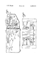
- FIG. 1 is a side elevation of a burster made according to the invention with prior art components shown schematically;
- FIG. 2 is a plan view of a tractor and trimmer assembly utilized in the burster.
- FIG. 1 An exemplary embodiment of a burster made according to the invention is illustrated in FIG. 1 and is seen to be formed of two basic parts.
- the first is a burster section, generally designated 10, which preferably is made according to the teaching of the previously identified Pine patent. The details of said Pine patent are therefore, herein incorporated by reference.
- the second section is generally designated 12 and is a tractor trimmer section disposed on the infeed end of the burster 10.
- the burster section 10 includes stationery guides 14 which guide stationery received from the tractor trimmer section 12 through a first pair of bursting rolls, generally designated 16, known as the infeed rolls.
- the guides 14 further guide the stationery to a pair of outfeed rolls, generally designated 18.
- the guides 14 essentially establish a path of stationery travel through the burster.
- the infeed rolls 16 include an upper roll 20 and a lower roll 22.
- the lower roll 22 is positively driven by a motor 24 via a suitable mechanical connection shown schematically at 26 at a first angular velocity shown at 28.
- the upper roll 20 is in substantial abutment with the lower roll 22 and is driven thereby as a result of contact between the peripheral surfaces of the rolls.
- the upper roll 20 is, in effect, an idler roll.
- the same includes a relief 30 in its periphery for the purposes mentioned by Pine.
- the outfeed rolls 18 include an upper, idler roll 32 and a lower, positively driven roll 34.
- the roll 34 is driven by the motor 24 via a mechanical connection shown schematically at 36, generally at an angular velocity considerably greater than that of the infeed driven roll 22. Frequently, where the rolls are of the same diameter, the outfeed driven roll 34 would be driven at twice the angular velocity of the driven infeed roll 22 as shown by the designation at 38.
- the precise ratios utilized will be dependent upon roll diameter, the essential characteristic being that the peripheral speed of the outfeed driven roller 34 be considerably greater than the peripheral speed of the infeed driven roller 22.
- the upper outfeed roller 32 is driven by frictional contact with the driven outfeed roller 34.
- the manner in which continuous business form stationery is separated into individual form lengths along transverse lines of weakening by the burster section 10 is well known and need not be explained herein.
- the tractor-trimmer section 12 includes a support surface 50 for stationery entering the apparatus.
- the support surface 50 defines a forward continuation of the path of stationery travel as also defined by the guides 14.
- a rotatable shaft 52 extends across the infeed end of the apparatus just below the surface 50.
- a guide shaft 54 is similarly disposed in space relation to the shaft 52.
- the shafts 52 and 54 mount conventional pinfeed tractor assemblies 56.
- the tractors 56 slide along the shafts 52 and 54 toward and away from the support surface 50 so as to accommodate the apparatus for a variety of stationery widths.
- Each tractor assembly includes a conventional, molded plastic belt 58 which in turn includes upstanding pins or projections 60, usually on half-inch centers, which are received in punched holes in the margins of the stationery to be processed.
- the belt 58 is trained about a drive sprocket (not shown) mounted on the shaft 52 and keyed thereto as well as an idler sprocket or sheave journalled on the shaft 54. Consequently, when the shaft 52 is driven by means to be described hereinafter, and the stationery has its control punch margins engaged with the pins 60 on one or both of the tractors 56, such stationery will be advanced along the path of travel, ultimately to the burster section 10.
- upper and lower shafts 70 and 72 are spaced about support surface 50 at a location intermediate the burster section 10 and the tractor devices 56. Both the shafts 70 and 72 are journalled for rotation and slidably mount a pair of trimmer assemblies 74 which may be of conventional construction and employed to trim stationery advanced along the path of its travel prior to its being burst. For example, the trimmers 74 may be utilized to trim the control punch margins from the stationery.
- the tractor-trimmer section 12 journals a shaft 80 which has a first sheave 82 mounted thereon.
- a belt 84 which may be a timing belt, is trained about the sheave 82 and about a similar sheave 86 mounted on the output shaft of the motor 24. Consequently, when the motor 24 is energized, the sheave 82 and the shaft 80 will be rotatably driven.
- a sheave 88 is mounted on the shaft 80 for rotation therewith and a belt 90, which may be a timing belt, extends thereabout and is also trained about a sheave 92 mounted on the shaft 72 and the input side of a one-way clutch 94 of conventional construction mounted on the shaft 52.
- Idler gears 96 and 98 are engaged respectively with gears 100 and 102 on the shaft 72 and 70 whereby rotation of the shaft 72 by the belt 90 is likewise conveyed to the shaft 70 to provide a drive for the trimmer assemblies 74.
- the one-way clutch 94 for the configuration of the components shown in FIG. 1, is such that if the belt 90 were held stationary, the shaft 52 could be advanced in the counterclockwise direction but could not be moved in the clockwise direction.
- Drive speed of the tractors 56 with respect to the peripheral speed of the driven infeed roller 22 is critical to achieve uniformly acceptable bursting over substantially all conventional form lengths of stationery formed of varying paper weights. It has been determined that the rate of drive that would be provided to stationery solely by the tractor 56 must be in the range from just less than to 10% less than the drive rate that would be provided to the stationery if positively driven by the driven infeed roller 22. If this speed range is deviated from, unacceptable bursting may occur for differing form lengths and differing paper weights. For example, if the tractor is driven at a rate less than the aforementioned range, bursting difficulties will occur in forms made of light paper weights such as paper of a 12 lb. weight or less.
- the unique burster of the present invention eliminates paper handling problems such as skewing associated with low cost bursters employing untimed, idler rolls in the bursting section.
- the specified drive ratio for paper by the tractor versus the infeed drive roller provides good bursting for virtually all conventional form lengths utilized today without respect to the weight of paper of which the stationery is formed.
- the system automatically accommodates wear inherent in idler roller systems in that over-feeding cannot occur even after extended use, and thus wear, of the burster.
- provision of tractors provides a supplemental benefit in allowing the use of trimmers in low cost, untimed bursters for the first time.
Abstract
Description
______________________________________
Tractor
Paper Speed
As A
Percentage of
The Driven
Infeed
Roller Speed
         RAN WELL   RAN POORLY  DID NOT RUN
______________________________________
62%      31/2" (Heavy)
                    31/2" (Light)
                                11" (Light)
                    51/2" (Heavy)
                    81/2" (Heavy)
                    11" (Heavy)
80%      31/2" (Heavy &
                    11" (Heavy) 11" (Light)
         Light)
         51/2" &
         81/2" (Heavy)
  98.7%  31/2"-11"  --          --
         (All Weights)
100%     31/2" & 51/2"
                    --          81/2" & 11"
         (All Weights)          (All Weights)
______________________________________
Claims (4)
Priority Applications (1)
| Application Number | Priority Date | Filing Date | Title |
|---|---|---|---|
| US06/091,336 US4269341A (en) | 1979-11-05 | 1979-11-05 | Stationery burster |
Applications Claiming Priority (1)
| Application Number | Priority Date | Filing Date | Title |
|---|---|---|---|
| US06/091,336 US4269341A (en) | 1979-11-05 | 1979-11-05 | Stationery burster |
Publications (1)
| Publication Number | Publication Date |
|---|---|
| US4269341A true US4269341A (en) | 1981-05-26 |
Family
ID=22227244
Family Applications (1)
| Application Number | Title | Priority Date | Filing Date |
|---|---|---|---|
| US06/091,336 Expired - Lifetime US4269341A (en) | 1979-11-05 | 1979-11-05 | Stationery burster |
Country Status (1)
| Country | Link |
|---|---|
| US (1) | US4269341A (en) |
Cited By (9)
| Publication number | Priority date | Publication date | Assignee | Title |
|---|---|---|---|---|
| US4401249A (en) * | 1981-12-29 | 1983-08-30 | Burroughs Corporation | Automatic burster apparatus having a double bursting bar |
| US4529114A (en) * | 1983-09-09 | 1985-07-16 | Moore Business Forms, Inc. | Form burster |
| US5104022A (en) * | 1988-12-29 | 1992-04-14 | Toppan Moore Co., Ltd. | Continuous paper sheet tearing-up apparatus |
| US5540369A (en) * | 1993-12-07 | 1996-07-30 | Moore Business Forms, Inc. | Detaching linerless labels |
| US5622302A (en) * | 1993-09-21 | 1997-04-22 | Moore Business Forms, Inc. | Apparatus and methods for bursting interstacked longitudinally offset form sets from continuous webs |
| US5735443A (en) * | 1993-09-08 | 1998-04-07 | Moore Business Forms Inc | Single part burster |
| US6293469B1 (en) | 1994-12-20 | 2001-09-25 | Dh Technology Inc. | Transaction printer |
| US20040003695A1 (en) * | 2002-04-17 | 2004-01-08 | Norman Diamond | Paper cutting and apparatus and method |
| US6712253B2 (en) | 2001-06-04 | 2004-03-30 | American Games, Inc. | Apparatus and method for dispensing tickets |
Citations (9)
| Publication number | Priority date | Publication date | Assignee | Title |
|---|---|---|---|---|
| US2328582A (en) * | 1940-10-16 | 1943-09-07 | Standard Register Co | Strip severing and bursting machine |
| US3161335A (en) * | 1962-07-19 | 1964-12-15 | Uarco Inc | Burster |
| US3484031A (en) * | 1967-07-20 | 1969-12-16 | Uarco Inc | Stationery burster |
| US3493156A (en) * | 1967-06-12 | 1970-02-03 | Uarco Inc | Adjustable outfeed assembly for stationery burster |
| US3514094A (en) * | 1967-06-13 | 1970-05-26 | Uarco Inc | Web deleaver with overriding drive means |
| US3847318A (en) * | 1971-01-04 | 1974-11-12 | Standard Register Co | Burster apparatus |
| US3856196A (en) * | 1973-01-26 | 1974-12-24 | Moore Business Forms Inc | Capstan detacher |
| US3888399A (en) * | 1972-10-31 | 1975-06-10 | Pitney Bowes Inc | Bursting apparatus |
| US3944206A (en) * | 1974-09-30 | 1976-03-16 | Uarco Incorporated | Deleaver for continuous business forms |
-
1979
- 1979-11-05 US US06/091,336 patent/US4269341A/en not_active Expired - Lifetime
Patent Citations (9)
| Publication number | Priority date | Publication date | Assignee | Title |
|---|---|---|---|---|
| US2328582A (en) * | 1940-10-16 | 1943-09-07 | Standard Register Co | Strip severing and bursting machine |
| US3161335A (en) * | 1962-07-19 | 1964-12-15 | Uarco Inc | Burster |
| US3493156A (en) * | 1967-06-12 | 1970-02-03 | Uarco Inc | Adjustable outfeed assembly for stationery burster |
| US3514094A (en) * | 1967-06-13 | 1970-05-26 | Uarco Inc | Web deleaver with overriding drive means |
| US3484031A (en) * | 1967-07-20 | 1969-12-16 | Uarco Inc | Stationery burster |
| US3847318A (en) * | 1971-01-04 | 1974-11-12 | Standard Register Co | Burster apparatus |
| US3888399A (en) * | 1972-10-31 | 1975-06-10 | Pitney Bowes Inc | Bursting apparatus |
| US3856196A (en) * | 1973-01-26 | 1974-12-24 | Moore Business Forms Inc | Capstan detacher |
| US3944206A (en) * | 1974-09-30 | 1976-03-16 | Uarco Incorporated | Deleaver for continuous business forms |
Cited By (10)
| Publication number | Priority date | Publication date | Assignee | Title |
|---|---|---|---|---|
| US4401249A (en) * | 1981-12-29 | 1983-08-30 | Burroughs Corporation | Automatic burster apparatus having a double bursting bar |
| US4529114A (en) * | 1983-09-09 | 1985-07-16 | Moore Business Forms, Inc. | Form burster |
| US5104022A (en) * | 1988-12-29 | 1992-04-14 | Toppan Moore Co., Ltd. | Continuous paper sheet tearing-up apparatus |
| US5735443A (en) * | 1993-09-08 | 1998-04-07 | Moore Business Forms Inc | Single part burster |
| US5622302A (en) * | 1993-09-21 | 1997-04-22 | Moore Business Forms, Inc. | Apparatus and methods for bursting interstacked longitudinally offset form sets from continuous webs |
| US5540369A (en) * | 1993-12-07 | 1996-07-30 | Moore Business Forms, Inc. | Detaching linerless labels |
| US6293469B1 (en) | 1994-12-20 | 2001-09-25 | Dh Technology Inc. | Transaction printer |
| US6439454B1 (en) | 1994-12-20 | 2002-08-27 | Axiohm Transaction Solutions, Inc. | Transaction printer |
| US6712253B2 (en) | 2001-06-04 | 2004-03-30 | American Games, Inc. | Apparatus and method for dispensing tickets |
| US20040003695A1 (en) * | 2002-04-17 | 2004-01-08 | Norman Diamond | Paper cutting and apparatus and method |
Similar Documents
| Publication | Publication Date | Title |
|---|---|---|
| US4261497A (en) | Bursting apparatus | |
| DE3347773C2 (en) | ||
| US4364552A (en) | Method and apparatus for forming a stream of partially overlapping paper sheets or the like | |
| US4269341A (en) | Stationery burster | |
| CH642298A5 (en) | DEVICE FOR SEPARATING PRE-PERFORATED TAPES, PREFERABLY CONTINUOUS BAGS. | |
| US4863154A (en) | Conveyor system for planar objects | |
| DE3337451A1 (en) | SHEET FEEDING SYSTEM | |
| DE2308794B2 (en) | Device for separating and stacking sheets | |
| DE19717183B4 (en) | Method and device for feeding paper to a printer | |
| KR900004516A (en) | Method and device for adjusting the posture of paper | |
| DE3023893C2 (en) | ||
| US3048393A (en) | Sheet separating apparatus | |
| DE60012159T2 (en) | PROCESSING LEAF MATERIAL | |
| IE38881L (en) | Web severing | |
| DE19520342A1 (en) | Device for feeding blanks | |
| EP1268329B1 (en) | Device for cutting paper webs | |
| KR840006954A (en) | Sheet feeding method and apparatus therefor | |
| DE2646949A1 (en) | WRAPPING PAPER FEED DEVICE IN A COIN PACKAGING MACHINE | |
| DE3503168C2 (en) | ||
| US3847318A (en) | Burster apparatus | |
| US4473218A (en) | Feeder tray for continuous forms bursting | |
| DE2951252A1 (en) | TEMPLATE FEEDER | |
| US5595334A (en) | Vacuum and tractor drive for paper web | |
| AU541280B2 (en) | Thin sheet feeding apparatus | |
| US4513959A (en) | Sheet deceleration apparatus |
Legal Events
| Date | Code | Title | Description |
|---|---|---|---|
| STCF | Information on status: patent grant |
Free format text: PATENTED CASE |
|
| AS | Assignment |
Owner name: SUMITOMO BANK, LIMITED, NEW YORK BRANCH, AS COLLAT Free format text: SECURITY INTEREST;ASSIGNOR:UARCO INCORPORATED;REEL/FRAME:006934/0885 Effective date: 19940309 |
|
| AS | Assignment |
Owner name: UARCO INCORPORATED, ILLINOIS Free format text: RELEASE OF ASSIGNMENT FOR SECURITY;ASSIGNOR:SUMITOMO BANK, LIMITED, NEW YORK BRANCH, AS COLLATERAL AGENT, THE;REEL/FRAME:008975/0559 Effective date: 19971231 |
|
| AS | Assignment |
Owner name: STANDARD REGISTER COMPANY, THE, OHIO Free format text: MERGER;ASSIGNOR:UARCO INCORPORATED;REEL/FRAME:009525/0846 Effective date: 19980324 |
|
| AS | Assignment |
Owner name: BANK OF AMERICA, N.A.,GEORGIA Free format text: NOTICE OF GRANT OF SECURITY INTEREST IN PATENTS;ASSIGNOR:THE STANDARD REGISTER COMPANY;REEL/FRAME:024170/0252 Effective date: 20100331 Owner name: BANK OF AMERICA, N.A., GEORGIA Free format text: NOTICE OF GRANT OF SECURITY INTEREST IN PATENTS;ASSIGNOR:THE STANDARD REGISTER COMPANY;REEL/FRAME:024170/0252 Effective date: 20100331 |
|
| AS | Assignment |
Owner name: THE STANDARD REGISTER COMPANY, OHIO Free format text: SECURITY INTEREST;ASSIGNOR:BANK OF AMERICA, N.A., AS ADMINISTRATIVE AGENT;REEL/FRAME:036283/0153 Effective date: 20150731 Owner name: THE STANDARD REGISTER COMPANY, OHIO Free format text: RELEASE BY SECURED PARTY;ASSIGNOR:BANK OF AMERICA, N.A.;REEL/FRAME:036283/0027 Effective date: 20150731 |
|
| AS | Assignment |
Owner name: THE STANDARD REGISTER COMPANY, OHIO Free format text: RELEASE BY SECURED PARTY;ASSIGNOR:BANK OF AMERICA, N.A., AS ADMINISTRATIVE AGENT;REEL/FRAME:036304/0175 Effective date: 20150731 |