US4045104A - Cabinet structure and method of construction - Google Patents
Cabinet structure and method of construction Download PDFInfo
- Publication number
- US4045104A US4045104A US05/606,099 US60609975A US4045104A US 4045104 A US4045104 A US 4045104A US 60609975 A US60609975 A US 60609975A US 4045104 A US4045104 A US 4045104A
- Authority
- US
- United States
- Prior art keywords
- frame members
- members
- corner
- frame
- sockets
- Prior art date
- Legal status (The legal status is an assumption and is not a legal conclusion. Google has not performed a legal analysis and makes no representation as to the accuracy of the status listed.)
- Expired - Lifetime
Links
Images

Classifications
-
- A—HUMAN NECESSITIES
- A47—FURNITURE; DOMESTIC ARTICLES OR APPLIANCES; COFFEE MILLS; SPICE MILLS; SUCTION CLEANERS IN GENERAL
- A47B—TABLES; DESKS; OFFICE FURNITURE; CABINETS; DRAWERS; GENERAL DETAILS OF FURNITURE
- A47B47/00—Cabinets, racks or shelf units, characterised by features related to dismountability or building-up from elements
- A47B47/02—Cabinets, racks or shelf units, characterised by features related to dismountability or building-up from elements made of metal only
- A47B47/03—Cabinets, racks or shelf units, characterised by features related to dismountability or building-up from elements made of metal only with panels separate from the frame
Definitions
- This invention relates to a cabinet structure and method of construction wherein the component parts of the structure are held together in a substantially rigid, stressed attitude.
- a cabinet structure which includes a plurality of elongate frame members, and ends of which are hollowed out to define sockets. Holes are located in the side walls of certain ones of the sockets. Also included is a plurality of corner members for joining the ends of the frame members together in a stressed, substantially rigid fashion.
- Each corner member includes a central post adapted to slide longitudinally into the sockets of the frame members, and a pair of legs extending from one end of the central post generally at right angles thereto and at a fixed angle with respect to each other.
- Each leg includes a nipple protruding from one side thereof with the other side of the leg being tapered so that the end of the leg is narrower than the base thereof.
- the legs of the corner members may be pivoted into the sockets of the frame members so that the nipples of the legs are received into corresponding holes in the side walls of the sockets.
- each corner member When the frame members and corner members are assembled into a cabinet structure, the legs of each corner member extends generally horizontally into the sockets of adjacent ends of a pair of horizontally disposed frame members and the central posts of the corner members are received into the sockets of vertically disposed frame members.
- the nipples on the legs of the corner members coact with corresponding holes in the side walls of the sockets of the frame members to maintain the structure in a stressed, substantially rigid configuration.
- the frame members include a pair of flanges which extend from one side thereof to form a generally U-shaped channel. Panels are provided for installation among the framed members with certain ones of the edges of the frame members being received in and carried by the channels of the frame members.
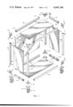
- FIG. 1 is an exploded, perspective view of a cabinet structure made in accordance with the principles of the present invention
- FIGS. 2A, 2B and 2C show an upper corner member and fragmented portions of frame members of the cabinet of FIG. 1 illustrating the manner of joining the corner member and frame members together;
- FIG. 3 shows a bottom corner member, fragmented portions of frame members joined to the corner member, and a detached base member of the cabinet of FIG. 1;
- FIG. 4 is a cross-sectional view of the central post of a corner member and a frame member showing detent apparatus disposed in the central post.
- the cabinet structure of the present invention includes a cabinet frame 2 (FIG. 1) which carries a plurality of panels such as a top panel 4, a bottom panel 6, a back panel 8, and two end panels 10 and 12.
- the frame 2 rests on four base members 14 which may include casters or wheels 16 for moving the cabinet.
- the unique configuration and design of the components of the frame 2 allow for maintaining the frame in a mechanically stressed and rigid disposition and for maintaining the panels and base members in place.
- sliding or hinged doors could also be mounted in the cabinet as could additional internal shelves, partitions, etc.
- the components of the cabinet frame 2 of FIG. 1 include bottom corner members 18, top corner members 20, bottom tubular frame members 22, top tubular frame members 24 and vertical tubular frame members 26.
- the corner members 18 and 20 each includes a body portion 30 (composite FIG. 2), a central post 32 which projects outwardly from the body, and a pair of legs 34 and 36 projecting from the body 30 at substantially a right angle with respect to the central post 32 and with respect to each other.
- the top and bottom corner members are essentially alike, the bodies of the upper corner members 20 are somewhat thicker than the bodies of the bottom corner members 18. This is best seen in composite FIG. 2 and FIG. 3 which respectively show a top corner member and a bottom corner member. Note that the thickness of the body of the top corner member 20 is substantially the same as the thickness of the frame member 24 (composite FIG. 2) whereas the thickness of the body of the bottom corner member 18 is less than the thickness of the frame member 22 (FIG. 3).
- the body 30 of the corner members has the shape of a right angle with flat end faces 30a and 30b formed at right angles to one another and out from which the legs 34 and 36 project (FIG. 1 and composite FIG. 2).
- the central post 32 projects either from the bottom surface of the body 30 (composite FIG. 2) or from the top surface of the body (FIG. 3).
- the central post 32 of each of the corner members 18 and 20 has a substantially square cross section, as does the base portion 40 of each of the legs of the corner members 18 and 20.
- the side of each leg closest to the central post 32 of the corner members 18 and 20 is tapered so that the leg becomes narrower at the end thereof. The purpose of this tapering will be discussed later when describing the method of assembling the cabinet.
- Projecting from the side of each leg opposite the tapered side is a rigid nipple 42.
- the nipples 42 are generally cylindrical in shape and are adapted to be received in holes 44 located near the ends of the frame members.
- Each central post 32 of the corner members includes detent apparatus having a nipple 46 (FIG. 1) which is spring biased to project outwardly from one side of the central post. This structure will be described hereafter more fully in conjunction with FIG. 4.
- the frame members are tubular or hollowed out to define sockets in the ends thereof, and generally square in cross section, as best seen in FIG. 4.
- Projecting from adjacent corners of the frame member are a pair of flanges 50 and 52.
- the flanges extend parallel with one another to form a generally U-shaped channel 54, again as best seen in FIG. 4.
- the frame members include holes 44 located near each end of the members either in the top walls of the members opposite the channel 54 (in the case of the top frame members 24) or in the bottom walls of the frame members which participate in forming the channels 54 (in the case of the bottom frame members 22 and vertical frame members 26). These holes are designed to receive the rigid nipples 42 projecting from the legs of the corner members or the nipples 46 of the detent apparatus disposed in the central posts 32.
- the cross sections of the central posts 32 and of the base portions of the legs 34 and 36 are dimensioned to fit snuggly in the ends of the frame members, with the ends of the frame members abutting against end faces 30a and 30b and the surface of the body 30 from which the central post 32 projects.
- the interior surfaces of the channels 54 of the frame members are dimensioned to receive edges of the end panels 10 and 12.
- Flanges 60 are formed on the inner sides of the top frame members 24 and the bottom frame members 22 to project inwardly from the frame members toward the center of the cabinet frame 2. These flanges 60 provide a support for the top panel 4 and the bottom panel 6 as generally indicated in FIG. 1. Of course, other arrangements could be provided for supporting the top and bottom panels and the use of flanges 60 on the frame members is merely one way of doing this. (It might be noted that the use of such flanges was disclosed in the aforecited patent, U.S. Pat. No. 3,815,966.)
- Base member supports 14 for the cabinet are shown in FIG. 3.
- the base members are formed of a generally flat plate 70 and a pair of upstanding ridges 72 and 74 formed on the plate 70.
- the ridges 72 and 74 extend laterally from a substantially square corner section 76 to form a right angle with respect to one another.
- the ridges 72 and 74 are shaped to be received snuggly within the channels 54 of the frame members.
- the corner section 76 of the base member 14 abuts against the bottom face of the body 30 of the lower corner member 18. In this manner, the ridges 72 and 74 and the corner section 76 of the support member 14 provide support for corresponding lower frame members and corner members.
- a wheel or caster assembly 16 may be mounted to the underneath surface of the base member 14 to enable ready movement of the cabinet.
- Such wheel or caster assembly could be secured to such underneath surface by screws, or suitable adhesive, etc.
- FIG. 4 shows the details of the detent apparatus mounted in the central posts 32 of the corner members.
- This detent apparatus includes a spring 80 positioned in a hollowed out portion 82 of the central post 32.
- the spring 80 pushes against a nipple or ball end base 84 to thereby bias the nipple or ball end 46 outwardly of the central post 32 and into a hole 44 located in the channel 54 of a corresponding frame member.
- the nipple 46 may be forced inwardly by a knife blade, etc., in the well known manner to enable sliding the central post 32 into or out of the end of a frame member.
- the ball end base 84 is shown in engagement with a portion of the wall of central post 32 which surrounds the opening in the wall through which ball end 46 protrudes, it should be understood that such portion of the wall may be eliminated so that the ball end base 84 is held in place in the hollowed out portion 82 only when the central post 32 is inserted in a corresponding frame member. With this arrangement, the detent apparatus may be readily inserted and removed from the central post 32 since there is nothing to hold it in place until the central post is inserted in a frame member.
- Assembly of the cabinet consists of coupling the corner members to the frame members and properly placing the panels among the frame members.
- the corner members are fitted into the ends of the frame members by a type of pivoting action best understood by reference to composite FIG. 2.
- the narrow end of each leg is inserted in the end of a frame member as indicated generally in FIG. 2A until the upper portion of the flat end face 30b abuts against the end edge of the frame member 24 as indicated in FIG. 2B.
- the central post 32 By then pivoting the central post 32 downwardly and toward the frame member 24 as indicated by the arrow in FIG. 2B, the rigid nipple 42 which projects from the leg 36 moves into the hole 44 located in the top of the frame member.
- the corner member 20 is pivoted downwardly until the rest of the end face 30b abuts against the end of the frame member 24 as indicated in FIG. 2C. It should be understood, of course, that either the corner member may be pivoted into coupling engagement in the end of a frame member or alternatively that the frame member may be pivoted about the leg of a corner member.
- the central posts 32 of the corner members may be simply slid longitudinally into the ends of the frame members as generally indicated in FIG. 2C.
- the detent apparatus of the central posts would be held in a depressed attitude while sliding the central post into the end of a frame member until the nipple of the detent apparatus became aligned with a corresponding hole in the frame member at which time the nipple would be biased outwardly into the hole as generally indicated in FIG. 4.
- An exemplary procedure for assembling the entire cabinet is as follows. Two upper corner members 20 are pivoted into the two ends of the other top end frame member and then these two corner members are pivoted simultaneously into place on the ends of the front and back top frame members to thereby form an upper rectangle.
- the bottom frame members 22 and corner members 18 are similarly assembled to form a lower rectangle and then the vertical frame members 26 together with the end panels positioned therebetween are placed onto the central posts of the bottom corner members.
- the upper assembled rectangle is then placed onto the vertical frame members 26 so that the central posts of the upper corner members are inserted into the ends of the vertical frame members and so that the upper edges of the two end panels are received in the channels of corresponding top end frame members.
- the bottom panel 6, back panel 8 and top panel 4 may then be put in place as indicated in FIG. 1.
- the cabinet may be quickly and easily assembled into a rigid, mechanically stressed structure.
Abstract
A cabinet structure and method of construction therefor include provision of a plurality of tubular frame members having holes in the interior side walls thereof near the ends of the members, and a plurality of corner members for joining the frame members together. The corner members have a central post and a pair of legs extending from one end of the central post at substantially a right angle thereto and at substantially a right angle with respect to each other. One side of each leg is tapered to become narrower at its end and each leg has a nipple protruding from the side opposite the tapered side. The corner members are fitted in the frame members by pivoting the legs thereof into the ends of the frame members so that the nipples are received into corresponding holes in the side walls of the frame members. The frame members are generally rectangular in cross-section and includes a pair of flanges which extend in a parallel fashion from a pair of adjacent corners of the frame member. A plurality of panels are provided for fitting among the frame members in which certain of the edges of the panels are received between the flanges of certain of the frame members.
Description
This invention relates to a cabinet structure and method of construction wherein the component parts of the structure are held together in a substantially rigid, stressed attitude.
A variety of cabinet designs have been proposed in recent years, with the object of each design typically being simplicity in construction, ease of assembly, and minimization of the number of component parts. See, for example, U.S. Pat. Nos. 2,806,755, 3,272,582 and 3,815,966.
One drawback with most prior art cabinet designs is that screws or screws and bolts are typically required to maintain the structure in a rigid attitude or alternatively the structure is fabricated with the component parts permanently bonded together. In the former case, assembly of the cabinets is oftentimes difficult and, because screws tend to loosen with movement, the cabinets lose their rigidity with time. In the latter case, there is typically no rigidity problem but storage and shipping is difficult and costly because the cabinet effectively has no disassembled, compact state.
It is an object of the present invention to provide a cabinet structure and method of construction requiring few component parts.
It is also an object of the present invention to provide a cabinet structure having component parts which are substantially alike and therefore interchangeable.
It is a further object of the present invention to provide a cabinet structure requiring no bolts or screws for holding the component parts thereof together.
It is still another object of the present invention to provide a cabinet structure which may be readily assembled and disassembled and which, when assembled, is maintained in a substantially rigid, stressed attitude.
The above and other objects of the present invention are realized in an illustrative embodiment of a cabinet structure which includes a plurality of elongate frame members, and ends of which are hollowed out to define sockets. Holes are located in the side walls of certain ones of the sockets. Also included is a plurality of corner members for joining the ends of the frame members together in a stressed, substantially rigid fashion. Each corner member includes a central post adapted to slide longitudinally into the sockets of the frame members, and a pair of legs extending from one end of the central post generally at right angles thereto and at a fixed angle with respect to each other. Each leg includes a nipple protruding from one side thereof with the other side of the leg being tapered so that the end of the leg is narrower than the base thereof. With this construction, the legs of the corner members may be pivoted into the sockets of the frame members so that the nipples of the legs are received into corresponding holes in the side walls of the sockets.
When the frame members and corner members are assembled into a cabinet structure, the legs of each corner member extends generally horizontally into the sockets of adjacent ends of a pair of horizontally disposed frame members and the central posts of the corner members are received into the sockets of vertically disposed frame members. The nipples on the legs of the corner members coact with corresponding holes in the side walls of the sockets of the frame members to maintain the structure in a stressed, substantially rigid configuration.
In accordance with one aspect of the invention, the frame members include a pair of flanges which extend from one side thereof to form a generally U-shaped channel. Panels are provided for installation among the framed members with certain ones of the edges of the frame members being received in and carried by the channels of the frame members.
The above and other objects, features and advantages of the present invention will become apparent from a consideration of the following detailed description presented in connection with the accompanying drawings in which:
FIG. 1 is an exploded, perspective view of a cabinet structure made in accordance with the principles of the present invention;
FIGS. 2A, 2B and 2C show an upper corner member and fragmented portions of frame members of the cabinet of FIG. 1 illustrating the manner of joining the corner member and frame members together;
FIG. 3 shows a bottom corner member, fragmented portions of frame members joined to the corner member, and a detached base member of the cabinet of FIG. 1; and
FIG. 4 is a cross-sectional view of the central post of a corner member and a frame member showing detent apparatus disposed in the central post.
The cabinet structure of the present invention includes a cabinet frame 2 (FIG. 1) which carries a plurality of panels such as a top panel 4, a bottom panel 6, a back panel 8, and two end panels 10 and 12. The frame 2 rests on four base members 14 which may include casters or wheels 16 for moving the cabinet. The unique configuration and design of the components of the frame 2 allow for maintaining the frame in a mechanically stressed and rigid disposition and for maintaining the panels and base members in place. Of course, sliding or hinged doors could also be mounted in the cabinet as could additional internal shelves, partitions, etc.
The components of the cabinet frame 2 of FIG. 1 include bottom corner members 18, top corner members 20, bottom tubular frame members 22, top tubular frame members 24 and vertical tubular frame members 26. The corner members 18 and 20 each includes a body portion 30 (composite FIG. 2), a central post 32 which projects outwardly from the body, and a pair of legs 34 and 36 projecting from the body 30 at substantially a right angle with respect to the central post 32 and with respect to each other. Although the top and bottom corner members are essentially alike, the bodies of the upper corner members 20 are somewhat thicker than the bodies of the bottom corner members 18. This is best seen in composite FIG. 2 and FIG. 3 which respectively show a top corner member and a bottom corner member. Note that the thickness of the body of the top corner member 20 is substantially the same as the thickness of the frame member 24 (composite FIG. 2) whereas the thickness of the body of the bottom corner member 18 is less than the thickness of the frame member 22 (FIG. 3).
The body 30 of the corner members has the shape of a right angle with flat end faces 30a and 30b formed at right angles to one another and out from which the legs 34 and 36 project (FIG. 1 and composite FIG. 2). The central post 32 projects either from the bottom surface of the body 30 (composite FIG. 2) or from the top surface of the body (FIG. 3).
The central post 32 of each of the corner members 18 and 20 has a substantially square cross section, as does the base portion 40 of each of the legs of the corner members 18 and 20. The side of each leg closest to the central post 32 of the corner members 18 and 20 is tapered so that the leg becomes narrower at the end thereof. The purpose of this tapering will be discussed later when describing the method of assembling the cabinet. Projecting from the side of each leg opposite the tapered side is a rigid nipple 42. The nipples 42 are generally cylindrical in shape and are adapted to be received in holes 44 located near the ends of the frame members. Each central post 32 of the corner members includes detent apparatus having a nipple 46 (FIG. 1) which is spring biased to project outwardly from one side of the central post. This structure will be described hereafter more fully in conjunction with FIG. 4.
The frame members are tubular or hollowed out to define sockets in the ends thereof, and generally square in cross section, as best seen in FIG. 4. Projecting from adjacent corners of the frame member are a pair of flanges 50 and 52. The flanges extend parallel with one another to form a generally U-shaped channel 54, again as best seen in FIG. 4. As earlier mentioned, the frame members include holes 44 located near each end of the members either in the top walls of the members opposite the channel 54 (in the case of the top frame members 24) or in the bottom walls of the frame members which participate in forming the channels 54 (in the case of the bottom frame members 22 and vertical frame members 26). These holes are designed to receive the rigid nipples 42 projecting from the legs of the corner members or the nipples 46 of the detent apparatus disposed in the central posts 32.
The cross sections of the central posts 32 and of the base portions of the legs 34 and 36 are dimensioned to fit snuggly in the ends of the frame members, with the ends of the frame members abutting against end faces 30a and 30b and the surface of the body 30 from which the central post 32 projects. The interior surfaces of the channels 54 of the frame members are dimensioned to receive edges of the end panels 10 and 12.
Flanges 60 are formed on the inner sides of the top frame members 24 and the bottom frame members 22 to project inwardly from the frame members toward the center of the cabinet frame 2. These flanges 60 provide a support for the top panel 4 and the bottom panel 6 as generally indicated in FIG. 1. Of course, other arrangements could be provided for supporting the top and bottom panels and the use of flanges 60 on the frame members is merely one way of doing this. (It might be noted that the use of such flanges was disclosed in the aforecited patent, U.S. Pat. No. 3,815,966.)
Base member supports 14 for the cabinet are shown in FIG. 3. The base members are formed of a generally flat plate 70 and a pair of upstanding ridges 72 and 74 formed on the plate 70. The ridges 72 and 74 extend laterally from a substantially square corner section 76 to form a right angle with respect to one another. The ridges 72 and 74 are shaped to be received snuggly within the channels 54 of the frame members. When the ridges 72 and 74 are inserted in the channels 54, the corner section 76 of the base member 14 abuts against the bottom face of the body 30 of the lower corner member 18. In this manner, the ridges 72 and 74 and the corner section 76 of the support member 14 provide support for corresponding lower frame members and corner members.
Advantageously, a wheel or caster assembly 16 may be mounted to the underneath surface of the base member 14 to enable ready movement of the cabinet. Such wheel or caster assembly could be secured to such underneath surface by screws, or suitable adhesive, etc.
As indicated earlier, FIG. 4 shows the details of the detent apparatus mounted in the central posts 32 of the corner members. This detent apparatus includes a spring 80 positioned in a hollowed out portion 82 of the central post 32. The spring 80 pushes against a nipple or ball end base 84 to thereby bias the nipple or ball end 46 outwardly of the central post 32 and into a hole 44 located in the channel 54 of a corresponding frame member. The nipple 46 may be forced inwardly by a knife blade, etc., in the well known manner to enable sliding the central post 32 into or out of the end of a frame member. Although the ball end base 84 is shown in engagement with a portion of the wall of central post 32 which surrounds the opening in the wall through which ball end 46 protrudes, it should be understood that such portion of the wall may be eliminated so that the ball end base 84 is held in place in the hollowed out portion 82 only when the central post 32 is inserted in a corresponding frame member. With this arrangement, the detent apparatus may be readily inserted and removed from the central post 32 since there is nothing to hold it in place until the central post is inserted in a frame member.
Assembly of the cabinet consists of coupling the corner members to the frame members and properly placing the panels among the frame members. The corner members are fitted into the ends of the frame members by a type of pivoting action best understood by reference to composite FIG. 2. Specifically, the narrow end of each leg is inserted in the end of a frame member as indicated generally in FIG. 2A until the upper portion of the flat end face 30b abuts against the end edge of the frame member 24 as indicated in FIG. 2B. By then pivoting the central post 32 downwardly and toward the frame member 24 as indicated by the arrow in FIG. 2B, the rigid nipple 42 which projects from the leg 36 moves into the hole 44 located in the top of the frame member. The corner member 20 is pivoted downwardly until the rest of the end face 30b abuts against the end of the frame member 24 as indicated in FIG. 2C. It should be understood, of course, that either the corner member may be pivoted into coupling engagement in the end of a frame member or alternatively that the frame member may be pivoted about the leg of a corner member.
The central posts 32 of the corner members may be simply slid longitudinally into the ends of the frame members as generally indicated in FIG. 2C. Of course, the detent apparatus of the central posts would be held in a depressed attitude while sliding the central post into the end of a frame member until the nipple of the detent apparatus became aligned with a corresponding hole in the frame member at which time the nipple would be biased outwardly into the hole as generally indicated in FIG. 4.
When the legs of a corner member are in place in the ends of corresponding frame members, and the central post 32 is held in a generally vertical attitude by a vertical frame member 26, the legs of the corner member cannot be withdrawn from the ends of the frame members because the nipples 42 are held in the holes 44. The cabinet is thus held in a mechanically stressed, substantially rigid configuration by reason of the structure of the corner members and frame members.
An exemplary procedure for assembling the entire cabinet is as follows. Two upper corner members 20 are pivoted into the two ends of the other top end frame member and then these two corner members are pivoted simultaneously into place on the ends of the front and back top frame members to thereby form an upper rectangle. The bottom frame members 22 and corner members 18 are similarly assembled to form a lower rectangle and then the vertical frame members 26 together with the end panels positioned therebetween are placed onto the central posts of the bottom corner members. The upper assembled rectangle is then placed onto the vertical frame members 26 so that the central posts of the upper corner members are inserted into the ends of the vertical frame members and so that the upper edges of the two end panels are received in the channels of corresponding top end frame members. The bottom panel 6, back panel 8 and top panel 4 may then be put in place as indicated in FIG. 1. It may be desirable to hold the back panel in position by some type of clip or adhesive or other fastening means. Finally, the base members 14 are inserted into position in the channels of the lower frame members 22 as generally indicated in FIG. 3. In the manner described, the cabinet may be quickly and easily assembled into a rigid, mechanically stressed structure.
It is to be understood that the above-described arrangement is only illustrative of the application of the principles of the present invention. Numerous other modifications and alternative arrangements may be devised by those skilled in the art without departing from the spirit and scope of the present invention and the appended claims are intended to cover such modifications and arrangements.
Claims (6)
1. A cabinet structure comprising
a plurality of elongate frame members, the ends of which are hollowed out to define sockets, and at least certain ones of which include a hole in a side wall of each socket, and
a plurality of corner members for joining the ends of the frame members to form a cabinet structure, each of said corner members including
a central post adapted to slide longitudinally into the sockets of the frame members, and
a pair of legs extending substantially perpendicularly from one end of the central post at a predetermined angle with respect to each other, each leg having a rigid nipple protruding from one side of the leg opposite the side closest to the central post, with the other side of each leg being tapered such that the end of the leg is narrower than the base thereof to thereby enable slipping the leg into the sockets of the frame members so that the nipple of the leg is received into a hole of the sidewall of the sockets,
four of said frame members being arranged to form a lower rectangle,
four of said corner members being disposed at the corners of the rectangle, with the legs of each such corner members extending into corresponding contiguous sockets of the frame members and the central posts of such corner members extending upwardly,
four other of said frame members being arranged to form an upper rectangle,
four other of said corner members being disposed at the corners of the upper rectangle, with the legs of each such corner members extending into corresponding contiguous sockets of the upper frame members and the central posts of such corner members extending downwardly, and
four of said frame members being arranged to extend generally vertically between corresponding corners of the lower and upper rectangles, with the central posts of corresponding corner members extending into the sockets of the verticle frame members to thereby provide a unified cabinet frame.
2. A cabinet structure as in claim 1 wherein the outside cross-sectional dimensions of said central posts and the bases of said legs are substantially the same as the inside cross-sectional dimensions of the sockets of said frame members.
3. A cabinet structure as in claim 2 wherein each of said frame members includes a pair of flanges which extend from one side of the frame member to form a generally U-shaped channel, said cabinet structure further comprising a plurality of panels for placement among the frame members so that at least a portion of the edges of the panels are received within channels of the frame members.
4. A cabinet structure as in claim 3 further comprising a plurality of base members, each including
a base plate, and
a pair of upstanding ridges formed on said base plate and adapted to fit snugly within the channels of said frame members.
5. A cabinet structure as in claim 3 wherein the channels of the frame members forming the lower rectangle face downwardly, wherein the channels of the frame members forming the upper triangle face downwardly, wherein the channels of a first pair of vertical frame members face each other and the channels of a second pair of vertical frame members face each other, wherein first and second panels are disposed within the first and second pair of vertical frame members respectively, the edges of the first and second panels being received into the channels of the vertical frame members and into the channels of corresponding ones of the frame members forming the upper rectangle, wherein the frame members of the upper and lower rectangle include flange means which project inwardly to define supports, and wherein third and fourth panels are disposed to rest on the flange means of the frame members of the upper and lower rectangles respectively.
6. A cabinet structure as in claim 1 wherein each of said corner members includes a detent means disposed in the central post of the corner member, said detent means having a ball end spring biased to project from the side of the center post, and wherein certain other of said frame members include a hole in a side wall of the sockets for receiving the ball end.
Priority Applications (1)
| Application Number | Priority Date | Filing Date | Title |
|---|---|---|---|
| US05/606,099 US4045104A (en) | 1975-08-20 | 1975-08-20 | Cabinet structure and method of construction |
Applications Claiming Priority (1)
| Application Number | Priority Date | Filing Date | Title |
|---|---|---|---|
| US05/606,099 US4045104A (en) | 1975-08-20 | 1975-08-20 | Cabinet structure and method of construction |
Publications (1)
| Publication Number | Publication Date |
|---|---|
| US4045104A true US4045104A (en) | 1977-08-30 |
Family
ID=24426530
Family Applications (1)
| Application Number | Title | Priority Date | Filing Date |
|---|---|---|---|
| US05/606,099 Expired - Lifetime US4045104A (en) | 1975-08-20 | 1975-08-20 | Cabinet structure and method of construction |
Country Status (1)
| Country | Link |
|---|---|
| US (1) | US4045104A (en) |
Cited By (97)
| Publication number | Priority date | Publication date | Assignee | Title |
|---|---|---|---|---|
| US4191029A (en) * | 1977-06-21 | 1980-03-04 | Dunne William A | Water chillers and air cooled refrigeration units |
| US4192562A (en) * | 1978-08-22 | 1980-03-11 | Bishoff Mark L | Interfitting and removable modular, frame, storage units |
| FR2468066A1 (en) * | 1979-10-25 | 1981-04-30 | Vittel Eaux Min | SYSTEM FOR MOUNTING SAME FURNITURE OR OTHER OBJECTS AND PANELS, FURNITURE AND VARIOUS OBJECTS MADE WITH THIS SYSTEM |
| US4348068A (en) * | 1979-01-26 | 1982-09-07 | Fisher & Paykel Limited | Refrigerator casing |
| US4378137A (en) * | 1981-04-09 | 1983-03-29 | The Singer Company | Modular furniture construction |
| FR2533123A1 (en) * | 1982-09-20 | 1984-03-23 | Frydman Georges | DEVICE FORMING STRUCTURE, IN PARTICULAR FOR STORAGE CABINET, FOR EXAMPLE SHELVING |
| US4447096A (en) * | 1982-02-16 | 1984-05-08 | Herder, N.V. | Cabinet assembly system |
| US4562927A (en) * | 1983-05-06 | 1986-01-07 | Cornelius Cannon Inc. | Display rack |
| US4643319A (en) * | 1983-12-09 | 1987-02-17 | Rittal-Werk Rudolf Loh Gmbh & Co. Kg | Framework for a switchboard cabinet |
| US4683634A (en) * | 1985-10-18 | 1987-08-04 | Cole Richard D | Method of making an insulated window space assembly |
| US4786122A (en) * | 1986-10-30 | 1988-11-22 | Luxor Corporation | Cabinet construction |
| US4848610A (en) * | 1987-09-11 | 1989-07-18 | Ching Ming Lai | Structure of shelf at balcony |
| US4854654A (en) * | 1985-10-03 | 1989-08-08 | Proxy Oy | Collapsible cabinet |
| US4859008A (en) * | 1986-10-08 | 1989-08-22 | Eyre Clarence W | Knock-down wardrobe cabinet |
| US4869380A (en) * | 1986-09-26 | 1989-09-26 | Vormet Quality Fabrication Close/Corporation | Frame work |
| US4886326A (en) * | 1988-01-29 | 1989-12-12 | Tetrad Marketing/Sales Ltd. | Interlock system for ready to assemble furniture, and furniture incorporating such system |
| US4962805A (en) * | 1987-12-11 | 1990-10-16 | Lunstead, Inc. | Furniture connector |
| US4997240A (en) * | 1989-03-28 | 1991-03-05 | Siemens Aktiengesellschaft | Modular housing system for electronic equipment |
| US5011240A (en) * | 1989-11-28 | 1991-04-30 | Milcare, Inc. | Segmented side wall cart |
| US5160829A (en) * | 1991-03-25 | 1992-11-03 | Chang Kwei T | Electric heat-convection stove with transparent housing |
| US5240317A (en) * | 1992-01-07 | 1993-08-31 | Presnick Michael C | Knock-down skeletal cabinet |
| US5369549A (en) * | 1992-12-16 | 1994-11-29 | Hewlett-Packard Company | Casing for a device |
| US5407262A (en) * | 1993-08-13 | 1995-04-18 | Sunsor, Inc. | Reinforced modular office file and furniture system |
| US5545845A (en) * | 1994-11-21 | 1996-08-13 | Dsc Communications Corporation | Transportable weathertight EMI shielded cabinet structure |
| US5548085A (en) * | 1994-11-21 | 1996-08-20 | Dsc Communications Corporation | Transportable weathertight and EMI shielded cabinet enclosure |
| US5555987A (en) * | 1993-06-30 | 1996-09-17 | Yoshimura; Sabro | Site-assembled folding shelf |
| US5580137A (en) * | 1995-03-20 | 1996-12-03 | Snap-On Technologies, Inc. | Tool box and one-piece bottom panel therefor |
| US5590939A (en) * | 1994-11-07 | 1997-01-07 | Asc Incorporated | Reconfigurable space frame cabinet |
| US5695081A (en) * | 1994-12-06 | 1997-12-09 | Julius Engineering Ltd. | Uniform shelving system |
| US5820289A (en) * | 1995-08-09 | 1998-10-13 | Schroff Gmbh | Corner joint element |
| US5890607A (en) * | 1997-10-06 | 1999-04-06 | Maglione; Stephen Thomas | Modular display |
| US5997117A (en) * | 1997-06-06 | 1999-12-07 | Chatsworth Products, Inc. | Rack frame cabinet |
| WO2000021410A1 (en) * | 1998-09-25 | 2000-04-20 | Iacobucci S.P.A. | Trolley, in particular for airline applications |
| ES2144371A1 (en) * | 1997-05-21 | 2000-06-01 | Ge Power Controls Belgium B V | Assembly structure of cabinet, particularly suitable for electrical equipment. (Machine-translation by Google Translate, not legally binding) |
| US6202867B1 (en) | 1999-01-04 | 2001-03-20 | Terry Store - Age S.P.A. | Modular structure with modular component parts for making shelves and closets |
| US6223917B1 (en) * | 1998-10-16 | 2001-05-01 | Octanorm-Vertriebs-Gmbh Fuer Bauelemente | Profile arrangement for building exhibition or shop systems |
| US6237783B1 (en) * | 1998-03-27 | 2001-05-29 | Advantest Corporation | Apparatus for storing customer trays |
| KR100365084B1 (en) * | 2000-11-15 | 2002-12-26 | 홈앤텍 주식회사 | prefab system furniture |
| US6634512B2 (en) * | 2000-05-04 | 2003-10-21 | Knuerr-Mechanik Fuer Die Elektronik Aktiengesellschaft | Basic rack |
| US20040004418A1 (en) * | 2002-05-23 | 2004-01-08 | Brendan Wyatt | Indoor-outdoor equipment enclosure and method for assembling the same |
| US20040016713A1 (en) * | 2002-04-01 | 2004-01-29 | Brendan Wyatt | Corner post and manufacturing process for making same |
| US6701570B2 (en) * | 1997-09-09 | 2004-03-09 | Kimball International, Inc. | Standardized furniture unit and bracket therefor |
| US6712436B2 (en) * | 2002-02-08 | 2004-03-30 | Chi-Chuan Chen | Combinational drawer |
| US6796623B1 (en) * | 1999-12-21 | 2004-09-28 | Abb Service S.R.L. | Element for the frame of a cabinet |
| US6902068B1 (en) * | 1999-12-21 | 2005-06-07 | Abb Services S.R.L. | Supporting frame for a cabinet of an electrical panel |
| US20060181184A1 (en) * | 2005-02-16 | 2006-08-17 | G-P Gypsum Corp. | Fire resistant file cabinets and safes, and method of manufacture thereof |
| US7159725B1 (en) * | 2004-01-23 | 2007-01-09 | Gates James P | Balloon holding assembly |
| US20070013279A1 (en) * | 2004-03-23 | 2007-01-18 | Macmillan Michael | Bathroom cabinet and method of installation |
| US20070132345A1 (en) * | 2005-12-08 | 2007-06-14 | Kadeya Enterprise Co., Ltd. | Furniture assembled and disassembled easily and quickly |
| US20070284418A1 (en) * | 2006-05-19 | 2007-12-13 | Fuji Electric Fa Components & Systems Co., Ltd. | Package structure of inverter apparatus and method of manufacturing the same |
| US20080131197A1 (en) * | 2006-11-28 | 2008-06-05 | Hamlen James Gregory | Corner piece for valance interface in cases and containers |
| US20080164794A1 (en) * | 2007-01-08 | 2008-07-10 | Hong Fu Jin Precision Industry (Shenzhen) Co., Ltd. | Modular server cabinet |
| US20080216815A1 (en) * | 2007-03-05 | 2008-09-11 | Lucas Pai | Pedestal structure of a griller |
| US20080271728A1 (en) * | 2007-05-04 | 2008-11-06 | Lucas Pai | Griller with detachable stove |
| US20090110471A1 (en) * | 2007-10-31 | 2009-04-30 | Montminy Jeffrey E | system of fasteners for attaching panels onto modules that are to be installed on an airplane ground support equipment cart |
| US20090194991A1 (en) * | 2008-02-05 | 2009-08-06 | Cheng-En Yang | Iron pipe furniture assembly structure |
| US20090226652A1 (en) * | 2007-03-17 | 2009-09-10 | Peter Jones | Framework for assembly around a gift, surprise or present |
| US20090283488A1 (en) * | 2008-05-19 | 2009-11-19 | Chatsworth Products, Inc. | Seismically hardened two-post electronic equipment rack |
| US20100013363A1 (en) * | 2007-02-25 | 2010-01-21 | Chunsong Wang | Collapsible Cabinet with Fabric Drawers |
| US20100038331A1 (en) * | 2007-01-03 | 2010-02-18 | Schoeller Arca Systems Ab | Rack for transport and storage |
| US20100079042A1 (en) * | 2008-09-30 | 2010-04-01 | Pan-Oston Co. | Modular cabinet |
| US20100102690A1 (en) * | 2008-10-29 | 2010-04-29 | Stephen Tewkesbury | Assembling system for storage and workbench |
| US7718891B2 (en) | 2006-03-13 | 2010-05-18 | Panduit Corp. | Network cabinet |
| US20100181881A1 (en) * | 2009-01-21 | 2010-07-22 | Li-Chung Hsu | Systemic cabinet |
| US20110017691A1 (en) * | 2009-07-21 | 2011-01-27 | Wu Chuan-Ching | Environmental protection shelving combination |
| US20110050052A1 (en) * | 2009-09-01 | 2011-03-03 | Emerson Network Power, Energy Systems, North America, Inc. | Telecommunications Enclosures |
| US20120024811A1 (en) * | 2010-07-28 | 2012-02-02 | Hon Hai Precision Industry Co., Ltd. | Rack frame assembly |
| US8147009B1 (en) | 2007-11-30 | 2012-04-03 | Rider H Joe | Cabinet component system |
| US20120079968A1 (en) * | 2010-10-05 | 2012-04-05 | Lifeguard Structures Llc | Personal protective structure |
| US20130106273A1 (en) * | 2011-10-26 | 2013-05-02 | Nathan A. Levy | Method and system for the production of frame structure for printing presses |
| US20130295317A1 (en) * | 2010-06-17 | 2013-11-07 | Chuan-Ching WU | Paper-made composite furniture |
| WO2013191660A2 (en) * | 2012-06-22 | 2013-12-27 | Design Centro Private Limited | Cabinet framework for a furniture cabinet |
| CN104257113A (en) * | 2014-09-29 | 2015-01-07 | 钟昌繁 | Metal assembling cabinet |
| US20150232113A1 (en) * | 2014-02-18 | 2015-08-20 | Alexander Sabo | Equipment trolley |
| US9126613B2 (en) * | 2014-01-09 | 2015-09-08 | Carter Hoffmann, Inc. | Movable cart |
| CN104973307A (en) * | 2014-04-10 | 2015-10-14 | 袁建江 | Airtight heat insulation box |
| US20150335151A1 (en) * | 2013-01-17 | 2015-11-26 | Shreinerei Wolfgang Fünfgeld | Modular system, in particular for furniture, exhibition structures or the like, and item of furniture or exhibition construction |
| US20160348958A1 (en) * | 2015-05-28 | 2016-12-01 | General Electric Company | Joint members for refrigerator appliance casings |
| CN106175187A (en) * | 2016-08-29 | 2016-12-07 | 唐德利 | A kind of decorating cabinet with function of containing articles |
| US9549482B2 (en) | 2014-09-05 | 2017-01-17 | Emerson Network Power, Energy Systems, North America, Inc. | Cabinet frame enclosures, frame members and corresponding methods |
| EP2759455A3 (en) * | 2013-01-23 | 2017-08-23 | Knauf PFT GmbH & Co. KG | Dolly for a machine, in particular for a construction machine |
| US9936809B2 (en) * | 2016-04-29 | 2018-04-10 | Newage Products, Inc. | Cabinet assembly having a releasable support foot |
| US10029718B2 (en) * | 2015-05-15 | 2018-07-24 | Carlisle Foodservice Products, Llc | Modular cart |
| US20180340560A1 (en) * | 2017-05-08 | 2018-11-29 | Steve Bright | Modular Frame Assembly |
| US10260227B2 (en) * | 2015-06-09 | 2019-04-16 | Rock West Composites, Inc. | Tubular framing system and method |
| CN109906193A (en) * | 2016-09-14 | 2019-06-18 | 卡梅尔·保罗·斯托雷斯 | Corner connector and container comprising the connector |
| AT521657A1 (en) * | 2018-08-28 | 2020-03-15 | Bauer Harald | Furniture kit |
| US10750857B1 (en) * | 2019-01-12 | 2020-08-25 | Michael T. Baker | Lightweight non-combustible decorative mantel |
| US11147416B2 (en) * | 2019-10-09 | 2021-10-19 | William Charles Gardner | Free-standing counter framework |
| US20220074440A1 (en) * | 2018-12-28 | 2022-03-10 | Uni-Troll Europe Aps | A coupling system |
| US20220257007A1 (en) * | 2021-02-16 | 2022-08-18 | Newage Products Inc. | Cabinet assembly |
| DE202023101148U1 (en) | 2023-03-10 | 2023-03-28 | Bastian Schewe | Piece of furniture comprising a frame system |
| US11622458B1 (en) | 2020-12-15 | 2023-04-04 | Chatsworth Products, Inc. | Brush port assembly and method for installing same |
| US11678458B1 (en) | 2020-12-15 | 2023-06-13 | Chatsworth Products, Inc. | Slidable mounting hardware for electronic equipment enclosure and method for installing same |
| WO2023215707A1 (en) * | 2022-05-02 | 2023-11-09 | Werner Co. | Utility cart |
| US11818862B1 (en) | 2020-12-15 | 2023-11-14 | Chatsworth Products, Inc. | Frame structure for electronic equipment enclosure |
| US11920392B1 (en) | 2021-02-02 | 2024-03-05 | Chatsworth Products, Inc. | Electrical bonding door hinges |
Citations (11)
| Publication number | Priority date | Publication date | Assignee | Title |
|---|---|---|---|---|
| US2806755A (en) * | 1955-02-21 | 1957-09-17 | Henry P Glass | Cabinet or desk structures employing framework arranged outside of panel members |
| US3087768A (en) * | 1960-05-18 | 1963-04-30 | Amco Eng | Enclosure |
| US3182846A (en) * | 1961-04-11 | 1965-05-11 | Borg Warner | Cabinet structure |
| US3195968A (en) * | 1962-12-06 | 1965-07-20 | Lok Trim Corp | Knock-down furniture |
| CH396345A (en) * | 1962-03-05 | 1965-07-31 | Dexion Ltd | Connection device for the tubular elements of a frame |
| US3255721A (en) * | 1964-01-02 | 1966-06-14 | Diversification Dev Inc | Composite structure utilizing novel assembling joint |
| US3545625A (en) * | 1969-06-20 | 1970-12-08 | Daniel G Macmillan | Modular construction frame |
| US3736035A (en) * | 1971-06-01 | 1973-05-29 | Dca Educational Products Inc | Modular display assembly |
| US3815966A (en) * | 1972-10-04 | 1974-06-11 | Granite Mill & Fixture Co | Portable cabinet |
| US3835354A (en) * | 1972-09-06 | 1974-09-10 | Pena E Torres | Furniture and room partition components |
| US3890022A (en) * | 1974-09-03 | 1975-06-17 | Howard R Moon | Corner fitting |
-
1975
- 1975-08-20 US US05/606,099 patent/US4045104A/en not_active Expired - Lifetime
Patent Citations (11)
| Publication number | Priority date | Publication date | Assignee | Title |
|---|---|---|---|---|
| US2806755A (en) * | 1955-02-21 | 1957-09-17 | Henry P Glass | Cabinet or desk structures employing framework arranged outside of panel members |
| US3087768A (en) * | 1960-05-18 | 1963-04-30 | Amco Eng | Enclosure |
| US3182846A (en) * | 1961-04-11 | 1965-05-11 | Borg Warner | Cabinet structure |
| CH396345A (en) * | 1962-03-05 | 1965-07-31 | Dexion Ltd | Connection device for the tubular elements of a frame |
| US3195968A (en) * | 1962-12-06 | 1965-07-20 | Lok Trim Corp | Knock-down furniture |
| US3255721A (en) * | 1964-01-02 | 1966-06-14 | Diversification Dev Inc | Composite structure utilizing novel assembling joint |
| US3545625A (en) * | 1969-06-20 | 1970-12-08 | Daniel G Macmillan | Modular construction frame |
| US3736035A (en) * | 1971-06-01 | 1973-05-29 | Dca Educational Products Inc | Modular display assembly |
| US3835354A (en) * | 1972-09-06 | 1974-09-10 | Pena E Torres | Furniture and room partition components |
| US3815966A (en) * | 1972-10-04 | 1974-06-11 | Granite Mill & Fixture Co | Portable cabinet |
| US3890022A (en) * | 1974-09-03 | 1975-06-17 | Howard R Moon | Corner fitting |
Cited By (134)
| Publication number | Priority date | Publication date | Assignee | Title |
|---|---|---|---|---|
| US4191029A (en) * | 1977-06-21 | 1980-03-04 | Dunne William A | Water chillers and air cooled refrigeration units |
| US4192562A (en) * | 1978-08-22 | 1980-03-11 | Bishoff Mark L | Interfitting and removable modular, frame, storage units |
| US4348068A (en) * | 1979-01-26 | 1982-09-07 | Fisher & Paykel Limited | Refrigerator casing |
| FR2468066A1 (en) * | 1979-10-25 | 1981-04-30 | Vittel Eaux Min | SYSTEM FOR MOUNTING SAME FURNITURE OR OTHER OBJECTS AND PANELS, FURNITURE AND VARIOUS OBJECTS MADE WITH THIS SYSTEM |
| EP0028193A1 (en) * | 1979-10-25 | 1981-05-06 | Societe Generale Des Eaux Minerales De Vittel | System for self-assembly of furniture or other objects, and panels, furniture and miscellaneous objects realized by this system |
| US4378137A (en) * | 1981-04-09 | 1983-03-29 | The Singer Company | Modular furniture construction |
| US4447096A (en) * | 1982-02-16 | 1984-05-08 | Herder, N.V. | Cabinet assembly system |
| EP0106734A1 (en) * | 1982-09-20 | 1984-04-25 | Georges Frydman | Device constituting a framework for stacking, for example shelving |
| US4691644A (en) * | 1982-09-20 | 1987-09-08 | Georges Frydman | Frame structure especially for a cabinet, e.g. of the shelved type |
| FR2533123A1 (en) * | 1982-09-20 | 1984-03-23 | Frydman Georges | DEVICE FORMING STRUCTURE, IN PARTICULAR FOR STORAGE CABINET, FOR EXAMPLE SHELVING |
| US4562927A (en) * | 1983-05-06 | 1986-01-07 | Cornelius Cannon Inc. | Display rack |
| US4643319A (en) * | 1983-12-09 | 1987-02-17 | Rittal-Werk Rudolf Loh Gmbh & Co. Kg | Framework for a switchboard cabinet |
| US4854654A (en) * | 1985-10-03 | 1989-08-08 | Proxy Oy | Collapsible cabinet |
| US4683634A (en) * | 1985-10-18 | 1987-08-04 | Cole Richard D | Method of making an insulated window space assembly |
| US4869380A (en) * | 1986-09-26 | 1989-09-26 | Vormet Quality Fabrication Close/Corporation | Frame work |
| US4859008A (en) * | 1986-10-08 | 1989-08-22 | Eyre Clarence W | Knock-down wardrobe cabinet |
| US4786122A (en) * | 1986-10-30 | 1988-11-22 | Luxor Corporation | Cabinet construction |
| US4848610A (en) * | 1987-09-11 | 1989-07-18 | Ching Ming Lai | Structure of shelf at balcony |
| US4962805A (en) * | 1987-12-11 | 1990-10-16 | Lunstead, Inc. | Furniture connector |
| US4886326A (en) * | 1988-01-29 | 1989-12-12 | Tetrad Marketing/Sales Ltd. | Interlock system for ready to assemble furniture, and furniture incorporating such system |
| US4997240A (en) * | 1989-03-28 | 1991-03-05 | Siemens Aktiengesellschaft | Modular housing system for electronic equipment |
| US5011240A (en) * | 1989-11-28 | 1991-04-30 | Milcare, Inc. | Segmented side wall cart |
| US5160829A (en) * | 1991-03-25 | 1992-11-03 | Chang Kwei T | Electric heat-convection stove with transparent housing |
| US5240317A (en) * | 1992-01-07 | 1993-08-31 | Presnick Michael C | Knock-down skeletal cabinet |
| US5369549A (en) * | 1992-12-16 | 1994-11-29 | Hewlett-Packard Company | Casing for a device |
| US5555987A (en) * | 1993-06-30 | 1996-09-17 | Yoshimura; Sabro | Site-assembled folding shelf |
| US5407262A (en) * | 1993-08-13 | 1995-04-18 | Sunsor, Inc. | Reinforced modular office file and furniture system |
| US5590939A (en) * | 1994-11-07 | 1997-01-07 | Asc Incorporated | Reconfigurable space frame cabinet |
| US5545845A (en) * | 1994-11-21 | 1996-08-13 | Dsc Communications Corporation | Transportable weathertight EMI shielded cabinet structure |
| US5548085A (en) * | 1994-11-21 | 1996-08-20 | Dsc Communications Corporation | Transportable weathertight and EMI shielded cabinet enclosure |
| US5695081A (en) * | 1994-12-06 | 1997-12-09 | Julius Engineering Ltd. | Uniform shelving system |
| US5580137A (en) * | 1995-03-20 | 1996-12-03 | Snap-On Technologies, Inc. | Tool box and one-piece bottom panel therefor |
| US5820289A (en) * | 1995-08-09 | 1998-10-13 | Schroff Gmbh | Corner joint element |
| ES2144371A1 (en) * | 1997-05-21 | 2000-06-01 | Ge Power Controls Belgium B V | Assembly structure of cabinet, particularly suitable for electrical equipment. (Machine-translation by Google Translate, not legally binding) |
| US5997117A (en) * | 1997-06-06 | 1999-12-07 | Chatsworth Products, Inc. | Rack frame cabinet |
| US6701570B2 (en) * | 1997-09-09 | 2004-03-09 | Kimball International, Inc. | Standardized furniture unit and bracket therefor |
| US5890607A (en) * | 1997-10-06 | 1999-04-06 | Maglione; Stephen Thomas | Modular display |
| US6237783B1 (en) * | 1998-03-27 | 2001-05-29 | Advantest Corporation | Apparatus for storing customer trays |
| WO2000021410A1 (en) * | 1998-09-25 | 2000-04-20 | Iacobucci S.P.A. | Trolley, in particular for airline applications |
| US6223917B1 (en) * | 1998-10-16 | 2001-05-01 | Octanorm-Vertriebs-Gmbh Fuer Bauelemente | Profile arrangement for building exhibition or shop systems |
| US6202867B1 (en) | 1999-01-04 | 2001-03-20 | Terry Store - Age S.P.A. | Modular structure with modular component parts for making shelves and closets |
| US6902068B1 (en) * | 1999-12-21 | 2005-06-07 | Abb Services S.R.L. | Supporting frame for a cabinet of an electrical panel |
| US6796623B1 (en) * | 1999-12-21 | 2004-09-28 | Abb Service S.R.L. | Element for the frame of a cabinet |
| US6634512B2 (en) * | 2000-05-04 | 2003-10-21 | Knuerr-Mechanik Fuer Die Elektronik Aktiengesellschaft | Basic rack |
| KR100365084B1 (en) * | 2000-11-15 | 2002-12-26 | 홈앤텍 주식회사 | prefab system furniture |
| US6712436B2 (en) * | 2002-02-08 | 2004-03-30 | Chi-Chuan Chen | Combinational drawer |
| US20040016713A1 (en) * | 2002-04-01 | 2004-01-29 | Brendan Wyatt | Corner post and manufacturing process for making same |
| US20070056917A1 (en) * | 2002-04-01 | 2007-03-15 | Brendan Wyatt | Corner post and manufacturing process for making same |
| US6974036B2 (en) | 2002-04-01 | 2005-12-13 | Viasystems Group, Inc. | Corner post and manufacturing process for making same |
| US20050284833A1 (en) * | 2002-04-01 | 2005-12-29 | Brendan Wyatt | Corner post and maufacturing process for making same |
| US7316461B2 (en) | 2002-05-23 | 2008-01-08 | Viasystems Group, Inc. | Indoor-outdoor equipment enclosure and method for assembling the same |
| US20060267464A1 (en) * | 2002-05-23 | 2006-11-30 | Brendan Wyatt | Indoor-outdoor equipment enclosure and method for assembling the same |
| US7086707B2 (en) | 2002-05-23 | 2006-08-08 | Viasystems Group, Inc. | Indoor-outdoor equipment enclosure and method for assembling the same |
| US20040004418A1 (en) * | 2002-05-23 | 2004-01-08 | Brendan Wyatt | Indoor-outdoor equipment enclosure and method for assembling the same |
| US7159725B1 (en) * | 2004-01-23 | 2007-01-09 | Gates James P | Balloon holding assembly |
| US20070013279A1 (en) * | 2004-03-23 | 2007-01-18 | Macmillan Michael | Bathroom cabinet and method of installation |
| US20060181184A1 (en) * | 2005-02-16 | 2006-08-17 | G-P Gypsum Corp. | Fire resistant file cabinets and safes, and method of manufacture thereof |
| US20070132345A1 (en) * | 2005-12-08 | 2007-06-14 | Kadeya Enterprise Co., Ltd. | Furniture assembled and disassembled easily and quickly |
| US7718891B2 (en) | 2006-03-13 | 2010-05-18 | Panduit Corp. | Network cabinet |
| US20070284418A1 (en) * | 2006-05-19 | 2007-12-13 | Fuji Electric Fa Components & Systems Co., Ltd. | Package structure of inverter apparatus and method of manufacturing the same |
| US7715198B2 (en) * | 2006-05-19 | 2010-05-11 | Fuji Electric Fa Components & Systems Co., Ltd. | Package structure of inverter apparatus and method of manufacturing the same |
| US20080131197A1 (en) * | 2006-11-28 | 2008-06-05 | Hamlen James Gregory | Corner piece for valance interface in cases and containers |
| US8002490B2 (en) | 2006-11-28 | 2011-08-23 | Impact Cases Inc. | Corner piece for valance interface in cases and containers |
| US7934608B2 (en) * | 2007-01-03 | 2011-05-03 | Schoeller Arca Systems Ab | Rack for transport and storage |
| US20100038331A1 (en) * | 2007-01-03 | 2010-02-18 | Schoeller Arca Systems Ab | Rack for transport and storage |
| US20080164794A1 (en) * | 2007-01-08 | 2008-07-10 | Hong Fu Jin Precision Industry (Shenzhen) Co., Ltd. | Modular server cabinet |
| US20100013363A1 (en) * | 2007-02-25 | 2010-01-21 | Chunsong Wang | Collapsible Cabinet with Fabric Drawers |
| US20080216815A1 (en) * | 2007-03-05 | 2008-09-11 | Lucas Pai | Pedestal structure of a griller |
| US20090226652A1 (en) * | 2007-03-17 | 2009-09-10 | Peter Jones | Framework for assembly around a gift, surprise or present |
| US20080271728A1 (en) * | 2007-05-04 | 2008-11-06 | Lucas Pai | Griller with detachable stove |
| US20090110471A1 (en) * | 2007-10-31 | 2009-04-30 | Montminy Jeffrey E | system of fasteners for attaching panels onto modules that are to be installed on an airplane ground support equipment cart |
| US8147009B1 (en) | 2007-11-30 | 2012-04-03 | Rider H Joe | Cabinet component system |
| US20090194991A1 (en) * | 2008-02-05 | 2009-08-06 | Cheng-En Yang | Iron pipe furniture assembly structure |
| US7850021B2 (en) * | 2008-02-05 | 2010-12-14 | Cheng-En Yang | Iron pipe furniture assembly structure |
| US20090283488A1 (en) * | 2008-05-19 | 2009-11-19 | Chatsworth Products, Inc. | Seismically hardened two-post electronic equipment rack |
| US8424691B2 (en) | 2008-05-19 | 2013-04-23 | Chatsworth Products, Inc. | Seismically hardened two-post electronic equipment rack |
| US20100079042A1 (en) * | 2008-09-30 | 2010-04-01 | Pan-Oston Co. | Modular cabinet |
| US20100102690A1 (en) * | 2008-10-29 | 2010-04-29 | Stephen Tewkesbury | Assembling system for storage and workbench |
| US7967401B2 (en) * | 2009-01-21 | 2011-06-28 | Li-Chung Hsu | Systemic cabinet |
| US20100181881A1 (en) * | 2009-01-21 | 2010-07-22 | Li-Chung Hsu | Systemic cabinet |
| US20110017691A1 (en) * | 2009-07-21 | 2011-01-27 | Wu Chuan-Ching | Environmental protection shelving combination |
| US8403431B2 (en) * | 2009-09-01 | 2013-03-26 | Emerson Network Power, Energy Systems, North America, Inc. | Telecommunications enclosures |
| US20110050052A1 (en) * | 2009-09-01 | 2011-03-03 | Emerson Network Power, Energy Systems, North America, Inc. | Telecommunications Enclosures |
| US20130295317A1 (en) * | 2010-06-17 | 2013-11-07 | Chuan-Ching WU | Paper-made composite furniture |
| US8292093B2 (en) * | 2010-07-28 | 2012-10-23 | Hon Hai Precision Industry Co., Ltd. | Rack frame assembly |
| US20120024811A1 (en) * | 2010-07-28 | 2012-02-02 | Hon Hai Precision Industry Co., Ltd. | Rack frame assembly |
| US20120079968A1 (en) * | 2010-10-05 | 2012-04-05 | Lifeguard Structures Llc | Personal protective structure |
| US9121188B2 (en) * | 2010-10-05 | 2015-09-01 | Lifeguard Structures Llc | Personal protective structure |
| US20130106273A1 (en) * | 2011-10-26 | 2013-05-02 | Nathan A. Levy | Method and system for the production of frame structure for printing presses |
| US9174429B2 (en) * | 2011-10-26 | 2015-11-03 | Hewlett-Packard Development Company, L.P. | Method and system for the production of frame structure for printing presses |
| WO2013191660A2 (en) * | 2012-06-22 | 2013-12-27 | Design Centro Private Limited | Cabinet framework for a furniture cabinet |
| WO2013191660A3 (en) * | 2012-06-22 | 2014-02-20 | Design Centro Private Limited | Cabinet framework for a furniture cabinet |
| US20150335151A1 (en) * | 2013-01-17 | 2015-11-26 | Shreinerei Wolfgang Fünfgeld | Modular system, in particular for furniture, exhibition structures or the like, and item of furniture or exhibition construction |
| US10085553B2 (en) * | 2013-01-17 | 2018-10-02 | Schreinerei Wolfgang Fünfgeld | Modular system, in particular for furniture, exhibition structures or the like, and item of furniture or exhibition construction |
| EP2759455A3 (en) * | 2013-01-23 | 2017-08-23 | Knauf PFT GmbH & Co. KG | Dolly for a machine, in particular for a construction machine |
| US9126613B2 (en) * | 2014-01-09 | 2015-09-08 | Carter Hoffmann, Inc. | Movable cart |
| US20150232113A1 (en) * | 2014-02-18 | 2015-08-20 | Alexander Sabo | Equipment trolley |
| US9522690B2 (en) * | 2014-02-18 | 2016-12-20 | Karl Storz Gmbh & Co. Kg | Equipment trolley |
| CN104973307A (en) * | 2014-04-10 | 2015-10-14 | 袁建江 | Airtight heat insulation box |
| CN104973307B (en) * | 2014-04-10 | 2017-05-03 | 袁建江 | Airtight heat insulation box |
| US9578772B2 (en) | 2014-09-05 | 2017-02-21 | Emerson Network Power, Energy Systems, North America, Inc. | Cabinet frame enclosures, frame members and corresponding methods |
| US9596778B2 (en) | 2014-09-05 | 2017-03-14 | Emerson Network Power, Energy Systems, North America, Inc. | Cabinet frame enclosures, frame members and corresponding methods |
| US9622369B2 (en) | 2014-09-05 | 2017-04-11 | Emerson Network Power, Energy Systems, North America, Inc. | Cabinet frame enclosures, frame members and corresponding methods |
| US9549482B2 (en) | 2014-09-05 | 2017-01-17 | Emerson Network Power, Energy Systems, North America, Inc. | Cabinet frame enclosures, frame members and corresponding methods |
| CN104257113A (en) * | 2014-09-29 | 2015-01-07 | 钟昌繁 | Metal assembling cabinet |
| US10029718B2 (en) * | 2015-05-15 | 2018-07-24 | Carlisle Foodservice Products, Llc | Modular cart |
| US20160348958A1 (en) * | 2015-05-28 | 2016-12-01 | General Electric Company | Joint members for refrigerator appliance casings |
| US9810474B2 (en) * | 2015-05-28 | 2017-11-07 | Haier Us Appliance Solutions, Inc. | Joint members for refrigerator appliance casings |
| US10260227B2 (en) * | 2015-06-09 | 2019-04-16 | Rock West Composites, Inc. | Tubular framing system and method |
| US9936809B2 (en) * | 2016-04-29 | 2018-04-10 | Newage Products, Inc. | Cabinet assembly having a releasable support foot |
| CN106175187A (en) * | 2016-08-29 | 2016-12-07 | 唐德利 | A kind of decorating cabinet with function of containing articles |
| CN109906193A (en) * | 2016-09-14 | 2019-06-18 | 卡梅尔·保罗·斯托雷斯 | Corner connector and container comprising the connector |
| EP3512784A4 (en) * | 2016-09-14 | 2020-04-01 | Storace, Carmel Paul | Corner connector and a container comprising same |
| US10954030B2 (en) | 2016-09-14 | 2021-03-23 | Carmel Paul Storace | Corner connector and a container comprising same |
| US20180340560A1 (en) * | 2017-05-08 | 2018-11-29 | Steve Bright | Modular Frame Assembly |
| US10982699B2 (en) * | 2017-05-08 | 2021-04-20 | Steve Bright | Modular frame assembly |
| AT521657B1 (en) * | 2018-08-28 | 2021-04-15 | Bauer Harald | Furniture kit |
| AT521657A1 (en) * | 2018-08-28 | 2020-03-15 | Bauer Harald | Furniture kit |
| US20220074440A1 (en) * | 2018-12-28 | 2022-03-10 | Uni-Troll Europe Aps | A coupling system |
| US10750857B1 (en) * | 2019-01-12 | 2020-08-25 | Michael T. Baker | Lightweight non-combustible decorative mantel |
| US11147416B2 (en) * | 2019-10-09 | 2021-10-19 | William Charles Gardner | Free-standing counter framework |
| US11622458B1 (en) | 2020-12-15 | 2023-04-04 | Chatsworth Products, Inc. | Brush port assembly and method for installing same |
| US11818861B1 (en) | 2020-12-15 | 2023-11-14 | Chatsworth Products, Inc. | Frame structure for electronic equipment enclosure |
| US11627677B1 (en) | 2020-12-15 | 2023-04-11 | Chatsworth Products, Inc. | Brush port assembly and method for installing same |
| US11903156B1 (en) | 2020-12-15 | 2024-02-13 | Chatsworth Products, Inc. | Brush port assembly and method for installing same |
| US11678458B1 (en) | 2020-12-15 | 2023-06-13 | Chatsworth Products, Inc. | Slidable mounting hardware for electronic equipment enclosure and method for installing same |
| US11678456B1 (en) | 2020-12-15 | 2023-06-13 | Chatsworth Products, Inc. | Slidable mounting hardware for electronic equipment enclosure and method for installing same |
| US11818860B1 (en) | 2020-12-15 | 2023-11-14 | Chatsworth Products, Inc. | Frame structure for electronic equipment enclosure |
| US11818862B1 (en) | 2020-12-15 | 2023-11-14 | Chatsworth Products, Inc. | Frame structure for electronic equipment enclosure |
| US11920392B1 (en) | 2021-02-02 | 2024-03-05 | Chatsworth Products, Inc. | Electrical bonding door hinges |
| US20220257007A1 (en) * | 2021-02-16 | 2022-08-18 | Newage Products Inc. | Cabinet assembly |
| US11647832B2 (en) * | 2021-02-16 | 2023-05-16 | Newage Products Inc. | Cabinet assembly |
| WO2023215707A1 (en) * | 2022-05-02 | 2023-11-09 | Werner Co. | Utility cart |
| DE202023101148U1 (en) | 2023-03-10 | 2023-03-28 | Bastian Schewe | Piece of furniture comprising a frame system |
Similar Documents
| Publication | Publication Date | Title |
|---|---|---|
| US4045104A (en) | Cabinet structure and method of construction | |
| US4967916A (en) | Post and joint construction | |
| JPS63285308A (en) | Corner block for bonding square weight-shaped frame member | |
| US2958427A (en) | Shelf assembly | |
| US3815966A (en) | Portable cabinet | |
| US3439812A (en) | Glueless furniture joint | |
| US4066370A (en) | Assembling piece | |
| SU1632414A1 (en) | Furniture drawer | |
| US3343853A (en) | Knock down cabinet assembly clip | |
| KR20000025189A (en) | Assembly structure and bracket of edge supporter in furniture | |
| JPS6211496Y2 (en) | ||
| JPS6212893Y2 (en) | ||
| JPH0352422Y2 (en) | ||
| JPH02112605U (en) | ||
| JP3030609U (en) | Case for dolls | |
| JPH0421497Y2 (en) | ||
| JPH0535708Y2 (en) | ||
| JPH0337474Y2 (en) | ||
| JPS6315827U (en) | ||
| JPS61134338U (en) | ||
| KR0137461Y1 (en) | Shelf support for audio cabinets | |
| JPS6310751Y2 (en) | ||
| JPS6028277Y2 (en) | Panel mounting equipment for furniture, etc. | |
| JPS6018134Y2 (en) | Assembled lighting box for display fixtures | |
| JPH07322924A (en) | Fabricating furniture |