US3923137A - Information recording apparatus - Google Patents
Information recording apparatus Download PDFInfo
- Publication number
- US3923137A US3923137A US456281A US45628174A US3923137A US 3923137 A US3923137 A US 3923137A US 456281 A US456281 A US 456281A US 45628174 A US45628174 A US 45628174A US 3923137 A US3923137 A US 3923137A
- Authority
- US
- United States
- Prior art keywords
- printing
- information
- reading
- tape
- signal
- Prior art date
- Legal status (The legal status is an assumption and is not a legal conclusion. Google has not performed a legal analysis and makes no representation as to the accuracy of the status listed.)
- Expired - Lifetime
Links
Images


Classifications
-
- B—PERFORMING OPERATIONS; TRANSPORTING
- B41—PRINTING; LINING MACHINES; TYPEWRITERS; STAMPS
- B41J—TYPEWRITERS; SELECTIVE PRINTING MECHANISMS, i.e. MECHANISMS PRINTING OTHERWISE THAN FROM A FORME; CORRECTION OF TYPOGRAPHICAL ERRORS
- B41J5/00—Devices or arrangements for controlling character selection
- B41J5/30—Character or syllable selection controlled by recorded information
- B41J5/31—Character or syllable selection controlled by recorded information characterised by form of recorded information
- B41J5/32—Character or syllable selection controlled by recorded information characterised by form of recorded information by printed, embossed, or photographic records, e.g. cards, sheets
- B41J5/34—Character or syllable selection controlled by recorded information characterised by form of recorded information by printed, embossed, or photographic records, e.g. cards, sheets by strips or tapes
-
- B—PERFORMING OPERATIONS; TRANSPORTING
- B41—PRINTING; LINING MACHINES; TYPEWRITERS; STAMPS
- B41J—TYPEWRITERS; SELECTIVE PRINTING MECHANISMS, i.e. MECHANISMS PRINTING OTHERWISE THAN FROM A FORME; CORRECTION OF TYPOGRAPHICAL ERRORS
- B41J29/00—Details of, or accessories for, typewriters or selective printing mechanisms not otherwise provided for
- B41J29/42—Scales and indicators, e.g. for determining side margins
Definitions
- ABSTRACT The information recording apparatus comprises an 30 Foreign A li fi priority Data input device for continuously printing on a recording Apr 5 [973 Japan N 4868221 tape encoded character information and encoded left Apr 5. 1973 Japan 48-38222 margm 'i des'gnaung mformm'on App 5 973 Japan] N 4838223 wh1ch 1s used to determine the wldth of a space on a recording paper in which the encoded character infor- 52 U.S. c1. 197/19; 197/20; 340/1725 math) is m and Priming having [51] Int. Cl. B4lJ 5/30 means for the left and 58 Field of Search 197/19, 20, 84 R, 84 A.
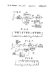
- FIG. 5 1 2 1 3 DECODER 580 l 103 5 TAPE BUFFER READER L BUFFER mi CLEAR 4O DECODER PRINTING FIGS gg FIG. 7
- This invention relates to an information recording apparatus capable of sufficiently simplifying the character input to a printing device and designating a margin for the recording paper thereby efficiently controlling the recording of characters.
- a printing device provided with a keyboard, for example a typewriter
- a charactor input button when a charactor input button is operated to print a character of a recording paper the operator designates the printing initiation position and generates orders for line shift and return of the printing head while watching the progress of printing of the characters on the recording paper. More particularly, the operator sets the printing initiation position (on the lefthand margin) and the printing termination position for the printing head in accordance with the width of the printing paper and when the printing operation proceeds to the printing termination position, the operator shifts the line and returns the printing head to the printing initiation position. Further, when the available space of the recording paper has been printed it is necessary to change the paper. For these reasons, the speed of typewriting is limited.
- Such a printing device is required to be provided with a platen mechanism for loading the recording paper, a mechanism for relatively stepping the platen and the printing head each time a character is printed, and a line shift mechanism at the time of return of the printing head. Due to these complicated mechanisms it is difficult to miniaturize the printing device convenient to carry.
- an object of this invention to provide an information recording apparatus capable of automatically designating predetermined left and right margins across the width of a recording paper in a printing device, thereby printing characters in the space between the designated margins.
- Another object of this invention is to provide an improved information recording apparatus of a compact construction that can repeatedly print a plurality of recording papers and can be readily used to form memorandams.
- Still another object of this invention is to provide an improved information recording apparatus in which the designated margin positions can be readily confirmed and varied.
- a further object of this invention is to provide an information recording apparatus of the type wherein the character information printed on a recording tape are automatically printed on a recording paper and when such information contain an error, such error can be readily corrected, and wherein an erasure or addition of the information can be readily made.
- an information recording apparatus comprising an input device for continuously recording on a tape shaped recording medium encoded character information and encoded printing position designating information which is used to define the printing format of the character information, means for successively reading out the code signals of the character information and of the printing position designation information from a tape shaped recording medium, margin designating means responsive to the read out printing position designating information for designating the left and right margins on a recording paper. and printing means for printing the read out character information on the recording paper in a space between the designated left and right margins.
- FIG. 1 is a block diagram illustrating a preferred embodiment of the information recording apparatus embodying the invention
- FIG. 2 is a plan view of a portion of an information recording tape prepared by the input device shown in FIG. 1;
- FIG. 3 is a block diagram showing the detail of the construction of the printing device shown in FIG. 1;
- FIG. 4 is a block diagram showing the detail of a temporary buffer memory and a decoder associated there with shown in FIG. 3;
- FIG. 5 is a block diagram showing a modified embodiment of this invention.
- FIG. 6 is a plan view showing a portion of the information recording tape prepared by the apparatus shown in FIG. 5;
- FIG. 7 is a block diagram showing another modification of this invention.
- FIG. 8 is a plan view showing a portion of the information recording tape prepared by the modified apparatus shown in FIG. 7.
- the embodiment of the information recording apparatus illustrated in FIG. 1 comprises an input device 12 including a character input section 11, an information recording tape 13 printed with the information from the character input section 11, and a printing device 14 for automatically printing the information recorded on the information recording tape 13 on a recording paper (not shown).
- the character input section 11 includes a keyboard (not shown) comprising a plurality of printing character selecting buttons corresponding to the input characters.
- the character input section 11 produces a character information signal which is encoded by an encoder 15 and the encoded signal is applied to a tape printer 16 which operates to successively print the codes corresponding to the input code signals on the tape 13.
- the tape printer 16 comprises a printing position designating means, a character generator for forming a character signal corresponding to the codes to be printed on the tape 13, and a printing mechanism for printing characters in accordance with the character signal.
- the input device 12 further comprises left and right margin buttons 17 and 18 for designating left and right margin settings of the recording paper, and a plurality of, for example 12 margin position designating buttons I, II, III XII for designating left and right margin positions.
- the margin position designating buttons I through XII are positioned with a spacing of 10 characters for example, that is at positions corresponding to 10, 20, 30, 40 th characters from the starting position.
- code signals corresponding to respective buttons are formed by the encoder 15 and these code signals as well as the corresponding marks and characters are printed on the recording tape 13 in the order mentioned above.
- the printing initiation position (left margin position) is firstly set by operating the left margin button 17, then the margin position designating button I is set, then the printing termination position (right margin position) is set by operating the right margin button 18 and then the margin position designating button XII. Thereafter, the character selecting button at the input section 11 is operated. Accordingly, code signals corre sponding to the operated buttons are printed on the tape 13 in the order of their operations.
- the code of the signal produced by the left margin button 17 is represented by (111110), that produced by the right margin button 18 by (111111), that by the margin position designating button I by (100001), and that by the margin position designating button XII by (101100). Then these codes are printed on the recording tape 13 as shown in FIG. 2, in which the bits shown by the long lines represent 1" and the bits shown by the short lines represent "0". The long and short lines are also used as clock bits.
- the selected keys in the keyboard at the input section 11 are operated to print digits 0, 1, 2 and 2, for example, then a period and finally alphabets T, H and E in the order mentioned.
- the position signals produced by the margin position designating buttons I through XII are coupled to the first to third memory devices 19, and 21 to be stored therein.
- Each of the memory devices 19 through 21 comprises a combination of a plurality of bit memory elements each connected to receive the corresponding bit of the position signals produced by respective margin position designating buttons.
- the memory devices 20 and 21 are constructed to change their contents according to the instructions given by the signals from AND gate circuits 22 and 23 whereas the memory device 19 is constructed to store all signals applied thereto. Further, the memory devices 19, 20 and 21 are constructed such that their contents are cleared by a clear signal generated when the tape printer 16 initiates a printing operation.
- a signal from a one-shot circuit 24 is applied to one input terminals of the AND gate circuits 22 and 23 and the one-shot circuit 24 is connected to be driven by the signal from an OR gate circuit 25 which is connected to receive the signals from the margin position designating buttons I through XII.
- the signals from the right and left margin buttons 18 and 17 are respectively coupled to the set terminal S and the reset terminal R of a flipflop circuit 26, and the signals from the set output terminal (Sand the reset output terminal Z of the flip-flop circuit 26 are coupled to the other input terminals of the AND gate circuits 22 and 23 to act as the gate signals.
- the position signals generated by the operations of the margin position designating buttons I through XII which are operated subsequent to the operation of the left margin button 17 are stored in the memory device 21 whereas the position signals generated by the margin position designating buttons I through XII which are operated subsequent to the operation of the right margin button 18 are stored in the memory device 20.
- Signals from corresponding memory bits of the memory devices 20 and 21 are grouped by corresponding one of 12 OR gate circuits 27-1 through 27-12 and the outputs of these OR gate circuits 27-1 through 27-12 are coupled to the display control circuit 29 of the display means 28-1 through 28-12 provided for respective margin position designating buttons I through XII, As shown, the display control circuit 29 is also connected to be controlled by the output of the memory device 19.
- a clear signal is produced by the tape printer 16 in response to the operation of the input section for clearing the contents of the memory devices 19, 20 and 21.
- the opposite end positions of the line to be printed which are determined in accordance with the width of the recording paper are designated by operating the left and right margin buttons 17 and 18 and the margin position designating buttons I through XII in a manner described hereinabove.
- the signals of the characters to be printed are applied to the character input section 11 for printing them on the recording tape 13 in the forms of codes and characters as shown in FIG. 2.
- the flipflop circuit 26 When the left margin button 17 is firstly operated, a signal is applied through the encoder 15 to the tape printer 16 in a manner described above, and the flipflop circuit 26 is reset thus applying a gate signal to the AND gate circuit 23. Under these conditions, when the margin position designating button I is operated, this button I provides a signal to the tape printer 16 and this signal drives the one-shot circuit 24 via the OR gate circuit 25 thus applying a write-in signal to the memory device 21 through the AND gate circuit 23 whereby the signal from the margin position designating button I is stored in the memory devices 19 and 21. Thereafter, when the right margin button 18 is operated, the flipflop circuit 26 is set to apply a gate signal to the AND gate circuit 22.
- the position designated thereby will be stored in the memory devices 19 and 20.
- the left and right margin operating positions are stored in the memory device 19 whereas the left and right designated margin positions are stored in the memory devices 20 and 21 respectively, so that the display control circuit 29 controlled by the memory devices 19, 20 and 21 operates display means 28-1 through 28-12 corresponding to the margin position designating buttons I through XII.
- the designated margin positions on the opposite ends of a line are displayed to be confirmed.
- the newly designated margin positions are displayed by the corresponding ones of the display elements 28-1 through 28-12, whereas the signal from the memory device 19 alone is displayed by the display means in a different manner.
- the display elements are operated normally, or lighted continuously, whereas when the logical-product signal from the memory device 20 or 21 is appeared, the display elements are flickered thus enabling to discriminate previously designated margin positions and the present margin positions.
- one of the margin positions that is only the left or right margin position is changed, only one of the margin position designating buttons corresponding to the position to be changed may be operated.
- the tape 13 prepared in this manner is supplied to a separate automatic printing device 14 where the coded signals recorded on the tape 13 are read out by a tape reader (not shown) provided in a main control device 30 thus forming data signals.
- the main control device 30 operates to detect the left and right signals corresponding to the operations of the left and right margin buttons 17 and 18, and the detected signals are coupled to the one input terminal of AND gate circuits 33 and 34 as the gate signals respectively through delay circuits 31 and 32.
- To the other input terminal of the AND gate circuits 33 and 34 are supplied margin signals generated by the main control device 30 following to the left and right signals so that these margin signals are stored in left and right margin position memory circuits 3S and 36, respectively.
- the main control device 30 is provided with a print control device 37 for performing the printing of the characters.
- a printing position control device 38 which controls the advancing operation of a printing head and a printing position memory device 39, in the form of a counter for example, for generating a position signal corresponding to the printing position.
- the signals generated by the left and right margin position memory circuits 35 and 36 are applied to coincidence circuits 40 and 41 together with the signal from the memory device 39, whereby when the position of the printing head and the left and right margin positions coincide with each other, command signals are applied to the main control device 30 and the printing position control device 38 for desig nating the line shift and return of the printing head as well as the return completion position thus printing the characters at the predetermined portion of the recording paper.
- the main control device 30, the printing control device 37 and the printing position control de vice 38 cooperate to constitute a control section 42.
- this recording system is suitable for a stereograph typewriter. According to this system, it is only necessary to prepare a tape recorded with code signals corresponding to the input character signals so that it is possible to greatly reduce the size and weight of the input device thus enabling to manufacture small portable recording devices which can be used to take memorandams. Further, where characters or symbols corresponding to the coded signals are recorded on the tape together with the code signals it is easy to correct errors by a proper edition of the recorded tape, thereby increasing the efficiency of the printing operation. Particularly, it is very advantageous because the printing of the recording paper in the printing device can be made automatically.
- left and right margin buttons 17 and 18 are shown separate from the character input section 11, it will be clear that these members can be constructed as an integral unit. Further, by prescribing the order of the operations of the left and right margin settings, the number of such buttons can be reduced to one. Three memory devices 19, 20 and 21 can also be substituted by a single memory device. Where the margin position designating buttons are arranged by taking into consideration the actual width of the recording paper, it is possible to readily imagine the actual printing position on the recording paper.
- FIG. 1 The detail of the automatic printing device 14 shown in FIG. 1 will be described with reference to FIGS. 3 and 4, in which elements corresponding to those shown in FIG. 1 are designated by the same reference numerals.
- the tape 13 has been recorded with information as shown in FIG. 2.
- This tape 13 is mounted on a tape reader 50 in the control section 42.
- the tape reader 50 may be a well known optical character reader, and produces, for example, 6 bit code signals corresponding to groups of long and short lines shown in FIG. 2.
- this circuit 52 While the printing is not performed as the 1 output from an inverter 53 is given to the other input of the AND gate circuit 52, this circuit 52 provides a 1 output.
- this 1 output is applied to the start terminal of the tape reader 50 it will commence to read the information recorded on the tape 13. Then, the tape reader 50 simultaneously applies a six-bit coded signal (111110) corresponding to the left margin designating command signal to a buffer register 54 and a decoder 56.
- the decoder 56 operates to decode the code signal (111110) to produce an output which is coupled to one input of the AND gate circuit 33 via delay circuits 31 and 57.
- the tape reader 50 applies to the other input of the AND gate circuit 33 through a buffer register 54 a signal representing the th character position from the starting position of the printing head so that this signal is stored in a left margin designating counter 35.
- the tape reader 50 sends a six-bit code signal (111111) corresponding to the right margin designat' ing command signal to the decoder 56 and the signal decoded thereby is applied to one input of the AND gate circuit 34 via delay circuits 32 and 58.
- a signal corresponding to the right margin designating button Xll situated at the 120th character position from the starting position of the printing head is sent to the other input of the AND gate circuit 34 from the tape reader 50 via buffer register 54 so that this signal is stored in the right margin designating counter 36.
- the tape reader 50 supplies a six-bit signal (001010) corresponding to the digit 0 shown in FIG. 2 t0 the decoder 56 via buffer register 54.
- the decoder 56 operates to apply a character information detection signal to one input of an AND gate circuit 59, the other input thereof being connected to receive a 1 signal from an inverter 61 where it does not receive any signal from either one of delay circuits 31, 32, 57 and 58 via an OR gate circuit 60.
- the AND gate circuit 59 applies a write-in instruction signal to the control terminal of the buffer register 55 thus transferring a six-bit signal contained in the buffer register 54 and corresponding to the digit 0 into the buffer register 55.
- the signal which has been stored in the buffer register 55 is applied to printing apparatus 62 as a printing data. Further. the output from the AND gate circuit 59 is applied to the input of a delay circuit 63 for producing a printing commanding signal from the output of the delay circuit 63. This printing commanding signal is also applied to the printing apparatus 62.
- an output is also applied to one input of an OR gate circuit 65 from a one-shot circuit 64 thus causing inverter 53 to produce an output 0. Consequently, the operation of the tape reader 50 is stopped so long as the one-shot circuit 64 produces an output.
- the flip-flop circuit 67 When the output of the delay circuit 57 is applied to the AND gate circuit 33, this output is also applied to the set terminal 8 of a flip-flop circuit 67 via an OR gate circuit 66. In response to this signal, the flip-flop circuit 67 is set to produce a Q output which is sent to the printing position counter 39 to act as the reset signal thus clearing the counter 39 and to the printing apparatus 62 to act as the return signal. In response to this return signal, the printing head (not shown) of the printing apparatus 62 is returned to its starting position at the lefthand end of the printing range.
- a return detecting switch 68 provided with the printing apparatus 62 for detecting the return of the printing head to the starting position is closed to apply a signal to the reset terminal R of a flip-flop circuit 67 thus extinguishing the return signal from this flip flop circuit 67.
- the return signal is also applied to one input of the OR gate circuit 65 via OR gate circuit 69 so as to stop the operation of the tape reader 50 while the printing head is being returned to the starting position.
- the inverter 70 produces an output 1.
- both inputs to the AND gate circuit 71 are 1 whereby the flip-flop circuit 72 is set to apply an advancing signal to the printing head of the printing apparatus 62.
- This advancing signal is also sent to the printing position counter 39 through an OR gate circuit 73. Consequently, the printing head advances forwardly from its starting position, and the content of the printing position counter 39 is increased one by one. This advancing motion is continued until the content of the counter 39 comes to coincide with the designated position (10) from the left margin position counter 35.
- the coincidence circuit 41 produces an output which is applied to the reset terminal R of the flip-flop circuit 72 thus resetting the same. Then, the flip-flop circuit 72 terminates the advancing signal whereby the printing head stops at a position corresponding to the left margin position designating button I, that is at the position of the 10th character from the starting position.
- the flip-flop circuit 72 terminates the advancing signal whereby the printing head stops at a position corresponding to the left margin position designating button I, that is at the position of the 10th character from the starting position.
- the output from the delay circuit 57 it is also possible to print a return commanding information on the recording tape 13 in front of the margin position designating information h
- Such a return commanding information is decoded by the decoder 56 and is then applied to the OR gate circuit 66 via delay circuit 74 to act as the return commanding signal.
- the margin position designating operation has already been completed and none of the delay circuits 31, 32, 57 and 58 produces an output so that the inverter 61 produces an output 1. Accordingly, an output is produced by the AND gate circuit 59 while the decoder 56 is producing a printing information detecting signal.
- the delay circuit 63 provides a printing commanding signal to the printing apparatus 62, whereby this apparatus 62 prints the printing data from the buffer register 55 on the recording paper. For example, the first character 0 shown in FIG. 2 is printed.
- the printing commanding signal drives the one-shot circuit 64 for producing a signal which interrupts the operation of the tape reader 50.
- the output from the oneshot circuit 64 also drives another one-shot circuit 78 comprising an inverter 75, a delay circuit 76 and an AND gate circuit 77.
- the latter one-shot circuit 78 provides a pulse output which builds up concurrently with the disappearance of the output from the one-shot circuit 64 to the printing position counter 39 via the OR gate circuit 73 to act as an activating signal.
- the content of the counter 39 is reduced to zero while at the same time the printing head is returned to the starting position.
- the printing of the next line is performed in the same manner according to the printing information recorded on the tape 13.
- the printing line is shifted one line when the printing head is returned to the starting position for printing the characters on the next line.
- a switch 79 of the printing apparatus 62 is provided at this position for detecting the arrival of the printing head to the right most position of the printing region.
- the switch 79 is closed when the printing head arrives at the right most position to provide a set signal to the flip-flop circuit 67 via the OR gate circuit 66, thus producing a return signal for returning the printing head to the starting position.
- a termination code may be printed on the recording tape 13 when required.
- the decoder 56 provides a termination signal which is applied to the reset terminal R of flip-flop circuit 51 through a delay circuit 80.
- the flip-flop circuit 51 is reset to disenable the AND gate circuit 52 thereby stopping the operation of the tape reader 50. Under these conditions the recording paper is exchanged and when a start signal is applied to the set terminal of the flip-flop circuit 51, the printing operation is resumed.
- the code signal (111110) of the left margin designating commanding code is read out.
- the tape reader 50 produces clock signals corresponding to respective code bits printed on the recording tape 13 as shown in FIG. 2 and these clock signals are applied to a scale-of-6 counter 81 and to respective clock pulse input terminals of 6 memory elements 54-1 through 54-6 which consist of the buffer register 54.
- the memory elements 54-1 through 54-6 are constructed to store successively the bits of the code signal (111110), for example in response to the clock pulses starting from the least significant bit.
- the counter 81 When the six-bit signal is read out the counter 81 produces a carry signal which is applied to an AND gate circuit 82 together with the clock signal corresponding to the last bit (sixth bit) of a code signal. Accordingly, the AND gate circuit 82 produces an output each time the read out operation of one code signal is completed, and this output is applied to respective output control terminals of delay circuits 3] and 32 and to one input of AND gate circuits 83, 84 and 85.
- inverter 86 When a left margin commanding code signal (111110) exists at each input side of the memory elements 54-1 through 54-6, inverter 86 produces an output 1 so that the AND gate circuit 87 in the decoder 56 provides an output for the delay circuit 31.
- the AND gate circuit 88 is enabled to enable an AND gate circuit 89 so as to apply its output to the delay circuit 32.
- the return commanding code for the printing head is (111101 an inverter 90 produces an output I because the memory element 54-4 provides an output 0 so that a return signal is sent to the delay circuit 74 shown in FIG. 3 via AND gate circuit 83.
- (000000) represents the printing termination code
- a 0 signal is sent to an inverter 92 via an OR gate circuit 91 so that an AND gate circuit 85 is enabled for sending the printing termination signal to the delay circuit 80 shown in FIG. 3 via the AND gate circuit 85.
- an inverter 94 connected to the output terminal of the OR gate circuit 93 and an inverter 96 connected to the output terminal of an OR gate circuit respectively produce an output 1 so that the output of an AND gate circuit 97 is applied to one input of AND gate circuit 84.
- a printing information detection output is sent to the AND gate circuit 59 via the AND gate circuit 84.
- the output of the AND gate circuit 59 is applied as a write-in commanding signal to the respective memory control terminals of six memory elements 55-1 through 55-6 which constitute the buffer register 55 shown in FIG. 3.
- the memory elements 55-1 through 55-6 store simultaneously the 6 bit character information from the buffer register 54.
- the outputs from the memory elements 55-1 through 55-6 are supplied to the printing apparatus 62 shown in FIG. 3 to act as the printing data.
- the information recorded on the recording tape 13 contains an error. It is necessary to detect such error by watching the printed information when performing automatic printing by using the tape 13. More particularly, it is necessary to remove the portion of the printed information containing the error by stopping the printing device. Thus, it is necessary to continuously watch the printed tape 13 to find out the errors. When an error is overlooked, the information containing the error will be printed.
- the embodiment shown in FIG. 5 obviates such difficulty and is constructed such that when the information printed on the recording tape 13 contains any error which must be corrected, such error is automatically detected and deleted at the time of the automatic printmg.
- the buffer register 54a shown in FIG. 5 stores information interleaved with space codes. for example three character information T.H. and E. Upon completion of the printing of these characters. the information stored in the buffer register 54a are cleared by a clear signal supplied thereto from the printing apparatus 62a.
- the character information printed on the tape 13 contain an error code signal. printing thereof is prevented, it is also possible to substitute a stop code signal for the error code signal so as to stop the operation of the printing apparatus when the stop code signal is detected and to manually print a correct character if desired.
- the use of the stop code signal is also efficient in such automatic printing of direct mails, for example. where only the addresses are different but the body of the communication is the same. In such an application, a stop code signal is inserted at a position immediately prior to respective address. Then it is possible to print a plurality of communication of the same content by merely manually printing the addresses each time the operation of the printing apparatus is stopped.
- FIG. 7 illustrates one example of a printing device 1417 designed to use a recording tape 13 printed with such stop code signals.
- the tape utilized in this modified embodiment is printed with character information as shown in FIG. 8.
- the codes representing the digits 0, 1 and 2 printed on the tape 13 are the same as those shown in FIG. 2, and the space code S following the digit 0 is the same as that shown in FIG. 6, that is (011100).
- a stop code (111100) is printed between digit 2 and character A.
- this stop code is different from the space code (011100) in that the most significant bit 0 thereof is substituted by 1 it is easy to convert the space code into the stop code (111100) by elongating the short line corresponding to the most significant bit of the space code printed on the tape 13.
- the portion of the tape including the short line may be colored black so long as a code equivalent to a code (111100) can be obtained.
- the tape 13 prepared in this manner is loaded in the tape reader 50 and thereafter a start signal is applied to a tape feeder 111 from a key input device so as to successively read out the information on the tape 13 by means of the tape read out device 1 12.
- the information thus read out are sent to a buffer register 101 through an OR gate circuit 113.
- a decoder 102 detects a signal corresponding to the space code S
- the content of the buffer register 101 is transferred into another buffer register 54a via an AND gate circuit 103 and stored in a buffer register 54a, in the same manner as has been described in connection with FIG. 5.
- the information stored in the buffer register 540 are printed on the recording paper in the same manner as in FIG. 5.
- this stop code is decoded by a decoder 114 so that this decoder 114 supplies a tape feed stopping commanding signal to the tape feeder 111.
- a clear signal is sent to the buffer register 101 from the key input device 110 to clear the content stored in the buffer register 101. Thereafter, a new character information is applied to the buffer register 101 from the key input device 110 through the OR gate circuit 113.
- the decoder 102 When a space code is sent to the buffer register 101 from the key input device 110 subsequent to the character information, the decoder 102 produces an output which enables the AND gate circuit 103 thereby transferring the character information just applied to the buffer register 101 from the key input device 110 into the buffer register 54a. It is also possible to print a new character by the manual operation of the printing apparatus after stopping the operation of tape feeder 111 by applying thereto a stop code. In this case, instead of applying the necessary character information from the key input device 110 it is possible to print the characters on the re cording paper by the manual operation of the keyboard provided with the printing apparatus 62 shown in FIG. 3. After printing the new character by sending a start signal to the tape feeder 111 from the key input device 110 characters A and B can be printed succeeding to characters 1, 2 and 2 as shown in FIG. 8.
- An automatic information recording apparatus comprising:
- an input device for recording on a tape-shaped recording medium first encoded printing position designating information used to define the first and last printing positions ofa single line in order to define a printing format, and then for recording on said tape-shaped recording medium encoded character information continuously regardless of the defined printing format;
- first memory means coupled to said reading-out means for storing the printing position designating information read out by said reading-out means
- a printing device coupled to said reading-out means for printing on a recording paper the character information read out by said reading-out means
- second memory means for storing the last printing position of each line printed by said printing device
- a comparator coupled to said first and second memory means for comparing the content of the second memory means with that of the first memory means
- said input device includes means for printing function codes for separating word units on said tape-shaped recording medium; and said printing device comprises a buffer memory device coupled to said reading-out means for temporarily storing respective word units of the information read out by said reading-out means, means for detecting the function codes contained in the information read out by said reading-out means, and means responsive to the detected function codes for reading out and printing the word unit information which has been stored in said buffer memory device.
- An automatic information recording apparatus comprising means for recording function codes for separating word units on said tape-shaped recording medium, and error code input means for erasing erroneous character information when such erroneous character information is received; and said printing device comprises a buffer memory device coupled to said reading-out means for temporarily storing respective word units of the information produced by said reading-out means, means coupled to said buffer memory device for reading out and printing respective word units of the information from said buffer memory device, means for detecting error codes contained in the information read out by said reading-out means, and means coupled to said detecting means and to said buffer memory device and responsive to a detected error code for erasing a corresponding word from said buffer memory device.
- said input device comprises means for recording function codes for separating word units on said tape-shaped recording medium, the function codes recorded on said recording medium being constructed such that any function code can be manually converted into a stop code
- said printing means comprises a buffer memory device coupled to said reading-out means for storing respective word units of the information produced by said reading-out means, means coupled to said buffer memory device for reading out and printing respective word units of the information from said buffer memory device, means for detecting a stop code contained in the information read out by said reading-out means, and means responsive to the detected stop code for stopping the reading out of the information from said recording medium.
- An automatic information recording apparatus according to claim 1 wherein said input device is constructed separately and is freely movable relative to the remainder of the apparatus.
- margin memory means for storing left and right margin information contained in said printing position designating information
Landscapes
- Record Information Processing For Printing (AREA)
- Printers Characterized By Their Purpose (AREA)
Abstract
The information recording apparatus comprises an input device for continuously printing on a recording tape encoded character information and encoded left and right margin position designating information which is used to determine the width of a space on a recording paper in which the encoded character information is to be printed; and a printing device having means for designating the left and right margin positions of a printing device on the recording paper in accordance with the left and right margin position designating information recorded on the recording tape, and a printing means for printing characters in a space on the recording paper between the designated left and right margin positions in accordance with the encoded character information printed on the recording tape.
Description
Umted States Patent 1 1 1111 3,923,137 Kashio 1 1 Dec. 2, 1975 1541 INFORMATION RECORDING APPARATUS 3,812,945 5/1974 Koplow ct al 197/19 7 [75] or: os Ka o, yo Japa 3.8.3.389 7/[974 He1tmt1n et a]. 197/19 X 1731 Assignee: Casio Computer Co., Ltd., Tokyo, Primary Examiner-J. Reed Fisher Japan Assistant Examiner-R. T. Rader Filed: Mar- 1974 Attorney, Agent, or F1'rm-Flynn & Frishauf [211 App]. No.: 456,281 [57] ABSTRACT The information recording apparatus comprises an 30 Foreign A li fi priority Data input device for continuously printing on a recording Apr 5 [973 Japan N 4868221 tape encoded character information and encoded left Apr 5. 1973 Japan 48-38222 margm 'i des'gnaung mformm'on App 5 973 Japan] N 4838223 wh1ch 1s used to determine the wldth of a space on a recording paper in which the encoded character infor- 52 U.S. c1. 197/19; 197/20; 340/1725 math) is m and Priming having [51] Int. Cl. B4lJ 5/30 means for the left and 58 Field of Search 197/19, 20, 84 R, 84 A. T' '1" recofdmg R fl 197/84 B; 101/93 C; 340/1725 17A! cordance w1th the left and rlght margm posltlon deslgnatmg 1nformat1on recorded on the recordmg tape. [56] References Cited zindtzli1 printingdmeans for iririting chliraeiters in tsipzllcfe on e recor mg paper e ween e eslgna e e UNITED STATES PATENTS and right margin positions in accordance with the eng' Y Y r r coded character information printed on the recording t ernler t 3.674.125 7/1972 Kolpek 340/1741 X tape- 3,78[),846 12/1973 Kolpck et a1. 197/19 6 Claims, 8 Drawing Figures COINCIDENCE CIRCUIT |-IIX]I O122.THE
TAPE READER COUNTER US. Patent Dec. 2, 1975 Sheet 3 of4 3,923,137
US. Patent Dec. 2, 1975 Sheet 4 of4 3,923,137
FIG. 5 1 2 1 3 DECODER 580 l 103 5 TAPE BUFFER READER L BUFFER mi CLEAR 4O DECODER PRINTING FIGS gg FIG. 7
DEV CE 3 {oi I BUFFER 1/ BUFFER s DECODER DECODER FIG.8
1 Hill] IIIIII I|HII Illlll llllll Hll'l "HI! IIIHI MIN} INFORMATION RECORDING APPARATUS This invention relates to an information recording apparatus capable of sufficiently simplifying the character input to a printing device and designating a margin for the recording paper thereby efficiently controlling the recording of characters.
In a printing device provided with a keyboard, for example a typewriter, when a charactor input button is operated to print a character of a recording paper the operator designates the printing initiation position and generates orders for line shift and return of the printing head while watching the progress of printing of the characters on the recording paper. More particularly, the operator sets the printing initiation position (on the lefthand margin) and the printing termination position for the printing head in accordance with the width of the printing paper and when the printing operation proceeds to the printing termination position, the operator shifts the line and returns the printing head to the printing initiation position. Further, when the available space of the recording paper has been printed it is necessary to change the paper. For these reasons, the speed of typewriting is limited. Moreover, such a printing device is required to be provided with a platen mechanism for loading the recording paper, a mechanism for relatively stepping the platen and the printing head each time a character is printed, and a line shift mechanism at the time of return of the printing head. Due to these complicated mechanisms it is difficult to miniaturize the printing device convenient to carry.
Accordingly, it is an object of this invention to provide an information recording apparatus capable of automatically designating predetermined left and right margins across the width of a recording paper in a printing device, thereby printing characters in the space between the designated margins.
Another object of this invention is to provide an improved information recording apparatus of a compact construction that can repeatedly print a plurality of recording papers and can be readily used to form memorandams.
Still another object of this invention is to provide an improved information recording apparatus in which the designated margin positions can be readily confirmed and varied.
A further object of this invention is to provide an information recording apparatus of the type wherein the character information printed on a recording tape are automatically printed on a recording paper and when such information contain an error, such error can be readily corrected, and wherein an erasure or addition of the information can be readily made.
SUMMARY OF THE INVENTION According to this invention these and other objects can be accomplished by providing an information recording apparatus comprising an input device for continuously recording on a tape shaped recording medium encoded character information and encoded printing position designating information which is used to define the printing format of the character information, means for successively reading out the code signals of the character information and of the printing position designation information from a tape shaped recording medium, margin designating means responsive to the read out printing position designating information for designating the left and right margins on a recording paper. and printing means for printing the read out character information on the recording paper in a space between the designated left and right margins.
BRIEF DESCRIPTION OF THE DRAWINGS Further objects and advantages of the invention can be more fully understood from the following detailed description taken in conjunction with the accompanying drawings, in which:
FIG. 1 is a block diagram illustrating a preferred embodiment of the information recording apparatus embodying the invention;
FIG. 2 is a plan view of a portion of an information recording tape prepared by the input device shown in FIG. 1;
FIG. 3 is a block diagram showing the detail of the construction of the printing device shown in FIG. 1;
FIG. 4 is a block diagram showing the detail of a temporary buffer memory and a decoder associated there with shown in FIG. 3;
FIG. 5 is a block diagram showing a modified embodiment of this invention;
FIG. 6 is a plan view showing a portion of the information recording tape prepared by the apparatus shown in FIG. 5;
FIG. 7 is a block diagram showing another modification of this invention; and
FIG. 8 is a plan view showing a portion of the information recording tape prepared by the modified apparatus shown in FIG. 7.
DETAILED DESCRIPTION OF ILLUSTRATED EMBODIMENTS The embodiment of the information recording apparatus illustrated in FIG. 1 comprises an input device 12 including a character input section 11, an information recording tape 13 printed with the information from the character input section 11, and a printing device 14 for automatically printing the information recorded on the information recording tape 13 on a recording paper (not shown). The character input section 11 includes a keyboard (not shown) comprising a plurality of printing character selecting buttons corresponding to the input characters. The character input section 11 produces a character information signal which is encoded by an encoder 15 and the encoded signal is applied to a tape printer 16 which operates to successively print the codes corresponding to the input code signals on the tape 13.
The tape printer 16 comprises a printing position designating means, a character generator for forming a character signal corresponding to the codes to be printed on the tape 13, and a printing mechanism for printing characters in accordance with the character signal.
The input device 12 further comprises left and right margin buttons 17 and 18 for designating left and right margin settings of the recording paper, and a plurality of, for example 12 margin position designating buttons I, II, III XII for designating left and right margin positions. Assuming that the printing device 14 is set to print 125 characters per line the margin position designating buttons I through XII are positioned with a spacing of 10 characters for example, that is at positions corresponding to 10, 20, 30, 40 th characters from the starting position. Thus, where it is desired to print the characters between th and 120th character positions, for example, it is necessary to operate the buttons of the input device 12 in the order of left margin button 17, designating button I, right margin button 18, and designating button XII. By the operations of these buttons, code signals corresponding to respective buttons are formed by the encoder 15 and these code signals as well as the corresponding marks and characters are printed on the recording tape 13 in the order mentioned above.
Actually, the printing initiation position (left margin position) is firstly set by operating the left margin button 17, then the margin position designating button I is set, then the printing termination position (right margin position) is set by operating the right margin button 18 and then the margin position designating button XII. Thereafter, the character selecting button at the input section 11 is operated. Accordingly, code signals corre sponding to the operated buttons are printed on the tape 13 in the order of their operations.
Let us now assume that the code of the signal produced by the left margin button 17 is represented by (111110), that produced by the right margin button 18 by (111111), that by the margin position designating button I by (100001), and that by the margin position designating button XII by (101100). Then these codes are printed on the recording tape 13 as shown in FIG. 2, in which the bits shown by the long lines represent 1" and the bits shown by the short lines represent "0". The long and short lines are also used as clock bits. After operating the margin position designating button XII, the selected keys in the keyboard at the input section 11 are operated to print digits 0, 1, 2 and 2, for example, then a period and finally alphabets T, H and E in the order mentioned. The codes and the corresponding characters printed with these character inputs are shown in FIG. 2. Thereafter, successive character input information is continuously printed on the tape 13. As described hereinabove, the margin designating positions were assumed herein to be spaced from each other by 10 characters, but the spacing may be decreased to 5 characters in which case it is necessary to provide 24 designating buttons. Although it is possible to provide one designating button at each printing position, that is 125 buttons in this case, such arrangement complicates the construction and is not practical.
The position signals produced by the margin position designating buttons I through XII are coupled to the first to third memory devices 19, and 21 to be stored therein. Each of the memory devices 19 through 21 comprises a combination of a plurality of bit memory elements each connected to receive the corresponding bit of the position signals produced by respective margin position designating buttons. The memory devices 20 and 21 are constructed to change their contents according to the instructions given by the signals from AND gate circuits 22 and 23 whereas the memory device 19 is constructed to store all signals applied thereto. Further, the memory devices 19, 20 and 21 are constructed such that their contents are cleared by a clear signal generated when the tape printer 16 initiates a printing operation. A signal from a one-shot circuit 24 is applied to one input terminals of the AND gate circuits 22 and 23 and the one-shot circuit 24 is connected to be driven by the signal from an OR gate circuit 25 which is connected to receive the signals from the margin position designating buttons I through XII. The signals from the right and left margin buttons 18 and 17 are respectively coupled to the set terminal S and the reset terminal R of a flipflop circuit 26, and the signals from the set output terminal (Sand the reset output terminal Z of the flip-flop circuit 26 are coupled to the other input terminals of the AND gate circuits 22 and 23 to act as the gate signals. The position signals generated by the operations of the margin position designating buttons I through XII which are operated subsequent to the operation of the left margin button 17 are stored in the memory device 21 whereas the position signals generated by the margin position designating buttons I through XII which are operated subsequent to the operation of the right margin button 18 are stored in the memory device 20.
Signals from corresponding memory bits of the memory devices 20 and 21 are grouped by corresponding one of 12 OR gate circuits 27-1 through 27-12 and the outputs of these OR gate circuits 27-1 through 27-12 are coupled to the display control circuit 29 of the display means 28-1 through 28-12 provided for respective margin position designating buttons I through XII, As shown, the display control circuit 29 is also connected to be controlled by the output of the memory device 19.
With the input device 12 constructed as described above, at the time of initiating the printing of the characters, a clear signal is produced by the tape printer 16 in response to the operation of the input section for clearing the contents of the memory devices 19, 20 and 21. The opposite end positions of the line to be printed which are determined in accordance with the width of the recording paper are designated by operating the left and right margin buttons 17 and 18 and the margin position designating buttons I through XII in a manner described hereinabove. Then the signals of the characters to be printed are applied to the character input section 11 for printing them on the recording tape 13 in the forms of codes and characters as shown in FIG. 2. When the left margin button 17 is firstly operated, a signal is applied through the encoder 15 to the tape printer 16 in a manner described above, and the flipflop circuit 26 is reset thus applying a gate signal to the AND gate circuit 23. Under these conditions, when the margin position designating button I is operated, this button I provides a signal to the tape printer 16 and this signal drives the one-shot circuit 24 via the OR gate circuit 25 thus applying a write-in signal to the memory device 21 through the AND gate circuit 23 whereby the signal from the margin position designating button I is stored in the memory devices 19 and 21. Thereafter, when the right margin button 18 is operated, the flipflop circuit 26 is set to apply a gate signal to the AND gate circuit 22. Then, when one of the margin position designating buttons, for example button XII, is operated, the position designated thereby will be stored in the memory devices 19 and 20. Thus, the left and right margin operating positions are stored in the memory device 19 whereas the left and right designated margin positions are stored in the memory devices 20 and 21 respectively, so that the display control circuit 29 controlled by the memory devices 19, 20 and 21 operates display means 28-1 through 28-12 corresponding to the margin position designating buttons I through XII. In other words, the designated margin positions on the opposite ends of a line are displayed to be confirmed.
While the signals of the characters to be printed are being continuously applied to the character input section 11, when it is is desired to change the printing position on the recording paper, margin buttons 17 and 18 are operated again and two margin position designating buttons corresponding to the left and right margins at the opposite ends of the newly selected printing width are operated. As a result of this operation, newly designated margin positions are printed on the tape 13 and these positions are written in the memory device 19 in addition to the previously designated positions, and the contents of the memory devices 20 and 21 are changed with the new margin positions in response to the signals from the AND gate circuits 22 and 23. As a result, to the display control circuit 29 are applied with the new margin position signals from the memory devices 20 and 21 together with the all margin position signals which have been already written in the memory device 19. In this manner, by the logical-product action of the signals from the memory device 19 and the memory device 20 or 21, the newly designated margin positions are displayed by the corresponding ones of the display elements 28-1 through 28-12, whereas the signal from the memory device 19 alone is displayed by the display means in a different manner. For example, when the signal from only the memory device 19 is present, the display elements are operated normally, or lighted continuously, whereas when the logical-product signal from the memory device 20 or 21 is appeared, the display elements are flickered thus enabling to discriminate previously designated margin positions and the present margin positions. Where one of the margin positions, that is only the left or right margin position is changed, only one of the margin position designating buttons corresponding to the position to be changed may be operated.
The tape 13 prepared in this manner is supplied to a separate automatic printing device 14 where the coded signals recorded on the tape 13 are read out by a tape reader (not shown) provided in a main control device 30 thus forming data signals. The main control device 30 operates to detect the left and right signals corresponding to the operations of the left and right margin buttons 17 and 18, and the detected signals are coupled to the one input terminal of AND gate circuits 33 and 34 as the gate signals respectively through delay circuits 31 and 32. To the other input terminal of the AND gate circuits 33 and 34 are supplied margin signals generated by the main control device 30 following to the left and right signals so that these margin signals are stored in left and right margin position memory circuits 3S and 36, respectively. Further, the main control device 30 is provided with a print control device 37 for performing the printing of the characters. a printing position control device 38 which controls the advancing operation of a printing head and a printing position memory device 39, in the form of a counter for example, for generating a position signal corresponding to the printing position. The signals generated by the left and right margin position memory circuits 35 and 36 are applied to coincidence circuits 40 and 41 together with the signal from the memory device 39, whereby when the position of the printing head and the left and right margin positions coincide with each other, command signals are applied to the main control device 30 and the printing position control device 38 for desig nating the line shift and return of the printing head as well as the return completion position thus printing the characters at the predetermined portion of the recording paper. The main control device 30, the printing control device 37 and the printing position control de vice 38 cooperate to constitute a control section 42.
With the input device 12, once the left and right margin positions are designated in accordance with the width of the recording paper it is possible to continuously apply the signals of the characters to be printed thus greatly simplifying the printing operation. For this reason, this recording system is suitable for a stereograph typewriter. According to this system, it is only necessary to prepare a tape recorded with code signals corresponding to the input character signals so that it is possible to greatly reduce the size and weight of the input device thus enabling to manufacture small portable recording devices which can be used to take memorandams. Further, where characters or symbols corresponding to the coded signals are recorded on the tape together with the code signals it is easy to correct errors by a proper edition of the recorded tape, thereby increasing the efficiency of the printing operation. Particularly, it is very advantageous because the printing of the recording paper in the printing device can be made automatically.
Further, it is possible to display the initially designated printing position concurrently with the designation thereof, so that it is possible to apply the character signals to the character input section while considering the printing condition of the recording paper in the printing device thus enabling more efficient utilization of the information recording apparatus.
Although the left and right margin buttons 17 and 18 are shown separate from the character input section 11, it will be clear that these members can be constructed as an integral unit. Further, by prescribing the order of the operations of the left and right margin settings, the number of such buttons can be reduced to one. Three memory devices 19, 20 and 21 can also be substituted by a single memory device. Where the margin position designating buttons are arranged by taking into consideration the actual width of the recording paper, it is possible to readily imagine the actual printing position on the recording paper.
The detail of the automatic printing device 14 shown in FIG. 1 will be described with reference to FIGS. 3 and 4, in which elements corresponding to those shown in FIG. 1 are designated by the same reference numerals. Let us assume that the tape 13 has been recorded with information as shown in FIG. 2. This tape 13 is mounted on a tape reader 50 in the control section 42. The tape reader 50 may be a well known optical character reader, and produces, for example, 6 bit code signals corresponding to groups of long and short lines shown in FIG. 2. Upon application of a start signal to the set terminal S of a flip-flop circuit 51, the 0 output thereof is applied to one input of an AND gate circuit 52. While the printing is not performed as the 1 output from an inverter 53 is given to the other input of the AND gate circuit 52, this circuit 52 provides a 1 output. When this 1 output is applied to the start terminal of the tape reader 50 it will commence to read the information recorded on the tape 13. Then, the tape reader 50 simultaneously applies a six-bit coded signal (111110) corresponding to the left margin designating command signal to a buffer register 54 and a decoder 56. The decoder 56 operates to decode the code signal (111110) to produce an output which is coupled to one input of the AND gate circuit 33 via delay circuits 31 and 57. Then, corresponding to the margin position designating button l, the tape reader 50 applies to the other input of the AND gate circuit 33 through a buffer register 54 a signal representing the th character position from the starting position of the printing head so that this signal is stored in a left margin designating counter 35.
Then. the tape reader 50 sends a six-bit code signal (111111) corresponding to the right margin designat' ing command signal to the decoder 56 and the signal decoded thereby is applied to one input of the AND gate circuit 34 via delay circuits 32 and 58. Next, a signal corresponding to the right margin designating button Xll situated at the 120th character position from the starting position of the printing head is sent to the other input of the AND gate circuit 34 from the tape reader 50 via buffer register 54 so that this signal is stored in the right margin designating counter 36.
Then, the tape reader 50 supplies a six-bit signal (001010) corresponding to the digit 0 shown in FIG. 2 t0 the decoder 56 via buffer register 54. Where the input code signal corresponds to a character information the decoder 56 operates to apply a character information detection signal to one input of an AND gate circuit 59, the other input thereof being connected to receive a 1 signal from an inverter 61 where it does not receive any signal from either one of delay circuits 31, 32, 57 and 58 via an OR gate circuit 60. In response to this 1 signal, the AND gate circuit 59 applies a write-in instruction signal to the control terminal of the buffer register 55 thus transferring a six-bit signal contained in the buffer register 54 and corresponding to the digit 0 into the buffer register 55. The signal which has been stored in the buffer register 55 is applied to printing apparatus 62 as a printing data. Further. the output from the AND gate circuit 59 is applied to the input of a delay circuit 63 for producing a printing commanding signal from the output of the delay circuit 63. This printing commanding signal is also applied to the printing apparatus 62. When the printing commanding signal is obtained from the delay circuit 63, an output is also applied to one input of an OR gate circuit 65 from a one-shot circuit 64 thus causing inverter 53 to produce an output 0. Consequently, the operation of the tape reader 50 is stopped so long as the one-shot circuit 64 produces an output.
When the output of the delay circuit 57 is applied to the AND gate circuit 33, this output is also applied to the set terminal 8 of a flip-flop circuit 67 via an OR gate circuit 66. In response to this signal, the flip-flop circuit 67 is set to produce a Q output which is sent to the printing position counter 39 to act as the reset signal thus clearing the counter 39 and to the printing apparatus 62 to act as the return signal. In response to this return signal, the printing head (not shown) of the printing apparatus 62 is returned to its starting position at the lefthand end of the printing range. Then, a return detecting switch 68 provided with the printing apparatus 62 for detecting the return of the printing head to the starting position is closed to apply a signal to the reset terminal R of a flip-flop circuit 67 thus extinguishing the return signal from this flip flop circuit 67. The return signal is also applied to one input of the OR gate circuit 65 via OR gate circuit 69 so as to stop the operation of the tape reader 50 while the printing head is being returned to the starting position.
Since the left margin designating position corresponds to the 10th character position from the starting position of the printing head, when the printing head occupies the starting position and hence the content of the printing position counter 39 is zero, the coincidence circuit 41 will not produce any output. Accordingly, the inverter 70 produces an output 1. Thus, both inputs to the AND gate circuit 71 are 1 whereby the flip-flop circuit 72 is set to apply an advancing signal to the printing head of the printing apparatus 62. This advancing signal is also sent to the printing position counter 39 through an OR gate circuit 73. Consequently, the printing head advances forwardly from its starting position, and the content of the printing position counter 39 is increased one by one. This advancing motion is continued until the content of the counter 39 comes to coincide with the designated position (10) from the left margin position counter 35. Upon coincidence, the coincidence circuit 41 produces an output which is applied to the reset terminal R of the flip-flop circuit 72 thus resetting the same. Then, the flip-flop circuit 72 terminates the advancing signal whereby the printing head stops at a position corresponding to the left margin position designating button I, that is at the position of the 10th character from the starting position. Instead of using the output from the delay circuit 57 as the return commanding signal it is also possible to print a return commanding information on the recording tape 13 in front of the margin position designating information h Such a return commanding information is decoded by the decoder 56 and is then applied to the OR gate circuit 66 via delay circuit 74 to act as the return commanding signal.
When the printing head stops at the position corresponding to the 10th character from the starting position, the margin position designating operation has already been completed and none of the delay circuits 31, 32, 57 and 58 produces an output so that the inverter 61 produces an output 1. Accordingly, an output is produced by the AND gate circuit 59 while the decoder 56 is producing a printing information detecting signal. In response to the output from the AND gate circuit 59 the delay circuit 63 provides a printing commanding signal to the printing apparatus 62, whereby this apparatus 62 prints the printing data from the buffer register 55 on the recording paper. For example, the first character 0 shown in FIG. 2 is printed. The printing commanding signal drives the one-shot circuit 64 for producing a signal which interrupts the operation of the tape reader 50. The output from the oneshot circuit 64 also drives another one-shot circuit 78 comprising an inverter 75, a delay circuit 76 and an AND gate circuit 77. The latter one-shot circuit 78 provides a pulse output which builds up concurrently with the disappearance of the output from the one-shot circuit 64 to the printing position counter 39 via the OR gate circuit 73 to act as an activating signal. Thus, the
content of counter 39 is increased one each time a character is printed. In this manner, characters 0, 1, 2, 2 TH. and E. recorded on the tape 13 as shown in FIG. 2 are successively printed on the recording paper. Thus, when the characters are printed on one line extending between the left margin position (10) and the right margin position the content of the printing position counter 39 is counted up to (120) which coincides with the content (120) of the right margin counter 36. As a consequence, the coincidence circuit 40 produces an output which is applied to the set terminal S of the flip-flop circuit 67 via the OR gate circuit 66 thus causing the flip-flop circuit 67 to generate a return signal. This return signal is applied to the printing position counter 39 for clearing the same. That is, the content of the counter 39 is reduced to zero while at the same time the printing head is returned to the starting position. Upon returning of the printing head to the starting position, the printing of the next line is performed in the same manner according to the printing information recorded on the tape 13. Of course the printing line is shifted one line when the printing head is returned to the starting position for printing the characters on the next line.
Where the right margin position is not designated no data is put into the right margin counter 36 so that the printing he ad is stopped when it arrives at the righthand end of the printing region. A switch 79 of the printing apparatus 62 is provided at this position for detecting the arrival of the printing head to the right most position of the printing region. Thus, the switch 79 is closed when the printing head arrives at the right most position to provide a set signal to the flip-flop circuit 67 via the OR gate circuit 66, thus producing a return signal for returning the printing head to the starting position.
To terminate the operation of the printing device 14 when the printing of a recording paper has completed, a termination code may be printed on the recording tape 13 when required. When such a termination code is read out the decoder 56 provides a termination signal which is applied to the reset terminal R of flip-flop circuit 51 through a delay circuit 80. Thus, the flip-flop circuit 51 is reset to disenable the AND gate circuit 52 thereby stopping the operation of the tape reader 50. Under these conditions the recording paper is exchanged and when a start signal is applied to the set terminal of the flip-flop circuit 51, the printing operation is resumed.
Referring to FIG. 4, when the tape 13 shown in FIG. 2 is mounted on the tape reader 50, the code signal (111110) of the left margin designating commanding code is read out. The tape reader 50 produces clock signals corresponding to respective code bits printed on the recording tape 13 as shown in FIG. 2 and these clock signals are applied to a scale-of-6 counter 81 and to respective clock pulse input terminals of 6 memory elements 54-1 through 54-6 which consist of the buffer register 54. The memory elements 54-1 through 54-6 are constructed to store successively the bits of the code signal (111110), for example in response to the clock pulses starting from the least significant bit. When the six-bit signal is read out the counter 81 produces a carry signal which is applied to an AND gate circuit 82 together with the clock signal corresponding to the last bit (sixth bit) of a code signal. Accordingly, the AND gate circuit 82 produces an output each time the read out operation of one code signal is completed, and this output is applied to respective output control terminals of delay circuits 3] and 32 and to one input of AND gate circuits 83, 84 and 85.
When a left margin commanding code signal (111110) exists at each input side of the memory elements 54-1 through 54-6, inverter 86 produces an output 1 so that the AND gate circuit 87 in the decoder 56 provides an output for the delay circuit 31. On the other hand, when a right margin commanding code signal (111111) appears at each input side ofthe memory elements 54-1 through 54-6, the AND gate circuit 88 is enabled to enable an AND gate circuit 89 so as to apply its output to the delay circuit 32. Assuming that the return commanding code for the printing head is (111101 an inverter 90 produces an output I because the memory element 54-4 provides an output 0 so that a return signal is sent to the delay circuit 74 shown in FIG. 3 via AND gate circuit 83. Where (000000) represents the printing termination code, a 0 signal is sent to an inverter 92 via an OR gate circuit 91 so that an AND gate circuit 85 is enabled for sending the printing termination signal to the delay circuit 80 shown in FIG. 3 via the AND gate circuit 85. In the case ofa code signal other than the four code signals (111110). (111111). (111101) and (000000) described above, an inverter 94 connected to the output terminal of the OR gate circuit 93 and an inverter 96 connected to the output terminal of an OR gate circuit respectively produce an output 1 so that the output of an AND gate circuit 97 is applied to one input of AND gate circuit 84. Thus, whenever an information of one character consisting of 6 bits is read out, a printing information detection output is sent to the AND gate circuit 59 via the AND gate circuit 84.
The output of the AND gate circuit 59 is applied as a write-in commanding signal to the respective memory control terminals of six memory elements 55-1 through 55-6 which constitute the buffer register 55 shown in FIG. 3. In response to this commanding signal the memory elements 55-1 through 55-6 store simultaneously the 6 bit character information from the buffer register 54. The outputs from the memory elements 55-1 through 55-6 are supplied to the printing apparatus 62 shown in FIG. 3 to act as the printing data.
Where the information recorded on the recording tape 13 contains an error. it is necessary to detect such error by watching the printed information when performing automatic printing by using the tape 13. More particularly, it is necessary to remove the portion of the printed information containing the error by stopping the printing device. Thus, it is necessary to continuously watch the printed tape 13 to find out the errors. When an error is overlooked, the information containing the error will be printed.
The embodiment shown in FIG. 5 obviates such difficulty and is constructed such that when the information printed on the recording tape 13 contains any error which must be corrected, such error is automatically detected and deleted at the time of the automatic printmg.
It is now assumed that the tape 13 to be mounted on the tape reader 50 of the printing device 14a is printed with characters and code signals as shown in FIG. 6 corresponding to the character information. Where it is necessary to first print characters T.I-1.E. (space) and then characters D.O.G. (space) on the tape 13, if characters D.E.G. (space) were inadvertently printed, according to the embodiment shown in FIG. 5, the space code signal (011100) succeeding to the character G is changed to an error code (011110) and correct characters D.O.G. (space) are printed. To change the space code signal (011100) to the error code signal (011110), one of the keys at the character input section 11 shown in FIG. 1 may be substituted by an error code key so as to operate the error code key instead of the space key. Alternatively, it is possible to readily change the codes by printing the space code and then elongating a short line corresponding to the second to the least significant bit of the space code printed on the tape 13.
When tape 13 printed with information as shown in FIG. 6 is mounted on the tape reader 50, the signals of the character information T.H.E. (space) are sequentially sent to a buffer register 101 in the order mentioned. When a coder 102 detects this space code signal (011100) its output enables an AND gate circuit 103 thereby transferring the content of the buffer register 101 into another buffer register 54a. When this buffer register 540 receives the space code signal (011100), decoder 560 provides an output to the printing apparatus 62a which acts as a printing commanding signal. In response to this printing commanding signal, the printing apparatus 62a functions to print the characters in a space between the left and right margin positions which have been designated as has been described in connection with FIG. 3. Although, the content of the buffer register 54 shown in FIG. 3 is changed at each character information input, the buffer register 54a shown in FIG. 5 stores information interleaved with space codes. for example three character information T.H. and E. Upon completion of the printing of these characters. the information stored in the buffer register 54a are cleared by a clear signal supplied thereto from the printing apparatus 62a.
After entering character information DE. and G. into the buffer register 101, when a decoder 104 detects an erroneous code, the output from the decoder 104 is applied to the clear terminal of the buffer register 101 thereby clearing erroneous character information DE. and G. Accordingly, these erroneous information will not be applied to the printing apparatus 620. Where correct character information D.O.G. are applied to the buffer register 101 together with the space code signal. the AND gate circuit 103 is enabled by the space code signal thereby applying the correct character information to the buffer register 54a.
As described hereinabove, even when an erroneous information were applied at the character input section 11, such erroneous information can be automatically eliminated by the buffer register 101 by inserting an error code instead of a function code such as a space code. Consequently, without relying upon any manual operation the information on the tape 13 can be correctly printed on the recording paper since any erroneous information is removed automatically.
Although in the embodiment shown in FIG. 5 when the character information printed on the tape 13 contain an error code signal. printing thereof is prevented, it is also possible to substitute a stop code signal for the error code signal so as to stop the operation of the printing apparatus when the stop code signal is detected and to manually print a correct character if desired. The use of the stop code signal is also efficient in such automatic printing of direct mails, for example. where only the addresses are different but the body of the communication is the same. In such an application, a stop code signal is inserted at a position immediately prior to respective address. Then it is possible to print a plurality of communication of the same content by merely manually printing the addresses each time the operation of the printing apparatus is stopped.
FIG. 7 illustrates one example of a printing device 1417 designed to use a recording tape 13 printed with such stop code signals. The tape utilized in this modified embodiment is printed with character information as shown in FIG. 8. The codes representing the digits 0, 1 and 2 printed on the tape 13 are the same as those shown in FIG. 2, and the space code S following the digit 0 is the same as that shown in FIG. 6, that is (011100). For stopping the printing operation after the digits 1, 2 and 2 have been printed, a stop code (111100) is printed between digit 2 and character A. Since this stop code is different from the space code (011100) in that the most significant bit 0 thereof is substituted by 1 it is easy to convert the space code into the stop code (111100) by elongating the short line corresponding to the most significant bit of the space code printed on the tape 13. Alternatively. instead of elongating a short line corresponding to the most significant bit the portion of the tape including the short line may be colored black so long as a code equivalent to a code (111100) can be obtained.
The tape 13 prepared in this manner is loaded in the tape reader 50 and thereafter a start signal is applied to a tape feeder 111 from a key input device so as to successively read out the information on the tape 13 by means of the tape read out device 1 12. The information thus read out are sent to a buffer register 101 through an OR gate circuit 113. When a decoder 102 detects a signal corresponding to the space code S, the content of the buffer register 101 is transferred into another buffer register 54a via an AND gate circuit 103 and stored in a buffer register 54a, in the same manner as has been described in connection with FIG. 5. The information stored in the buffer register 540 are printed on the recording paper in the same manner as in FIG. 5.
Where the information sent from the tape read out device 112 to the buffer register 101 through the OR gate circuit 113 corresponds to a stop code, this stop code is decoded by a decoder 114 so that this decoder 114 supplies a tape feed stopping commanding signal to the tape feeder 111. To correct an error, a clear signal is sent to the buffer register 101 from the key input device 110 to clear the content stored in the buffer register 101. Thereafter, a new character information is applied to the buffer register 101 from the key input device 110 through the OR gate circuit 113. When a space code is sent to the buffer register 101 from the key input device 110 subsequent to the character information, the decoder 102 produces an output which enables the AND gate circuit 103 thereby transferring the character information just applied to the buffer register 101 from the key input device 110 into the buffer register 54a. It is also possible to print a new character by the manual operation of the printing apparatus after stopping the operation of tape feeder 111 by applying thereto a stop code. In this case, instead of applying the necessary character information from the key input device 110 it is possible to print the characters on the re cording paper by the manual operation of the keyboard provided with the printing apparatus 62 shown in FIG. 3. After printing the new character by sending a start signal to the tape feeder 111 from the key input device 110 characters A and B can be printed succeeding to characters 1, 2 and 2 as shown in FIG. 8.
In this manner, when printing characters by using the tape 13, it is possible to stop the operation of the tape reader when a stop code signal is detected so that correction ofthe printed character, as well as the addition, erasion and confirmation ofthe information can readily be made. Especially, as it is possible to readily convert the space code into the stop code by a manual operation after the tape has been prepared the operation of the printing apparatus can be readily controlled.
What is claimed is:
1. An automatic information recording apparatus comprising:
an input device for recording on a tape-shaped recording medium first encoded printing position designating information used to define the first and last printing positions ofa single line in order to define a printing format, and then for recording on said tape-shaped recording medium encoded character information continuously regardless of the defined printing format;
means for successively reading out the printing position designating information and the character information both recorded on the tape-shaped recording medium;
first memory means coupled to said reading-out means for storing the printing position designating information read out by said reading-out means;
a printing device coupled to said reading-out means for printing on a recording paper the character information read out by said reading-out means;
second memory means for storing the last printing position of each line printed by said printing device;
a comparator coupled to said first and second memory means for comparing the content of the second memory means with that of the first memory means; and
means coupled to said comparator for automatically controlling the defined printing format in response to the output of the comparator.
2. An automatic information recording apparatus according to claim 1 wherein said input device includes means for printing function codes for separating word units on said tape-shaped recording medium; and said printing device comprises a buffer memory device coupled to said reading-out means for temporarily storing respective word units of the information read out by said reading-out means, means for detecting the function codes contained in the information read out by said reading-out means, and means responsive to the detected function codes for reading out and printing the word unit information which has been stored in said buffer memory device.
3. An automatic information recording apparatus according to claim 2 wherein said input device comprises means for recording function codes for separating word units on said tape-shaped recording medium, and error code input means for erasing erroneous character information when such erroneous character information is received; and said printing device comprises a buffer memory device coupled to said reading-out means for temporarily storing respective word units of the information produced by said reading-out means, means coupled to said buffer memory device for reading out and printing respective word units of the information from said buffer memory device, means for detecting error codes contained in the information read out by said reading-out means, and means coupled to said detecting means and to said buffer memory device and responsive to a detected error code for erasing a corresponding word from said buffer memory device.
4. An automatic information recording apparatus according to claim 2 wherein said input device comprises means for recording function codes for separating word units on said tape-shaped recording medium, the function codes recorded on said recording medium being constructed such that any function code can be manually converted into a stop code, and wherein said printing means comprises a buffer memory device coupled to said reading-out means for storing respective word units of the information produced by said reading-out means, means coupled to said buffer memory device for reading out and printing respective word units of the information from said buffer memory device, means for detecting a stop code contained in the information read out by said reading-out means, and means responsive to the detected stop code for stopping the reading out of the information from said recording medium.
5. An automatic information recording apparatus according to claim 1 wherein said input device is constructed separately and is freely movable relative to the remainder of the apparatus.
6. An automatic information recording apparatus according to claim 1 wherein said input device comprises:
margin memory means for storing left and right margin information contained in said printing position designating information;
display means for displaying the left and right margin positions according to the content of said margin memory means so that the length of each line may be confirmed; and
means for switching the operation of said display means each time the printing position designating information is changed.
l I i
Claims (6)
1. An automatic information recording apparatus comprising: an input device for recording on a tape-shaped recording medium first encoded printing position designating information used to define the first and last printing positions of a single line in order to define a printing format, and then for recording on said tape-shaped recording medium encoded character information continuously regardless of the defined printing format; means for successively reading out the printing position designating information and the character information both recorded on the tape-shaped recording medium; first memory means coupled to said reading-out means for storing the printing position designating information read out by said reading-out means; a printing device coupled to said reading-out means for printing on a recording paper the character information read out by said reading-out means; second memory means for storing the last printing position of each line printed by said printing device; a comparator coupled to said first and second memory means for comparing the content of the second memory means with that of the first memory means; and means coupled to said comparator for automatically controlling the defined printing format in response to the output of the comparator.
2. An automatic information recording apparatus according to claim 1 wherein said input device includes means for printing function codes for separating word units on said tape-shaped recording medium; and said printing device comprises a buffer memory device coupled to said reading-out means for temporarily storing respective word units of the information read out by said reading-out means, means for detecting the function codes contained in the information read out by said reading-out means, and means responsive to the detected function codes for reading out and printing the word unit information which has been stored in said buffer memory device.
3. An automatic information recording apparatus according to claim 2 wherein said input device comprises means for recording function codes for separating word units on said tape-shaped recording medium, and error code input means for erasing erroneous character information when such erroneous character information is received; and said printing device comprises a buffer memory device coupled to said reading-out means for temporarily storing respective word units of the information produced by said reading-out means, means coupled to said buffer memory device for reading out and printing respective word units of the information from said buffer memory device, means for detecting error codes contained in the information read out by said reading-out means, and means coupled to said detecting means and to said buffer memory device and responsive to a detected error code for erasing a corresponding word from said buffer memory device.
4. An automatic information recording apparatus according to claim 2 wherein said input device comprises means for recording function codes for separating word units on said tape-shaped recording medium, the function codes recorded on said recording medium being constructed such that any function code can be manually converted into a stop code, and wherein said printing means comprises a buffer memory device coupled to said reading-out meaNs for storing respective word units of the information produced by said reading-out means, means coupled to said buffer memory device for reading out and printing respective word units of the information from said buffer memory device, means for detecting a stop code contained in the information read out by said reading-out means, and means responsive to the detected stop code for stopping the reading out of the information from said recording medium.
5. An automatic information recording apparatus according to claim 1 wherein said input device is constructed separately and is freely movable relative to the remainder of the apparatus.
6. An automatic information recording apparatus according to claim 1 wherein said input device comprises: margin memory means for storing left and right margin information contained in said printing position designating information; display means for displaying the left and right margin positions according to the content of said margin memory means so that the length of each line may be confirmed; and means for switching the operation of said display means each time the printing position designating information is changed.
Applications Claiming Priority (3)
| Application Number | Priority Date | Filing Date | Title |
|---|---|---|---|
| JP3822373A JPS545934B2 (en) | 1973-04-05 | 1973-04-05 | |
| JP3822273A JPS5315626B2 (en) | 1973-04-05 | 1973-04-05 | |
| JP3822173A JPS5342377B2 (en) | 1973-04-05 | 1973-04-05 |
Publications (1)
| Publication Number | Publication Date |
|---|---|
| US3923137A true US3923137A (en) | 1975-12-02 |
Family
ID=27289739
Family Applications (1)
| Application Number | Title | Priority Date | Filing Date |
|---|---|---|---|
| US456281A Expired - Lifetime US3923137A (en) | 1973-04-05 | 1974-03-29 | Information recording apparatus |
Country Status (5)
| Country | Link |
|---|---|
| US (1) | US3923137A (en) |
| CA (1) | CA1012649A (en) |
| DE (2) | DE2462147C3 (en) |
| FR (1) | FR2224305B1 (en) |
| GB (1) | GB1468536A (en) |
Cited By (7)
| Publication number | Priority date | Publication date | Assignee | Title |
|---|---|---|---|---|
| US4152083A (en) * | 1977-08-10 | 1979-05-01 | Teletype Corporation | Margin control for printing apparatus |
| US4207612A (en) * | 1975-10-14 | 1980-06-10 | Realty & Industrial Corporation | Electronic typographical display device with justification feature |
| US4270865A (en) * | 1976-12-08 | 1981-06-02 | Kokusai Denshin Denwa Co., Ltd. | Editing printer |
| US4311399A (en) * | 1977-02-09 | 1982-01-19 | Sycor, Inc. | Method and apparatus for setting and varying margins and line spacing on data printers |
| US4636937A (en) * | 1982-10-16 | 1987-01-13 | Fanuc Ltd. | Data input/output unit |
| US5033879A (en) * | 1977-01-14 | 1991-07-23 | Ricoh Company, Ltd. | Electronic typewriter |
| US5052835A (en) * | 1983-12-14 | 1991-10-01 | Canon Kabushiki Kaisha | Electronic typewriter with multiple margin format control |
Families Citing this family (3)
| Publication number | Priority date | Publication date | Assignee | Title |
|---|---|---|---|---|
| CA1099818A (en) * | 1977-02-09 | 1981-04-21 | William Wegryn | Method and apparatus for setting and varying margins and line spacing on data printers |
| JPS5821729B2 (en) * | 1977-08-11 | 1983-05-02 | 株式会社リコー | word processor |
| US4265556A (en) * | 1978-12-21 | 1981-05-05 | International Business Machines Corporation | Apparatus for setting proportional margins based upon the width of a scanned sheet of paper |
Citations (6)
| Publication number | Priority date | Publication date | Assignee | Title |
|---|---|---|---|---|
| US3297124A (en) * | 1964-06-25 | 1967-01-10 | Ibm | Data recording and printing apparatus capable of responding to changed format |
| US3579193A (en) * | 1968-05-20 | 1971-05-18 | Intercontinental Systems Inc | Editing and revision system |
| US3674125A (en) * | 1969-12-19 | 1972-07-04 | Ibm | Data system with printing, composing, communications, and magnetic card processing facilities |
| US3780846A (en) * | 1972-08-03 | 1973-12-25 | Ibm | Automatic erasing typewriter system |
| US3812945A (en) * | 1972-10-18 | 1974-05-28 | Wang Laboratories | Typewriter system |
| US3823389A (en) * | 1972-05-18 | 1974-07-09 | Little Inc A | Data processor with selectable operating modes |
-
1974
- 1974-03-29 US US456281A patent/US3923137A/en not_active Expired - Lifetime
- 1974-04-02 GB GB1445774A patent/GB1468536A/en not_active Expired
- 1974-04-03 CA CA196,771A patent/CA1012649A/en not_active Expired
- 1974-04-05 DE DE742462147A patent/DE2462147C3/en not_active Expired
- 1974-04-05 FR FR7412197A patent/FR2224305B1/fr not_active Expired
- 1974-04-05 DE DE2416587A patent/DE2416587A1/en not_active Ceased
Patent Citations (6)
| Publication number | Priority date | Publication date | Assignee | Title |
|---|---|---|---|---|
| US3297124A (en) * | 1964-06-25 | 1967-01-10 | Ibm | Data recording and printing apparatus capable of responding to changed format |
| US3579193A (en) * | 1968-05-20 | 1971-05-18 | Intercontinental Systems Inc | Editing and revision system |
| US3674125A (en) * | 1969-12-19 | 1972-07-04 | Ibm | Data system with printing, composing, communications, and magnetic card processing facilities |
| US3823389A (en) * | 1972-05-18 | 1974-07-09 | Little Inc A | Data processor with selectable operating modes |
| US3780846A (en) * | 1972-08-03 | 1973-12-25 | Ibm | Automatic erasing typewriter system |
| US3812945A (en) * | 1972-10-18 | 1974-05-28 | Wang Laboratories | Typewriter system |
Cited By (7)
| Publication number | Priority date | Publication date | Assignee | Title |
|---|---|---|---|---|
| US4207612A (en) * | 1975-10-14 | 1980-06-10 | Realty & Industrial Corporation | Electronic typographical display device with justification feature |
| US4270865A (en) * | 1976-12-08 | 1981-06-02 | Kokusai Denshin Denwa Co., Ltd. | Editing printer |
| US5033879A (en) * | 1977-01-14 | 1991-07-23 | Ricoh Company, Ltd. | Electronic typewriter |
| US4311399A (en) * | 1977-02-09 | 1982-01-19 | Sycor, Inc. | Method and apparatus for setting and varying margins and line spacing on data printers |
| US4152083A (en) * | 1977-08-10 | 1979-05-01 | Teletype Corporation | Margin control for printing apparatus |
| US4636937A (en) * | 1982-10-16 | 1987-01-13 | Fanuc Ltd. | Data input/output unit |
| US5052835A (en) * | 1983-12-14 | 1991-10-01 | Canon Kabushiki Kaisha | Electronic typewriter with multiple margin format control |
Also Published As
| Publication number | Publication date |
|---|---|
| DE2416587A1 (en) | 1974-10-17 |
| CA1012649A (en) | 1977-06-21 |
| FR2224305A1 (en) | 1974-10-31 |
| DE2462147B2 (en) | 1978-06-29 |
| FR2224305B1 (en) | 1980-03-14 |
| DE2462147C3 (en) | 1979-03-01 |
| DE2462147A1 (en) | 1976-03-18 |
| GB1468536A (en) | 1977-03-30 |
Similar Documents
| Publication | Publication Date | Title |
|---|---|---|
| US4223393A (en) | Word processor | |
| US4195353A (en) | Word processor comprising improved editing means | |
| US4244031A (en) | Word processor | |
| US3893558A (en) | Special symbol generator for high speed printer | |
| US3923137A (en) | Information recording apparatus | |
| GB1285280A (en) | Selective printer control apparatus | |
| JPS59100951A (en) | Electronic device with printer | |
| US3821710A (en) | Multimode search and retrieval tape system | |
| US3912065A (en) | Printing apparatus having automatic underlining without backspacing | |
| US4270865A (en) | Editing printer | |
| US3899968A (en) | Print media identification code | |
| JPS60210482A (en) | Automatic type word correcting device and method | |
| US3289176A (en) | Data processing apparatus | |
| US3998310A (en) | Apparatus for recording data in arabic script | |
| US4139898A (en) | Microfilm searching reader | |
| US3958224A (en) | System for unattended printing | |
| US3860793A (en) | Apparatus for reproducing programmed selections of data recorded in coded form on magnetic cards | |
| US4354765A (en) | Hyphen characterization apparatus for a typewriter | |
| US3864669A (en) | Correction arrangement for electronic typewriters | |
| US3925787A (en) | Ink jet type printing device | |
| US3824551A (en) | Releasable buffer memory for data processor | |
| US3895704A (en) | Word processor with right-hand margin control | |
| US4131949A (en) | Word processor apparatus having means for recording a tab function as a signal indicative of the number of spaces tabbed | |
| US3894623A (en) | Underline printing control system for use in a typewriter | |
| JPH0630910B2 (en) | Printing method |