US3921417A - Apparatus for conveying filling threads to a warp knitting machine - Google Patents
Apparatus for conveying filling threads to a warp knitting machine Download PDFInfo
- Publication number
- US3921417A US3921417A US236264A US23626472A US3921417A US 3921417 A US3921417 A US 3921417A US 236264 A US236264 A US 236264A US 23626472 A US23626472 A US 23626472A US 3921417 A US3921417 A US 3921417A
- Authority
- US
- United States
- Prior art keywords
- cam
- thread
- cam means
- clamp
- pattern mechanism
- Prior art date
- Legal status (The legal status is an assumption and is not a legal conclusion. Google has not performed a legal analysis and makes no representation as to the accuracy of the status listed.)
- Expired - Lifetime
Links
Images
Classifications
-
- D—TEXTILES; PAPER
- D04—BRAIDING; LACE-MAKING; KNITTING; TRIMMINGS; NON-WOVEN FABRICS
- D04B—KNITTING
- D04B23/00—Flat warp knitting machines
- D04B23/12—Flat warp knitting machines with provision for incorporating unlooped wefts extending from selvedge to selvedge
Definitions
- the filling thread conveyor chain carries a plurality of thread clamps spacedly mounted along the chain, each thread clamp being sequentially moved into a position for receiving a respective one of the filling threads from the yarn cones carried by an endless filling thread supply chain.
- the clamps are operated by a cam so that, at the take-up point, the filling thread may be clamped between the head and anvil of the clamp.
- each bracket on the filling thread supply chain carries a cone, a filling thread will be laid in each row of stitches.
- Pattern variations are obtained by omitting yarn supply cones at selected spacings along the supply chain so that no filling thread is supplied to the conveyor chain at such spacings.
- the obtainable pattern variations depend entirely on the structure of the filling thread supply chain.
- it is not possible to change the pattern during the knitting operation but such change can be effected only by stopping the machine and replacing the supply chain or changing the yarn cone arangement thereon.
- a cam means mounted at the take-up point for the respective filling threads for moving a respective one of the thread clamps upon operation of the cam means between a clamp opening and clamp closing position.
- a control means is operatively associated with the cam means and a pattern mechanism for operating the cam means in response to the pattern mechanism.
- the cam means is a cam disc having a cam for closing the clamp upon rotation of the disc.
- endless filling thread conveyor chain 1 trained about sprocket 3 for continuous movement in the direction of arrow A.
- Chain 1 has mounted thereon a plurality of thread clamps 2, the clamps being spaced regularly along the chain and being sequentially moved into a position 12 for receiving a respective one of the filling threads from the yarn cones of a filling thread supply chain (not shown).
- the clamp 2 comprises a movable clamp head 4 mounted on stem 5 and cooperating with anvil 7, a helical spring 6 mounted on the stem between anvil 7 and cam follower l1 biasing the head 4 against the anvil 7 to keep the clamp normally closed.
- a cam disc 9 is keyed to the axle 8 of sprocket 3 to be rotated therewith and has a cam 10 for opening a clamp in the thread take-up position 12 when the cam 10 engages cam follower 11 on the clamp stem, thus moving the clamp head against the bias of spring 6.
- the clamp is moved from the closed to the open position.
- the clamp receives the filling thread in the open position at take-up point 12 and is taken along by the clamp as it closes under the pressure of spring 6 as the chain 1 moves on from position 12.
- the filling thread is conveyed to the knitting station where the fabric is being knitted so that the filling thread may be laid therein.
- the cam disc 9 When it is not desired to lay a filling thread, the cam disc 9 is displaced so that the cam assumes position 10a out of alignment with thread take-up point 12. In this displaced position, the cam will not open the clamp at the thread take-up point when the thread is delivered from theyarn cone but, according to the displacement angle of cam position 10a, at a later point when the yarn cone has passed by this point so that no thread will be supplied to thread conveyor chain for laying in the fabric.
- the control means for operating the cam means 9, 10 comprises lever arm 13 fixed to cam disc 9 and biased 'in one direction by return spring 14 tending to move the disc clockwise.
- the lever arm is also connected to a push rod 15 which is pivoted to one-armed lever 16.
- One end of a tension member 17, which is illustrated by a cable line, is connected to the push rod while the other end thereof is connected to one arm of twoarmed lever 18 whose other arm carries follower roller 20 engaged by the chain of pattern mechanism 21'.
- An apparatus for conveying filling threads to a warp knitting machine comprising 1. a filling thread conveyor chain,
- each of the thread clamps being sequentially moved into a position for receiving a respective one of the filling threads
- a cam means mounted at said position for moving a respective one of the thread clamps upon operation of the cam means between a clamp opening and clamp closing position
- control means being operatively associated with the cam means and the pattern mechanism for operating the cam means in response to the pattern mechanism.
- cam means is a cam disc having a cam for closing the clamp upon rotation of the cam disc.
- control means comprises a return 'spring tending to move the cam means in one direction and a tension member tending to move the cam means in a direction opposite to the one direction, the tension member being responsive to the pattern mechanism.
Landscapes
- Engineering & Computer Science (AREA)
- Textile Engineering (AREA)
- Knitting Machines (AREA)
- Looms (AREA)
Abstract
A filling thread conveyor chain for a warp knitting machine has a plurality of thread clamps spacedly mounted along the chain for sequential movement of the clamps into a position for receiving a respective filling thread from the yarn cones of a filling thread supply chain. A cam is mounted at the thread receiving position for closing the clamps and this cam is operated by the pattern mechanism of the machine.
Description
United States Patent Kohl 1 Nov. 25, 1975 1 APPARATUS FOR CONVEYING FILLING 3,145,549 8/1964 Siccardi 66/84 THREADS o A WARP KNITTING 3,364,701 1/1968 Carman 66/84 3,410,113 11/1968 Bassist 66 84 MACHINE 3,446,038 5/1969 Inui 66484 [76] Inventor: Karl Kohl, Chlorodontstrasse 10, 7 /1 /1 Obertshausen near Offenbach Walford Germany 3,636,731 1/1972 Jones 66/84 3,705,503 12/1972 Skopalik et a1. 66/84 A [22] Filed: Mar. 20, 1972 [21] APPL 236,264 Primary Examiner-James Kee Chi Attorney, Agent, or FirmKurt Kelman [30] Foreign Application Priority Data ABSTRACT Mar. 26, 1971 Germany 2114699 A filling thread conveyor chain for a warp knitting [52 US. Cl. 66/84 A; 28/1 CL; 156/439 machine has a plurality of clamps spacedly 511 int. c1. D04B 23/12 mwmed alng the chain for sequfimial movement of [58] Field of searchw 66/125 R, 84 R, 84 A 85 R, the clamps into a position for receiving a respective /154 R; 2 CL; 139/122 w 15 439 440 filling thread from the yarn 601188 Of a filling thread supply chain. A cam is mounted at the thread receiv- [56] References Cited ing position for closing the clamps and this cam is op- UNITED STATES PATENTS 6/1935 Morton 66/85 erated by the pattern mechanism of the machine.
3 Claims, 1 Drawing Figure US. Patent Nov. 25, 1975 APPARATUS FOR CONVEYING FILLING THREADS TO A WARP KNITTING MACHINE The present invention relates to improvements in an apparatus for conveying filling threads to a warp knitting machine.
In such apparatus, the filling thread conveyor chain carries a plurality of thread clamps spacedly mounted along the chain, each thread clamp being sequentially moved into a position for receiving a respective one of the filling threads from the yarn cones carried by an endless filling thread supply chain. In this position, the clamps are operated by a cam so that, at the take-up point, the filling thread may be clamped between the head and anvil of the clamp. Such apparatus is described, for instance, in US. Pat. No. 3,364,701, dated Jan. 23, 1968.
If each bracket on the filling thread supply chain carries a cone, a filling thread will be laid in each row of stitches. Pattern variations are obtained by omitting yarn supply cones at selected spacings along the supply chain so that no filling thread is supplied to the conveyor chain at such spacings. Thus, the obtainable pattern variations depend entirely on the structure of the filling thread supply chain. Furthermore, it is not possible to change the pattern during the knitting operation but such change can be effected only by stopping the machine and replacing the supply chain or changing the yarn cone arangement thereon.
It is the primary object of this invention to avoid these disadvantages in the type of apparatus hereinabove described so that pattern and color changes may be effectuated without regard to the structure of the filling thread supply chain and without interrupting the knitting operation.
The above and other objects are accomplished in accordance with the invention by a cam means mounted at the take-up point for the respective filling threads for moving a respective one of the thread clamps upon operation of the cam means between a clamp opening and clamp closing position. A control means is operatively associated with the cam means and a pattern mechanism for operating the cam means in response to the pattern mechanism.
In the illustrated embodiment, the cam means is a cam disc having a cam for closing the clamp upon rotation of the disc.
The above and other objects, advantages and features of the present invention will become more apparent from the following detailed description of a now 'preferred embodiment thereof, taken in conjunction with the single FIGURE of the accompanying drawing.
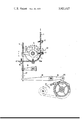
In the drawing, there is shown endless filling thread conveyor chain 1 trained about sprocket 3 for continuous movement in the direction of arrow A. Chain 1 has mounted thereon a plurality of thread clamps 2, the clamps being spaced regularly along the chain and being sequentially moved into a position 12 for receiving a respective one of the filling threads from the yarn cones of a filling thread supply chain (not shown).
As is conventional the clamp 2 comprises a movable clamp head 4 mounted on stem 5 and cooperating with anvil 7, a helical spring 6 mounted on the stem between anvil 7 and cam follower l1 biasing the head 4 against the anvil 7 to keep the clamp normally closed. A cam disc 9 is keyed to the axle 8 of sprocket 3 to be rotated therewith and has a cam 10 for opening a clamp in the thread take-up position 12 when the cam 10 engages cam follower 11 on the clamp stem, thus moving the clamp head against the bias of spring 6. Thus, the clamp is moved from the closed to the open position. The clamp receives the filling thread in the open position at take-up point 12 and is taken along by the clamp as it closes under the pressure of spring 6 as the chain 1 moves on from position 12. Thus, the filling thread is conveyed to the knitting station where the fabric is being knitted so that the filling thread may be laid therein.
When it is not desired to lay a filling thread, the cam disc 9 is displaced so that the cam assumes position 10a out of alignment with thread take-up point 12. In this displaced position, the cam will not open the clamp at the thread take-up point when the thread is delivered from theyarn cone but, according to the displacement angle of cam position 10a, at a later point when the yarn cone has passed by this point so that no thread will be supplied to thread conveyor chain for laying in the fabric.
The control means for operating the cam means 9, 10 comprises lever arm 13 fixed to cam disc 9 and biased 'in one direction by return spring 14 tending to move the disc clockwise. The lever arm is also connected to a push rod 15 which is pivoted to one-armed lever 16. One end of a tension member 17, which is illustrated by a cable line, is connected to the push rod while the other end thereof is connected to one arm of twoarmed lever 18 whose other arm carries follower roller 20 engaged by the chain of pattern mechanism 21'.
Thus, when the pattern mechanism causes the clamp operating cam to be in position 10a, no filling thread will be supplied to the machine, thus changing the pattern of the knit fabric at will in accordance with the chosen pattern without interruption of the knitting operation.
I claim:
1. An apparatus for conveying filling threads to a warp knitting machine, comprising 1. a filling thread conveyor chain,
2. a plurality of thread clamps spacedly mounted along the chain,
a. each of the thread clamps being sequentially moved into a position for receiving a respective one of the filling threads,
3. a cam means mounted at said position for moving a respective one of the thread clamps upon operation of the cam means between a clamp opening and clamp closing position,
4. control means for operating the cam means, and
5. a pattern mechanism,
a. the control means being operatively associated with the cam means and the pattern mechanism for operating the cam means in response to the pattern mechanism.
2. The apparatus of claim 1, wherein the cam means is a cam disc having a cam for closing the clamp upon rotation of the cam disc.
3. The apparatus of claim 1, wherein the control means comprises a return 'spring tending to move the cam means in one direction and a tension member tending to move the cam means in a direction opposite to the one direction, the tension member being responsive to the pattern mechanism.
Claims (7)
1. An apparatus for conveying filling threads to a warp knitting machine, comprising 1. a filling thread conveyor chain, 2. a plurality of thread clamps spacedly mounted along the chain, a. each of the thread clamps being sequentially moved into a position for receiving a respective one of the filling threads, 3. a cam means mounted at said position for moving a respective one of the thread clamps upon operation of the cam means between a clamp opening and clamp closing position, 4. control means for operating the cam means, and 5. a pattern mechanism, a. the control means being operatively associated with the cam means and the pattern mechanism for operating the cam means in response to the pattern mechanism.
2. a plurality of thread clamps spacedly mounted along the chain, a. each of the thread clamps being sequentially moved into a position for receiving a respective one of the filling threads,
2. The apparatus of claim 1, wherein the cam means is a cam disc having a cam for closing the clamp upon rotation of the cam disc.
3. The apparatus of claim 1, wherein the control means comprises a return spring tending to move the cam means in one direction and a tension member tending to move the cam means in a direction opposite to the one direction, the tension member being responsive to the pattern mechanism.
3. a cam means mounted at said position for moving a respective one of the thread clamps upon operation of the cam means between a clamp opening and clamp closing position,
4. control means for operating the cam means, and
5. a pattern mechanism, a. the control means being operatively associated with the cam means and the pattern mechanism for operating the cam means in response to the pattern mechanism.
Applications Claiming Priority (1)
| Application Number | Priority Date | Filing Date | Title |
|---|---|---|---|
| DE2114699A DE2114699C3 (en) | 1971-03-26 | 1971-03-26 | Warp knitting machine with long weft device |
Publications (1)
| Publication Number | Publication Date |
|---|---|
| US3921417A true US3921417A (en) | 1975-11-25 |
Family
ID=5802846
Family Applications (1)
| Application Number | Title | Priority Date | Filing Date |
|---|---|---|---|
| US236264A Expired - Lifetime US3921417A (en) | 1971-03-26 | 1972-03-20 | Apparatus for conveying filling threads to a warp knitting machine |
Country Status (5)
| Country | Link |
|---|---|
| US (1) | US3921417A (en) |
| JP (1) | JPS5122536B1 (en) |
| DD (1) | DD96274A5 (en) |
| DE (1) | DE2114699C3 (en) |
| GB (1) | GB1349497A (en) |
Citations (9)
| Publication number | Priority date | Publication date | Assignee | Title |
|---|---|---|---|---|
| US2005951A (en) * | 1932-06-25 | 1935-06-25 | Morton James | Manufacture of fabrics |
| US3145549A (en) * | 1958-08-06 | 1964-08-25 | Siccardi Francesco | Apparatus for producing a knitted fabric having an inlay of weft threads |
| US3364701A (en) * | 1966-02-25 | 1968-01-23 | Stevens & Co Inc J P | Apparatus for feeding filling threads to a warp knitting machine |
| US3410113A (en) * | 1966-04-06 | 1968-11-12 | Rudolph G. Bassist | Knitting machine having a chopper bar controlling mechanism |
| US3446038A (en) * | 1967-06-16 | 1969-05-27 | Toshiaki Inui | Weft inserting method and apparatus |
| US3603117A (en) * | 1968-04-22 | 1971-09-07 | Elitex Zavody Textilniho | Warp-knitted pile fabric |
| US3606769A (en) * | 1969-06-16 | 1971-09-21 | Stevens & Co Inc J P | Continuous weft feed for warp knitting machines |
| US3636731A (en) * | 1970-08-04 | 1972-01-25 | Robert F Jones | Tension-relaxing device for feeding filling threads to a warp knitting machine |
| US3705503A (en) * | 1970-07-02 | 1972-12-12 | Elitex Zavody Textilniho | Apparatus for forming a system of weft threads for further processing in textile machines |
-
1971
- 1971-03-26 DE DE2114699A patent/DE2114699C3/en not_active Expired
-
1972
- 1972-03-16 GB GB1245272A patent/GB1349497A/en not_active Expired
- 1972-03-20 US US236264A patent/US3921417A/en not_active Expired - Lifetime
- 1972-03-22 DD DD161719A patent/DD96274A5/xx unknown
- 1972-03-27 JP JP47030652A patent/JPS5122536B1/ja active Pending
Patent Citations (9)
| Publication number | Priority date | Publication date | Assignee | Title |
|---|---|---|---|---|
| US2005951A (en) * | 1932-06-25 | 1935-06-25 | Morton James | Manufacture of fabrics |
| US3145549A (en) * | 1958-08-06 | 1964-08-25 | Siccardi Francesco | Apparatus for producing a knitted fabric having an inlay of weft threads |
| US3364701A (en) * | 1966-02-25 | 1968-01-23 | Stevens & Co Inc J P | Apparatus for feeding filling threads to a warp knitting machine |
| US3410113A (en) * | 1966-04-06 | 1968-11-12 | Rudolph G. Bassist | Knitting machine having a chopper bar controlling mechanism |
| US3446038A (en) * | 1967-06-16 | 1969-05-27 | Toshiaki Inui | Weft inserting method and apparatus |
| US3603117A (en) * | 1968-04-22 | 1971-09-07 | Elitex Zavody Textilniho | Warp-knitted pile fabric |
| US3606769A (en) * | 1969-06-16 | 1971-09-21 | Stevens & Co Inc J P | Continuous weft feed for warp knitting machines |
| US3705503A (en) * | 1970-07-02 | 1972-12-12 | Elitex Zavody Textilniho | Apparatus for forming a system of weft threads for further processing in textile machines |
| US3636731A (en) * | 1970-08-04 | 1972-01-25 | Robert F Jones | Tension-relaxing device for feeding filling threads to a warp knitting machine |
Also Published As
| Publication number | Publication date |
|---|---|
| GB1349497A (en) | 1974-04-03 |
| JPS5122536B1 (en) | 1976-07-10 |
| DE2114699C3 (en) | 1973-10-04 |
| DE2114699B2 (en) | 1973-03-15 |
| DE2114699A1 (en) | 1972-10-19 |
| DD96274A5 (en) | 1973-03-12 |
Similar Documents
| Publication | Publication Date | Title |
|---|---|---|
| US3756043A (en) | Flat warp knitting machines | |
| GB1479368A (en) | Machine and method for producing knit-goods with a pile or loop-pile surface | |
| US3921417A (en) | Apparatus for conveying filling threads to a warp knitting machine | |
| US3680332A (en) | Apparatus for feeding filling threads to a warp knitting machine | |
| US4442684A (en) | Control of weft thread insertion | |
| US3797278A (en) | Warp knitting machine | |
| US3606769A (en) | Continuous weft feed for warp knitting machines | |
| US2309026A (en) | Thread tensioning mechanism for textile fabricating machines | |
| US3514978A (en) | Magazine bar for transferring knitted fabric | |
| US2912840A (en) | Yarn carrier mechanism for flat knitting machines | |
| US3350901A (en) | Guide bar lapping mechanism for warp knitting machines | |
| US3375681A (en) | Flat bed knitting machines and method of knitting | |
| GB723091A (en) | Improvements in or relating to warp knitting machines | |
| US2034869A (en) | Knitting machine | |
| US3511284A (en) | Filling selective device for shuttleless looms | |
| US3390551A (en) | Selection device of carrier rods for knitting machines | |
| US3606771A (en) | Yarn feeder control mechanism for circular knitting machines | |
| US2400628A (en) | Yarn control | |
| US1008752A (en) | Striping and embroidering mechanism for knitting-machines. | |
| ES426532A1 (en) | Devices for laying layers of weft threads | |
| US1228483A (en) | Knitting-machine. | |
| US2348598A (en) | Mechanism for supplying yarn and thread to the needles of knitting machines | |
| GB1299638A (en) | Improvements in or relating to flat warp knitting machines, particularly stitch-bonding machines | |
| US3862552A (en) | Weft arrangement for wrap knitting machines | |
| US2202521A (en) | Yarn feeding mechanism for straight knitting machines |