US3908321A - Installation of conduits in precast concrete housing - Google Patents
Installation of conduits in precast concrete housing Download PDFInfo
- Publication number
- US3908321A US3908321A US375842A US37584273A US3908321A US 3908321 A US3908321 A US 3908321A US 375842 A US375842 A US 375842A US 37584273 A US37584273 A US 37584273A US 3908321 A US3908321 A US 3908321A
- Authority
- US
- United States
- Prior art keywords
- interior wall
- floor slab
- wall
- electrical
- floor structure
- Prior art date
- Legal status (The legal status is an assumption and is not a legal conclusion. Google has not performed a legal analysis and makes no representation as to the accuracy of the status listed.)
- Expired - Lifetime
Links
Images


Classifications
-
- E—FIXED CONSTRUCTIONS
- E04—BUILDING
- E04B—GENERAL BUILDING CONSTRUCTIONS; WALLS, e.g. PARTITIONS; ROOFS; FLOORS; CEILINGS; INSULATION OR OTHER PROTECTION OF BUILDINGS
- E04B1/00—Constructions in general; Structures which are not restricted either to walls, e.g. partitions, or floors or ceilings or roofs
- E04B1/348—Structures composed of units comprising at least considerable parts of two sides of a room, e.g. box-like or cell-like units closed or in skeleton form
- E04B1/34815—Elements not integrated in a skeleton
- E04B1/34823—Elements not integrated in a skeleton the supporting structure consisting of concrete
Definitions
- Each concrete building unit includes a floor slab. upright loadbearing exterior walls joined with the perimeter of the floor slab. and a sloping roof cast integrally with the tops of the exterior walls. The building units are arranged so that the roof of each unit slopes upwardly toward the other unit. with the elevated ends of the roofs meeting to form an inverted Vshapcd pitch roof. Interior walls are cast integrally with the exterior walls and the roof to divide the building units into separate rooms.
- the bottoms of the interior walls are spaced above the floor slab so that no loads are transmitted to the floor slab by the walls. and plumbing and wiring are run through the space between the bottom of the interior walls and the floor slab.
- a reinforcing cage formed from welded wire mesh is embedded in each exterior wall.
- This invention relates to housing, and more particularly to precast concrete modular dwelling units.
- Concrete modular houses also have been produced to satisfy the need for prefabricated housing.
- modular concrete houses are assembled from concrete modular units, or segments, and separate interior and exterior wall panels. The modular units and wall panels are transported to the building site where a substantial amount of construction must be done to erect them into a completed house.
- This invention provides a precast concrete building unit which may be joined with one or more similar precast concrete building units to form a concrete modular house.
- the building units may be precast in a casting yard and transported to the construction site where they are placed on a foundation and connected together to form a completed concrete dwelling house.
- each building unit includes a floor slab, exterior walls joined with the floor slab, a roof cast with the exterior walls, and interior walls cast with the roof and the insides of the exterior walls. Finishing procedures such as installation of doors, windows, electrical lines, plumbing, and painting are performed at the casting site. Thus, a minimum amount of construction at the building site is required to connect the buildings together. This work consists primarily of setting the modules on the foundation, connecting them together, and making the necessary utility connections.
- the roof, the exterior walls, and the interior walls are cast integrally with an appropriate pitch on the roof sothat when 'two of the modular units are joined together, the completed house has a pitch roof.
- the interior walls preferably are cast to be spaced above the upper surface of the floor slab when the exterior walls are joined with the floor slab. Thus, no load is transmitted to the floor slab by the interior walls.
- FIG. 1 is a perspective view showing a precast concrete modular building unit
- FIG. 2 is a fragmentary plan elevation view showing the floor, slabs of a pair of side-by-side modular building units which are connected together to form a house;
- FIG. 3 is an elevation view showing the end of a pair of modular building units connected together to form a house, and an elevation view of the floor slabs of the building units taken on line 3-3 of FIG. 2;
- FIG. 4 is an enlarged fragmentary elevation view of the reinforcing means shown within the circle 4 of FIG.
- FIG. 5 is a fragmentary elevation view taken on line 5-5 of FIG. 2 showing the reinforcing means for the transverse beams of the floor slab;
- FIG. 6 is a plan elevation view showing the floor plan of a completed house
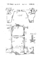
- FIG. 7 is a sectional elevation view taken on line 77 of FIG. 6 showing an interior wall of the modular building unit with an electrical outlet'and an electrical conduit cast in place in the wall;
- FIG. 8 is a sectional elevation view taken on line 8-8 of FIG. 6 showing an interior wall of the modular building unit with a gas line between the bottom of the wall and the floor slab;
- FIG. 9 is a sectional elevation view taken on line 9-9 of FIG. 6 showing the means for reinforcing an exterior wall of the modular building unit;
- FIG. 10 is a sectional elevation view showing an alternate form of the reinforcing means shown in FIG. 9;
- FIG. 11 is a sectional elevation view showing a further alternate form of the reinforcing means shown in FIG. 9;
- FIG. 12 is an enlarged elevation view of the means for connecting the roofs shown within the circle 12 of FIG. 3;
- FIG. 13 is a fragmentary schematic elevation view showing means for securing an exterior wall to the floor slab
- FIG. 14 is a fragmentary schematic elevation view showing means for securing a shear panel between two modular building units
- FIG. 15 is an enlarged fragmentary elevation view taken on line 1515 of FIG. 14;
- FIG. 16 is an elevation view taken on line 16-16 of FIG. 14;
- FIG. 17 is a sectional elevation view showing means for casting the insulation in the roof of the modular unit
- FIG. 18 is an elevation view showing a reinforcing arch cast in the concrete surrounding an opening in an exterior wall of the modular unit;
- FIG. 19 is a sectional elevation view taken on line 19-19 of FIG. 18;
- FIG. 20 is a fragmentary elevation view showing two alternate modular building units secured together without a shear panel
- FIG. 21 is a plan elevation view taken on line 21-2l of FIG. 20.
- FIG. 22 is an enlarged elevation view of the means for connecting the roofs shown within the circle 22 of FIG. 20.
- a precast concrete building unit includes a pair of parallel upright exterior side walls 12, a long exterior end wall 14 (shown in FIG. 3) cast integrally at its ends with a respective end of each side wall, a long exterior center wall 16 cast integrally at its ends with the other ends of exterior side Walls 12, and a roof 18 which is cast integrally with the tops of exterior walls, 12, 14, and 16.
- the roof slopes upwardly toward center wall 16, thereby making the height of center wall 16 greater than that of end wall 14.
- the exterior walls of building unit 10 are joined with the perimeter of a rectangular precast concrete floor slab 19 to form a modular concrete halfdwelling unit 20 which forms half of a completed house 22 shown best in plan view in FIGS. 2 and 6, and in end view in FIG. 3.
- the means for joining building unit 10 with floor slab 19 will be described in detail below.
- Window openings such as an opening 24 in side wall 12, may be cast in either of side walls 16 or in end wall 14.
- One or more doorway openings such as openings 26, 28, and which are cast in center wall 16, may be cast in end wall 14 and either of the side walls, as well asthe center wall.
- Openings 28 and 30, which are spaced relatively close to each other, are separated by an interior wall 32 which divides modular unit 20 into separate rooms.
- a second interior wall 34 adjacent door opening 26 also divides the unit into separate rooms.
- each room in dwelling unit 20 has direct access to the mating other half of house 22 either through door openings 26, 28, or 30.
- Building unit 10 and floor slab 19 are cast separately in a casting yard.
- Horizontal lifting holes 35 are cast in the long sides of floor slab 19 to receive lifting pins (not shown).
- a spreader bar (not shown) strapped to the lifting pins hoists the floor slab.
- the elevated end portion of roof 18 above center wall 16 is cast in an outwardly and upwardly projecting overhang 36.
- a downwardly and outwardly projecting overhang 38 is cast with the lower edge of roof 18 above end wall 14.
- Longitudinally spaced apart vertical lifting holes 40 are cast in each overhang 36 and 38 to permit the passage of lifting devices, such as cables (not shown). from a gantry crane (not shown) positioned over building unit 10.
- a lifting arm (not shown) secured to the end of each cable bears against the undersurface of each overhang portion of the roof to per-.
- Overhang 38 has a flat, horizontal undersurface 42 to permit the wall of the casting form (not shown) to be moved horizontally outwardly from end wall 14 without having its movement interrupted by the overhang portion of the roof.
- Floor slab 19 is cast as a unit by constructing a rigid reinforcing steel cage in a mold (not shown) and pour ing concrete into the mold to form the floor slab and the beams which project downwardly from the undersurface of the floor slab.
- the configuration of the pre ferred reinforcing steel cage is shown best in FIGS. 4 and 5.
- the horizontal portion of floor slab 19 is reinforced by a horizontal wire mesh panel 54 (shown schematically in FIGS. 4 and 5) made of pieces of six-gauge wire which are welded together to form a reinforcing grid.
- the wire mesh panel covers substantially the entire horizontal area of the floor slab.
- Spaced apart" downwardly opening notches 102 are cast in the bottom surfaces of the outer transverse beams 46 and large transverse beams 50 and 52, thereby forming spaced apart downwardly projecting teeth or shear keys 104 in each beam.
- the shear keys are embedded in the foundation grout to form an undulating interface between the floor slab beams and the foundation, which aids in pre'venting movement of the housing floorslab 19 relative to the foundation.
- the shear keys also prevent movement of the floor slab relative to a floor slab of an adjacent modular half-dwelling unit 20 which makes up the other half of the completed house 22.
- Foundation 106 preferably comprises a separate elongated trench 107 (see FIG.
- levelling pads 110 (shown in dotted lines" in FIG. 4) are placed at spaced apart locations in trenches 107. Longitudinal beams 44 rest on the pads when the floor slab is placed on the foundation, with a sufficient number of the pads being used at each location to level the floor slab.
- a separate pair of parallel elongated reinforcing bars 109 which extend the width of the floor slab, are embedded in foundation grout 106 below each outer transverse beam 46 and below each of the large transverse beams 50-and 52.
- Reinforcing bars 109 preferably are number six steel rods.
- a separate vertically extending anchor 111(shown in FIG. 3) embedded in each outer transverse beam 46 extends into the foundation grout between the respective pair of reinforcing bars 109 below it.
- Each anchor 111 is rigidly secured, such as by tying or welding, to each of the reinforcing bars 109 to provide additional resistance to the floor slab 19 and foundation 106 from being pulled apart.
- a separate identical anchor 11] embedded in each of the large transverse beams 50 and 52 extends into the foundation grout between the pair of reinforcing bars 109 below it.
- Each of these anchors is rigidly secured by suitable means to a corresponding one of the reinforcing bars 50,52.
- the completed modular house 22 is formed by placing two modular halfdwelling units 20 parallel to each other on foundation 106, with the cantilevered overhang 36 of one half closely spaced from that of the other half so the two roofs 18 cooperate to form a conventional pitch roof.
- an elongated open-ended corridor 112 is formed between the parallel center walls 16.
- Each half-dwelling unit 20 is placed on its respective floor slab so that the bottom of center wall 16 rests on the horizontal ridge 68 of the floor slab.
- the bottom of each end wall 14 rests on an elongated outwardly projecting horizontal outer ridge 114 cast integrally with the edge on the long side of the floor slab 19 opposite ridge 68.
- the bottom of each side wall 12 rests on an elongated outwardly projecting horizontal ridge 116 (see FIG. 5) cast integrally with the edge on each short side of the floor slab.
- FIG. 4 shows an example of one means for securing the bottom portions of exterior walls 14 and 16 to the floor slab.
- the bottom portion of end wall 14 is set in a layer of bonding material 1 17, such as grout, on outer ridge 114 of the floor slab.
- the bottom of center wall 116 is set in an identical layer of bonding material 117 on bearing surface 68 of ridge 64.
- the space between the inner edge of each wall and the floor slab is filled with a layer of epoxy grout 118 to complete bonding of the walls to the floor slab.
- FIG. 5 shows an identical means for securing the bottom portion of each side wall 12 to the floor slab.
- FIG. 13 shows means which are presently preferred for securing the bottom portions of the exterior walls of the floor slab.
- elongated, spaced apart, horizontal anchor bars 120 preferably number six steel rods, are placed between the inside of exterior side wall 12 and the vertical outer edge of floor slab 19.
- the anchor bars preferably are spaced 32 inches apart along the floor slab.
- An angular L-shaped weld plate 122 which runs the length of the floor slab, is exposed at the vertical edge of the floor slab adjacent to anchor bars 120.
- the angular weld plate 121 is held in place by spaced apart anchor rods 122 which are embedded in the floor slab.
- Spaced apart flat weld plates 123 are exposed along the inside of exterior side wall 12 adjacent to each anchor bar 120.
- Weld plates 123 are held in place by respective inwardly extending anchor rods 124 which are embedded in exterior side wall 12. It is preferred to place an anchor bar 120 and a cooperating weld plate 123 at least 8 inches from the corners of the floor slab and the corners of any interior walls.
- One side of each anchor bar 120 is welded to weld plate 121, and the other side of each anchor bar is welded to a respective weld plate 123 to rigidly fasten exterior end wall 12 to the floor slab.
- Access for welding is obtained by blocking out Spaced part notches 125 in the edge of the floor slab adjacent to each anchor bar 120. After welding is completed the blocked out notches are filled with grout 126.
- center wall 16 On the other side of the floor slab identical means are used to secure center wall 16 to the floor slab.
- Spaced apart anchor bars 127 are placed between the inside of center wall 16 and the floor slab, with a continuous angled weld plate 128 embedded in the floor slab on one side of the anchor bars, and respective spaced apart flat weld plates 129 embedded in center wall 16 on the other side of each anchor bar.
- Grout 130 is poured in the respective spaces between exterior walls 12 and 16 and the floor slab after welding is finished to complete the bonding of the walls to the floor slab.
- Means similar to that shown in FIG. 13 preferably are used to secure exterior side walls 14 to the floor slab.
- FIG. 12 shows the preferred means for securing together the adjacent ends of overhang portions 36 of roofs 18.
- a separate elongated right-angle weld plate 131 is exposed at the lower corner of each overhang 36, so the two weld plates face each other.
- Each weld plate 131 extends the length of the roof and is held in place by spaced apart elongated anchor rods 132 which are rigidly secured to the inside of their respective weld plates and embedded in concrete overhang 36.
- Anchor rods 132 preferably are spaced 18 inches apart along the length of the roof.
- An elongated anchor bar 134 which runs the length of the roof, rests between weld plates 131. Each weld plate 131 is welded to a respective side of anchor bar 134 to rigidly secure the overhang portions of the roofs together.
- Grout 136 is poured in the space between the ends of overhang portions 36 above anchor bar 134 to complete bonding of the roofs.
- an elongated concrete corridor floor slab 151 extends substantially the entire length of the house to provide the floor for the corridor or hallway 112 between the two half-dwelling units.
- the horizontal upper surface of corridor floor slab 151 is in the same plane as the upper surface of each floor slab 19.
- a pair of parallel, laterally spaced apart, elongated marginal ridges 152 project downwardly from the underside of the corridor floor slab along the outer edges of the slab.
- Each marginal ridge runs the length of the corridor floor slab, with a separate elongated reinforcing bar 153 being embedded substantially in the center of each ridge.
- Each reinforcing bar 153 runs the length of the corridor floor slab and preferably is a number four steel rod.
- the corridor floor slab is mounted between the modular half-dwelling units so each marginal ridge 152 rests on the outwardly projecting horizontal upper surface 68 of a respective one of the ridges 64 which extend the length of the corridor.
- each marginal ridge 152 is set in grout bed 117 which also secures center wall 16 to the floor slab.
- Spaced apart leveling pads may be set below marginal ridges 152 to shim the corridor floor slab.
- Grout 1 17 also fills a portion of the space between the outer edge of the corridor floor slab and the adjacent outer edge of the center wall 16. A portion of the space above grout 117 is filled with an epoxy grout 154 to complete bonding of the corridor floor slab to the center wall.
- the corridor floor slab may be welded to each center wall in a manner akin to that shown for the exterior walls in FIG. 13.
- each shear panel 158 preferably is a precast concrete slab which is shaped to fit into the opening at each end of the corridor in front of corridor floor slab 151.
- Each edge of the shear panel is joined with the edge of an adjacent center wall 16 by welding it at a plurality of vertically spaced apart points shown schematically at 159 in FIG. 14.
- FIG. 15 The preferred means for joining the shear panel to the center wall is shown in FIG. 15 in which vertically spaced apart flat weld plates l60'are mounted at the edge of each exterior center wall 16.
- Each weld plate 160 preferably is held in place by a pair of vertically spaced apart anchor rods 162 embedded in center wall 16.
- the vertical spacing between adjacent weld plates 160 preferably is 32 inches.
- a separate continuous vertical weld plate 164 is mounted at each vertical edge of shear panel 158.
- Each angular weld plate is held in place by spaced apart anchor rods 166 embedded in the shear panel.
- Spaced apart, vertical elongated anchor bars 170 are placed between each weld plate 160 and angular weld plate 162.
- the weld plates are welded to opposite sides of anchor bars 170 to rigidly secure each edge of shear panel 158 to a respective center wall 16. Access for welding is obtained by blocked out notches 171 formed in each edge of the shear panel adjacent to anchor bars 170. After welding is completed the notches are filled with grout 172.
- each shear panel 158 are secured to the outer edges of beams 44 of the floor slab at points shown schematically at 173 in FIG. 14.
- Connecting means identical to that shown at 159 in FIG. preferably are used to connect the lower portions of the shear panels to the floor slab beams.
- the lower edge of each shear panel 158 is embedded in foundation grout 106 as shown best in FIG. 16.
- Connecting means identical to that shown in FIG. 15 also are preferably used to secure the upper edge of each shear panel to overhang portions 36 of roofs 18. (These connecting means are shown schematically at 174 in FIG. 14).
- each shear panel is rigidly secured around its perimeter to center walls 16, the longitudinal beams 44 of the floor slab, the foundation 106, and the roof overhang 36 to provide the equivalent of at least an 8 foot beam which provides substantial rigidity and strength for each end of the completed house.
- the space 176 between the edge of each shear panel and the adjacent center walls 16 and roof overhang 36 is filled with grout to complete the bonding of the shear panel to the modular half-dwelling units.
- each half-dwelling unit has a central core of insulation which makes these walls thicker than exterior center walls 16.
- insulated side walls 12 and end walls 14 are about 5 inches thick, and the center walls are about 3 inches thick.
- Center walls 16 are reinforced by a vertically disposed welded wire mesh panel (not shown) similar to that used to reinforce floor slab 19.
- FIG. 9 shows a detailed view of the insulation and reinforcing for side wall 12, which includes a reinforcing cage formed from laterally spaced apart welded wire mesh panels 184 which are inserted in the form (not shown) used to cast the side wall.
- Each welded wire mesh panel 184 is formed from longitudinally spaced apart vertically extending wire reinforcing rods 186 welded to intersecting vertically spaced apart horizontal wire reinforcing rods 187 (shown schematically in FIG. 9) to form a reinforcing grid.
- each modular half-dwelling unit Preferably, the top of each interior wall is cast integrally with the underside of roof 18, with at least one side of the interior wall being cast integrally with the inside of one of the exterior walls.
- an interior wall 206a extends approximately half the width of the modular unit.
- the end of wall 206a is cast integrally with end wall 14 and at its top is cast integrally with roof 18.
- a short interior wall 206b in the same plane as interior wall 206a is integral with center wall 16 at its end and with roof 18 at its top.
- a third interior wall 206C extends the entire width of the modular unit.
- wall 2066 The ends of wall 2066 are cast integrally with end wall 14 and center wall 16, and the top of wall 2060 is cast integrally with roof 18.
- an interior wall 206d extends about threefourths of the width of the unit.
- One end of wall 206d is integral with end wall 14, and the top of wall 206d is integral with roof 18.
- each interior wall 206 is cast so each wall has a lower surface 208 which is spaced a short distance above the upper surface of floor slab 19 when the modular half-dwelling units are joined with the floor slab.
- the interior walls and roof transmit no load to the thin portion of the floor slab under the interior walls. Instead, the interior walls are held in tension by the roof and at least one exterior wall, with all the load of the roof and the interior walls being transmitted down through the exterior walls and shear panels.
- the interior walls 206 are cast so that their bottom edges 208 are at least one inch above the upper surface of floor slab 19. As shown best in FIG. 7, this spacing permits electrical wiring such as a conventional Romex electrical cable 210 to be run under interior wall 206 and connected with a conduit 211 from a conduit box 212 providing electrical outlets 214. Electrical conduits and conduit boxes are cast in place in the interior walls and extension walls. The conduits are pre-wired prior to casting to facilitate installation of the electrical wiring. Electrical cables (not shown) strung from a main power source (not shown) are connected to the pre-wired conduits through openings 215 (see FIG. 1) which are cast in center wall 16. Preferably, a spacing of 1 inch is provided between the bottom 208 of interior wall 206 and floor slab 19 in the arrangement shown in FIG. 7.
- FIG. 8 shows another use for the spacing between the bottom of an interior wall and the floor slab.
- a larger spacing preferably 2 or 3 inches, is provided for plumbing, such as a water line or gas line 210 to be run under the interior wall.
- each interior wall is enclosed by a separate elongated strip or molding 216 extending vertically from each side of the interior wall to the floor slab.
- the molding is releasably secured to the wall and floor slab to permit access to the electrical lines or plumbing.
- the plumbing and wiring are run to the exterior of the house through openings (not shown) formed in either the floors or walls by blocks (not shown) when the modular dwelling units are cast.
- the blocks are removable from the modular units and the openings are covered by suitable means after the plumbing or wiring are run through them.
- the modular half-dwelling units 20 are particularly suitable for being produced and outfitted in completed form in an assembly-line fashion in a casting yard.
- Floor slab l9 and the walls of building unit 10 are cast separately, with building unit 10 being lifted onto the floor slab at the casting yard after the concrete has set and the mold forms are removed.
- the exterior walls of the building unit are joined with the perimeter of the floor slab to form the outer shell of the modular halfdwelling unit 20.
- Shear panels 58 and corridor floor slab 51 are cast as separate units in the casting yard.
- the interior of the modular half-dwelling unit also is finished at the casting site. Plumbing and electrical wiring is run under interior walls 206 of each modular unit, and molding strips 216 are fastened to the bottom of each interior wall to finish the interior walls. Insulation panels 200 are mounted against center walls 16 if the completed house is to include a long unit and short unit. A ceiling (not shown) made of nonload-bearing wallboards such as gypsum wallboard is placed on mounting tracks (not shown) in the upper portion of each modular half-dwelling unit. A similar ceiling is mounted in the upper portion of corridor 112 to form an attic space. Several removable nonload-bearing vertical wall panels 242 (see FIG.
- the completed modular half-dwelling units are then transported to the building site where they are assembled to form a completed house.
- Two units are set sideby-side on foundation 106.
- the overhang portions 36 of the roof 18 are connected together, and the corridor floor slab 151 is mounted between half-dwelling units.
- Shear panels 158 are then mounted at the ends of the house to connect the half-dwelling units together.
- An air conditioning and heating unit 248 (see FIG. 6) is mounted in the upper portion of the corridor at one end of the house.
- Ducts 250 in the attic space above the ceiling in the corridor deliver air from the heating and air conditioning unit to each room in the house.
- the ducts open into each room through openings 252 (see FIG. 1) which are cast in center walls 16. Exterior trimming (not shown) is then added to the house and the house is in its completed form ready for use as a single family dwelling unit.
- a precast concrete building unit comprising the combination of a floor structure having a top surface; at least one upright cast concrete load-bearing exterior wall joined with the floor structure and extending above the top surface of the floor structure; a roof cast integrally with one or more of the exterior walls; an interior wall having an end which is cast integrally with at least one of the exterior walls and a top which is cast integrally with the roof, the interior wall having an undersurface spaced from the upper surface of the floor structure so that the interior wall does not transmit a load to the floor structure; an electrical outlet embedded in the interior wall; and an electrical conduit extending between the undersurface of the interior wall and the upper surface of the floor structure, the electrical conduit being connected to the embedded electrical outlet.
- a precast concrete building unit comprising the combination of a floor structure having an upper surface; at least one upright precast concrete load-bearing exterior wall joined with the floor structure and extending above the upper surface of the floor structure; an interior wall cast integrally with the exterior wall, the undersurface of the interior wall being spaced from the upper surface of the floor structure so that the interior wall does not transmit a load to the floor structure; an elongated strip of molding on each side of the interior wall for covering the space between the floor structure and the bottom of the interior wall to form an elongated enclosed area below the interior wall; an electrical outlet embedded in the precast interior wall; and an electrical conduit extending between the undersurface of the interior wall and the upper surface of the floor structure, the electrical conduit being connected to the embedded electrical outlet.
Abstract
A pair of precast concrete building units are joined together to form a modular concrete house. Each concrete building unit includes a floor slab, upright load-bearing exterior walls joined with the perimeter of the floor slab, and a sloping roof cast integrally with the tops of the exterior walls. The building units are arranged so that the roof of each unit slopes upwardly toward the other unit, with the elevated ends of the roofs meeting to form an inverted V-shaped pitch roof. Interior walls are cast integrally with the exterior walls and the roof to divide the building units into separate rooms. The bottoms of the interior walls are spaced above the floor slab so that no loads are transmitted to the floor slab by the walls, and plumbing and wiring are run through the space between the bottom of the interior walls and the floor slab. A reinforcing cage formed from welded wire mesh is embedded in each exterior wall.
Description
United States Patent 1191 Cox et al.
1451 Sept. 30, 1975 1 1 INSTALLATION OF CONDUITS IN PRECAST CONCRETE HOUSING 1731 Assignee: H. B. Zachry C0.. San Antonio. Tex.
[22] Filed: July 2, 1973 [21] Appl. No.: 375,842
Related US. Application Data [62] Division of Ser. No. 191.505. Oct. 21. 1971. Pat. No.
1.156.547 10/1963 Germany .52/221 Primary Emminer-Alfred C. Perham Almrncy. Agent. or FirmChristie. Parker 8: Hale {57] ABSTRACT A pair of precast concrete building units are joined together to form a modular concrete house. Each concrete building unit includes a floor slab. upright loadbearing exterior walls joined with the perimeter of the floor slab. and a sloping roof cast integrally with the tops of the exterior walls. The building units are arranged so that the roof of each unit slopes upwardly toward the other unit. with the elevated ends of the roofs meeting to form an inverted Vshapcd pitch roof. Interior walls are cast integrally with the exterior walls and the roof to divide the building units into separate rooms. The bottoms of the interior walls are spaced above the floor slab so that no loads are transmitted to the floor slab by the walls. and plumbing and wiring are run through the space between the bottom of the interior walls and the floor slab. A reinforcing cage formed from welded wire mesh is embedded in each exterior wall.
Ill-Ill US. Patent Sept. 30,1975 Sheet10f9 3,908,321
Sheet 2 of 9 46 I II iIiJi l I I |l| I I l U.S. Patent Sept. 30,1975
U.S. Patent Sept. 30,1975 Sheet 3 of9 3,908,321
US. Patent Sept. 30,1975 Sheet "4 of9 3,908,321
lakl I.
x \wsxckw Baa a US. Patent Sept. 39,1975 Sheet5 0f9 3,908,321
US. Patent Sept. 30,1975 Sheet6 0'59 3,908,321
US. am-
Se t. 30,1975 sheet 7 of 9 3,908,321
US. Patent Sept. 30,1975 Sheet 8 of9 3,908,321
US. Patent Sept.30,1975 Sheet9of9 3,908,321
INSTALLATION OF CONDUITS IN PRECAST CONCRETE HOUSING This is a division of application Ser'. No. 191,505, filed Oct. 21, 1971 now U.S. Pat. No. 3,772,835.
BACKGROUND OF THE INVENTION This invention relates to housing, and more particularly to precast concrete modular dwelling units.
The recent housing shortage and increase in construction costs has stimulated the development of prefabricated modular housing. There is a need especially among low-income families for a durable high quality house that can be mass produced at a lower cost than conventionally built houses. 7
Most modular housing is in the form of wood frame houses made from prefabricated building wall panels, frames, and trusses. A major disadvantage of this type of housing is that the wall panels, frames, and trussesmust be constructed with extreme precision on relatively expensive framing machines. The prefabricated wall panels, frames, and trusses then are transported to the building site where substantial additional costs are incurred in erecting them into houses. I
Concrete modular houses also have been produced to satisfy the need for prefabricated housing. Generally, modular concrete houses are assembled from concrete modular units, or segments, and separate interior and exterior wall panels. The modular units and wall panels are transported to the building site where a substantial amount of construction must be done to erect them into a completed house.
SUMMARY OF THE INVENTION This invention provides a precast concrete building unit which may be joined with one or more similar precast concrete building units to form a concrete modular house. The building units may be precast in a casting yard and transported to the construction site where they are placed on a foundation and connected together to form a completed concrete dwelling house.
In its preferred form, each building unit includes a floor slab, exterior walls joined with the floor slab, a roof cast with the exterior walls, and interior walls cast with the roof and the insides of the exterior walls. Finishing procedures such as installation of doors, windows, electrical lines, plumbing, and painting are performed at the casting site. Thus, a minimum amount of construction at the building site is required to connect the buildings together. This work consists primarily of setting the modules on the foundation, connecting them together, and making the necessary utility connections.
In a preferred form of the modular building unit, the roof, the exterior walls, and the interior walls are cast integrally with an appropriate pitch on the roof sothat when 'two of the modular units are joined together, the completed house has a pitch roof. The interior walls preferably are cast to be spaced above the upper surface of the floor slab when the exterior walls are joined with the floor slab. Thus, no load is transmitted to the floor slab by the interior walls. An elongated strip of molding on each side of each interior wall'covers the space between the floor slab and the bottom of the inte-' rior wall to form an enclosed area for electrical cables, plumbing lines, and the like. i v
BRIEF DESCRIPTION THE DRAWINGS FIG. 1 is a perspective view showing a precast concrete modular building unit;
FIG. 2 is a fragmentary plan elevation view showing the floor, slabs of a pair of side-by-side modular building units which are connected together to form a house;
FIG. 3 is an elevation view showing the end of a pair of modular building units connected together to form a house, and an elevation view of the floor slabs of the building units taken on line 3-3 of FIG. 2;
FIG. 4 is an enlarged fragmentary elevation view of the reinforcing means shown within the circle 4 of FIG.
FIG. 5 is a fragmentary elevation view taken on line 5-5 of FIG. 2 showing the reinforcing means for the transverse beams of the floor slab;
FIG. 6 is a plan elevation view showing the floor plan of a completed house;
FIG. 7 is a sectional elevation view taken on line 77 of FIG. 6 showing an interior wall of the modular building unit with an electrical outlet'and an electrical conduit cast in place in the wall;
FIG. 8 is a sectional elevation view taken on line 8-8 of FIG. 6 showing an interior wall of the modular building unit with a gas line between the bottom of the wall and the floor slab;
FIG. 9 is a sectional elevation view taken on line 9-9 of FIG. 6 showing the means for reinforcing an exterior wall of the modular building unit;
FIG. 10 is a sectional elevation view showing an alternate form of the reinforcing means shown in FIG. 9;
FIG. 11 is a sectional elevation view showing a further alternate form of the reinforcing means shown in FIG. 9;
FIG. 12 is an enlarged elevation view of the means for connecting the roofs shown within the circle 12 of FIG. 3;
FIG. 13 is a fragmentary schematic elevation view showing means for securing an exterior wall to the floor slab;
FIG. 14 is a fragmentary schematic elevation view showing means for securing a shear panel between two modular building units;
FIG. 15 is an enlarged fragmentary elevation view taken on line 1515 of FIG. 14;
FIG. 16 is an elevation view taken on line 16-16 of FIG. 14;
FIG. 17 is a sectional elevation view showing means for casting the insulation in the roof of the modular unit;
l FIG. 18 is an elevation view showing a reinforcing arch cast in the concrete surrounding an opening in an exterior wall of the modular unit;
FIG. 19 is a sectional elevation view taken on line 19-19 of FIG. 18;
FIG. 20 is a fragmentary elevation view showing two alternate modular building units secured together without a shear panel;
FIG. 21 is a plan elevation view taken on line 21-2l of FIG. 20; and
FIG. 22 is an enlarged elevation view of the means for connecting the roofs shown within the circle 22 of FIG. 20.
DETAILED DESCRIPTION OF THE PREFERRED EMBODIMENTS Referring to FIG. 1, a precast concrete building unit includes a pair of parallel upright exterior side walls 12, a long exterior end wall 14 (shown in FIG. 3) cast integrally at its ends with a respective end of each side wall, a long exterior center wall 16 cast integrally at its ends with the other ends of exterior side Walls 12, and a roof 18 which is cast integrally with the tops of exterior walls, 12, 14, and 16. The roof slopes upwardly toward center wall 16, thereby making the height of center wall 16 greater than that of end wall 14.
The exterior walls of building unit 10 are joined with the perimeter of a rectangular precast concrete floor slab 19 to form a modular concrete halfdwelling unit 20 which forms half of a completed house 22 shown best in plan view in FIGS. 2 and 6, and in end view in FIG. 3. The means for joining building unit 10 with floor slab 19 will be described in detail below.
Window openings, such as an opening 24 in side wall 12, may be cast in either of side walls 16 or in end wall 14. One or more doorway openings, such as openings 26, 28, and which are cast in center wall 16, may be cast in end wall 14 and either of the side walls, as well asthe center wall. Openings 28 and 30, which are spaced relatively close to each other, are separated by an interior wall 32 which divides modular unit 20 into separate rooms. A second interior wall 34 adjacent door opening 26 also divides the unit into separate rooms. Thus, each room in dwelling unit 20 has direct access to the mating other half of house 22 either through door openings 26, 28, or 30.
Building unit 10 and floor slab 19 are cast separately in a casting yard. Horizontal lifting holes 35 are cast in the long sides of floor slab 19 to receive lifting pins (not shown). A spreader bar (not shown) strapped to the lifting pins hoists the floor slab.
The elevated end portion of roof 18 above center wall 16 is cast in an outwardly and upwardly projecting overhang 36. A downwardly and outwardly projecting overhang 38 is cast with the lower edge of roof 18 above end wall 14. Longitudinally spaced apart vertical lifting holes 40 are cast in each overhang 36 and 38 to permit the passage of lifting devices, such as cables (not shown). from a gantry crane (not shown) positioned over building unit 10. A lifting arm (not shown) secured to the end of each cable bears against the undersurface of each overhang portion of the roof to per-.
mit the building unit 10 to be lifted when the cables are drawn upwardly by the gantry crane.
Spaced apart" downwardly opening notches 102 are cast in the bottom surfaces of the outer transverse beams 46 and large transverse beams 50 and 52, thereby forming spaced apart downwardly projecting teeth or shear keys 104 in each beam. When floor slab 19 is placed on a foundation 106 (shown best in FIG. 5), the shear keys are embedded in the foundation grout to form an undulating interface between the floor slab beams and the foundation, which aids in pre'venting movement of the housing floorslab 19 relative to the foundation. The shear keys also prevent movement of the floor slab relative to a floor slab of an adjacent modular half-dwelling unit 20 which makes up the other half of the completed house 22. Foundation 106 preferably comprises a separate elongated trench 107 (see FIG. 4) of pumped-in grout which forms a concrete pad below each longitudinal beam 44, and separate transverse trenches 108 of pumped-in grout forming concrete foundation pads below each outer transverse beam 46 and below each of the large transverse beams 50 and 52. Before the floor slab is placed on the foundation, levelling pads 110 (shown in dotted lines" in FIG. 4) are placed at spaced apart locations in trenches 107. Longitudinal beams 44 rest on the pads when the floor slab is placed on the foundation, with a sufficient number of the pads being used at each location to level the floor slab.
As shown best in FIG. 5, a separate pair of parallel elongated reinforcing bars 109, which extend the width of the floor slab, are embedded in foundation grout 106 below each outer transverse beam 46 and below each of the large transverse beams 50-and 52. Reinforcing bars 109 preferably are number six steel rods. A separate vertically extending anchor 111(shown in FIG. 3) embedded in each outer transverse beam 46 extends into the foundation grout between the respective pair of reinforcing bars 109 below it. Each anchor 111 is rigidly secured, such as by tying or welding, to each of the reinforcing bars 109 to provide additional resistance to the floor slab 19 and foundation 106 from being pulled apart. A separate identical anchor 11] embedded in each of the large transverse beams 50 and 52 extends into the foundation grout between the pair of reinforcing bars 109 below it. Each of these anchors is rigidly secured by suitable means to a corresponding one of the reinforcing bars 50,52. v
As shown best in FIG. 3., the completed modular house 22 is formed by placing two modular halfdwelling units 20 parallel to each other on foundation 106, with the cantilevered overhang 36 of one half closely spaced from that of the other half so the two roofs 18 cooperate to form a conventional pitch roof. When house 22 is in its assembled form, an elongated open-ended corridor 112 is formed between the parallel center walls 16. Each half-dwelling unit 20 is placed on its respective floor slab so that the bottom of center wall 16 rests on the horizontal ridge 68 of the floor slab. The bottom of each end wall 14 rests on an elongated outwardly projecting horizontal outer ridge 114 cast integrally with the edge on the long side of the floor slab 19 opposite ridge 68. The bottom of each side wall 12 rests on an elongated outwardly projecting horizontal ridge 116 (see FIG. 5) cast integrally with the edge on each short side of the floor slab.
FIG. 4 shows an example of one means for securing the bottom portions of exterior walls 14 and 16 to the floor slab. The bottom portion of end wall 14 is set in a layer of bonding material 1 17, such as grout, on outer ridge 114 of the floor slab. The bottom of center wall 116 is set in an identical layer of bonding material 117 on bearing surface 68 of ridge 64. The space between the inner edge of each wall and the floor slab is filled with a layer of epoxy grout 118 to complete bonding of the walls to the floor slab. FIG. 5 shows an identical means for securing the bottom portion of each side wall 12 to the floor slab.
FIG. 13 shows means which are presently preferred for securing the bottom portions of the exterior walls of the floor slab. In the example shown in FIG. 13, elongated, spaced apart, horizontal anchor bars 120, preferably number six steel rods, are placed between the inside of exterior side wall 12 and the vertical outer edge of floor slab 19. The anchor bars preferably are spaced 32 inches apart along the floor slab. An angular L-shaped weld plate 122, which runs the length of the floor slab, is exposed at the vertical edge of the floor slab adjacent to anchor bars 120. The angular weld plate 121 is held in place by spaced apart anchor rods 122 which are embedded in the floor slab. Spaced apart flat weld plates 123 are exposed along the inside of exterior side wall 12 adjacent to each anchor bar 120. Weld plates 123 are held in place by respective inwardly extending anchor rods 124 which are embedded in exterior side wall 12. It is preferred to place an anchor bar 120 and a cooperating weld plate 123 at least 8 inches from the corners of the floor slab and the corners of any interior walls. One side of each anchor bar 120 is welded to weld plate 121, and the other side of each anchor bar is welded to a respective weld plate 123 to rigidly fasten exterior end wall 12 to the floor slab. Access for welding is obtained by blocking out Spaced part notches 125 in the edge of the floor slab adjacent to each anchor bar 120. After welding is completed the blocked out notches are filled with grout 126.
On the other side of the floor slab identical means are used to secure center wall 16 to the floor slab. Spaced apart anchor bars 127 are placed between the inside of center wall 16 and the floor slab, with a continuous angled weld plate 128 embedded in the floor slab on one side of the anchor bars, and respective spaced apart flat weld plates 129 embedded in center wall 16 on the other side of each anchor bar.
Means similar to that shown in FIG. 13 preferably are used to secure exterior side walls 14 to the floor slab.
FIG. 12 shows the preferred means for securing together the adjacent ends of overhang portions 36 of roofs 18. A separate elongated right-angle weld plate 131 is exposed at the lower corner of each overhang 36, so the two weld plates face each other. Each weld plate 131 extends the length of the roof and is held in place by spaced apart elongated anchor rods 132 which are rigidly secured to the inside of their respective weld plates and embedded in concrete overhang 36. Anchor rods 132 preferably are spaced 18 inches apart along the length of the roof.
An elongated anchor bar 134, which runs the length of the roof, rests between weld plates 131. Each weld plate 131 is welded to a respective side of anchor bar 134 to rigidly secure the overhang portions of the roofs together. Grout 136 is poured in the space between the ends of overhang portions 36 above anchor bar 134 to complete bonding of the roofs.
Referring to FIG. 4, an elongated concrete corridor floor slab 151 extends substantially the entire length of the house to provide the floor for the corridor or hallway 112 between the two half-dwelling units. The horizontal upper surface of corridor floor slab 151 is in the same plane as the upper surface of each floor slab 19. A pair of parallel, laterally spaced apart, elongated marginal ridges 152 project downwardly from the underside of the corridor floor slab along the outer edges of the slab. Each marginal ridge runs the length of the corridor floor slab, with a separate elongated reinforcing bar 153 being embedded substantially in the center of each ridge. Each reinforcing bar 153 runs the length of the corridor floor slab and preferably is a number four steel rod. The corridor floor slab is mounted between the modular half-dwelling units so each marginal ridge 152 rests on the outwardly projecting horizontal upper surface 68 of a respective one of the ridges 64 which extend the length of the corridor.
Preferably, each marginal ridge 152 is set in grout bed 117 which also secures center wall 16 to the floor slab. Spaced apart leveling pads (not shown) may be set below marginal ridges 152 to shim the corridor floor slab. Grout 1 17 also fills a portion of the space between the outer edge of the corridor floor slab and the adjacent outer edge of the center wall 16. A portion of the space above grout 117 is filled with an epoxy grout 154 to complete bonding of the corridor floor slab to the center wall. Alternatively the corridor floor slab may be welded to each center wall in a manner akin to that shown for the exterior walls in FIG. 13.
As shown best in FIGS. 14 through 16 the halfdwelling units are rigidly interconnected by a separate upright shear panel 158 at each end of corridor 112. Each shear panel 158 preferably is a precast concrete slab which is shaped to fit into the opening at each end of the corridor in front of corridor floor slab 151. Each edge of the shear panel is joined with the edge of an adjacent center wall 16 by welding it at a plurality of vertically spaced apart points shown schematically at 159 in FIG. 14.
The preferred means for joining the shear panel to the center wall is shown in FIG. 15 in which vertically spaced apart flat weld plates l60'are mounted at the edge of each exterior center wall 16. Each weld plate 160 preferably is held in place by a pair of vertically spaced apart anchor rods 162 embedded in center wall 16. The vertical spacing between adjacent weld plates 160 preferably is 32 inches. A separate continuous vertical weld plate 164 is mounted at each vertical edge of shear panel 158. Each angular weld plate is held in place by spaced apart anchor rods 166 embedded in the shear panel. Spaced apart, vertical elongated anchor bars 170 are placed between each weld plate 160 and angular weld plate 162. The weld plates are welded to opposite sides of anchor bars 170 to rigidly secure each edge of shear panel 158 to a respective center wall 16. Access for welding is obtained by blocked out notches 171 formed in each edge of the shear panel adjacent to anchor bars 170. After welding is completed the notches are filled with grout 172.
The lower edges of each shear panel 158 are secured to the outer edges of beams 44 of the floor slab at points shown schematically at 173 in FIG. 14. Connecting means identical to that shown at 159 in FIG. preferably are used to connect the lower portions of the shear panels to the floor slab beams. The lower edge of each shear panel 158 is embedded in foundation grout 106 as shown best in FIG. 16. Connecting means identical to that shown in FIG. 15 also are preferably used to secure the upper edge of each shear panel to overhang portions 36 of roofs 18. (These connecting means are shown schematically at 174 in FIG. 14). Thus, each shear panel is rigidly secured around its perimeter to center walls 16, the longitudinal beams 44 of the floor slab, the foundation 106, and the roof overhang 36 to provide the equivalent of at least an 8 foot beam which provides substantial rigidity and strength for each end of the completed house. After the shear panels are mounted in place, the space 176 between the edge of each shear panel and the adjacent center walls 16 and roof overhang 36 is filled with grout to complete the bonding of the shear panel to the modular half-dwelling units.
As shown best in FIG. 6, when a short modular halfdwelling unit is interconnected with a long modular halfdwelling unit, the edge of one shear panel 158 is secured to the floor slab of the long modular unit in the same plane as large transverse beam 50 of floor slab l9, and the edge of the other shear panel is secured to the floor slab in the same plane as large transverse beam 52. This arrangement provides the equivalent of a continuous reinforcing beam running the entire width of the completed house at each end of the house.
As shown best in FIG. 6, the exterior side walls 12 and exterior end walls 14 of each half-dwelling unit have a central core of insulation which makes these walls thicker than exterior center walls 16. Preferably, insulated side walls 12 and end walls 14 are about 5 inches thick, and the center walls are about 3 inches thick. Center walls 16 are reinforced by a vertically disposed welded wire mesh panel (not shown) similar to that used to reinforce floor slab 19. FIG. 9 shows a detailed view of the insulation and reinforcing for side wall 12, which includes a reinforcing cage formed from laterally spaced apart welded wire mesh panels 184 which are inserted in the form (not shown) used to cast the side wall. Each welded wire mesh panel 184 is formed from longitudinally spaced apart vertically extending wire reinforcing rods 186 welded to intersecting vertically spaced apart horizontal wire reinforcing rods 187 (shown schematically in FIG. 9) to form a reinforcing grid.
Several concrete interior walls 206 are cast integrally with the interior of each modular half-dwelling unit. Preferably, the top of each interior wall is cast integrally with the underside of roof 18, with at least one side of the interior wall being cast integrally with the inside of one of the exterior walls. For example, in long modular half-dwelling unit 140 shown in FIG. 6, an interior wall 206a extends approximately half the width of the modular unit. The end of wall 206a is cast integrally with end wall 14 and at its top is cast integrally with roof 18. A short interior wall 206b in the same plane as interior wall 206a is integral with center wall 16 at its end and with roof 18 at its top. A third interior wall 206C extends the entire width of the modular unit. The ends of wall 2066 are cast integrally with end wall 14 and center wall 16, and the top of wall 2060 is cast integrally with roof 18. In short modular half-dwelling unit 138, an interior wall 206d extends about threefourths of the width of the unit. One end of wall 206d is integral with end wall 14, and the top of wall 206d is integral with roof 18.
As shown best in FIG. 3, each interior wall 206 is cast so each wall has a lower surface 208 which is spaced a short distance above the upper surface of floor slab 19 when the modular half-dwelling units are joined with the floor slab. Thus, the interior walls and roof transmit no load to the thin portion of the floor slab under the interior walls. Instead, the interior walls are held in tension by the roof and at least one exterior wall, with all the load of the roof and the interior walls being transmitted down through the exterior walls and shear panels.
Preferably, the interior walls 206 are cast so that their bottom edges 208 are at least one inch above the upper surface of floor slab 19. As shown best in FIG. 7, this spacing permits electrical wiring such as a conventional Romex electrical cable 210 to be run under interior wall 206 and connected with a conduit 211 from a conduit box 212 providing electrical outlets 214. Electrical conduits and conduit boxes are cast in place in the interior walls and extension walls. The conduits are pre-wired prior to casting to facilitate installation of the electrical wiring. Electrical cables (not shown) strung from a main power source (not shown) are connected to the pre-wired conduits through openings 215 (see FIG. 1) which are cast in center wall 16. Preferably, a spacing of 1 inch is provided between the bottom 208 of interior wall 206 and floor slab 19 in the arrangement shown in FIG. 7.
FIG. 8 shows another use for the spacing between the bottom of an interior wall and the floor slab. A larger spacing, preferably 2 or 3 inches, is provided for plumbing, such as a water line or gas line 210 to be run under the interior wall.
The space below each interior wall is enclosed by a separate elongated strip or molding 216 extending vertically from each side of the interior wall to the floor slab. The molding is releasably secured to the wall and floor slab to permit access to the electrical lines or plumbing.
The plumbing and wiring are run to the exterior of the house through openings (not shown) formed in either the floors or walls by blocks (not shown) when the modular dwelling units are cast. The blocks are removable from the modular units and the openings are covered by suitable means after the plumbing or wiring are run through them.
The modular half-dwelling units 20 are particularly suitable for being produced and outfitted in completed form in an assembly-line fashion in a casting yard. Floor slab l9 and the walls of building unit 10 are cast separately, with building unit 10 being lifted onto the floor slab at the casting yard after the concrete has set and the mold forms are removed. The exterior walls of the building unit are joined with the perimeter of the floor slab to form the outer shell of the modular halfdwelling unit 20. Shear panels 58 and corridor floor slab 51 are cast as separate units in the casting yard.
The interior of the modular half-dwelling unit also is finished at the casting site. Plumbing and electrical wiring is run under interior walls 206 of each modular unit, and molding strips 216 are fastened to the bottom of each interior wall to finish the interior walls. Insulation panels 200 are mounted against center walls 16 if the completed house is to include a long unit and short unit. A ceiling (not shown) made of nonload-bearing wallboards such as gypsum wallboard is placed on mounting tracks (not shown) in the upper portion of each modular half-dwelling unit. A similar ceiling is mounted in the upper portion of corridor 112 to form an attic space. Several removable nonload-bearing vertical wall panels 242 (see FIG. 6) are placed on mounting tracks (not shown) on the floor slab and ceiling to separate the interior of the modular unit into rooms and to provide partitioning for closets and the like. Door jambs (not shown) are constructed, exterior doors 244 and interior doors (not shown) are mounted, windows 246 are installed, and the exterior and interior of the modular unit are painted. Interior fixtures such as a bathtub and kitchen facilities also are preferably added at the casting site.
The completed modular half-dwelling units are then transported to the building site where they are assembled to form a completed house. Two units are set sideby-side on foundation 106. The overhang portions 36 of the roof 18 are connected together, and the corridor floor slab 151 is mounted between half-dwelling units. Shear panels 158 are then mounted at the ends of the house to connect the half-dwelling units together. An air conditioning and heating unit 248 (see FIG. 6) is mounted in the upper portion of the corridor at one end of the house. Ducts 250 in the attic space above the ceiling in the corridor deliver air from the heating and air conditioning unit to each room in the house. The ducts open into each room through openings 252 (see FIG. 1) which are cast in center walls 16. Exterior trimming (not shown) is then added to the house and the house is in its completed form ready for use as a single family dwelling unit.
We claim:
1. A precast concrete building unit comprising the combination of a floor structure having a top surface; at least one upright cast concrete load-bearing exterior wall joined with the floor structure and extending above the top surface of the floor structure; a roof cast integrally with one or more of the exterior walls; an interior wall having an end which is cast integrally with at least one of the exterior walls and a top which is cast integrally with the roof, the interior wall having an undersurface spaced from the upper surface of the floor structure so that the interior wall does not transmit a load to the floor structure; an electrical outlet embedded in the interior wall; and an electrical conduit extending between the undersurface of the interior wall and the upper surface of the floor structure, the electrical conduit being connected to the embedded electrical outlet.
2. The combination according to claim 1 including a prewired electrical conduit connected to the embedded electrical outlet, and in which the electrical conduit which extends under the interior wall is an electrical cable connected to the prewired electrical conduit.
3. The combination according to claim 2 in which the prewired electrical conduit is embedded in the interior wall and extends to the space below the interior wall for connection to the electrical cable.
4. The combination according to claim 1 including an elongated strip of molding on each side of the interior wall for covering the space between the structure stucture and the undersurface of the interior wall to form an enclosed area for the electrical conduit.
5. A precast concrete building unit comprising the combination of a floor structure having an upper surface; at least one upright precast concrete load-bearing exterior wall joined with the floor structure and extending above the upper surface of the floor structure; an interior wall cast integrally with the exterior wall, the undersurface of the interior wall being spaced from the upper surface of the floor structure so that the interior wall does not transmit a load to the floor structure; an elongated strip of molding on each side of the interior wall for covering the space between the floor structure and the bottom of the interior wall to form an elongated enclosed area below the interior wall; an electrical outlet embedded in the precast interior wall; and an electrical conduit extending between the undersurface of the interior wall and the upper surface of the floor structure, the electrical conduit being connected to the embedded electrical outlet.
6. The combination according to claim 5 including a prewired electrical conduit connected to the embedded electrical outlet, and in which the electrical conduit which extends under the interior wall is an electrical cable connected to the prewired electrical conduit.
7. The combination according to claim 6 in which the prewired electrical conduit is embedded in the interior wall and extends to the space below the interior wall for connection to the electrical cable.
8. The combination according to claim 5 in which the molding strips are releasably mounted along the sides of the interior wall.
UNITED STATES PATENT AND TRADEMARK OFFICE CERTIFICATE OF CORRECTION PATENTNO.: 3,908,321
DATED I September 30, 1975 |NV.ENTOR(5) 1 Elmer A.v Cox et al it is certified that error appears in the above-identified patent and that said Letters Patent are hereby corrected as shown below:
[75] Inventors: "Adrian" should read Adrain Col. 9, line 26, "roof" should read'+ roofs Col. 10, lines 18-19, "structure stucture" should read (Claim 4) floor structure Signed and Sealed this twenty-fourth D ay Of February I 976 [SEAL] Arrest:
RUTH C. MASON C. MARSHALL DANN Arresting Officer Commissioner uj'larents and Trademarks
Claims (8)
1. A precast concrete building unit comprising the combination of a floor structure having a top surface; at least one upright cast concrete load-bearing exterior wall joined with the floor structure and extending above the top surface of the floor structure; a roof cast integrally with one or more of the exterior walls; an interior wall having an end which is cast integrally with at least one of the exterior walls and a top which is cast integrally with the roof, the interior wall having an undersurface spaced from the upper surface of the floor structure so that the interior wall does not transmit a load to the floor structure; an electrical outlet embedded in the interior wall; and an electrical conduit extending between the undersurface of the interior wall and the upper surface of the floor structure, the electrical conduit being connected to the embedded electrical outlet.
2. The combination according to claim 1 including a prewired electrical conduit connected to the embedded electrical outlet, and in which the electrical conduit which extends under the interior wall is an electrical cable connected to the prewired electrical conduit.
3. The combination according to claim 2 in which the prewired electrical conduit is embedded in the interior wall and extends to the space below the interior wall for connection to the electrical cable.
4. The combination according to claim 1 including an elongated strip of molding on each side of the interior wall for covering the space between the structure stucture and the undersurface of the interior wall to form an enclosed area for the electrical conduit.
5. A precast concrete building unit comprising the combination of a floor structure having an upper surface; at least one upright precast concrete load-bearing exterior wall joined with the floor structure and extending above the upper surface of the floor structure; an interior wall cast integrally with the exterior wall, the undersurface of the interior wall being spaced from the upper surface of the floor structure so that the interior wall does not transmit a load to the floor structure; an elongated strip of molding on each side of the interior wall for covering the space between the floor structure and the bottom of the interior wall to form an elongated enclosed area below the interior wall; an electrical outlet embedded in the precast interior wall; and an electrical conduit extending between the undersurface of the interior wall and the upper surface of the floor structure, the electrical conduit being connected to the embedded electrical outlet.
6. The combination according to claim 5 including a prewired electrical conduit connected to the embedded electrical outlet, and in which the electrical conduit which extends under the interior wall is an electrical cable connected to the prewired electrical conduit.
7. The combination according to claim 6 in which the prewired electrical conduit is embedded in the interior wall and extends to the space below the interior wall for connection to the electrical cable.
8. The combination according to claim 5 in which the molding strips are releasably mounted along the sides of the interior wall.
Priority Applications (1)
| Application Number | Priority Date | Filing Date | Title |
|---|---|---|---|
| US375842A US3908321A (en) | 1971-10-21 | 1973-07-02 | Installation of conduits in precast concrete housing |
Applications Claiming Priority (2)
| Application Number | Priority Date | Filing Date | Title |
|---|---|---|---|
| US19150571A | 1971-10-21 | 1971-10-21 | |
| US375842A US3908321A (en) | 1971-10-21 | 1973-07-02 | Installation of conduits in precast concrete housing |
Publications (1)
| Publication Number | Publication Date |
|---|---|
| US3908321A true US3908321A (en) | 1975-09-30 |
Family
ID=26887103
Family Applications (1)
| Application Number | Title | Priority Date | Filing Date |
|---|---|---|---|
| US375842A Expired - Lifetime US3908321A (en) | 1971-10-21 | 1973-07-02 | Installation of conduits in precast concrete housing |
Country Status (1)
| Country | Link |
|---|---|
| US (1) | US3908321A (en) |
Cited By (7)
| Publication number | Priority date | Publication date | Assignee | Title |
|---|---|---|---|---|
| FR2444129A1 (en) * | 1978-12-14 | 1980-07-11 | Outinord St Amand | House with in-situ concrete walls and integral pitched roof - is built in continuously poured separate halves defined by vertical ridge plane (BR 22.7.80) |
| US5110465A (en) * | 1990-10-05 | 1992-05-05 | Mcneill Jr Willie B | Compact waste water treatment facility |
| US6718711B1 (en) * | 1999-01-26 | 2004-04-13 | Alutiiq Manufacturing Contractors, Llc | Prefabricated housing |
| US20080307742A1 (en) * | 2007-05-29 | 2008-12-18 | Thomas Devin K | Construction Fastener |
| US20090000243A1 (en) * | 2003-03-28 | 2009-01-01 | Blumberg Marvin R | Data center |
| WO2011152728A1 (en) * | 2010-06-03 | 2011-12-08 | Laetitia Holding B.V. | Method to fabricate a building by installing prefabricated elements |
| US10584509B1 (en) | 2001-09-06 | 2020-03-10 | Zagorski Forms Specialists, Inc. | Concrete saferoom and method of manufacture |
Citations (8)
| Publication number | Priority date | Publication date | Assignee | Title |
|---|---|---|---|---|
| US1836408A (en) * | 1927-06-07 | 1931-12-15 | James L Sutton | Building block |
| US2114770A (en) * | 1936-02-26 | 1938-04-19 | Johns Manville | Wall assembly |
| US2652713A (en) * | 1947-05-31 | 1953-09-22 | John J Senglar | Structural section |
| US2676483A (en) * | 1949-06-04 | 1954-04-27 | United States Gypsum Co | Wall base construction |
| DE1156547B (en) * | 1960-11-04 | 1963-10-31 | Siemens Ag | Wall or ceiling panel made of concrete or the like with lines of an electrical installation system laid inside |
| FR1343405A (en) * | 1963-01-14 | 1963-11-15 | Philips Van Heusen Corp | Auxiliary device for sewing machines |
| US3237357A (en) * | 1962-01-10 | 1966-03-01 | Carl H Hutchings | Wall and floor construction of prestressed concrete |
| US3282003A (en) * | 1962-01-12 | 1966-11-01 | Prec Engineering Concern Inc | Modular controlled atmosphere enclosure |
-
1973
- 1973-07-02 US US375842A patent/US3908321A/en not_active Expired - Lifetime
Patent Citations (8)
| Publication number | Priority date | Publication date | Assignee | Title |
|---|---|---|---|---|
| US1836408A (en) * | 1927-06-07 | 1931-12-15 | James L Sutton | Building block |
| US2114770A (en) * | 1936-02-26 | 1938-04-19 | Johns Manville | Wall assembly |
| US2652713A (en) * | 1947-05-31 | 1953-09-22 | John J Senglar | Structural section |
| US2676483A (en) * | 1949-06-04 | 1954-04-27 | United States Gypsum Co | Wall base construction |
| DE1156547B (en) * | 1960-11-04 | 1963-10-31 | Siemens Ag | Wall or ceiling panel made of concrete or the like with lines of an electrical installation system laid inside |
| US3237357A (en) * | 1962-01-10 | 1966-03-01 | Carl H Hutchings | Wall and floor construction of prestressed concrete |
| US3282003A (en) * | 1962-01-12 | 1966-11-01 | Prec Engineering Concern Inc | Modular controlled atmosphere enclosure |
| FR1343405A (en) * | 1963-01-14 | 1963-11-15 | Philips Van Heusen Corp | Auxiliary device for sewing machines |
Cited By (11)
| Publication number | Priority date | Publication date | Assignee | Title |
|---|---|---|---|---|
| FR2444129A1 (en) * | 1978-12-14 | 1980-07-11 | Outinord St Amand | House with in-situ concrete walls and integral pitched roof - is built in continuously poured separate halves defined by vertical ridge plane (BR 22.7.80) |
| US5110465A (en) * | 1990-10-05 | 1992-05-05 | Mcneill Jr Willie B | Compact waste water treatment facility |
| US6718711B1 (en) * | 1999-01-26 | 2004-04-13 | Alutiiq Manufacturing Contractors, Llc | Prefabricated housing |
| US10584509B1 (en) | 2001-09-06 | 2020-03-10 | Zagorski Forms Specialists, Inc. | Concrete saferoom and method of manufacture |
| US20090000243A1 (en) * | 2003-03-28 | 2009-01-01 | Blumberg Marvin R | Data center |
| US7690157B2 (en) * | 2003-03-28 | 2010-04-06 | Blumberg Marvin R | Secure data center having redundant cooling and blast protection for protecting computer servers by the positioning of air handling units, fiber optic cable and a fire suppression system |
| US20100154687A1 (en) * | 2003-03-28 | 2010-06-24 | Blumberg Marvin R | Data center |
| US8109043B2 (en) * | 2003-03-28 | 2012-02-07 | Blumberg Marvin R | Secure data center having redundant cooling and blast protection for protecting computer servers by the positioning of air handling units, fiber optic cable and a fire suppressiion system |
| US20080307742A1 (en) * | 2007-05-29 | 2008-12-18 | Thomas Devin K | Construction Fastener |
| US8109054B2 (en) * | 2007-05-29 | 2012-02-07 | Thomas Devin K | Construction fastener |
| WO2011152728A1 (en) * | 2010-06-03 | 2011-12-08 | Laetitia Holding B.V. | Method to fabricate a building by installing prefabricated elements |
Similar Documents
| Publication | Publication Date | Title |
|---|---|---|
| US3898776A (en) | Precast concrete housing | |
| US3772835A (en) | Housing | |
| US4942707A (en) | Load-bearing roof or ceiling assembly made up of insulated concrete panels | |
| US6101779A (en) | Construction unit for a modular building | |
| US3495367A (en) | Precast lightweight reinforced concrete plank | |
| US4194339A (en) | Method for constructing town houses and the like | |
| US4841702A (en) | Insulated concrete building panels and method of making the same | |
| US4138833A (en) | Modular building construction | |
| US3818660A (en) | Building formed of cast vertical and horizontal members | |
| US2911818A (en) | Interlocking building blocks | |
| US4065905A (en) | Prefabricated building sections or room units and methods for the manufacture of such sections or units | |
| US4759160A (en) | Prefabricated concrete buildings with monolithic roof, wall, and floor members | |
| US4019293A (en) | Building modules and structure embodying such modules | |
| US3678638A (en) | Building construction of modular units with settable material therebetween | |
| US4461130A (en) | Building construction using hollow core wall slabs | |
| US3245183A (en) | Modular house having dividing component walls dimensioned in correlation with the modular dimension | |
| US1998448A (en) | Fabricated building construction | |
| US3468081A (en) | Prefabricated building elements | |
| US3596417A (en) | Precast rooms | |
| US6457281B1 (en) | Modular building systems | |
| US3908321A (en) | Installation of conduits in precast concrete housing | |
| RU2040646C1 (en) | Structural member for erecting a building | |
| US4073102A (en) | Premanufactured modular town house building construction | |
| US3600862A (en) | Procedure and precast building elements made of concrete or reinforced concrete for the construction of buildings or skeletons | |
| US3762112A (en) | Modular building and method of making same |