US3599178A - Method of storing information on and retrieving information from a magnetic drum - Google Patents
Method of storing information on and retrieving information from a magnetic drum Download PDFInfo
- Publication number
- US3599178A US3599178A US809323A US3599178DA US3599178A US 3599178 A US3599178 A US 3599178A US 809323 A US809323 A US 809323A US 3599178D A US3599178D A US 3599178DA US 3599178 A US3599178 A US 3599178A
- Authority
- US
- United States
- Prior art keywords
- information
- line
- display
- block
- lines
- Prior art date
- Legal status (The legal status is an assumption and is not a legal conclusion. Google has not performed a legal analysis and makes no representation as to the accuracy of the status listed.)
- Expired - Lifetime
Links
Images


Classifications
-
- G—PHYSICS
- G06—COMPUTING; CALCULATING OR COUNTING
- G06K—GRAPHICAL DATA READING; PRESENTATION OF DATA; RECORD CARRIERS; HANDLING RECORD CARRIERS
- G06K17/00—Methods or arrangements for effecting co-operative working between equipments covered by two or more of main groups G06K1/00 - G06K15/00, e.g. automatic card files incorporating conveying and reading operations
- G06K17/0016—Selecting or retrieving of images by means of their associated code-marks, e.g. coded microfilm or microfiche
-
- G—PHYSICS
- G09—EDUCATION; CRYPTOGRAPHY; DISPLAY; ADVERTISING; SEALS
- G09G—ARRANGEMENTS OR CIRCUITS FOR CONTROL OF INDICATING DEVICES USING STATIC MEANS TO PRESENT VARIABLE INFORMATION
- G09G5/00—Control arrangements or circuits for visual indicators common to cathode-ray tube indicators and other visual indicators
- G09G5/36—Control arrangements or circuits for visual indicators common to cathode-ray tube indicators and other visual indicators characterised by the display of a graphic pattern, e.g. using an all-points-addressable [APA] memory
- G09G5/39—Control of the bit-mapped memory
- G09G5/391—Resolution modifying circuits, e.g. variable screen formats
Definitions
- the disclosed embodiment of the present invention is a method of storing pictorial information on and retrieving pictorial information from a movable storage media to permit rapid access and retrieval of such information for displaying either the whole or a submultiple of the whole of the pictorial information in a minimum of time.
- the disclosed method comprises writing blocks of such information on a magnetic drum, with each block being formed of one or more lines of the scanned information. The blocks are arranged in step fashion on the drum with each successive block being spaced along the direction of travel of the drum a distance equal to the line length of the smallest picture to be displayed.
- each block is formed of four scan lines written in [6-bit parallel fonnat on the drum, and the spacing of each block is equal to the distance occupied by one-fourth ofa scan line ofinformation. Since the scanned information is greater than the displayed information, that por tion of the information which is to be displayed is read from the drum, compressed by means of logic circuits, and supplied to a display storage. The information in the display storage is continuously read and supplied to a CRT for display to an operator.
- This invention relates generally to a'method of storing information on a movable storage media and more particularly to an infonnation storage and retrieval method for a display system which permits rapid construction of a partial display of the entire sore of information.
- these prior arrangements usually position the most obvious information to be read successively in serially adjacent areas on the storage media.
- the present invention provides a novel arrangement for mapping "pictorial-information on a storage media which permits morerspid andretrieval thereof than prior known mapping arrangements.
- the method of the present invention comprises the steps of recording at least a first line of the information alongatleast one track ofthestor'a'ge'media, and recording subsequent line of the information a'long 'another track of the storage. media the drawings are 1-10.37 is a bloc kdiagram'of the manna-register illustrated [in FIG. 6 withthe input circuit be employed with 'the circuit illustrated in FIG. 5 for one-mode 'ofoperation;
- FIG. 8' is a block diagram of the reformat "register illustrated -in FIGS. 6 and 7 with'the input circuit-.thereofarranged for being employed with the circuit illustrated in FIG. 5; but in another mode of operation;
- FIG; 9 is a block diagram of oneofthe stages of a. refor- ,ma t register illustrated in FIGs: 6,7 unis;
- FIG. 1 there is shown a display system in which the method of the present invention may be practiced.
- a scanner station; 12 scansadocument such as a microfilm aperture card or the like andsupplies a video signal to a main storage unit 14.
- the main storage unit 14 is formed .of a magneticdrum.
- The'video signalfisuppliedby the scanner is in the form of a serial stringof information bitsand the main storage unitjl linclud'es reformat circuitry for'con've'rt ing the serial string of information into-16bit parallel format.
- a microfilm aperture'card which contains pictorial information; such. as line; drawings,.. with the microfilm image'being approximatelyllmillion bits'of data representing image inthe form-.of'a video signal. More specifically, the video-signal is forrned of4,096 lines of information each containing 6,144 hits ofinformation.
- a display unit le for displaying the pictorial informationto an" operator 1 consists of a television; type scan of 5l 2)t768;lines.
- a feature of the present invention resides in the provision of information-blocks which are mapped in stepped fashion on a magnetic drum. such that the first portion of each bloclicorresponding to the length of a step can be ead from the drum during 1 revolution thereof.
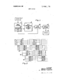
- FIG. I is a block diagram of a display system in which the method of the present inven ql may be employed; 1
- FIG. 2 is a map of information recorded on a storage media. which information is arrangedin accordance with the princi plea of the present invention
- FIG. 3 is an enlarged representation of a portion of the map illustrated in FIG-2;
- I I a a fig. 4 is a partial block and partial schematic disgram of a portion of the data compression and reformat logic illustrated in FIG. I for-one modeof operation of the display system;
- FIG. 5 is a partial block and s partial schematic diagram of for another mode ofoperation ofthe display system.
- cordin'gly it is necessary to either quickly ielejct 1 2x168 bits vof informationout of the 24 million hitsiin the main storage 14 for display on the display unit 169s tocompress aportion or .all of the 24 millionbits of information-in the main storage 7 unit for display in the display unit -l6.
- 'Since"acceptabl'e"s election time of thisinfonnation from the main storage unit l4 is in the order of approximately 10.5 second, the data storage layout' within the storage unit is of critical importance.
- a data compre's'sion'and reformat logic circuit 18 which is under the controljof. theoperator selects-and compresses the data which is to be displayed by meansof the displayunit 16.
- the selected data is supplied to a corememory 20 which acts as a buffer in the transmission of information.
- the information in the core memory 20 is supplied to a display storage unit 12 from which the information is continuously read and supplied as a video signalto the display unit 16."
- it is neceasaryto supply information stored in the core memory 20 to a reformat area 24 on the-magnetic drum in the 7 main storage unit 14 where such information is partially reformatted and supplied through the data compression and reformat logic .circuit 18 and the core memory 20 to the display storage unit 22, v .1 I I
- the system has three modes of operation: namely, display of any one-sixteenth of the microfilrned image, display of anyone-fourth of the microfilmed im'age,- an'ddisplsy of the totalmicrofilmimage; g
- FIG .11 illustrates, 'a representation-ofthe areas of the 'microfilr'nedimage which can be, displayed during the one-sixteenth mode *of operation. During the one-fourth mode. of
- any one of the fourareas in each of the four quadrantsofthe representation illustrated in FIG. 11 can be'displayed.
- the display system is set in a mode todisplay, for example,
- the: only infonnation which is required to bread fromthemain storage unit 14 is one-half of the total lines of the pictorial information and onehalf of the data elements from each of those lines. If successive scan lines of the pictorial information are mapped serially around the periphery of the magnetic drum in the main storage unit 14, useful information would be retrieved therefrom only during one-half of the total read time.
- the present invention substantiallyredtgces amount of time required to retrieve such information from the main storage unit 14 by mapping the information on the magnetic drum in a novel and unique arrangement. Sucharrangement is illustrated in FIG. 2 of the drawings. 1
- the "video information derivedfrom scanning the first of four lines of the microfilmed image is recorded on tracks 26, 28, and 32 to form a block of information designated with the reference numeral 34.
- Each scan line is recorded in 4-bit parallel format, with the result that each block of information is recorded in 16-bit parallel format.
- a subsequent block of scanned information which is formed of scan lines 4, 5, 6 and 7 is recorded on tracks 38, 40, 42 and 44 of the magnetic drum.
- blocks 46 and 48 are each formed of information derived from subsequent scan lines.
- the blocks 34, 3 6, 46 "and 48 are spaced along the path of travel of the magnetic drum from one another by a distance occupied by one-fourth of a line of information plus a relatively small gap to permit switching frorn reading one block to reading a subsequent block.
- FIG. 1 illustrates in greater detail the upper left-hand corner of the recorded information illustrated in FIG. 2.
- the magnetic drum is in a position to permit retrieval of th e'inforrnation from block 36.
- the magnetic drum is ,in a position to permit retrieval of information from the block
- it is desired to display one-fourth of the microfilmed image for example, that portion represented by the areas 50, 52, 54 and 56 in FIG, 1 l it becomes necessary to scan the first one-half of each of the first 2,048 lines of the scanned image.
- the magnetic drum is in a position to permit retrieval of the information in block 46.
- the information retrieved from blocks 34 and 46 form successive lines of one field of the display which is obtained during 1 revolution of the magnetic drum.
- the first half of blocks 36,48, etc. are read to construct the second field of the displayed image.
- the information is stored on the magnetic drum in 16-bit parallel format to form each information block.
- Each successive block of information is spaced from the preceding block along the path of travel of the drum by a distance equal to the distance occupied by 384 bits which correspond to the space occupied by one-fourth of a line of information plus a 32-bit gap for permitting switching from one block of information to another block of information.
- successive blocks of information recorded on the same tracks on the magnetic drum are spaced from one another by a. l28bit gap, such that a 32-bit gap exists between the end of each one-fourth of each block and the beginning of a succeeding block of information.
- a plurality of read-write heads 58ap are employed for writing information on and reading information from the main storage unit 14.
- the number of information bits corresponding to one microfilmed image which are stored on the magnetic drum of the main storage unit 14 are considerably greater than the number of bits employed to construct a display to an operator. if a full frame is to be displayed to the operator, data compression of 64 to 1 must be employed. A quarter picture display requires data compression of 4 to 1. Accordingly, during the one-fourth picture display mode, four immediately adjacent bits are combined to produce a single information bit for display. As shown in FIG.
- each information bit is designatedwith two numbers, the first of which corresponds to the scan line number, and the second of which corresponds to the position of the bit in the corresponding line.
- Information bits (0,0), (0,1), (1,0), and (1,1) correspond to immediately adjacent areas on the microfilmed image. Accordingly, these information bits are combined by connecting the outputs of read heads 58a, 58b, 58, and 58f together to provide an output on a line 60.
- the output on the line 60 will be a l
- the output on the line 60 will be a 0.
- the first output to appear on the line 60 will constitute the first bit of information of the first line to be displayed.
- the second bit of information of the first line which is to be displayed is formed by combining the bits (0,2). (0.3). and 1,3). Therefore, by connecting the outputs of read heads 58c, 584, 58g and 58!! together an output will be provided on a line 62 which corresponds to the combined information contained in these bits.
- this combination of bits of information or compression is performed by OR" gates which are schematically represented by the connection of the outputs of the read heads to one another.
- the output of read heads 58i-p are connected in a similar manner to provide outputs on lines 64 and 66'.
- the initial outputs from lines 64 and 66 form the bits of information which constitute the second line of the ultimate display. Since an interlace system is employed in the display, the initial information provided on the lines 60 and 62 forms the first line of a first field of the display and the initial information provided on the lines 64 and 66 provide the first line of a second field of the display.
- the second line of each field of the display during the onesixteenth picture display mode will be derived from the outputs of the read heads (not shown) associated with tracks 38, 40, 42, and 44 of the magnetic drum.
- the information from each block is combined in the same fashion as described hereinabove for the information in block 34.
- the outputs of all of the read heads 58a-p are connected together as shown in FIG. 5 to form an output on a line 68.
- the OR function provided by connecting the outputs of all of the read heads 58ap together provides a compression of 16 to l by combining 16 immediately adjacent information bits to form a single infonnation bit for display.
- the first .768 bits of information appearing on the line 68 form the first line of the first field of the display.
- the magnetic drum When one-half of the block of information which forms the first line of the first field has been read, the magnetic drum is in a position to read the infonnation from a subsequent block which forms the second line of the first field of the display.
- the first field of the display is constructed during 1 revolution of the magnetic drum and the second field of the display is generated during the second revolution of the magnetic drum.
- the circuit illustrated in FIG. 5 is also employed during the full picture display mode of operation, but the total compression of the infonnation is not perfon'ned therein. Since the compression ratio provided by the circuit illustrated in FIG. 5 is 16 to l, and a compression ratio of 64 to l is required for the full picture display mode of operation, an additional 4 to l compression of the information appearing on the line 68 is required.
- the information derived from the circuits illustrated in FIGS. 4 and 5 must be reformatted before being supplied to the core memory and the display storage unit 22.
- the circuit arrangement illustrated in FIG. 6 is employed for reformatting the data delivered on lines 60, 62, 64 and 66 of FIG. 4.
- a reformat register 70 which is formed of stages 70a--p is connected to respective outputs of the circuit illustrated in FIG. 4 and to respective outputs of a decoder (not shown).
- the terminals designated R1 are connected to line 60
- the terminals designated R2 are connected to line 62
- the terminals designated R3 are connected to line 64
- the terminals designated R4 are connected to line 66.
- the terminals designated T1, T2, T3 and T4 are connected to respective outputs of a decoder (not shown) to control the entry information from the lines Rl-4 into the register stages 70a-p.
- the decoder provides a 4-count cycle which generates a gating pulse during the first count on the terminals Tl, a gating pulse during the second count on the terminals T2, a gating pulse during the third count on the terminals T3, and a gating pulse during the fourth count on the terminals T4.
- FIG. 9 illustrates in block diagram .form the structure of a typical one of the stages 70ap.
- an AND" gate 76 is provided with a pair of inputs, one of which is connected to an input terminal 78 which is disposed for receiving digital bits of information thereon, and the other of which is connected to a terminal T which is disposed for receiving a binary word or gating pulse thereon from adecoder.
- the AND" gate 76 is enabled by the existence of a gating pulse on the terminal T, the binary information appearing at the terminal 78 will be gated to the SET" terminal of a flip-flop 80.
- the state of the flip-flop 80 will be changed to provide a l output on a line 82. If, however, a 0 bit appears at the terminal 78 when the AND" gate 76 is enabled, the state of the flip-flop 80 will remain unchanged and a 0 will appear on the line 82.
- the line 82 is connected to one input of an "AND" gate 84 having another input thereof connected to a terminal C which is disposed for receiving a clock pulse thereon.
- the information on the line 82 is gated to a line 720.
- a reset pulse is supplied to a terminal R which resets the flip-flop 80 to its initial state.
- the initial infonnation appearing on theoutput lines 72 constitutes the first eight bits of the first lineofthe first field of the display and the initial information appearing on the output lines 74 constitutes the first 8 bits of the first line of the second field of the display.
- the information appearing on lines 72 and 74 is supplied to the core memory 20 where it is bufiered and transferred to the display storage 22 and written therein in 8-bit parallel in the format illustrated in. FIG. 10.
- the output circuit for theread heads 58 is as shown in FIG. 5.
- the input circuit for the registe'r 70 is as shown in FIG. 7.
- one input terminal of each of the stages 70a-p is connected to. the terminal 78 which is disposed for receiving digital information from the line 68 (see FIG. 5).
- each of the stages 70a-p is connected to a respective output of a decoder (not shown), such that the first bit of information appearing at the terminal 78 is transferred into the stage 70a, the second bit of information is transferred into the stage 70b, the third bit of information is transferred into the stage 70c, etc.
- the decoder provides a 16 count cycle for entering information into the stages 70a-p in sequential order.
- the first digital word supplied on the output lines 72 constitutes the first 8 bits of the first line of the first field of the display and the initial digital word supplied on the output lines 74 constitutes the second 8 bits of the first line of the first field of th display.
- the magnetic drum is in a position to permit retrieval of the infonnation from block 46, which information is compressed to form the second line of the first field'of the display. Therefore, the first field of the display is developed during a first revolution of the magnetic drum and a second field of the display is developed during a second revolution of the drum by sensing information blocks 36 and 48.
- the input circuit to the refonnat register 70 is changed from that shown in FIGS. 6 and 7 to that shown in FIG. 8.
- Digital information is supplied to the terminal 78 which is connected to one input of each of the register stages 70a-p.
- the other inputs of the stages 70ap are connected to respective pairs of outputs from the decoder (not shown).
- the first 2 bits of information appearing at the terminal 78 are entered into the register stage 700, the second 2 bits are entered into register 70b, etc.
- the entry of 2 bits in succession into a single register stage performs an OR" operation with respect to those 2 bits.
- the flip-fiop80 will not change its state and a "0 second bit entered into the stage 700 will also not affect the state of the flip-flop 80, but a l second bit will change the state of the flip-flop 80.
- the first bit of information entered into the register 70a is a l
- the polarity of the second bit will not affect the altered state of the flip-flop 80. Accordingly, the information supplied on the output lines 72 and 74 is compressed by a ratio of 32 to l with respect to the originally scanned information. Consequently, additional compression is required of this information.
- an output of the core memory 20 is connected to the reformat area 24 on the magnetic drum.
- This loop is employed during the full picture display mode of operation to permit a final compression of the data which is employed to construct a full picture display.
- the information supplied at the output lines 72 and 74 is transferred through the core memory 20 to the reformat area 24.
- the information contained on the output lines 72 and 74 is derived from tracks 26, 28, 30 and 32 of the magnetic drum.
- the information Contained on tracks 38, 40, 42 and 44 must be combined with the previously sensed information. Therefore, during a second revolution of the magnetic drum, the information from block 36 is initially compressed by means of the circuit illustrated in FIG.
- mapping information on a storage media permits rapid access and retrieval of such information for displaying either the whole or a submultiple of the whole of the scanned image. If it is desired to display a smaller than one-sixteenth picture, the distance between the beginning of the block 34 and the beginning of the block 36 can be reduced. For example, if it is desired to display a one sixty-fourth segment of the entire picture, the spacing between the beginning of block 34 and the beginning of block 36 will correspond to the distance occupied by the number of elements in one-eighth of a line segment.
- the information has been shown as arranged in 16-bit parallel format with 4-bit parallel per scan line, it is to be understood that the information blocks may be fonnatted in any convenient or desired arrangement. Furthermore, the information blocks may contain more or less than four scan lines of information.
- a method of mapping information on a movable storage media wherein said information defines n lines of m elements per line of a scanned image for construction of at least one display therefrom which comprises n/x lines of m/y elements per line, wherein x is equal to or greater than unity and equal to or less than n and y is equal to or greater than unity and equal to or less than m, comprising the steps of recording at least one line of said information along at least one track of the storage media, and recording a subsequent line of said information along another track of the storage media and spaced along the path of travel of the storage media from the beginning of the recording of said one line by a distance occupied by m/y elements of information.
- a method of mapping information on and retrieving information from a movable storage media wherein said information comprises n lines of m elements per line of a scanned image, for construction of at least one display therefrom which comprises h/x lines of m/y elements per line, comprising the steps of recording at least one line of said information along at least one track of the stora e media, recording a subsequent lme of said information aong another track of the storage media and spaced along the path of travel of the storage media from the beginning of the recording of said one line by a distance occupied by m/y elements of information, sensing a plurality of elements from said one line, and compressing the data represented by said plurality of elements to form a display information bit.
Abstract
The disclosed embodiment of the present invention is a method of storing pictorial information on and retrieving pictorial information from a movable storage media to permit rapid access and retrieval of such information for displaying either the whole or a submultiple of the whole of the pictorial information in a minimum of time. The disclosed method comprises writing blocks of such information on a magnetic drum, with each block being formed of one or more lines of the scanned information. The blocks are arranged in step fashion on the drum with each successive block being spaced along the direction of travel of the drum a distance equal to the line length of the smallest picture to be displayed. In the disclosed embodiment, each block is formed of four scan lines written in 16-bit parallel format on the drum, and the spacing of each block is equal to the distance occupied by onefourth of a scan line of information. Since the scanned information is greater than the displayed information, that portion of the information which is to be displayed is read from the drum, compressed by means of logic circuits, and supplied to a display storage. The information in the display storage is continuously read and supplied to a CRT for display to an operator.
Description
United States Patent [72] Inventors David C. Jackson Los Altos; Bernie F. Jackson, Cupertino, both of, Calif.
[ll] Appl. No. 809,323
[22] Filed Mar. 21,1969
[45] Patented Aug. 10, I971 [73] Assignee Singer-General Precision, Inc.
Binglumton, N.Y.
[54] METHOD OF STORING INFORMATION ON AND RETRIEYING INFORMATION FROM A MAGNETIC DRUM 5 Claims, 11 Drawing Fip.
[52] US. Cl 340/1725,
[51] Int. GI lb 5/00 [50] Field at Search 340/l72.5,
[56] ReIerences Cited UNITED STATES PATENTS 3,427,596 2/]969 Hertz 340N725 OTHER REFERENCES Svigals, 1., Nonsymmetrical Recording Technique, IBM Technical Disclosure Bulletin, Vol. 9, No. 7, December, 1966, p, 778
Primary Examiner-Raulfe B. Zache Armrneyx- Francis L. Masselle and Willaim Grobman ABSTRACT: The disclosed embodiment of the present invention is a method of storing pictorial information on and retrieving pictorial information from a movable storage media to permit rapid access and retrieval of such information for displaying either the whole or a submultiple of the whole of the pictorial information in a minimum of time. The disclosed method comprises writing blocks of such information on a magnetic drum, with each block being formed of one or more lines of the scanned information. The blocks are arranged in step fashion on the drum with each successive block being spaced along the direction of travel of the drum a distance equal to the line length of the smallest picture to be displayed. In the disclosed embodiment, each block is formed of four scan lines written in [6-bit parallel fonnat on the drum, and the spacing of each block is equal to the distance occupied by one-fourth ofa scan line ofinformation. Since the scanned information is greater than the displayed information, that por tion of the information which is to be displayed is read from the drum, compressed by means of logic circuits, and supplied to a display storage. The information in the display storage is continuously read and supplied to a CRT for display to an operator.
/2 SCANNER MAIN DATA I.20 22 STORAGE in 5 CORE DISPLAY REFORM REFORMAT MEMORY STORAGE AREA LOGIC l is DlSPLAY PATENTEDAUBIOB?! 3,599,178
SHEET 1 BF 4 ,12 SCANNER Fig-1. l4
SHEET LI 0F 4 Flg ii LINE 0 LINE 2 LINE 4 LINE 6 LINE 256 LINE 258 LINE 260 LINE 262 LINE l LINE 3 LINE 5 LINE 7 LINE 257 LINE 259' LINE 26l LINE 263 Fig-1O INVENTORS DAVID G. JACKSON BY BERNIE F. JACKSON displayed.
Msrnoo or sroarncrnsoamrron on AND nsrarsvmc rnroam'rron most A' MAGNETIC This invention relates generally to a'method of storing information on a movable storage media and more particularly to an infonnation storage and retrieval method for a display system which permits rapid construction of a partial display of the entire sore of information. 1 V v Selective mappingof'informstion on a magnetic drum to permit rapid access and retrieval hasheen'employed in the past; However, these prior arrangements usually position the most obvious information to be read successively in serially adjacent areas on the storage media. That is, if pictorial information is to be stored on a magnetic drum, successive scan linesare mapped serially around theperipheryof thedrum. Such mapping of pictorial information, however. does not per mit rapid access and retrieval when either the whole of the pictorial information or a submultiple of the whole of the pictorial information is to be displayed to anjoperator.
If it is desired to displayaportion of theentire pictorial informatiomfor example. one iourth of the total pictorial information, only one-half of'the'informstion' of each scan line is required 'to be read. If pictorial information is written in serial fashionaround the periphery of adrum, each scan line of information must becompletely traversed its entire length before a subsequent scanline 'canbe resd.' Consequerrtly. during adisplay mode in which one-fourth of the total picture is displayed, for esarnple,-u ful information is retrieved only during one-halfof the total time. Y
T Accordingly, the present invention provides a novel arrangement for mapping "pictorial-information on a storage media which permits morerspid andretrieval thereof than prior known mapping arrangements. Generally, the method of the present invention comprises the steps of recording at least a first line of the information alongatleast one track ofthestor'a'ge'media, and recording subsequent line of the information a'long 'another track of the storage. media the drawings are 1-10.37 is a bloc kdiagram'of the manna-register illustrated [in FIG. 6 withthe input circuit be employed with 'the circuit illustrated in FIG. 5 for one-mode 'ofoperation;
FIG. 8' is a block diagram of the reformat "register illustrated -in FIGS. 6 and 7 with'the input circuit-.thereofarranged for being employed with the circuit illustrated in FIG. 5; but in another mode of operation;
FIG; 9 is a block diagram of oneofthe stages of a. refor- ,ma t register illustrated in FIGs: 6,7 unis; Q FIG.' 10 is a map of the pictorial information recorded on the display storage illustrated in'FlGrliand c c FIG; 11 is a representation of theareas. of a pictorial image which can be rapidly displayed to an operatorby employing the principles of the'present inventionin conjunctionwith the display system illustrated, in FIG. .l.-, 1
, Like reference numerals throughout the variousviews of intended to designate the same or similar structures.
With reference to FIG. 1, there is shown a display system in which the method of the present invention may be practiced.
A scanner station; 12 scansadocument such as a microfilm aperture card or the like andsupplies a video signal to a main storage unit 14. Preferably, the main storage unit 14 is formed .of a magneticdrum. The'video signalfisuppliedby the scanner "is in the form of a serial stringof information bitsand the main storage unitjl linclud'es reformat circuitry for'con've'rt ing the serial string of information into-16bit parallel format.
c When all of the pictorisliinforrnation is writtenintoitora'ge, it
is available for ,ret rieval a'nd display tofan operator. I
- In a typical application of the displayssystemillus'trated in FIG. l a microfilm aperture'card is employed which contains pictorial information; such. as line; drawings,.. with the microfilm image'being approximatelyllmillion bits'of data representing image inthe form-.of'a video signal. More specifically, the video-signal is forrned of4,096 lines of information each containing 6,144 hits ofinformation. A display unit le for displaying the pictorial informationto an" operator 1 consists of a television; type scan of 5l 2)t768;lines. Ac-
from the beginning of the recording of the first line by a distance occupied'by number Pf-elements of information corresponding to the line length of the smallest picture to be Accordingly, it is an object of the preaentjinve'ntion to provide a method of mapping pictorisl'information ona storage media which permits relatively rapid access and retrieval thereof for tent, I
"A feature of the present invention resides in the provision of information-blocks which are mapped in stepped fashion on a magnetic drum. such that the first portion of each bloclicorresponding to the length of a step can be ead from the drum during 1 revolution thereof.
These and other objects. features and advantages of the present invention will be-more fully'reelized and understood from the following detailed descriptionwhen taken in conjunction with the accompanylng drawings, wherein:
FIG. I is a block diagram of a display system in which the method of the present inven ql may be employed; 1
FIG. 2 is a map of information recorded on a storage media. which information is arrangedin accordance with the princi plea of the present invention; 7
FIG. 3 is an enlarged representation of a portion of the map illustrated in FIG-2; I I a a fig. 4 is a partial block and partial schematic disgram of a portion of the data compression and reformat logic illustrated in FIG. I for-one modeof operation of the display system;
FIG. 5 is a partial block and s partial schematic diagram of for another mode ofoperation ofthe display system; I
no. a a a block diagram ofanother portion of thedata compression and reformat logic illustrated in FIG-1 which is employed in combination with the circuit illustrated in FIG. 4;
cordin'gly. it is necessary to either quickly ielejct 1 2x168 bits vof informationout of the 24 million hitsiin the main storage 14 for display on the display unit 169s tocompress aportion or .all of the 24 millionbits of information-in the main storage 7 unit for display in the display unit -l6. 'Since"acceptabl'e"s election time of thisinfonnation from the main storage unit l4 is in the order of approximately 10.5 second, the data storage layout' within the storage unit is of critical importance.
A data compre's'sion'and reformat logic circuit 18," which is under the controljof. theoperator selects-and compresses the data which is to be displayed by meansof the displayunit 16. The selected data is supplied to a corememory 20 which acts as a buffer in the transmission of information. The information in the core memory 20 is supplied to a display storage unit 12 from which the information is continuously read and supplied as a video signalto the display unit 16." In one mode of operation it is neceasaryto supply information stored in the core memory 20 to a reformat area 24 on the-magnetic drum in the 7 main storage unit 14 where such information is partially reformatted and supplied through the data compression and reformat logic .circuit 18 and the core memory 20 to the display storage unit 22, v .1 I I Ina specific application-of the display systemillustrated in FIG. I, the system has three modes of operation: namely, display of any one-sixteenth of the microfilrned image, display of anyone-fourth of the microfilmed im'age,- an'ddisplsy of the totalmicrofilmimage; g
FIG .11 illustrates, 'a representation-ofthe areas of the 'microfilr'nedimage which can be, displayed during the one-sixteenth mode *of operation. During the one-fourth mode. of
operation of the display system, any one of the fourareas in each of the four quadrantsofthe representation illustrated in FIG. 11 can be'displayed. I
1f the display system is set in a mode todisplay, for example,
one-fourth of the microfilmed image, the: only infonnation which is required to bread fromthemain storage unit 14 is one-half of the total lines of the pictorial information and onehalf of the data elements from each of those lines. If successive scan lines of the pictorial information are mapped serially around the periphery of the magnetic drum in the main storage unit 14, useful information would be retrieved therefrom only during one-half of the total read time. The present invention substantiallyredtgces amount of time required to retrieve such information from the main storage unit 14 by mapping the information on the magnetic drum in a novel and unique arrangement. Sucharrangement is illustrated in FIG. 2 of the drawings. 1
As shown in FIG. 2, the "video information derivedfrom scanning the first of four lines of the microfilmed image is recorded on tracks 26, 28, and 32 to form a block of information designated with the reference numeral 34. Each scan line is recorded in 4-bit parallel format, with the result that each block of information is recorded in 16-bit parallel format. A subsequent block of scanned information which is formed of scan lines 4, 5, 6 and 7 is recorded on tracks 38, 40, 42 and 44 of the magnetic drum. similarly, blocks 46 and 48 are each formed of information derived from subsequent scan lines. The blocks 34, 3 6, 46 "and 48 are spaced along the path of travel of the magnetic drum from one another by a distance occupied by one-fourth of a line of information plus a relatively small gap to permit switching frorn reading one block to reading a subsequent block.
lf the display system illustrated in FIG. 1 is programmed to display one-sixteenth of the microfilmimage, the mapping arrangement illustrated in FIG. 2 permits rapid access'to any one-fourth line segment without any loss of time between the retrieval of information from one block and the retrieval of information from another block. FIG. 3 illustrates in greater detail the upper left-hand corner of the recorded information illustrated in FIG. 2. l 1
If, for example, it is desired to display the area designated with the reference numeral 50in FIG. 11, which constitutes one-sixteenth of the total image, it is necessary to retrieve from the main storage unit 14 the first one-fourth, of each of the first L024 lines recorded therein. Accordingly, after the first one-fourth of the block 3 4 is read, the magnetic drum is in a position to permit retrieval of th e'inforrnation from block 36. Similarly, after thefu'st one-fourth of block is read from storage, the magnetic drum is ,in a position to permit retrieval of information from the block If it is desired to display one-fourth of the microfilmed image, for example, that portion represented by the areas 50, 52, 54 and 56 in FIG, 1 l it becomes necessary to scan the first one-half of each of the first 2,048 lines of the scanned image. For this example, afier the first half of block 34 is read, the magnetic drum is in a position to permit retrieval of the information in block 46. if an interlace display system is employed, the information retrieved from blocks 34 and 46 form successive lines of one field of the display which is obtained during 1 revolution of the magnetic drum. On a second revolution of the magnetic drum. the first half of blocks 36,48, etc. are read to construct the second field of the displayed image.
If it is desired to display the total microfilm image, 4revolutions of the magnetic drum are required. In each of the above described modes, however, there is no lost time during retrieval in which information must be traversed which is not required for the desired display.
As shown in FIG. 3 of the drawings, the information is stored on the magnetic drum in 16-bit parallel format to form each information block. Each successive block of information is spaced from the preceding block along the path of travel of the drum by a distance equal to the distance occupied by 384 bits which correspond to the space occupied by one-fourth of a line of information plus a 32-bit gap for permitting switching from one block of information to another block of information. Accordingly, successive blocks of information recorded on the same tracks on the magnetic drum are spaced from one another by a. l28bit gap, such that a 32-bit gap exists between the end of each one-fourth of each block and the beginning of a succeeding block of information.
' the invention and is well within the purview of one skilled in the art. However, in-order to understand properly the usefulness of the mapping arrangement of the present invention, a simplified explanation will be made of the more important function of the data compression and reformat logic l8 illustrated in FIG. 1.
With reference to FIGS. 3 and 4, a plurality of read-write heads 58ap are employed for writing information on and reading information from the main storage unit 14. As previously stated, the number of information bits corresponding to one microfilmed image which are stored on the magnetic drum of the main storage unit 14 are considerably greater than the number of bits employed to construct a display to an operator. if a full frame is to be displayed to the operator, data compression of 64 to 1 must be employed. A quarter picture display requires data compression of 4 to 1. Accordingly, during the one-fourth picture display mode, four immediately adjacent bits are combined to produce a single information bit for display. As shown in FIG. 3, each information bit is designatedwith two numbers, the first of which corresponds to the scan line number, and the second of which corresponds to the position of the bit in the corresponding line. Information bits (0,0), (0,1), (1,0), and (1,1) correspond to immediately adjacent areas on the microfilmed image. Accordingly, these information bits are combined by connecting the outputs of read heads 58a, 58b, 58, and 58f together to provide an output on a line 60. Accordingly, if any of these information bits contain a l the output on the line 60 will be a l However, only if all of these information bits are a 0" will the output on the line 60 be a 0." Accordingly, during the one-sixteenth of picture mode of operation, the first output to appear on the line 60 will constitute the first bit of information of the first line to be displayed.
The second bit of information of the first line which is to be displayed is formed by combining the bits (0,2). (0.3). and 1,3). Therefore, by connecting the outputs of read heads 58c, 584, 58g and 58!! together an output will be provided on a line 62 which corresponds to the combined information contained in these bits. In practice, this combination of bits of information or compression is performed by OR" gates which are schematically represented by the connection of the outputs of the read heads to one another.
The output of read heads 58i-p are connected in a similar manner to provide outputs on lines 64 and 66'. The initial outputs from lines 64 and 66 form the bits of information which constitute the second line of the ultimate display. Since an interlace system is employed in the display, the initial information provided on the lines 60 and 62 forms the first line of a first field of the display and the initial information provided on the lines 64 and 66 provide the first line of a second field of the display. I
The second line of each field of the display during the onesixteenth picture display mode will be derived from the outputs of the read heads (not shown) associated with tracks 38, 40, 42, and 44 of the magnetic drum. The information from each block is combined in the same fashion as described hereinabove for the information in block 34.
During the one-quarter picture display mode of operation and the full picture display mode of operation, the outputs of all of the read heads 58a-p are connected together as shown in FIG. 5 to form an output on a line 68. The OR function provided by connecting the outputs of all of the read heads 58ap together provides a compression of 16 to l by combining 16 immediately adjacent information bits to form a single infonnation bit for display. During the one-quarter picture display mode of operation, the first .768 bits of information appearing on the line 68 form the first line of the first field of the display. When one-half of the block of information which forms the first line of the first field has been read, the magnetic drum is in a position to read the infonnation from a subsequent block which forms the second line of the first field of the display. As a result, during the one-quarter picture display mode of operation, the first field of the display is constructed during 1 revolution of the magnetic drum and the second field of the display is generated during the second revolution of the magnetic drum. The circuit illustrated in FIG. 5 is also employed during the full picture display mode of operation, but the total compression of the infonnation is not perfon'ned therein. Since the compression ratio provided by the circuit illustrated in FIG. 5 is 16 to l, and a compression ratio of 64 to l is required for the full picture display mode of operation, an additional 4 to l compression of the information appearing on the line 68 is required.
The information derived from the circuits illustrated in FIGS. 4 and 5 must be reformatted before being supplied to the core memory and the display storage unit 22. For the one-sixteenth picture display mode of operation, the circuit arrangement illustrated in FIG. 6 is employed for reformatting the data delivered on lines 60, 62, 64 and 66 of FIG. 4. A reformat register 70 which is formed of stages 70a--p is connected to respective outputs of the circuit illustrated in FIG. 4 and to respective outputs of a decoder (not shown). In particular, the terminals designated R1 are connected to line 60, the terminals designated R2 are connected to line 62, the terminals designated R3 are connected to line 64, and the terminals designated R4 are connected to line 66. The terminals designated T1, T2, T3 and T4 are connected to respective outputs of a decoder (not shown) to control the entry information from the lines Rl-4 into the register stages 70a-p. The decoder provides a 4-count cycle which generates a gating pulse during the first count on the terminals Tl, a gating pulse during the second count on the terminals T2, a gating pulse during the third count on the terminals T3, and a gating pulse during the fourth count on the terminals T4.
FIG. 9 illustrates in block diagram .form the structure of a typical one of the stages 70ap. As shown therein, an AND" gate 76 is provided with a pair of inputs, one of which is connected to an input terminal 78 which is disposed for receiving digital bits of information thereon, and the other of which is connected to a terminal T which is disposed for receiving a binary word or gating pulse thereon from adecoder. when the AND" gate 76 is enabled by the existence of a gating pulse on the terminal T, the binary information appearing at the terminal 78 will be gated to the SET" terminal of a flip-flop 80. If a 1 bit appears at the input terminal 78 when the "AND" gate 76 is enabled, the state of the flip-flop 80 will be changed to provide a l output on a line 82. If, however, a 0 bit appears at the terminal 78 when the AND" gate 76 is enabled, the state of the flip-flop 80 will remain unchanged and a 0 will appear on the line 82. The line 82 is connected to one input of an "AND" gate 84 having another input thereof connected to a terminal C which is disposed for receiving a clock pulse thereon.
Upon the occurrence of a clock pulse at the terminalC, the information on the line 82 is gated to a line 720. After the information contained in the stage 700 is gated to the output line 72a, a reset pulse is supplied to a terminal R which resets the flip-flop 80 to its initial state.
Therefore, by the time sequenced application of gating pulses to the terminals Tl-4, information is transferred into the register 70. When the register 70 has been filled with infonnation, a clock pulse supplied to the terminal C simultaneously gates all of the information contained therein onto output lines 72 and 74. After the information contained in register 70 is gated to the output lines 72 and 74, a reset pulse is supplied to the terminal R which resets each of the stages 700-1: to their initial state in readiness to receive additional information. In actual practice, two reformat registers 70 are employed, such that information can be supplied to one while information is being removed from the other.
At the beginning of a particular retrieval operation, the initial infonnation appearing on theoutput lines 72 constitutes the first eight bits of the first lineofthe first field of the display and the initial information appearing on the output lines 74 constitutes the first 8 bits of the first line of the second field of the display. The information appearing on lines 72 and 74 is supplied to the core memory 20 where it is bufiered and transferred to the display storage 22 and written therein in 8-bit parallel in the format illustrated in. FIG. 10.
As previously mentioned, during-the one-quarter picture 7 display mode of operation and the full picture display mode of operation, the output circuit for theread heads 58 is as shown in FIG. 5. During the one-quarter picture display mode of operation, the input circuit for the registe'r 70 is as shown in FIG. 7. As shown therein, one input terminal of each of the stages 70a-p is connected to. the terminal 78 which is disposed for receiving digital information from the line 68 (see FIG. 5). The other input terminal of each of the stages 70a-p is connected to a respective output of a decoder (not shown), such that the first bit of information appearing at the terminal 78 is transferred into the stage 70a, the second bit of information is transferred into the stage 70b, the third bit of information is transferred into the stage 70c, etc. In this mode of operation, the decoder provides a 16 count cycle for entering information into the stages 70a-p in sequential order.
At the beginning of a particular retrieval operation, the first digital word supplied on the output lines 72 constitutes the first 8 bits of the first line of the first field of the display and the initial digital word supplied on the output lines 74 constitutes the second 8 bits of the first line of the first field of th display.
As previously mentioned, during the one-quarter picture display mode of operation, one-half of each line length of the first four scan lines is sensed to develop the first line of the first field of the display. After the first half of the first four scan lines are traversed, the magnetic drum is in a position to permit retrieval of the infonnation from block 46, which information is compressed to form the second line of the first field'of the display. Therefore, the first field of the display is developed during a first revolution of the magnetic drum and a second field of the display is developed during a second revolution of the drum by sensing information blocks 36 and 48.
During the full picture display mode of operation, the input circuit to the refonnat register 70 is changed from that shown in FIGS. 6 and 7 to that shown in FIG. 8. Digital information is supplied to the terminal 78 which is connected to one input of each of the register stages 70a-p. The other inputs of the stages 70ap are connected to respective pairs of outputs from the decoder (not shown). As a result, the first 2 bits of information appearing at the terminal 78 are entered into the register stage 700, the second 2 bits are entered into register 70b, etc. In essence, the entry of 2 bits in succession into a single register stage performs an OR" operation with respect to those 2 bits. For example, if the first bit to be entered into register stage 700 is a 0" the flip-fiop80 will not change its state and a "0 second bit entered into the stage 700 will also not affect the state of the flip-flop 80, but a l second bit will change the state of the flip-flop 80. It can be readily appreciated that if the first bit of information entered into the register 70a is a l the polarity of the second bit will not affect the altered state of the flip-flop 80. Accordingly, the information supplied on the output lines 72 and 74 is compressed by a ratio of 32 to l with respect to the originally scanned information. Consequently, additional compression is required of this information.
As shown in FIG. 1, an output of the core memory 20 is connected to the reformat area 24 on the magnetic drum. This loop is employed during the full picture display mode of operation to permit a final compression of the data which is employed to construct a full picture display. The information supplied at the output lines 72 and 74 is transferred through the core memory 20 to the reformat area 24. During a first revolution of the magnetic drum, the information contained on the output lines 72 and 74 is derived from tracks 26, 28, 30 and 32 of the magnetic drum. In order to fonn the first line of the first field of the display, the information Contained on tracks 38, 40, 42 and 44 must be combined with the previously sensed information. Therefore, during a second revolution of the magnetic drum, the information from block 36 is initially compressed by means of the circuit illustrated in FIG. and the reformat register 70 and supplied through the core memory to the reformat area 24. When the information derived from infon'nation block 36 is written into the reformat area 24, it is superimposed on the previously written information derived from the information contained in information block 34. Since only a l information bit is effective to cause a writing operation, any previously recorded 0 information bit will remain unchanged by the presence of a subsequent 0" bit and will be changed by the presence of a subsequent l information bit. However, any previously written 1" information bit will remain unchanged in the presence of any subsequent information bit of either polarity. As a result, an OR" operation is performed during the second write operation within the reformat area 24. Once this information has been completelycompressed within the reformat area 24, it is transferred through the data compression and reformat logic circuit 18 and the core memory 20 to the display storage unit 22.
It can be readily appreciated that the above described method of mapping information on a storage media permits rapid access and retrieval of such information for displaying either the whole or a submultiple of the whole of the scanned image. If it is desired to display a smaller than one-sixteenth picture, the distance between the beginning of the block 34 and the beginning of the block 36 can be reduced. For example, if it is desired to display a one sixty-fourth segment of the entire picture, the spacing between the beginning of block 34 and the beginning of block 36 will correspond to the distance occupied by the number of elements in one-eighth of a line segment. Although the information has been shown as arranged in 16-bit parallel format with 4-bit parallel per scan line, it is to be understood that the information blocks may be fonnatted in any convenient or desired arrangement. Furthermore, the information blocks may contain more or less than four scan lines of information.
The principles of the invention explained in connection with the specific exemplification thereof will suggest many other applications and modifications of the same. It is accordingly desired that, in construing the breadth of the appended claims they shall not be limited to the specific details shown and described in connection with the exemplification thereof.
The invention claimed is:
1. A method of mapping information on a movable storage media, wherein said information defines n lines of m elements per line of a scanned image for construction of at least one display therefrom which comprises n/x lines of m/y elements per line, wherein x is equal to or greater than unity and equal to or less than n and y is equal to or greater than unity and equal to or less than m, comprising the steps of recording at least one line of said information along at least one track of the storage media, and recording a subsequent line of said information along another track of the storage media and spaced along the path of travel of the storage media from the beginning of the recording of said one line by a distance occupied by m/y elements of information.
2. A method as defined in claim 1, wherein x and y are integral numbers.
3. A method as defined in claim 2, wherein x is equal to y.
4. A method of mapping information on and retrieving information from a movable storage media, wherein said information comprises n lines of m elements per line of a scanned image, for construction of at least one display therefrom which comprises h/x lines of m/y elements per line, comprising the steps of recording at least one line of said information along at least one track of the stora e media, recording a subsequent lme of said information aong another track of the storage media and spaced along the path of travel of the storage media from the beginning of the recording of said one line by a distance occupied by m/y elements of information, sensing a plurality of elements from said one line, and compressing the data represented by said plurality of elements to form a display information bit.
5. A method as defined in claim 4, wherein the data is compressed by a factor which is inversely proportional to x.
Claims (5)
1. A method of mapping information on a movable storage media, wherein said information defines n lines of m elements per line of a scanned image for construction of at least one display therefrom which comprises n/x lines of m/y elements per line, wherein x is equal to or greater than unity and equal to or less than n and y is equal to or greater than unity and equal to or less than m, comprising the sTeps of recording at least one line of said information along at least one track of the storage media, and recording a subsequent line of said information along another track of the storage media and spaced along the path of travel of the storage media from the beginning of the recording of said one line by a distance occupied by m/y elements of information.
2. A method as defined in claim 1, wherein x and y are integral numbers.
3. A method as defined in claim 2, wherein x is equal to y.
4. A method of mapping information on and retrieving information from a movable storage media, wherein said information comprises n lines of m elements per line of a scanned image, for construction of at least one display therefrom which comprises n/x lines of m/y elements per line, comprising the steps of recording at least one line of said information along at least one track of the storage media, recording a subsequent line of said information along another track of the storage media and spaced along the path of travel of the storage media from the beginning of the recording of said one line by a distance occupied by m/y elements of information, sensing a plurality of elements from said one line, and compressing the data represented by said plurality of elements to form a display information bit.
5. A method as defined in claim 4, wherein the data is compressed by a factor which is inversely proportional to x.
Applications Claiming Priority (1)
| Application Number | Priority Date | Filing Date | Title |
|---|---|---|---|
| US80932369A | 1969-03-21 | 1969-03-21 |
Publications (1)
| Publication Number | Publication Date |
|---|---|
| US3599178A true US3599178A (en) | 1971-08-10 |
Family
ID=25201055
Family Applications (1)
| Application Number | Title | Priority Date | Filing Date |
|---|---|---|---|
| US809323A Expired - Lifetime US3599178A (en) | 1969-03-21 | 1969-03-21 | Method of storing information on and retrieving information from a magnetic drum |
Country Status (1)
| Country | Link |
|---|---|
| US (1) | US3599178A (en) |
Cited By (23)
| Publication number | Priority date | Publication date | Assignee | Title |
|---|---|---|---|---|
| US3700800A (en) * | 1971-05-18 | 1972-10-24 | Us Air Force | Drum-display synchronizer |
| US3725573A (en) * | 1971-08-31 | 1973-04-03 | Sanders Associates Inc | Video buffer |
| JPS4952948A (en) * | 1972-09-22 | 1974-05-23 | ||
| US3827027A (en) * | 1971-09-22 | 1974-07-30 | Texas Instruments Inc | Method and apparatus for producing variable formats from a digital memory |
| US3872460A (en) * | 1973-04-13 | 1975-03-18 | Harris Intertype Corp | Video layout system |
| US3909512A (en) * | 1972-10-06 | 1975-09-30 | Sanyo Electric Co | Sound information reproducing apparatus for use in a still picture broadcasting system |
| US3996585A (en) * | 1974-06-11 | 1976-12-07 | International Business Machines Corporation | Video generator circuit for a dynamic digital television display |
| US4000510A (en) * | 1975-06-02 | 1976-12-28 | Ampex Corporation | System for storage and retrieval of video information on a cyclical storage device |
| US4028733A (en) * | 1975-07-07 | 1977-06-07 | Telebeam Corporation | Pictorial information retrieval system |
| US4107786A (en) * | 1976-03-01 | 1978-08-15 | Canon Kabushiki Kaisha | Character size changing device |
| US4146874A (en) * | 1978-03-20 | 1979-03-27 | International Business Machines Corporation | Method and apparatus for addressing a character generator |
| US4395738A (en) * | 1980-11-26 | 1983-07-26 | Rca Corporation | Helical scan tape recording and/or replay apparatus |
| US4513390A (en) * | 1979-06-08 | 1985-04-23 | Planning Research Corporation | System for digital transmission and synthesis of integrated data |
| US4593324A (en) * | 1981-04-14 | 1986-06-03 | Fuji Xerox Co., Ltd. | Image data storing device |
| EP0300509A2 (en) * | 1987-07-24 | 1989-01-25 | Matsushita Electric Industrial Co., Ltd. | Display apparatus capable of simultaneously displaying a television picture and a compressed display page of character and graphics data |
| EP0399740A2 (en) * | 1989-05-23 | 1990-11-28 | Matsushita Electric Industrial Co., Ltd. | Character and/or figure displaying apparatus |
| EP0434039A2 (en) * | 1989-12-21 | 1991-06-26 | Matsushita Electric Industrial Co., Ltd. | Character graphic information display device |
| US5132992A (en) * | 1991-01-07 | 1992-07-21 | Paul Yurt | Audio and video transmission and receiving system |
| US5253275A (en) * | 1991-01-07 | 1993-10-12 | H. Lee Browne | Audio and video transmission and receiving system |
| US6002720A (en) * | 1991-01-07 | 1999-12-14 | H. Lee Browne, D/B/A Greenwich Information Technologies Llc | Audio and video transmission and receiving system |
| US6097364A (en) * | 1992-07-29 | 2000-08-01 | Canon Kabushiki Kaisha | Display control apparatus which compresses image data to reduce the size of a display memory |
| US20060136662A1 (en) * | 2004-12-17 | 2006-06-22 | International Business Machines Corporation | Method, apparatus, and computer program product for permitting access to a storage drive while the drive is being formatted |
| US7301944B1 (en) | 1997-10-24 | 2007-11-27 | Tranz-Send Broadcasting Network, Inc. | Media file distribution with adaptive transmission protocols |
Citations (1)
| Publication number | Priority date | Publication date | Assignee | Title |
|---|---|---|---|---|
| US3427596A (en) * | 1967-03-07 | 1969-02-11 | North American Rockwell | System for processing data into an organized sequence of computer words |
-
1969
- 1969-03-21 US US809323A patent/US3599178A/en not_active Expired - Lifetime
Patent Citations (1)
| Publication number | Priority date | Publication date | Assignee | Title |
|---|---|---|---|---|
| US3427596A (en) * | 1967-03-07 | 1969-02-11 | North American Rockwell | System for processing data into an organized sequence of computer words |
Non-Patent Citations (1)
| Title |
|---|
| Svigals, J., Nonsymmetrical Recording Technique, IBM Technical Disclosure Bulletin, Vol. 9, No. 7, December, 1966, p. 778 * |
Cited By (35)
| Publication number | Priority date | Publication date | Assignee | Title |
|---|---|---|---|---|
| US3700800A (en) * | 1971-05-18 | 1972-10-24 | Us Air Force | Drum-display synchronizer |
| US3725573A (en) * | 1971-08-31 | 1973-04-03 | Sanders Associates Inc | Video buffer |
| US3827027A (en) * | 1971-09-22 | 1974-07-30 | Texas Instruments Inc | Method and apparatus for producing variable formats from a digital memory |
| JPS4952948A (en) * | 1972-09-22 | 1974-05-23 | ||
| US3909512A (en) * | 1972-10-06 | 1975-09-30 | Sanyo Electric Co | Sound information reproducing apparatus for use in a still picture broadcasting system |
| US3872460A (en) * | 1973-04-13 | 1975-03-18 | Harris Intertype Corp | Video layout system |
| US3996585A (en) * | 1974-06-11 | 1976-12-07 | International Business Machines Corporation | Video generator circuit for a dynamic digital television display |
| US4000510A (en) * | 1975-06-02 | 1976-12-28 | Ampex Corporation | System for storage and retrieval of video information on a cyclical storage device |
| US4028733A (en) * | 1975-07-07 | 1977-06-07 | Telebeam Corporation | Pictorial information retrieval system |
| US4107786A (en) * | 1976-03-01 | 1978-08-15 | Canon Kabushiki Kaisha | Character size changing device |
| US4146874A (en) * | 1978-03-20 | 1979-03-27 | International Business Machines Corporation | Method and apparatus for addressing a character generator |
| FR2420823A1 (en) * | 1978-03-20 | 1979-10-19 | Ibm | METHOD AND DEVICE FOR ADDRESSING A CHARACTER CELL AND READING THE DATA FROM IT |
| US4513390A (en) * | 1979-06-08 | 1985-04-23 | Planning Research Corporation | System for digital transmission and synthesis of integrated data |
| US4395738A (en) * | 1980-11-26 | 1983-07-26 | Rca Corporation | Helical scan tape recording and/or replay apparatus |
| US4593324A (en) * | 1981-04-14 | 1986-06-03 | Fuji Xerox Co., Ltd. | Image data storing device |
| EP0300509A2 (en) * | 1987-07-24 | 1989-01-25 | Matsushita Electric Industrial Co., Ltd. | Display apparatus capable of simultaneously displaying a television picture and a compressed display page of character and graphics data |
| EP0300509A3 (en) * | 1987-07-24 | 1990-11-28 | Matsushita Electric Industrial Co., Ltd. | Character and graphics data display apparatus having data compression capability |
| EP0399740A2 (en) * | 1989-05-23 | 1990-11-28 | Matsushita Electric Industrial Co., Ltd. | Character and/or figure displaying apparatus |
| US5138450A (en) * | 1989-05-23 | 1992-08-11 | Matsushita Electric Industrial Co., Ltd. | High density character and/or figure displaying apparatus |
| EP0399740A3 (en) * | 1989-05-23 | 1991-01-02 | Matsushita Electric Industrial Co., Ltd. | Character and/or figure displaying apparatus |
| EP0434039A2 (en) * | 1989-12-21 | 1991-06-26 | Matsushita Electric Industrial Co., Ltd. | Character graphic information display device |
| EP0434039A3 (en) * | 1989-12-21 | 1992-09-16 | Matsushita Electric Industrial Co., Ltd. | Character graphic information display device |
| US7673321B2 (en) | 1991-01-07 | 2010-03-02 | Paul Yurt | Audio and video transmission and receiving system |
| US5132992A (en) * | 1991-01-07 | 1992-07-21 | Paul Yurt | Audio and video transmission and receiving system |
| US5253275A (en) * | 1991-01-07 | 1993-10-12 | H. Lee Browne | Audio and video transmission and receiving system |
| US5550863A (en) * | 1991-01-07 | 1996-08-27 | H. Lee Browne | Audio and video transmission and receiving system |
| US6002720A (en) * | 1991-01-07 | 1999-12-14 | H. Lee Browne, D/B/A Greenwich Information Technologies Llc | Audio and video transmission and receiving system |
| US6144702A (en) * | 1991-01-07 | 2000-11-07 | Greenwich Information Technologies, Llc | Audio and video transmission and receiving system |
| US7818773B2 (en) | 1991-01-07 | 2010-10-19 | Acacia Media Technologies Corporation | Audio and video transmission and receiving system |
| US7730512B2 (en) | 1991-01-07 | 2010-06-01 | Acacia Media Technologies Corporation | Audio and video transmission and receiving system |
| US6097364A (en) * | 1992-07-29 | 2000-08-01 | Canon Kabushiki Kaisha | Display control apparatus which compresses image data to reduce the size of a display memory |
| US20080120430A1 (en) * | 1997-10-24 | 2008-05-22 | Redmond Scott D | Peered Content Distribution |
| US7301944B1 (en) | 1997-10-24 | 2007-11-27 | Tranz-Send Broadcasting Network, Inc. | Media file distribution with adaptive transmission protocols |
| US20060136662A1 (en) * | 2004-12-17 | 2006-06-22 | International Business Machines Corporation | Method, apparatus, and computer program product for permitting access to a storage drive while the drive is being formatted |
| US7836247B2 (en) * | 2004-12-17 | 2010-11-16 | International Business Machines Corporation | Method, apparatus, and computer program product for permitting access to a storage drive while the drive is being formatted |
Similar Documents
| Publication | Publication Date | Title |
|---|---|---|
| US3599178A (en) | Method of storing information on and retrieving information from a magnetic drum | |
| US5335299A (en) | Video compression algorithm | |
| US3293614A (en) | Data converter system | |
| US5587726A (en) | Method and apparatus for increasing the speed of operation of a double buffered display system | |
| US5142276A (en) | Method and apparatus for arranging access of vram to provide accelerated writing of vertical lines to an output display | |
| US3836902A (en) | Graphic display having recirculating video memory | |
| US5454071A (en) | Method and apparatus for performing object sorting and edge calculation in a graphic system | |
| US3686631A (en) | Compressed coding of digitized quantities | |
| JPH02502763A (en) | Display cursor pattern generator | |
| US5185859A (en) | Graphics processor, a graphics computer system, and a process of masking selected bits | |
| US3955189A (en) | Data display terminal having data storage and transfer apparatus employing matrix notation addressing | |
| US5265199A (en) | Method and apparatus for accomplishing Z-buffering by prediction | |
| US4570158A (en) | Horizontal and vertical image inversion circuit for a video display | |
| US4910505A (en) | Graphic display apparatus with combined bit buffer and character graphics store | |
| US5818433A (en) | Grapics memory apparatus and method | |
| US3623068A (en) | Serving display functions by means of coded space information | |
| US3432845A (en) | Numeric display | |
| KR960003073B1 (en) | Apparatus for rapidly clearing the output display of a computer system | |
| US3818482A (en) | Character display system | |
| JPS63250689A (en) | Raster scan display system | |
| US4788536A (en) | Method of displaying color picture image and apparatus therefor | |
| JPS61243570A (en) | Form information compression method | |
| KR0170665B1 (en) | Ram for 3-dimensional graphics | |
| JPS60210065A (en) | Picture synthesizer | |
| GB2203317A (en) | Display system |
Legal Events
| Date | Code | Title | Description |
|---|---|---|---|
| AS | Assignment |
Owner name: LINK FLIGHT SIMULATION CORPORATION, KIRKWOOD INDUS Free format text: ASSIGNMENT OF ASSIGNORS INTEREST.;ASSIGNOR:SINGER COMPANY, THE, A NJ CORP.;REEL/FRAME:004998/0190 Effective date: 19880425 |