US3534774A - Pressure compensated control valve - Google Patents
Pressure compensated control valve Download PDFInfo
- Publication number
- US3534774A US3534774A US3534774DA US3534774A US 3534774 A US3534774 A US 3534774A US 3534774D A US3534774D A US 3534774DA US 3534774 A US3534774 A US 3534774A
- Authority
- US
- United States
- Prior art keywords
- valve
- pressure
- passage
- plunger
- fluid
- Prior art date
- Legal status (The legal status is an assumption and is not a legal conclusion. Google has not performed a legal analysis and makes no representation as to the accuracy of the status listed.)
- Expired - Lifetime
Links
Images


Classifications
-
- F—MECHANICAL ENGINEERING; LIGHTING; HEATING; WEAPONS; BLASTING
- F15—FLUID-PRESSURE ACTUATORS; HYDRAULICS OR PNEUMATICS IN GENERAL
- F15B—SYSTEMS ACTING BY MEANS OF FLUIDS IN GENERAL; FLUID-PRESSURE ACTUATORS, e.g. SERVOMOTORS; DETAILS OF FLUID-PRESSURE SYSTEMS, NOT OTHERWISE PROVIDED FOR
- F15B13/00—Details of servomotor systems ; Valves for servomotor systems
- F15B13/02—Fluid distribution or supply devices characterised by their adaptation to the control of servomotors
- F15B13/04—Fluid distribution or supply devices characterised by their adaptation to the control of servomotors for use with a single servomotor
- F15B13/0401—Valve members; Fluid interconnections therefor
- F15B13/0402—Valve members; Fluid interconnections therefor for linearly sliding valves, e.g. spool valves
- F15B13/0403—Valve members; Fluid interconnections therefor for linearly sliding valves, e.g. spool valves a secondary valve member sliding within the main spool, e.g. for regeneration flow
-
- F—MECHANICAL ENGINEERING; LIGHTING; HEATING; WEAPONS; BLASTING
- F15—FLUID-PRESSURE ACTUATORS; HYDRAULICS OR PNEUMATICS IN GENERAL
- F15B—SYSTEMS ACTING BY MEANS OF FLUIDS IN GENERAL; FLUID-PRESSURE ACTUATORS, e.g. SERVOMOTORS; DETAILS OF FLUID-PRESSURE SYSTEMS, NOT OTHERWISE PROVIDED FOR
- F15B13/00—Details of servomotor systems ; Valves for servomotor systems
- F15B13/02—Fluid distribution or supply devices characterised by their adaptation to the control of servomotors
- F15B13/04—Fluid distribution or supply devices characterised by their adaptation to the control of servomotors for use with a single servomotor
- F15B13/0416—Fluid distribution or supply devices characterised by their adaptation to the control of servomotors for use with a single servomotor with means or adapted for load sensing
- F15B13/0417—Load sensing elements; Internal fluid connections therefor; Anti-saturation or pressure-compensation valves
-
- Y—GENERAL TAGGING OF NEW TECHNOLOGICAL DEVELOPMENTS; GENERAL TAGGING OF CROSS-SECTIONAL TECHNOLOGIES SPANNING OVER SEVERAL SECTIONS OF THE IPC; TECHNICAL SUBJECTS COVERED BY FORMER USPC CROSS-REFERENCE ART COLLECTIONS [XRACs] AND DIGESTS
- Y10—TECHNICAL SUBJECTS COVERED BY FORMER USPC
- Y10T—TECHNICAL SUBJECTS COVERED BY FORMER US CLASSIFICATION
- Y10T137/00—Fluid handling
- Y10T137/8593—Systems
- Y10T137/86493—Multi-way valve unit
- Y10T137/86574—Supply and exhaust
- Y10T137/8667—Reciprocating valve
- Y10T137/86694—Piston valve
- Y10T137/86702—With internal flow passage
-
- Y—GENERAL TAGGING OF NEW TECHNOLOGICAL DEVELOPMENTS; GENERAL TAGGING OF CROSS-SECTIONAL TECHNOLOGIES SPANNING OVER SEVERAL SECTIONS OF THE IPC; TECHNICAL SUBJECTS COVERED BY FORMER USPC CROSS-REFERENCE ART COLLECTIONS [XRACs] AND DIGESTS
- Y10—TECHNICAL SUBJECTS COVERED BY FORMER USPC
- Y10T—TECHNICAL SUBJECTS COVERED BY FORMER US CLASSIFICATION
- Y10T137/00—Fluid handling
- Y10T137/8593—Systems
- Y10T137/86493—Multi-way valve unit
- Y10T137/86574—Supply and exhaust
- Y10T137/8667—Reciprocating valve
- Y10T137/86694—Piston valve
- Y10T137/8671—With annular passage [e.g., spool]
-
- Y—GENERAL TAGGING OF NEW TECHNOLOGICAL DEVELOPMENTS; GENERAL TAGGING OF CROSS-SECTIONAL TECHNOLOGIES SPANNING OVER SEVERAL SECTIONS OF THE IPC; TECHNICAL SUBJECTS COVERED BY FORMER USPC CROSS-REFERENCE ART COLLECTIONS [XRACs] AND DIGESTS
- Y10—TECHNICAL SUBJECTS COVERED BY FORMER USPC
- Y10T—TECHNICAL SUBJECTS COVERED BY FORMER US CLASSIFICATION
- Y10T137/00—Fluid handling
- Y10T137/8593—Systems
- Y10T137/87169—Supply and exhaust
- Y10T137/87233—Biased exhaust valve
Definitions
- a hydraulic cylinder control valve having a spool with an orifice to set the rate at which supply fluid flows to the cylinder through either of a pair of service passages.
- a throttle notch in the spool restricts cylinder exhaust flow to an outlet from one of the service passages.
- a first pressure responsive compensating valve mechanism which is actuated in response to change in pressure differential across the orifice maintains supply flow rate at the value set by the valve spool.
- a second pressure compensating valve mechanism is actuated in response to increase in pressure differential across the throttle notch to assure against exhaust flow through said one service passage at a rate any greater than that at which fluid flows to the cylinder through the other service passage.
- This invention relates to pressure compensated control valves of the type having a pair of service passages for connection with the opposite sides of a reversible fluid motor, and it has more particular reference to a control valve by which pressure fluid can be directed to either service passage from the valve. inlet at any of a number of different flow rates and automatically held at the desired rate despite variations in the pressure of the fluid supply or in the load upon the governed motor.
- One hydraulic control valve intended to function in the above described manner is provided with a fluid pressure actuatable main or directional valve spool, and a manually operable pilot valve to effect actuation of the main valve spool from a neutral position to each of a pair of operating positions to selectively direct supply fluid to one or the other of a pair of service passages.
- the pilot is also employed to deliver supply fluid to the selected service passage in an amount determined by the setting of the pilot valve spool.
- a flow divider type compensating valve common to both service passages is responsive to the pressure drop across a metering orifice controlled by the pilot spool, to maintain the rate of fluid flow to the selected service passage at the value set by the pilot spool.
- the compensating valve mechanism also serves as a pump unloader in the neutral position of the main valve.
- a single pressure compensating valve mechanism of the flow divider pump unloading type is also incorporated in a pilot governed directional control valve.
- the pilot valve adjusts the size of an orifice by which a reduced flow of supply fluid to the directional valve spool is established, and the spool then directs the fluid to a selected one of two service passages.
- the pressure compensating valve mechanism functions in response to variations in the pressure drop across the orifice to maintain the flow rate set by the pilot valve at a constant value regardless of fluctuations in the pressure of supply fluid or in the load on the governed motor.
- the flow of supply fluid to the service passages is metered by passage thereof through a throttling groove in the directional control spool itself, but in this case, separate compensating valve devices must be provided for each of the two service passages of the valve.
- a pressure compensated control valve featuring a manually actuatable directional control spool for selectively communicating an inlet passage with either one of a pair of service passages for flow of supply pressure fluid thereto at a rate determined by the extent the spool is displaced out of its neutral position, and wherein a pressure compensating valve mechanism common to both service passages maintains the selected supply flow rate despite variations in the load on the controlled motor or in the pressure of supply fluid entering the control valve inlet.
- a more specific purpose of the invention resides in the provision of a pressure compensated control valve of the closed center type having a land on its directional valve spool which, in neutral, blocks communication between the valve inlet and a feeder passage from which the service passages are supplied, and which land is provided with throttling notches through which supply fluid flows to the feeder passage in either operating position of the valve spool in a metered amount depending upon the extent the spool is displaced from neutral.
- Another object of the invention residesin the provision of a pressure compensated control valve of the character described in the two preceding paragraphs, wherein another pressure compensating valve mechanism regulates flow of return fluid to the valve outlet from one of the service passages of the valve.
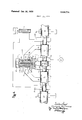
- FlG. l is a diagrammatic view of a pressure compensated control valve of this invention, embodied in a typical hydraulic system;
- FIG. 1 is a fragmentary sectional view illustrating how the mechanism of FIG. 1 can be embodied in a sectional valve assembly
- Fit ⁇ . 3 is a fragmentary diagrammatic view similar to H6. l but illustrating a modified embodiment of the invention
- H65. 4* and 5 are diagrammatic views similar to H0. 3:, but illustrating further modifications of the invention.
- H6. 6 is a fragmentary diagrammatic view, in section, of a modified form of pressure compensating valve mechanism having a dampened compensating plunger;
- HG. 7 is a diagrammatic view similar to FIG. 1, but illustrating a further modification of the invention.
- FIG. ll diagrammatically indicates how a pressure compensated control valve d of this invention can be embodied in a fluid pressure operated system to regulate the rate at which pressure fluid is delivered to a reversible fluid motor such as a double acting hydraulic cylinder 6 from a source, such as a pump 7.
- the body of the control valve 5 contains a valve spool which is slidable axially in a bore 9 from a neutral position shown, to each of a pair of operating positions at opposite sides of neutral.
- a total of eight passages communicates with the bore S at spaced locations along its length. Two of these are paired together and are located at a zone medially of the ends of the bore. One of them provides a supply passage llll which, as indicated, receives pressure fluid from the pump. The other provides a transfer passage llll through which pressure fluid is conducted to a feeder passage 12 downstream therefrom.
- An offset branch T3 of the transfer passage connects with the feeder passage through a load holding check valve M.
- the feeder passage 12 is of inverted U-shape. its legs provide branch passages 15 and 16 which are downstream from the checlr valve 14 and intersect the bore 9 at opposite sides of the medial zone mentioned above. Near its extremities, the bore 9 is intersected by exhaust passages 17 and lid; and at locations intermediate adjacent exhaust passages and feeder branches, the bore is intersected by a pair of service passages 19 and Zll.
- the service passages 19 and 20 may be respectively connected with the head and rod ends of the cylinder in the manner indicated.
- the valve spool 8 has four circumferential grooves ll, 22, 23 and 24 therein at axially spaced locations.
- the two center grooves 22 and 23 define between them a land 25 that serves to bloclr communication between the inlet passage Fill and the transfer passage ll when the valve spool is in its neutral position shown.
- the transfer passage lll ill in effect provides an upstream branch of the feeder passage 12. Also, since in its neutral position the spool 8 prevents communication between the inlet passage 10 and all of the other passages identified above, it will be apparent that the control valve of this invention is of the closed center type.
- the solid end portions 28 of the spool normally block communication between the service passages 19 and Zll and their respective exhaust passages 17 and lift.
- the spool can be shifted from its closed center neutral position shown to a first operating position to the left of neutral to direct pressure fluid from the inlet passage through the upstream and downstream feeder branches 11 and 16, to the rod end of the cylinder 6 by way of service passage 20.
- the spool also directs to the exhaust passage 17 the fluid expelled from the head end of the cylinder and returned to the service passage 19.
- the spool is shifted to a second operating position to the right of neutral, it reverses those cylinder connections to communicate service passage 19 with the inlet passage 10 through feeder branches 11 and 15, while communicating service passage 20 with its adjacent exhaust passage 18.
- pressure fluid is passed from the inlet passage 10 to the upstream feeder branch 11 through a throttling orifice in the center land on the spool, which throttling orifice sets the rate at which pressure fluid flows to the selected service passage.
- a notch formed in the land 25 and extending axially along the periphery thereof from its left hand end provides said orifice when the spool is shifted to its operating position to the right of neutral.
- the notch becomes wider and deeper toward the spool groove 22 to which it opens, so that the rate at which fluid flows therethrough to the upstream branch 11 of the feeder passage increases with the distance the spool is displaced to the right of neutral.
- a similar notch 31 in the land 25 opens to the spool groove 23, and provides an orifice of variable size through which pressure fluid must flow to reach the inlet branch 11 of the feeder passage when the spool is shifted to its operating position to the left of neutral.
- each notch 30-31 can be paired with an identical diametrically opposite notch to provide the orifice whose size is determined by the setting of valve spool 8.
- the rate at which the control spool 8 causes pressure fluid to flow to one or the other of the service passages is maintained constant in any setting of the spool by means of a pressure compensating valve mechanism 33.
- the pressure compensating valve mechanism 33 is located in the valve body to control flow of fluid from the transfer passage 11 to the offset downstream portion 13 thereof. it comprises a hollow cup-like plunger 34 that is axially slidably received in a bore 35 having a reduced but coaxial portion 36 which opens to the transfer passage 11. The other end of the bore 35 is communicated with the inlet passage 10 through a passageway 37.
- the transfer passage is also comprised of portions of bore 35 and its coaxial bore portion 36.
- the compensating plunger 34 is disposed with its closed end or bottom 38 adjacent to the passageway 37. Accordingly, fluid at inlet pressure can at all times act thereon and tend to move it to the left, toward a closed position bridging across the mouth of the offset downstream branch 13 of the transfer passage to close it off from the transfer passage portion 11 upstream therefrom.
- Such response of the plunger 34 to the fluid pressure obtaining in the inlet passage 10 is yieldingly opposed by an expansion spring 40, which urges the plunger toward the right into passageway 37.
- the inlet passage 10 can be substantially relieved of pressure in a known manner, so that the compensating plunger 34 will then occupy a wide open position establishing full communication between the offset portions 11 and 13 of the transfer passage.
- pressure fluid at full pump pressure can be produced in the inlet passage 10 as a consequence of shifting of the directional valve spool 8 to one or the other of its operating positions at which a metered amount of pressure fluid is delivered to a selected one of the service passages through the orifice defined by one of the throttle notches 30 or 31 in the valve spool, for flow to the hydraulic cylinder.
- Pressure of fluid at the upstream side of the orifice in the land 25 will then act upon the compensating plunger to tend to move it to its closed position, while pressure fluid at reduced pressure at the downstream side of said orifice will act opposingly upon the plunger and in concert with spring 40 to tend to move the plunger to its open position.
- the plunger will seek a position intermediate its open and closed positions, at which it will meter fluid flow through a second orifice defined by the mouth of the offset downstream branch 13 of the transfer passage, to an extent depending upon the pressure drop across the upstream orifice defined by the notches (30 or 31) in the center land 25 of the valve spool.
- the plunger will automatically maintain flow of pressure fluid to either service passage at a rate as determined by the extent to which the valve spool 8 is displaced from its neutral position. Moreover, it will do so regardless of variations in the pressure of fluid in the inlet passage 10 or of load produced variations in the pressure of fluid in the feeder passages 11-12.
- the load on the cylinder, in either operating position of the valve spool will determine the pressure at the downstream side of the spool orifice if inlet pressure in passage 10 remains constant.
- the rate of flow to the cylinder as set by adjustment of the directional valve spool 8 will vary with change in load resistance. If the load resistance diminishes, the flow rate will tend to increase and the pressure differential across the spool orifice will increase accordingly. This increase in pressure differential is caused by drop in pressure at the downstream side of the spool orifice while the pressure at its upstream side remains substantially constant. As a result, the compensating plunger 34 responds to the increased pressure differential by moving to the left, in the flow restricting direction, to reduce the rate at which pressure fluid flows past it into the downstream transfer branch 13 from its upstream portion 11 and thereby maintain the desired flow rate to the cylinder.
- the pressure drop across the spool orifice will be varied accordingly to similarly cause a compensating response of plunger 34.
- the plunger will move in the flow restricting direction if the inlet pressure increases, and it will move in the flow increasing direction if inlet pressure decreases.
- the compensating plunger will move to the left, in the flow restricting direction, in accordance with increase in the pressure differential across the spool orifice (30 or 31); and it will move to the right in the flow increasing direction, upon decrease in the pressure differential across the spool orifice.
- pressure fluid flows to the cylinder after passing through a first manually adjustable orifice (30 or 31) in the valve spool itself, and then serially through a second orifice at the mouth of the downstream transfer branch 13, which second orifice is automatically adjustable under the action of the pressure compensating plunger 34.
- FIG. 2 illustrates how pressure compensating valve mechanisms such as described above can be incorporated in a control valve of sectional construction in an exceptionally simple manner.
- the two valve sections therein seen are assembled in stacked relation, and comprise an upstream valve section 5a and an adjoining downstream valve section 5b.
- the section 5b is illustrated as the final control section of a valve bank.
- the inlet passages 10 of the two sections are in full communication with one another across the junction between them. In this way, the inlet passages of all the valve sections of a bank thereof can always be maintained at full pump output pressure.
- Each valve section has its own feeder passage l2 which is communicable with the upstream feeder branch or transfer passage ll of the section through a bore 3'6, transfer branch 13 and check valve id.
- the inlet passageway 37 in each. valve section can open to the upstream face of that section, tobe closed by the downstream face of the adjoining upstream valve section as shown.
- the pressure compensating plunger 34 in each valve section is slidable axially in a bore 35 having its axis crosswise of or perpendicular to that of the bore 9 containing the valve spool 8.
- the bores 35 are also disposed with their axes at right angles to the junctions of the valve sections, and they open toward said junctions, into their respective inlet passageways 37.
- the exhaust passage 17 is also communicable with the exhaust outlet 42. through an annular valve seat provided by the outer end portion of a bore 44 having its inner end in open communication with the service passage 19. As shown, the exhaust outlet opens laterally from one side of the bore 44, downstream from the valve seat A second pressure compensating valve mechanism d7 controls the degree of communication between the exhaust passage 17 and the outlet 42 in accordance with the pressure differential across the throttle notch 43. Like the valve mechanism 33, it also comprises a hollow cup'like plunger 4%, having its closed end. in the service passage l9 and its open end portion movable into and out of engagement with the annular seat 46 to regulate exhaust flow therethrough to the out let 42. A spring 49 yieldingly urges the plunger toward the right, to an open position such as shown, at which exhaust fluid can flow past the open outer end of the plunger to the outlet at.
- the throttle notch 43 may have a diametrically opposite duplicate, as do the notches Eli and Ill. it and its duplicate, if one is provided, can have an appropriate relationship to the orifices 3fl-3-ll in the center land of the spool, so as to allow free exhaust of fluid from the head end of the cylinder in consequence of supply of metered amounts of fluid to its rod end.
- the second pressure compensating valve mechanism 47 acts somewhat in the nature of a counterbalancing valve in that it serves to coordinate exhaust flow of fluid from the cylinder with supply flow thereto. lilowever, it differs from a true counterbalancing valve primarily in that its valve plunger 48 is urged toward a normally open position, whereas the valve element of a counterbalancing valve would normally occupy a closed position.
- FIG. 6 reveals how the pressure compensating valve mechanism 33 of H6. 1 can be modified to prevent hunting and/or flutter of its plunger.
- the valve mechanism i133 seen in FIG. 6 has a plunger 134 like that previously described, to control flow of fluid from the upstream transfer branch ill to iii its downstream branch 113 in accordance with change in pressure differential across the spool orifice Bill or 31.
- the plunger M4 is provided with three coaxial bores.
- the largest diameter bore fill opens toward the transfer passage;
- the second largest diameter bore 52 is intermediate the ends of the plunger and contains a ball check 53 and a biasing spring 54 therefor; and
- the smallest bore opens through the end of the plunger remote from the transfer passage ill and into the branch 37 of the inlet passage l9.
- the plunger biasing spring &0 bears against a perforated washer as and holds the latter against the shoulder defined by the junction between bores 5i and 52.
- the spring 54 is con siderably weaker than the spring 40, and it is confined between the washer S6 and the ball check 53 to yieldingly hold the latter in a closed position extending partly into the smallest bore 55 and engaging the seat provided by the inner end of said bore. Consequently, the ball check 53 precludes flow of pressure fluid from the interior of the plunger M4 to the inlet passageway 37, while allowing flow in the opposite direction into the plunger.
- the plunger biasing spring it is loosely encased in a tube 57 that projects part way into the largest bore fill in the plunger, with a slight clearance space 58 between its exterior and the surrounding wall of the bore.
- the clearance space 553 thus affords such restricted communication between the transfer passage till-t3 and the interior of the plunger as will have a damping or dash pot effect upon the response of the plunger to variations in the pressure differential across the spool orifice Fstl3l. Accordingly, flutter and/or hunting of the plunger is eliminated, and the plunger is substantially stablized in any flow restricting position it may occupy.
- T he control valve seen in H6. 3 is similar to that of hi6. l, but it also has a pressure compensating valve mechanism 23?- of modified construction. its pressure compensating plunger 234 is slidaole in a bore 235 which cuts across the bight of the U-shaped feeder passage 12 and opens downwardly to the transfer passage ll. The axis of bore 235 is thus crosswise of the valve spool d and substantially parallel to the downstream feeder branches l5 and to.
- the bore 235 opens downwardly to the transfer passage ll through a hole at) in the bottom of a ledge 611 that flatwise opposes the open lower end of the plunger 234.
- the other end portion of bore 235 opens upwardly to a pressure chamber '52 which is communicated with the inlet passage ill by means of a duct indicated at l-lence, fluid in chamber 62 will be at a pressure corresponding to that obtaining in the inlet passage lift and will again exert force upon the closed end 238 of the compensating plunger and urge it downwardly, toward the valve spool h, toward a closed position shown at which a portion thereof adjacent to its open end extends across the bight portion of the feeder passage ll2 to block communication between it and the transfer passage ill.
- the cylindrical side wall of the plunger 234 is slidably telescoped over the sleeve 64 of a guide member 65 for a load holding check valve 66 which serves the same purpose as the check valve l4 mentioned hereinbefore.
- the lower end of the sleeve M projects from the compensating plunger and is joined to a head 67 that seats upon the ledge 6t; and it is internally formed with an upwardly facing seat ss for the check valve as.
- the sleeve is also provided with holes 69 just above the check valve seat 68, through which pressure fluid can flow from the transfer passage l l to the space in the lower end por tion of the bore 235 beneath the open lower end of the compensating plunger 2%.
- the upper end of the sleeve 64 is engagable by the closed end 23% of the compensating plunger 2.34 to define the lowermost or closed position of the plunger when the head s7 is seated on its ledge fill. In said closed position, the lower end of the plunger is above the radial holes 69 in the sleeve M, as
- the load holding check valve 66 is also hollow, and a light spring 74 reacting between it and the underside of the washer 72 yieldingly resists upward motion of the check valve off of its seat.
- the compensating valve mechanism 233 also operates to maintain the flow of fluid through either service passage to the hydraulic cylinder at a constant rate determined by the setting of the valve spool 8.
- the compensating plunger will be moved in the closing direction to restrict flow to the feeder passage 12 in response to an increase in the pressure differential across the spool orifice provided by one or the other of the grooves 30 and 31; and the plunger will be moved in the opening direction, to increase flow to the feeder passage 12 in response to a decrease in the pressure differential across the spool orifice.
- the plunger will compensate for whatever change in load resistance caused the change in pressure differential, and flow rate, from that originally selected by the setting of the valve spool 8.
- FIG. 4 discloses how the load holding check valve 76 itself can be mounted in the compensating plunger 334.
- the bore 335 for the compensating plunger opens upwardly to the pressure chamber 62, but it opens downwardly to the transfer passage 11 through a counterbore 77.
- the counterbore 77 opens from an enlarged chamber 78 between the bore 335 and counterbore 77.
- the load holding check valve 76 has an enlarged head 80 which operates in the chamber 78 and is engageable with an upwardly facing valve seat 81 formed at the junction of the counterbore 77 with the chamber 78. When so engaged with its seat, the check valve prevents pressure fluid in the feeder passage 12 from backing up into the transfer passage 11 at times when the compensating plunger 334 is open.
- a sleeve 82 on the check valve extends upwardly from its head 80 and projects telescopically upwardly into the interior of the plunger 334.
- the sleeve terminates short of the closed end of the plunger so that the check valve can open even though the compensating plunger is in its closed position.
- An expansion spring 83 confined between the head 80 of the check valve and the closed end of the compensating plunger tends to axially separate the same. The spring, of course, is relied upon to yieldingly hold the load holding check valve seated and to yieldingly oppose closing motion of the compensating plunger.
- the sleeve 82 is also provided with radial holes 84 therein, near its junction with the head 80 of the valve; and communication is established between the transfer passage 11 and chamber 78 through said holes 84 and a small diameter axial passageway 85 in the valve head, opening to the space inside its sleeve.
- a small upwardly opening pilot ball check valve 86 can be provided to control the axial passageway 85. The ball check, of course, will open whenever pressure fluid enters the transfer passage 11, to allow such fluid to flow through passageway 85 and radial holes 84 to chamber 78 before the head 80 of the load holding check valve is lifted off of its seat by the pressure of fluid entering the transfer passage.
- FIG. 5 discloses still another embodiment of the invention wherein separate load holding check valves 88-89 are provided for the service passages 19-20, respectively. If desired, the check valves 88-89 can be confined within the directional valve spool 90 in a more or less conventional way, as shown.
- the pressure compensating valve mechanism 433 is like that seen in FIG. 1 to the extent that it comprises a hollow cup-like plunger 91.
- the plunger is axially slidably disposed with its closed end 92 uppermost in a bore 93 that extends crosswise of but axially toward the valve spool 90. While one end of the bore terminates in a pressure chamber 62 remote from the valve spool, the other end of the bore opens to the transfer passage 11 through a hole 94 in a ledge 95 which is engageable by the open lower end of the plunger to define its fully closed or lowermost position.
- a compression spring 96 extending up into the interior of the plunger engages its closed end to yieldingly bias the plunger upwardly off of its ledge.
- full pump pressure is at all times imposed upon the closed end of the compensating plunger, by means of a duct 63 that communicates the chamber 62 with the inlet passage 10.
- the compensating plunger is here shown in a completely closed position, which position it would occupy if the control spool were in its neutral position and full pump output pressure obtained in the inlet passage 10 of the control valve. Its operation, of course, will be exactly the same as that of its counterpart in the FIG. 1 embodiment of the invention.
- valve mechanism shown in FIG. 7 is like hat seen in FIG. 1 except that it provides for substantially free flow of return fluid to the outlet at times when a heavy load is imposed upon the cylinder 6. Such a situation could be encountered, for example, when the valve spool is in its left hand operating position directing pump output fluid through service passage 20 to the rod end of the cylinder, and directing exhaust fluid from the head end of the cylinder, returning to service passage 19, to the outlet 42 via exhaust passage 17.
- the exhaust compensating valve mechanism 47 can either be bypassed or rendered ineffective to obstruct exhaust flow to the outlet by means which responds to pressure of fluid in the feeder passage 12, downstream from the pressure compensating valve mechanism 33, in excess of a predetermined high value such as reflects the magnitude of a heavy load upon the cylinder.
- FIG. 7 illustrates how a disabling piston 96 operating in a cylinder 97 can be provided with a stem 98 to engage the plunger 48 of the compensating valve mechanism 47 and render the latter ineffective as soon as the pressure in the feeder passage 12 exceeds a predetermined high value.
- the cylinder 97 is coaxial with the plunger 48 of the compensating valve mechanism 47 and is located opposite the open side of plunger 48 with exhaust passage 17 between the latter and the cylinder.
- the stem 98 extends forwardly from the piston 96 through a close fitting bore 99 in the valve body, into the angular extension 17' of the exhaust passage, and through the annular valve seat 46 to the hollow interior of the I plunger 48.
- the stem terminates short of the bottom 100 of the well in the plunger, and it is encircled by the spring 49 for the latter.
- the length of the stem 98 is such as to cause actuation of the plunger 48 to its wide open position shown when the piston 96 is displaced to its right hand limit of motion in consequence of admittance of pressure fluid into the left hand end of the cylinder.
- a duct ltlll connecting with the left hand end of the cylinder and with the feeder passage 12 is provided for this last named purpose.
- the forward end of the cylinder 97 is preferably vented. as by a duct indicated at 102, communicating with the outlet 42.
- this invention provides an improved control valve wherein a single pressure compensating valve mechanism is able to automatically control the rate at which pressure fluid flows through either of a pair of service passages to one end or the other of a double acting hydraulic cylinder in accordance with the adjustment of an orifice governed by the directional control spool of the control valve; and wherein a second pressure compensating valve mechanism can also govern return flow of fluid from the controlled cylinder to prevent lowering of a load thereon at an excessive rate.
- a control valve of the type having a valve element which is shiftable toward each of a pair of operating positions at opposite sides of a neutral position to direct pressure fluid from an inlet passage to one or the other of a pair of service passages, characterized by:
- A. means constraining pressure fluid flowing to either service passage to pass serially through first and second variable orifices
- the second orifice comprising a compensating valve com.- mon to both service passages and having a pressure responsive plunger for automatically adjusting the size of said second orifice, said plunger being acted upon by pressure of fluid obtaining at the downstream side of the first orifice to be urged thereby in the direction to increase the size of the second orifice;
- E means for translating the pressure of fluid obtaining at the upstream side of said first orifice into a force on the plunger tending to move it in the opposite direction, to decrease the size of the second orifice.
- control valve of claim 1 further characterized by:
- A. feeder passage means having a separate feeder branch for each service passage, through which pressure fluid flows to the latter under the control of the valve element;
- said feeder branches being downstream from said second orifice and the feeder passage means having a common inlet branch that communicates said first and second orifices; and i C. the valve element having orifice defining means thereon that provides said first orifice and restricts fluid flow from the inlet passage to said inlet branch regardless of the direction in which the valve element is shifted out of neutral.
- valve element comprises an axially slidable spool having a land thereon to block communication between the inlet passage and said inlet branch in the neutral position of the spool.
- control valve of claim 7 further characterized by load holding check valve means arranged to open to permit pressure fluid to flow to either service passage from its feeder passage branch.
- valve element directs pressure fluid returning to one of said service passages to an exhaust passage that leads to an outlet, and further characterized by:
- control valve of claim 1 further characterized by means for damping motion of said plunger.
- valve element directs pressure fluid returning to one of said service passages to an exhaust passage that leads to an outlet, and further characterized by:
- valve member to control flow of fluid from the exhaust passage to the outlet, said valve member being movable in response to increase in pressure differential across said throttle groove to restrict fluid flow to the outlet.
- control valve of claim 10 further characterized by means responsive to pressure of fluid above a predetermined high value at the downstream side of said second orifice for substantially freely communicating said one service passage with the outlet.
- control valve of claim 12 wherein said last named means comprises a fluid pressure responsive disabling piston associated with said pressure responsive valve member to acmate the same to an inoperative position in consequence of subjection of the piston to fluid from the downstream side of said second orifice at a pressure exceeding said predetermined high value.
- a control valve of the type having a body with a valve element shiftable from a neutral position toward an operating position at which it directs fluid from a pressure fluid inlet passage to a service passage, characterized by:
- A. means providing a throttling orifice controlled by the valve element, through which pressure fluid flows to said service passage from the inlet passage in said operating position of the valve element, in an amount depending upon the extent the valve element is displaced from neutral;
- a compensating valve mechanism providing an automatically adjustable orifice through which the downstream side of said throttling orifice is communicated with said service passage in said operating position of the valve element, said compensating valve mechanism having a pressure responsive plunger to automatically enlarge and contract said automatically adjustable orifice, depending upon the direction in which the compensating plunger is moved;
- E means for translating pressure of fluid obtaining upstream from said throttling orifice into force on the plunger tending to move it in the direction to contract said automatically adjustable orifice.
- control valve of claim 14 further characterized by:
- feeder passage means in the body having upstream and downstream portions that are respectively communicated with the inlet and service passages by the valve element in said operating position thereof:
- said compensating valve mechanism being located at the junction between the upstream and downstream portions of the feeder passage means to control communication between said portions through said automatically adjustable orifice.
- valve ele-v ment is shiftable toward each of a pair of operating positions at opposite sides of neutral to direct pressure fluid from the inlet passage to one or the other of a pair of service passages, and further characterized by:
- said downstream portion of the feeder passage means comprising a pair of communicated branches. one, for each service passage and selectively communicable therewith by the valve element.
- control valve of claim 14 further characterized by means for damping motion of said pressure responsive plunger.
- a control valve of the type having a body with a valve element shiftable axially in an elongated bore to each of a pair of operating positions at opposite sides of a neutral position to direct pressure fluid from an inlet passage to one or the other of a pair of service passages, characterized by:
- feeder passage means through which pressure fluid flows to either service passage, said feeder passag'e means havmg:
- a pressure responsive plunger for regulating flow to the downstream feeder portions of whatever metered amount of pressure fluid is allowed to enter the upstream feeder portion from the inlet passage via said throttling notches;
- control valve of claim 18 further characterized by check valve means in said upstream feeder portion, upstream from the compensating plunger, arranged to close to prevent reverse flow in the feeder passage means.
- control valve of claim 18. further characterized by:
- A. means upstream from the plunger in said upstream feeder portion providing a valve seat which faces in the downstream direction. and through which pressure fluid admitted to the upstream feeder portion flows in order to exert force on the plunger;
- control valve of claim 20 further characterized by said valve seat being on the valve body and having a diameter greater than that of the plunger.
- control valve of claim 21 further characterized by:
- a control valve of the type having a valve element which is shiftable from one to another of a pair of operating positions to in turn connect each of a pair of service passages with an inlet passage and the other service passage with an outlet connected exhaust passage, characterized by:
- a compensating valve having a pressure responsive plunger for automatically decreasing the size of said second orifice in response to increase in the pressure differential across said first orifice
- D. means operable in response to pressure of fluid above a predetermined high value in the other of said service passages for effecting substantially free communication of said first designated service passage with the outlet.
Description
Applications Claiming Priority (1)
| Application Number | Priority Date | Filing Date | Title |
|---|---|---|---|
| US77564068A | 1968-11-14 | 1968-11-14 |
Publications (1)
| Publication Number | Publication Date |
|---|---|
| US3534774A true US3534774A (en) | 1970-10-20 |
Family
ID=25105025
Family Applications (1)
| Application Number | Title | Priority Date | Filing Date |
|---|---|---|---|
| US3534774D Expired - Lifetime US3534774A (en) | 1968-11-14 | 1968-11-14 | Pressure compensated control valve |
Country Status (6)
| Country | Link |
|---|---|
| US (1) | US3534774A (en) |
| JP (1) | JPS5013964B1 (en) |
| DE (1) | DE1956621A1 (en) |
| FR (1) | FR2023268A1 (en) |
| GB (1) | GB1222779A (en) |
| SE (1) | SE352412B (en) |
Cited By (25)
| Publication number | Priority date | Publication date | Assignee | Title |
|---|---|---|---|---|
| US3635244A (en) * | 1969-01-13 | 1972-01-18 | Lamborghini Oleodinamica | Valve for distributing fluid to a system of fluid-actuated machines |
| US3729026A (en) * | 1971-05-17 | 1973-04-24 | Koehring Co | Control valve with metering type valve spool |
| US3901264A (en) * | 1972-03-06 | 1975-08-26 | Gresen Manufacturing Co | Adjustable flow control for hydraulic valves having high pressure main supply and controls fluid flow to cylinder and exhaust ports |
| US3970108A (en) * | 1973-10-23 | 1976-07-20 | Cross Manufacturing, Inc. | Priority hydraulic control valve |
| US3994314A (en) * | 1975-05-08 | 1976-11-30 | Hartley Ezra D | Servo regulator |
| US4003400A (en) * | 1975-04-07 | 1977-01-18 | The Boeing Company | Self-depressurizing metering valve |
| USRE29538E (en) * | 1971-09-30 | 1978-02-14 | Load responsive fluid control valve | |
| WO1979000947A1 (en) * | 1978-04-19 | 1979-11-15 | Caterpillar Tractor Co | Flow force balanced spool valve |
| US4416189A (en) * | 1982-06-21 | 1983-11-22 | Caterpillar Tractor Co. | Fully compensated fluid control valve |
| US4492080A (en) * | 1979-05-09 | 1985-01-08 | Massey-Ferguson Services N.V. | Tractor hydraulic control systems |
| US4693272A (en) * | 1984-02-13 | 1987-09-15 | Husco International, Inc. | Post pressure compensated unitary hydraulic valve |
| US4889161A (en) * | 1987-10-02 | 1989-12-26 | Applied Power Inc. | Compensated individual segment flow regulator |
| US5067389A (en) * | 1990-08-30 | 1991-11-26 | Caterpillar Inc. | Load check and pressure compensating valve |
| US5248126A (en) * | 1991-09-12 | 1993-09-28 | Volkswagen A.G. | Slide for a slide valve, and method for the manufacture thereof |
| US5305789A (en) * | 1992-04-06 | 1994-04-26 | Rexroth-Sigma | Hydraulic directional control valve combining pressure compensation and maximum pressure selection for controlling a feed pump, and multiple hydraulic control apparatus including a plurality of such valves |
| US20020040603A1 (en) * | 2000-08-23 | 2002-04-11 | Benjamin Kemmner | System and method for optimizing the efficiency of an oil supply |
| US20060144451A1 (en) * | 2003-03-28 | 2006-07-06 | Aisin Seiki Kabushiki Kaisha | Hydraulic pressure control device |
| US20060191582A1 (en) * | 2003-06-04 | 2006-08-31 | Bosch Rexroth Ag | Hydraulic control arrangement |
| US20070028973A1 (en) * | 2003-08-04 | 2007-02-08 | Hitachi Construction Machinery Co., Ltd. | Directional control valve block |
| US20130037131A1 (en) * | 2011-03-16 | 2013-02-14 | Kayaba Industry Co., Ltd. | Control valve |
| CN104912858A (en) * | 2014-03-11 | 2015-09-16 | 布赫液压有限公司 | Hydraulic section for load sensing applications and multiple hydraulic distributor |
| US20160201297A1 (en) * | 2013-08-13 | 2016-07-14 | Volvo Construction Equipment Ab | Flow control valve for construction equipment |
| US10047769B2 (en) * | 2014-04-29 | 2018-08-14 | Volvo Construction Equipment Ab | Flow control valve for construction equipment |
| US10619750B2 (en) * | 2014-06-25 | 2020-04-14 | Parker-Hannifin Corporation | Reverse flow check valve in hydraulic valve with series circuit |
| CN115824480A (en) * | 2023-02-16 | 2023-03-21 | 中感(安徽)矿山技术有限公司 | Quantitative oiling device of borehole stressmeter |
Families Citing this family (5)
| Publication number | Priority date | Publication date | Assignee | Title |
|---|---|---|---|---|
| EP0092074A1 (en) * | 1982-04-19 | 1983-10-26 | Deere & Company | Control valve |
| US4519419A (en) * | 1982-06-15 | 1985-05-28 | Commercial Shearing, Inc. | Hydraulic valves |
| JPS6051862U (en) * | 1983-09-19 | 1985-04-11 | 株式会社東芝 | electromagnetic contactor |
| JPH01145401A (en) * | 1987-10-02 | 1989-06-07 | Applied Power Inc | Flow control valve |
| DE102016007754A1 (en) | 2016-06-24 | 2018-01-11 | Hydac System Gmbh | Valve device for influencing a media flow |
-
1968
- 1968-11-14 US US3534774D patent/US3534774A/en not_active Expired - Lifetime
-
1969
- 1969-11-11 GB GB5517969A patent/GB1222779A/en not_active Expired
- 1969-11-11 DE DE19691956621 patent/DE1956621A1/en active Pending
- 1969-11-12 SE SE1548069A patent/SE352412B/xx unknown
- 1969-11-13 FR FR6939061A patent/FR2023268A1/fr not_active Withdrawn
- 1969-11-14 JP JP9088069A patent/JPS5013964B1/ja active Pending
Cited By (33)
| Publication number | Priority date | Publication date | Assignee | Title |
|---|---|---|---|---|
| US3635244A (en) * | 1969-01-13 | 1972-01-18 | Lamborghini Oleodinamica | Valve for distributing fluid to a system of fluid-actuated machines |
| US3729026A (en) * | 1971-05-17 | 1973-04-24 | Koehring Co | Control valve with metering type valve spool |
| USRE29538E (en) * | 1971-09-30 | 1978-02-14 | Load responsive fluid control valve | |
| US3901264A (en) * | 1972-03-06 | 1975-08-26 | Gresen Manufacturing Co | Adjustable flow control for hydraulic valves having high pressure main supply and controls fluid flow to cylinder and exhaust ports |
| US3970108A (en) * | 1973-10-23 | 1976-07-20 | Cross Manufacturing, Inc. | Priority hydraulic control valve |
| US4003400A (en) * | 1975-04-07 | 1977-01-18 | The Boeing Company | Self-depressurizing metering valve |
| US4127144A (en) * | 1975-04-07 | 1978-11-28 | The Boeing Company | Self-depressurizing metering valve |
| US3994314A (en) * | 1975-05-08 | 1976-11-30 | Hartley Ezra D | Servo regulator |
| WO1979000947A1 (en) * | 1978-04-19 | 1979-11-15 | Caterpillar Tractor Co | Flow force balanced spool valve |
| US4245816A (en) * | 1978-04-19 | 1981-01-20 | Caterpillar Tractor Co. | Flow force balanced spool valve |
| US4492080A (en) * | 1979-05-09 | 1985-01-08 | Massey-Ferguson Services N.V. | Tractor hydraulic control systems |
| US4416189A (en) * | 1982-06-21 | 1983-11-22 | Caterpillar Tractor Co. | Fully compensated fluid control valve |
| US4693272A (en) * | 1984-02-13 | 1987-09-15 | Husco International, Inc. | Post pressure compensated unitary hydraulic valve |
| US4889161A (en) * | 1987-10-02 | 1989-12-26 | Applied Power Inc. | Compensated individual segment flow regulator |
| US5067389A (en) * | 1990-08-30 | 1991-11-26 | Caterpillar Inc. | Load check and pressure compensating valve |
| US5248126A (en) * | 1991-09-12 | 1993-09-28 | Volkswagen A.G. | Slide for a slide valve, and method for the manufacture thereof |
| US5305789A (en) * | 1992-04-06 | 1994-04-26 | Rexroth-Sigma | Hydraulic directional control valve combining pressure compensation and maximum pressure selection for controlling a feed pump, and multiple hydraulic control apparatus including a plurality of such valves |
| US6666225B2 (en) * | 2000-08-23 | 2003-12-23 | Daimlerchrysler Ag | System and method for optimizing the efficiency of an oil supply |
| US20020040603A1 (en) * | 2000-08-23 | 2002-04-11 | Benjamin Kemmner | System and method for optimizing the efficiency of an oil supply |
| US20060144451A1 (en) * | 2003-03-28 | 2006-07-06 | Aisin Seiki Kabushiki Kaisha | Hydraulic pressure control device |
| US20060191582A1 (en) * | 2003-06-04 | 2006-08-31 | Bosch Rexroth Ag | Hydraulic control arrangement |
| US7628174B2 (en) * | 2003-06-04 | 2009-12-08 | Bosch Rexroth Ag | Hydraulic control arrangement |
| US20070028973A1 (en) * | 2003-08-04 | 2007-02-08 | Hitachi Construction Machinery Co., Ltd. | Directional control valve block |
| US20130037131A1 (en) * | 2011-03-16 | 2013-02-14 | Kayaba Industry Co., Ltd. | Control valve |
| US8851119B2 (en) * | 2011-03-16 | 2014-10-07 | Kayaba Industry Co., Ltd. | Control valve |
| US20160201297A1 (en) * | 2013-08-13 | 2016-07-14 | Volvo Construction Equipment Ab | Flow control valve for construction equipment |
| CN104912858A (en) * | 2014-03-11 | 2015-09-16 | 布赫液压有限公司 | Hydraulic section for load sensing applications and multiple hydraulic distributor |
| EP2918853A1 (en) * | 2014-03-11 | 2015-09-16 | Bucher Hydraulics S.p.A. | Hydraulic section for load sensing applications and multiple hydraulic distributor |
| US10100496B2 (en) | 2014-03-11 | 2018-10-16 | Bucher Hydraulics S.P.A. | Hydraulic section for load sensing applications and multiple hydraulic distributor |
| US10047769B2 (en) * | 2014-04-29 | 2018-08-14 | Volvo Construction Equipment Ab | Flow control valve for construction equipment |
| US10619750B2 (en) * | 2014-06-25 | 2020-04-14 | Parker-Hannifin Corporation | Reverse flow check valve in hydraulic valve with series circuit |
| CN115824480A (en) * | 2023-02-16 | 2023-03-21 | 中感(安徽)矿山技术有限公司 | Quantitative oiling device of borehole stressmeter |
| CN115824480B (en) * | 2023-02-16 | 2023-04-18 | 中感(安徽)矿山技术有限公司 | Quantitative oiling device of borehole stressmeter |
Also Published As
| Publication number | Publication date |
|---|---|
| GB1222779A (en) | 1971-02-17 |
| JPS5013964B1 (en) | 1975-05-23 |
| DE1956621A1 (en) | 1970-07-23 |
| SE352412B (en) | 1972-12-27 |
| FR2023268A1 (en) | 1970-08-07 |
Similar Documents
| Publication | Publication Date | Title |
|---|---|---|
| US3534774A (en) | Pressure compensated control valve | |
| US3722543A (en) | Pressure compensated control valve | |
| US5305789A (en) | Hydraulic directional control valve combining pressure compensation and maximum pressure selection for controlling a feed pump, and multiple hydraulic control apparatus including a plurality of such valves | |
| US3718159A (en) | Control valve | |
| US3667722A (en) | Proportional valve | |
| US4145958A (en) | Fluid control system with automatically actuated motor port lock-out valves | |
| US3910311A (en) | Pressure compensated control valve | |
| US4348159A (en) | Convertible pump servo-valve control | |
| US3215236A (en) | Pressure rise delaying valve for hydraulically actuated clutches | |
| US3980095A (en) | Power transmission | |
| US2965133A (en) | Valve | |
| US4095611A (en) | Modulating flow control valve assembly | |
| US4253482A (en) | Hydraulic valve having pressure compensated demand flow | |
| US2593185A (en) | Flow proportioning apparatus | |
| US4065922A (en) | Load lifting and lowering control system | |
| US3770007A (en) | Dual direction flow control valve | |
| US3985153A (en) | Pressure compensating valve spool assembly for a hydraulic control valve | |
| US4275643A (en) | Hydraulic control systems | |
| US3896844A (en) | Fluid flow regulating apparatus | |
| US4178962A (en) | Control valve with flow control means | |
| US3410295A (en) | Regulating valve for metering flow to two hydraulic circuits | |
| US6038957A (en) | Control valves | |
| US4080994A (en) | Control arrangement for supplying pressure fluid to at least two hydraulically operated consumer devices | |
| US3186424A (en) | Hydraulic control valves | |
| US3227179A (en) | Cartridge valves |
Legal Events
| Date | Code | Title | Description |
|---|---|---|---|
| AS | Assignment |
Owner name: KOEHRING COMPANY 200 EXECUTIVE DRIVE, BROOFIELD, W Free format text: ASSIGNMENT OF ASSIGNORS INTEREST.;ASSIGNOR:KOEHRING COMPANY A WI CORP.;REEL/FRAME:003995/0514 Effective date: 19810505 |
|
| AS | Assignment |
Owner name: NORWEST BANK ST. PAUL, NATIONAL ASSOCIATION Free format text: SECURITY INTEREST;ASSIGNOR:HUSCO INTERNATIONAL, INC. A CORP OF DE.;REEL/FRAME:004504/0783 Effective date: 19851206 |
|
| AS | Assignment |
Owner name: NORTHWESTERN NATIONAL LIFE INSURANCE COMPANY, C/O Free format text: MORTGAGE;ASSIGNOR:HUSCO INTERNATIONAL, INC.;REEL/FRAME:004528/0361 Effective date: 19851205 Owner name: HUSCO INTERNATIONAL, INC., W239 N218 PEWAUKEE ROAD Free format text: ASSIGNMENT OF ASSIGNORS INTEREST.;ASSIGNOR:KOEHRING COMPANY, A CORP OF DE.;REEL/FRAME:004509/0989 Effective date: 19851206 |
|
| AS | Assignment |
Owner name: NORWEST BANK MINNESOTA, NATIONAL ASSOCIATION Free format text: SECURITY INTEREST;ASSIGNOR:HUSCO INTERNATIONAL, INC.;REEL/FRAME:005080/0850 Effective date: 19890301 |