US3441281A - Spinner game device - Google Patents
Spinner game device Download PDFInfo
- Publication number
- US3441281A US3441281A US648359A US3441281DA US3441281A US 3441281 A US3441281 A US 3441281A US 648359 A US648359 A US 648359A US 3441281D A US3441281D A US 3441281DA US 3441281 A US3441281 A US 3441281A
- Authority
- US
- United States
- Prior art keywords
- spinner
- wheel
- disc
- data
- game
- Prior art date
- Legal status (The legal status is an assumption and is not a legal conclusion. Google has not performed a legal analysis and makes no representation as to the accuracy of the status listed.)
- Expired - Lifetime
Links
Images
Classifications
-
- A—HUMAN NECESSITIES
- A63—SPORTS; GAMES; AMUSEMENTS
- A63F—CARD, BOARD, OR ROULETTE GAMES; INDOOR GAMES USING SMALL MOVING PLAYING BODIES; VIDEO GAMES; GAMES NOT OTHERWISE PROVIDED FOR
- A63F5/00—Roulette games
- A63F5/04—Disc roulettes; Dial roulettes; Teetotums; Dice-tops
-
- A—HUMAN NECESSITIES
- A63—SPORTS; GAMES; AMUSEMENTS
- A63F—CARD, BOARD, OR ROULETTE GAMES; INDOOR GAMES USING SMALL MOVING PLAYING BODIES; VIDEO GAMES; GAMES NOT OTHERWISE PROVIDED FOR
- A63F3/00—Board games; Raffle games
- A63F3/00003—Types of board games
- A63F3/001—Board games concerning astrology, religion, or fortune-telling
- A63F2003/00104—Board games having astrology aspects
-
- A—HUMAN NECESSITIES
- A63—SPORTS; GAMES; AMUSEMENTS
- A63F—CARD, BOARD, OR ROULETTE GAMES; INDOOR GAMES USING SMALL MOVING PLAYING BODIES; VIDEO GAMES; GAMES NOT OTHERWISE PROVIDED FOR
- A63F11/00—Game accessories of general use, e.g. score counters, boxes
- A63F11/0011—Chance selectors
- A63F2011/0016—Spinners
Definitions
- a game spinner consisting of a housing having a transparent top wall, with a vertical spinner shaft journaled in the housing. Mounted on the shaft is a spinner disc which is provided at its peripheral margin with a series of consecutive numbers.
- a drive wheel is secured on the shaft.
- a plurality of friction driving cams are pivoted in the housing to drivingly-engage the drive wheel.
- the driving cams are provided with pinion gears. Meshing with each pinion gear are opposite rack push bars slidably-mounted in the housing peripheral wall and being arranged so that they can be manually-pushed inwardly, whereby to rotate their associated driving cams.
- An index wheel inscribed with a pointer is rotatably-journaled relative to the spinner shaft and overlies the spinner disc.
- a plurality of additional wheels marked with game data are also journaled for free rotation around the axis of the shaft.
- This invention relates to game devices, and more particularly to an improved game spinner device.
- a main object of the invention is to provide an improved spinner device which may be used in playing various games, such as games wherein a player sets up a specific question and then determines the answers by operating the spinner device, the device being relatively simple in construction, being compact in size, being easy to manipulate, and being usable for a wide range of different types of games.
- a further object of the invention is to provide an improved amusement device in the form of a spinner toy, the device being attractive in appearance, being durable in construction, being simple to adjust, and being adapted for use in a wide range of games, such as in games involving psychological entities or personality aspects, and serving to provide a high degree of amusement and interest for the players involved in such a game.
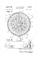
- FIGURE 1 is a top plan view of an improved spinner game device constructed in accordance with the present invention.
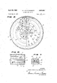
- FIGURE 2 is a front elevational view of the spinner game device of FIGURE 1.
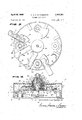
- FIGURE 3 is a horizontal cross-sectional view taken substantially on the line 33 of FIGURE 2.
- FIGURE 4 is a transverse vertical cross-sectional View taken substantially on the line 4-4 of FIGURE 2.
- FIGURE 5 is a horizontal cross-sectional view, with parts broken away, takensubstantially on the line 55 of FIGURE 4.
- FIGURE 6 is a fragmentary vertical cross-sectional view taken substantially on the line 6-6 of FIGURE 3.
- FIGURE 7 is an enlarged cross-sectional detail view taken substantially on the line 77 of FIGURE 4.
- the device 11 generally designates an improved game spinner device constructed in accordance with the present invention.
- the device 11 comprises a generally cylindrical main housing 12 of suitable opaque material, provided with a bottom wall 13.
- the housing 12 is further provided with the transparent, generally circular top wall 14, which may be made of transparent plasice tie material, or any other suitable rigid transparent material.
- Bottom wall 13 is formed with the central upstanding integral pivot cup 15 formed with a central conical pivot recess which rotatably receives the conical bottom end 16 of a vertical spinner shaft 17, said shaft having a conical top end 18 which is pivoted in a spring-biased plunger element 19 slidably-mounted in a downwardlyfacing, generally cylindrical cup member 20.
- a coiled spring 21 is provided in the cup member 20, bearing between the top wall of the cup member and the slidable plunger element 19, biasing the plunger element downwardly so as to maintain it in pivotal engagement with the conical shaft top and 18.
- annular knob element 22 Secured on the top end of the cup member 20 is the annular knob element 22 which is coaxial with spinner shaft 17.
- Disc 23 Rigidly-secured on the lower portion of shaft 17 is the generally circular spinner disc 23 whose diameter is only slightly less than the inside diameter of cylindrical housing 12. Disc 23 is inscribed at its peripheral margin with a series of groups of consecutive numbers 24, which may be employed as reference numbers, in a manner presently to be described, corresponding to answers to questions or problems set up on the device. Said answers are carried by a separate chart, a booklet, or other suitable reference device, not illustrated in the present disclosure.
- a cover sleeve 25 Secured on the cup member 20 is a cover sleeve 25 which is provided at its lower portion with an outwardlyprojecting annular corrugation 26.
- An inner sleeve element 27 is secured in the lower portion of sleeve member 25, said inner sleeve element 27 being provided with the outwardly-projecting bottom flange 28.
- the main sleeve 25 is formed with a bottom flange 29 spaced above flange 28, as shown in FIGURE 4. Interposed between flanges 28 and 29 are a washer 30, an index wheel 31, and a bottom washer 32.
- the index wheel 31 is somewhat smaller than the spinner wheel 23, but is provided with an outwardly-projecting generally triangular pointer element 33 at its periphery, said pointer element overlying the peripheral band of numbers 24 on the spinner disc 23, as shown in FIGURE 1.
- Indicator wheel 31- is freely rotatable relative to sleeves 25 and 27, and, therefore, is freely rotatable relative to knob 22 and spinner disc 23.
- first game-data wheel 34 Rigidly-secured to the lower portion or sleeve 25 is a first game-data wheel 34 which is substantially the same size as the indicator wheel 31 and which overlies same, as shown in FIGURE 4.
- a suitable flat annular bearing washer 35 is interposed between the bottom flange 29 of sleeve 25 and the margin of the central aperture of the data wheel 34, as shown in FIGURE 4.
- data wheel 34 is rigidly-secured in any suitable manner to the lower portion of sleeve 25, so that wheel 34 may be rotated by rotating knob 22.
- the data wheel 34 is inscribed with a series of alphabetical letters '36 located at the peripheral margin of wheel 34, as shown in FIGURE 1.
- the twenty-six letters of the alphabet may be inscribed in sequence on the peripheral margin of the disc member 34, as illustrated in FIGURE 1.
- Rotatably-engaged on and surrounding the sleeve member 25 is a generally cylindrical additional sleeve element 37 provided with an outer shell portion 38 extending downwardly and provided at its bottom end with an outwardly-projecting flange 39 rotatably-supported on a washer 40, which is, in turn, rotatably-supported on the inner portion of the data wheel 34, the inner surface of the depending lower portion of shell 38 being rotatablyengaged with the corrugations 26, whereby to maintain axial alignment of the shell 38 with respect to sleeve 25.
- a second annular knob 40' located subjacent to and concentric with the upper knob 22 and spaced therefrom by an annular bearing ring or washer 42.
- Rigidly-secured to the lower portion of shell member 38 is a second data wheel 43, somewhat smaller in diameter than the lowermost data wheel 34, and spaced therefrom by a bearing washer 44,.
- data wheel 43' is rigidly-secured to sleeve 25, said data wheel may be rotated by rotating the annular knob 40'.
- Data wheel 43 is inscribed at its peripheral margin with additional information, such as the months of the year, arranged consecutively, accompanied by corresponding signs of the zodiac, as shown in FIGURE 1. This data is arranged to appear inwardly adjacent to the alphabetical symbols 36, as shown in FIGURE 1.
- any suitable inscriptions corresponding either to the signs of the zodiac or other identifiable distinct markings, either with or without popular significance may be employed on the data wheel 43.
- Designated at 44 is a third annular member provided with a shell or sleeve 45, the member 44 rotatably-engaging around sleeve 38 and its external shell element 45 extending rotatably through a central aperture provided in the transparent top cover 14, as shown in FIGURE 4.
- Shell member 45 is provided with a bottom flange 46 which is spaced from data wheel 43 by a flat washer 47.
- Rigidly-secured to shell member 45 and substantially slidably and rotatably-engaging beneath the transparent cover member 14 is a third data wheel 48 spaced from flange 46 by a washer 49.
- Data wheel 48 is inscribed with a series of consecutive numbers from O to 9, as is clearly shown in FIGURE 1.
- a third annular knob 50 is secured to the top portion of sleeve element 45, a bearing washer 51 being interposed between the bottom rim of knob 40' and the top end of the composite annular structure defined by ring 44 and sleeve 45. Knob 50 is thus rigidly-connected to data wheel 48 so that wheel 48 may be rotated by rotating knob 50.
- annular member 44 Interposed between annular member 44 and bottom washer 47 are a pair of spacer rings 55, 56 with an intervening annular washer 57.
- Index wheel 31 is formed with three concentric series of upstanding radial lugs, shown respectively at 58, 59 and 60 in FIGURE 5, and the two lower data wheels 43 and 34 are formed with respective circularly-arranged radial slots 61 and 62 registrable with the upstanding lugs 59 and 58, as shown in FIGURE 4.
- the intermediate data wheel 43 is provided with a hinged leaf element 63 which is engageable through a subjacent slot 61 with an upstanding lug 59 of indicator wheel 31, as shown in FIG- URE 7, the member 63 forming part of a hinge assembly which is free to rotate in clockwise direction, as viewed in FIGURE 7, but which is limited in its counterclockwise rotation, for example, by the provision of a stop lug 64 on leaf 63 which limits its counterclockwise rotation to the depending, substantially vertical position thereof shown in FIGURE 7.
- disc 43 is free to rotate in a counterclockwise direction, as viewed in FIG- URE 1, relative to the index wheel 31, but interlocks with said index wheel when it is rotated in a clockwise direction because of the abutment of leaf element 63 with an upstanding lug 59.
- the lowermost data wheel 34 is provided with depending leaf elements 65, similar to leaf elements 63, engageable with upstanding lugs 60 on index wheel 31 and limited in rotation in the same manner as the leaf elements 63, whereby disc 34 is free to rotate in a counterclockwise direction relative to index wheel 31, as viewed in FIGURE 1, but looks with said index wheel because of the engagement of leaf 65 with an upstanding lug 60 when data wheel 34 is rotated clockwise.
- the uppermost data wheel 48 is similarly provided with a depending locking leaf element 65 engageable through a subjacent slot 62 in data wheel 43 and another subjacent slot 61 in data Wheel 34, as shown in FIG- URE 4, and being engageable with an upstanding lug 58 of indicator disc 31 in the same manner as abovedescribed in connection with leaf elements 63 and 65.
- all of the data wheels 34, 43 and 48 are rotatable freely in a counterclockwise direction, as viewed in FIGURE 1, relative to the indicator disc 31, and are also freely rotatable relative to each other in this direction.
- the three concentric data wheels can, therefore, be set to designated positions relative to each other and relative to the indicator pointer 33 by rotating their associated knobs 50, 4t)" and 22 in a counterclockwise direction. Any knob can be rotated counterclockwise by holding any one of the other knobs while the adjustment of the designated knob is made.
- the depending leaf elements 63 and will swing to allow disc 43 or disc 48 to be adjusted counterclockwise relative to disc 34 or relative to index wheel 31, or to allow data wheel 34 to be adjusted relative to index wheel 31, or relative to the other data wheels.
- the data wheels 48, 43 and 34 will remain substantially locked relative to each other and relative to the index pointer 33, and their relative adjustments will not be altered except by subsequent manual actuation of their associated adjusting knobs.
- a friction drive wheel 66 is rigidly-secured to the lower end portion of the spinner shaft 17, the wheel 66 being made of any suitable sturdy material, such as molded plastic, metal, or the like, and being preferably provided with a roughened or knurled periphery.
- a plurality of generally sector-shaped drive cams 67 are respectively pivoted to the bottom wall 13 of housing 12 in positions to frictionally and dirvingly-engage with the drive wheel 66 responsive to inward swinging movements of the drive cams.
- the drive earns 67 are pivoted on respective upstanding shaft elements 68 rigidly-secured to bottom wall 13 at evenly spaced locations around the central axis of shaft 17, the shaft elements 68 being located at equal radial distances from shaft 17 and being located inwardly adjacent the peripheral wall of housing 12, as shown in FIGURE 4.
- the generally sector-shaped cams 67 are provided with arcuate knurled or roughened peripheral edges 69 drivingly-engageable with the periphery of the spinner shaft drive wheel 66, the arcuate surfaces 69 being rotatable substantially into tangential frictional contact with the periphery of wheel 66.
- Respective pinion gear members 70 are keyed to the hub portions of the drive cams 67, the pinion gear members 70 being retained on the upper portions of the shafts 68 by snap rings 71 engaged in annular locking grooves 72 on the top ends of said shafts 68.
- Respective pair of push bars 73 and 74 are provided on opposite sides of the pinion gear members 70, each of the push bars being formed at its inner edge with rack teeth 75 meshingly-cngaging with the adjacent pinion gear member 70, as shown in FIGURE 3.
- the respective pairs of push bars 73, 74 are slidably-supported in apertures 77 provided therefor in the peripheral wall of housing 12, asshown in FIGURE 3.
- the side edges of the push bars remote from the associated pinion gear member 70 are formed with spaced pairs of arcuate recesses 78, 79 adapted to be lockingly-engaged by the respective outwardly-bowed opposite end portions 80, 80 of associated generally U-shaped leaf spring members 81 secured to the inside surface of the peripheral wall of housing 12 between the upstanding shafts 68.
- the bight portions of the springs 81 are secured to the interior peripheral wall surface of housing 12 and the outwardlybowed locking portions 80, 80 engage in adjacent recesses of the push bars, exerting spring force on the push bars and urging them into meshing engagement with the pinion gear elements 70.
- the springs act to position the push bars in either extended or inwardly-moved positions, de-
- guide blocks 82 are provided between the pairs of push bars and between the associated pinion gear elements 70 and the adjacent inner peripheral wall surface of housing 12. The inner edges of the rack bars 73, 74 are in sliding contact with the opposite ends of the generally arcuate spacer blocks 82.
- the pairs of push bars are arranged so that when one push bar is in extended position, the associated other push bar is in inwardly-moved position.
- the crosshatched push bar 73 is shown in an extended position, whereas its associated opposite push bar 74 is in an inwardly-moved position.
- the associated drive cam 67 is rotated in a clockwise direction, as viewed in FIGURE 3, drivingly-engaging the driving wheel 66, whereby to cause the spinner shaft 17 to be rotated in a counterclockwise direction.
- the angle of movement of the drive cams 67 is sufficient to cause them to apply a momentary spin impulse to drive wheel 66 as they swing past the drive wheel 66 during the driving stroke.
- the opposite push bar 74 is extended to a position wherein it can, in turn, be pushed inwardly to provide an opposite driving stroke of the associated drive cam '67.
- the push bars 73, 74 are releasably-locked in either of their two possible normal positions by the engagement of the detent elements 80 in the locking recesses 78, 7-9 of the push bars.
- the biasing springs 81 are sufiiciently flexible to allow the push bars to be pushed inwardly by manual force.
- the rack bars are provided with a suflicient number of teeth 75 and the pinion gear elements 70 are provided with a correspondingly sufficient number of gear teeth to allow the push bars 73, 74 to be moved between their two positional lirnts, namely, the positions corresponding to those wherein the detent elements 80 of the springs engage in either the inner recesses 78 or the outer recesses 79 of the push bars.
- the data wheels 48, 43 and '34 are set with reference to the index pointer element 33 to provide a specified set of data in radial alignment with pointer element 33.
- the data may, for example, correspond to horoscope information pertaining to a particular individiual, or may correspond to a specific set of facts constituting a problem or question to which an answer is desired.
- the setting of the data wheels is accomplished by means of the knobs 22, 40' and 50, which may be suitably rotated to adjust them in relation to the indicator disc 31.
- the player pushes inwardly on one of the extended push bars 73 or 74, pushing the bar sufliciently to move it in-wardly from the position wherein its inner recess 78 is engaged by a detent element 80, to the .position wherein its outer recess 79 receives the detent element.
- This rotates the associated drive arm 67 through a driving stroke, applying a driving impulse to the wheel 66 which causes shaft 17 and spinner disc 23 to be rotated.
- the rotation of the disc 23 occurs in a random manner, so that when the disc comes to rest, the pointer element 3-3 will be positioned opposite a number on the peripheral series of numbers 24.
- the device may be employed in a wide variety of difierent games, since a numbered list of answers can be compiled for different game conditions.
- the device may be employed as a fortune-telling apparatus or for any other entertainment or amusement activity wherein a randomly-determined answer is desired for a specific set of particular facts.
- the various spaces at the periphery of the spinner disc 23 may carry either numbers, as above-mentioned, or may merely comprise colored areas, for example, as shown at 95, employing a number of different colors, for example, five diiferent colors. The significance or meaning of these colored areas is also explained on the accompanying answer sheet.
- a game spinner comprising a support, a vertical spinner shaft journaled on said support, a spinner disc secured on said shaft, said spinner disc being provided at its peripheral margin with markings representing game answers, a drive wheel on said shaft, swingable drive arm means on the support rotatable through driving strokes wherein it is drivingly tangentially-engageable with said drive wheel, means to alternately rotate said drive arm means through said driving strokes in opposite directions, whereby to alternately spin said spinner disc in said opposite directions, lan indicating means including a pointer element overlying said spinner disc and exposing said markings, and question setting means mounted over said indicating means and including a plurality of mutuallyadjustable members having data markings which can be aligned with said pointer element.
- the game spinner of claim 1, and wherein the means to alternately rotate said drive arm means comprises push bar members on opposite sides of the axis of rotation of the drive arm means, and means on the drive arm means in driving engagement with said push bar members.
- said spring means comprises spring arms having outwardlybowed projections, and wherein said rack bars are formed with spaced recesses to receive said projections and to releasably-retain the rack bars in end positions of their operating strokes.
- the game spinner of claim 5, and wherein the support comprises a housing having a vertical peripheral wall and wherein said rack bars are slidably-engaged through said peripheral wall at positions so that at least one rack bar normally projects outwardly from said peripheral wall.
Description
April 29, 1969 H. u. K. w. PANNWITZ SPINNER GAME DEVICE Filed June 23, 1967 1 fdrrae/vf vs. I
April 29, 1969 H. u. K. w. PANNWITZ SPINNER GAME DEVICE Sheet Z of s 7 Filed June 23, 1967 FIG. 6.
United States Patent US. Cl. 273-142 Claim ABSTRACT OF THE DISCLOSURE A game spinner consisting of a housing having a transparent top wall, with a vertical spinner shaft journaled in the housing. Mounted on the shaft is a spinner disc which is provided at its peripheral margin with a series of consecutive numbers. A drive wheel is secured on the shaft. A plurality of friction driving cams are pivoted in the housing to drivingly-engage the drive wheel. The driving cams are provided with pinion gears. Meshing with each pinion gear are opposite rack push bars slidably-mounted in the housing peripheral wall and being arranged so that they can be manually-pushed inwardly, whereby to rotate their associated driving cams. An index wheel inscribed with a pointer is rotatably-journaled relative to the spinner shaft and overlies the spinner disc. A plurality of additional wheels marked with game data are also journaled for free rotation around the axis of the shaft.
This invention relates to game devices, and more particularly to an improved game spinner device.
A main object of the invention is to provide an improved spinner device which may be used in playing various games, such as games wherein a player sets up a specific question and then determines the answers by operating the spinner device, the device being relatively simple in construction, being compact in size, being easy to manipulate, and being usable for a wide range of different types of games.
A further object of the invention is to provide an improved amusement device in the form of a spinner toy, the device being attractive in appearance, being durable in construction, being simple to adjust, and being adapted for use in a wide range of games, such as in games involving psychological entities or personality aspects, and serving to provide a high degree of amusement and interest for the players involved in such a game.
Further objects and advantages of the invention will claims, and from the accompanying drawings, wherein:
FIGURE 1 is a top plan view of an improved spinner game device constructed in accordance with the present invention.
FIGURE 2 is a front elevational view of the spinner game device of FIGURE 1.
FIGURE 3 is a horizontal cross-sectional view taken substantially on the line 33 of FIGURE 2.
FIGURE 4 is a transverse vertical cross-sectional View taken substantially on the line 4-4 of FIGURE 2.
FIGURE 5 is a horizontal cross-sectional view, with parts broken away, takensubstantially on the line 55 of FIGURE 4.
FIGURE 6 is a fragmentary vertical cross-sectional view taken substantially on the line 6-6 of FIGURE 3.
FIGURE 7 is an enlarged cross-sectional detail view taken substantially on the line 77 of FIGURE 4.
Referring to the drawings, 11 generally designates an improved game spinner device constructed in accordance with the present invention. The device 11 comprises a generally cylindrical main housing 12 of suitable opaque material, provided with a bottom wall 13. The housing 12 is further provided with the transparent, generally circular top wall 14, which may be made of transparent plasice tie material, or any other suitable rigid transparent material.
' Bottom wall 13 is formed with the central upstanding integral pivot cup 15 formed with a central conical pivot recess which rotatably receives the conical bottom end 16 of a vertical spinner shaft 17, said shaft having a conical top end 18 which is pivoted in a spring-biased plunger element 19 slidably-mounted in a downwardlyfacing, generally cylindrical cup member 20. A coiled spring 21 is provided in the cup member 20, bearing between the top wall of the cup member and the slidable plunger element 19, biasing the plunger element downwardly so as to maintain it in pivotal engagement with the conical shaft top and 18.
Secured on the top end of the cup member 20 is the annular knob element 22 which is coaxial with spinner shaft 17.
Rigidly-secured on the lower portion of shaft 17 is the generally circular spinner disc 23 whose diameter is only slightly less than the inside diameter of cylindrical housing 12. Disc 23 is inscribed at its peripheral margin with a series of groups of consecutive numbers 24, which may be employed as reference numbers, in a manner presently to be described, corresponding to answers to questions or problems set up on the device. Said answers are carried by a separate chart, a booklet, or other suitable reference device, not illustrated in the present disclosure.
Secured on the cup member 20 is a cover sleeve 25 which is provided at its lower portion with an outwardlyprojecting annular corrugation 26. An inner sleeve element 27 is secured in the lower portion of sleeve member 25, said inner sleeve element 27 being provided with the outwardly-projecting bottom flange 28. The main sleeve 25 is formed with a bottom flange 29 spaced above flange 28, as shown in FIGURE 4. Interposed between flanges 28 and 29 are a washer 30, an index wheel 31, and a bottom washer 32. The index wheel 31 is somewhat smaller than the spinner wheel 23, but is provided with an outwardly-projecting generally triangular pointer element 33 at its periphery, said pointer element overlying the peripheral band of numbers 24 on the spinner disc 23, as shown in FIGURE 1. Indicator wheel 31- is freely rotatable relative to sleeves 25 and 27, and, therefore, is freely rotatable relative to knob 22 and spinner disc 23.
Rigidly-secured to the lower portion or sleeve 25 is a first game-data wheel 34 which is substantially the same size as the indicator wheel 31 and which overlies same, as shown in FIGURE 4. A suitable flat annular bearing washer 35 is interposed between the bottom flange 29 of sleeve 25 and the margin of the central aperture of the data wheel 34, as shown in FIGURE 4. However, data wheel 34 is rigidly-secured in any suitable manner to the lower portion of sleeve 25, so that wheel 34 may be rotated by rotating knob 22.
The data wheel 34 is inscribed with a series of alphabetical letters '36 located at the peripheral margin of wheel 34, as shown in FIGURE 1. Thus, the twenty-six letters of the alphabet may be inscribed in sequence on the peripheral margin of the disc member 34, as illustrated in FIGURE 1.
Rotatably-engaged on and surrounding the sleeve member 25 is a generally cylindrical additional sleeve element 37 provided with an outer shell portion 38 extending downwardly and provided at its bottom end with an outwardly-projecting flange 39 rotatably-supported on a washer 40, which is, in turn, rotatably-supported on the inner portion of the data wheel 34, the inner surface of the depending lower portion of shell 38 being rotatablyengaged with the corrugations 26, whereby to maintain axial alignment of the shell 38 with respect to sleeve 25. Secured on the top end of shell member 38 is a second annular knob 40' located subjacent to and concentric with the upper knob 22 and spaced therefrom by an annular bearing ring or washer 42. Rigidly-secured to the lower portion of shell member 38 is a second data wheel 43, somewhat smaller in diameter than the lowermost data wheel 34, and spaced therefrom by a bearing washer 44,.
Designated at 44 is a third annular member provided with a shell or sleeve 45, the member 44 rotatably-engaging around sleeve 38 and its external shell element 45 extending rotatably through a central aperture provided in the transparent top cover 14, as shown in FIGURE 4. Shell member 45 is provided with a bottom flange 46 which is spaced from data wheel 43 by a flat washer 47. Rigidly-secured to shell member 45 and substantially slidably and rotatably-engaging beneath the transparent cover member 14 is a third data wheel 48 spaced from flange 46 by a washer 49. Data wheel 48 is inscribed with a series of consecutive numbers from O to 9, as is clearly shown in FIGURE 1. These numbers are located inwardly adjacent to the symbols provided on the subjacent data wheel 43. A third annular knob 50 is secured to the top portion of sleeve element 45, a bearing washer 51 being interposed between the bottom rim of knob 40' and the top end of the composite annular structure defined by ring 44 and sleeve 45. Knob 50 is thus rigidly-connected to data wheel 48 so that wheel 48 may be rotated by rotating knob 50.
Interposed between annular member 44 and bottom washer 47 are a pair of spacer rings 55, 56 with an intervening annular washer 57.
Similarly, the lowermost data wheel 34 is provided with depending leaf elements 65, similar to leaf elements 63, engageable with upstanding lugs 60 on index wheel 31 and limited in rotation in the same manner as the leaf elements 63, whereby disc 34 is free to rotate in a counterclockwise direction relative to index wheel 31, as viewed in FIGURE 1, but looks with said index wheel because of the engagement of leaf 65 with an upstanding lug 60 when data wheel 34 is rotated clockwise.
The uppermost data wheel 48 is similarly provided with a depending locking leaf element 65 engageable through a subjacent slot 62 in data wheel 43 and another subjacent slot 61 in data Wheel 34, as shown in FIG- URE 4, and being engageable with an upstanding lug 58 of indicator disc 31 in the same manner as abovedescribed in connection with leaf elements 63 and 65.
It will thus be seen that all of the data wheels 34, 43 and 48 are rotatable freely in a counterclockwise direction, as viewed in FIGURE 1, relative to the indicator disc 31, and are also freely rotatable relative to each other in this direction. The three concentric data wheels can, therefore, be set to designated positions relative to each other and relative to the indicator pointer 33 by rotating their associated knobs 50, 4t)" and 22 in a counterclockwise direction. Any knob can be rotated counterclockwise by holding any one of the other knobs while the adjustment of the designated knob is made. Thus, the depending leaf elements 63 and will swing to allow disc 43 or disc 48 to be adjusted counterclockwise relative to disc 34 or relative to index wheel 31, or to allow data wheel 34 to be adjusted relative to index wheel 31, or relative to the other data wheels. After a setting has been made, the data wheels 48, 43 and 34 will remain substantially locked relative to each other and relative to the index pointer 33, and their relative adjustments will not be altered except by subsequent manual actuation of their associated adjusting knobs.
A friction drive wheel 66 is rigidly-secured to the lower end portion of the spinner shaft 17, the wheel 66 being made of any suitable sturdy material, such as molded plastic, metal, or the like, and being preferably provided with a roughened or knurled periphery. A plurality of generally sector-shaped drive cams 67 are respectively pivoted to the bottom wall 13 of housing 12 in positions to frictionally and dirvingly-engage with the drive wheel 66 responsive to inward swinging movements of the drive cams. Thus, the drive earns 67 are pivoted on respective upstanding shaft elements 68 rigidly-secured to bottom wall 13 at evenly spaced locations around the central axis of shaft 17, the shaft elements 68 being located at equal radial distances from shaft 17 and being located inwardly adjacent the peripheral wall of housing 12, as shown in FIGURE 4. The generally sector-shaped cams 67 are provided with arcuate knurled or roughened peripheral edges 69 drivingly-engageable with the periphery of the spinner shaft drive wheel 66, the arcuate surfaces 69 being rotatable substantially into tangential frictional contact with the periphery of wheel 66. Respective pinion gear members 70 are keyed to the hub portions of the drive cams 67, the pinion gear members 70 being retained on the upper portions of the shafts 68 by snap rings 71 engaged in annular locking grooves 72 on the top ends of said shafts 68.
Respective pair of push bars 73 and 74 are provided on opposite sides of the pinion gear members 70, each of the push bars being formed at its inner edge with rack teeth 75 meshingly-cngaging with the adjacent pinion gear member 70, as shown in FIGURE 3. The respective pairs of push bars 73, 74 are slidably-supported in apertures 77 provided therefor in the peripheral wall of housing 12, asshown in FIGURE 3.
The side edges of the push bars remote from the associated pinion gear member 70 are formed with spaced pairs of arcuate recesses 78, 79 adapted to be lockingly-engaged by the respective outwardly-bowed opposite end portions 80, 80 of associated generally U-shaped leaf spring members 81 secured to the inside surface of the peripheral wall of housing 12 between the upstanding shafts 68. Thus, as shown in FIGURE 3, the bight portions of the springs 81 are secured to the interior peripheral wall surface of housing 12 and the outwardlybowed locking portions 80, 80 engage in adjacent recesses of the push bars, exerting spring force on the push bars and urging them into meshing engagement with the pinion gear elements 70. The springs act to position the push bars in either extended or inwardly-moved positions, de-
pending upon whether the bowed detent elements 80 engage in the inner recesses 78 or the outer recesses 79 of the push bars. As shown in FIGURES 3 and 4, guide blocks 82 are provided between the pairs of push bars and between the associated pinion gear elements 70 and the adjacent inner peripheral wall surface of housing 12. The inner edges of the rack bars 73, 74 are in sliding contact with the opposite ends of the generally arcuate spacer blocks 82.
As will be seen from FIGURE 3, the pairs of push bars are arranged so that when one push bar is in extended position, the associated other push bar is in inwardly-moved position. Thus, in FIGURE 3, the crosshatched push bar 73 is shown in an extended position, whereas its associated opposite push bar 74 is in an inwardly-moved position. When said push bar 73 is pushed inwardly, the associated drive cam 67 is rotated in a clockwise direction, as viewed in FIGURE 3, drivingly-engaging the driving wheel 66, whereby to cause the spinner shaft 17 to be rotated in a counterclockwise direction. The angle of movement of the drive cams 67 is sufficient to cause them to apply a momentary spin impulse to drive wheel 66 as they swing past the drive wheel 66 during the driving stroke. Concurrently with this stroke of the drive cam '67, the opposite push bar 74 is extended to a position wherein it can, in turn, be pushed inwardly to provide an opposite driving stroke of the associated drive cam '67. As above-mentioned, the push bars 73, 74 are releasably-locked in either of their two possible normal positions by the engagement of the detent elements 80 in the locking recesses 78, 7-9 of the push bars. The biasing springs 81 are sufiiciently flexible to allow the push bars to be pushed inwardly by manual force. The rack bars are provided with a suflicient number of teeth 75 and the pinion gear elements 70 are provided with a correspondingly sufficient number of gear teeth to allow the push bars 73, 74 to be moved between their two positional lirnts, namely, the positions corresponding to those wherein the detent elements 80 of the springs engage in either the inner recesses 78 or the outer recesses 79 of the push bars.
in using the device, the data wheels 48, 43 and '34 are set with reference to the index pointer element 33 to provide a specified set of data in radial alignment with pointer element 33. The data may, for example, correspond to horoscope information pertaining to a particular individiual, or may correspond to a specific set of facts constituting a problem or question to which an answer is desired. As above-mentioned, the setting of the data wheels is accomplished by means of the knobs 22, 40' and 50, which may be suitably rotated to adjust them in relation to the indicator disc 31.
After the setting of the data wheels with respect to the indicator disc has been completed, the player pushes inwardly on one of the extended push bars 73 or 74, pushing the bar sufliciently to move it in-wardly from the position wherein its inner recess 78 is engaged by a detent element 80, to the .position wherein its outer recess 79 receives the detent element. This rotates the associated drive arm 67 through a driving stroke, applying a driving impulse to the wheel 66 which causes shaft 17 and spinner disc 23 to be rotated. The rotation of the disc 23 occurs in a random manner, so that when the disc comes to rest, the pointer element 3-3 will be positioned opposite a number on the peripheral series of numbers 24. By consulting the accompanying numbered list of answers, the answer corresponding to the designated number can be read off.
As will be readily apparent, the device may be employed in a wide variety of difierent games, since a numbered list of answers can be compiled for different game conditions. For example, the device may be employed as a fortune-telling apparatus or for any other entertainment or amusement activity wherein a randomly-determined answer is desired for a specific set of particular facts.
The various spaces at the periphery of the spinner disc 23 may carry either numbers, as above-mentioned, or may merely comprise colored areas, for example, as shown at 95, employing a number of different colors, for example, five diiferent colors. The significance or meaning of these colored areas is also explained on the accompanying answer sheet. In the typical example illustrate-d in FIGURE 1, there are twenty colored areas 95. Of these, eight may be blue, five may be green, five may be yellow, one may be orange, and one may be red, shown at 96, which may be specified as the starting point of the pointer element 33.
It will be readily apparent that a large number of structural modifications may be introduced into the construction of the device above-described, for example, the various sleeve elements associated with the knobs 22, 40' and 50, for example, the sleeve elements 25, 38 and 45 may be notched or slot-ted vertically, as shown at 97 in FIGURE 5.
While a specific embodiment of an improved game spinner device has been disclosed in the foregoing description, it will be understood that various modifications within the spirit of the invention may occur to those skilled in the art. Therefore, it is intended that no limitations be placed on the invention except as defined by the scope of the appended claims.
What is claimed is:
'1. A game spinner comprising a support, a vertical spinner shaft journaled on said support, a spinner disc secured on said shaft, said spinner disc being provided at its peripheral margin with markings representing game answers, a drive wheel on said shaft, swingable drive arm means on the support rotatable through driving strokes wherein it is drivingly tangentially-engageable with said drive wheel, means to alternately rotate said drive arm means through said driving strokes in opposite directions, whereby to alternately spin said spinner disc in said opposite directions, lan indicating means including a pointer element overlying said spinner disc and exposing said markings, and question setting means mounted over said indicating means and including a plurality of mutuallyadjustable members having data markings which can be aligned with said pointer element.
2. The game spinner of claim 1, and wherein the means to alternately rotate said drive arm means comprises push bar members on opposite sides of the axis of rotation of the drive arm means, and means on the drive arm means in driving engagement with said push bar members.
3. The game spinner of claim El, and wherein the drive arm means is provided with a pinion gear element coaxial with its axis of rotation and said means to alternately rotate the drive arm means comprises rack bars on opposite sides of said axis movably-supported on said support and meshingly-engaged with said pinion gear element.
4. The game spinner of claim 3, and spring means urging the rack bars against the pinion gear element.
5. The game spinner of claim 4, and wherein said spring means comprises spring arms having outwardlybowed projections, and wherein said rack bars are formed with spaced recesses to receive said projections and to releasably-retain the rack bars in end positions of their operating strokes.
6. The game spinner of claim 5, and wherein the support comprises a housing having a vertical peripheral wall and wherein said rack bars are slidably-engaged through said peripheral wall at positions so that at least one rack bar normally projects outwardly from said peripheral wall.
'-7. The game spinner of claim 6, and wherein the spaced recesses are located in the side edges of the rack bars remote from the associated pinion gear element.
8. The game spinner of claim 7, and wherein said mutually adjustable members comprise additional discs graduated in size rotat'ably-mounted coaxially with said spinner disc, and wherein said indicating means comprises a further disc member also coaxial with said spinner disc.
9. The game spinner of claim 8, and depending rotatable projections on said additional discs, and upstanding means on said further disc member engageable with said depending projections, and means to limit rotation of said depending projections so as to limit rotation of said additional discs relative to said further disc member to one direction.
10. The game spinner of claim 9, and concentric adjusting knobs connected to said additional discs for adjusting them relative to each other and relative to said pointer element.
References Cited UNITED STATES PATENTS 1,550,101 8/1925 Schenck 273---161 2,097,161 10/1937 Mason 273-142 2,441,074 5/1948 Kirkpatrick a- 273l42 X 3,355,822 12/1967 Losey 3544 10 ANTON O. OECHSLE, Primary Examiner.
US. Cl. X.R.
Applications Claiming Priority (1)
| Application Number | Priority Date | Filing Date | Title |
|---|---|---|---|
| US64835967A | 1967-06-23 | 1967-06-23 |
Publications (1)
| Publication Number | Publication Date |
|---|---|
| US3441281A true US3441281A (en) | 1969-04-29 |
Family
ID=24600478
Family Applications (1)
| Application Number | Title | Priority Date | Filing Date |
|---|---|---|---|
| US648359A Expired - Lifetime US3441281A (en) | 1967-06-23 | 1967-06-23 | Spinner game device |
Country Status (1)
| Country | Link |
|---|---|
| US (1) | US3441281A (en) |
Cited By (7)
| Publication number | Priority date | Publication date | Assignee | Title |
|---|---|---|---|---|
| US4732386A (en) * | 1986-02-19 | 1988-03-22 | Howard Rayfiel | Visible randomly intermeshing, multi-wheel chance game apparatus |
| US4911448A (en) * | 1989-08-14 | 1990-03-27 | Benny Thomas | Spinner device |
| US5118110A (en) * | 1990-03-07 | 1992-06-02 | Jones Roy A | Lottery select game |
| US5687967A (en) * | 1994-09-29 | 1997-11-18 | Anette Klaus | Roulette equipment |
| US20080067741A1 (en) * | 2006-08-08 | 2008-03-20 | Richard Eckhardt | Low profile random selection spinner wheel |
| US20110163497A1 (en) * | 2010-01-06 | 2011-07-07 | Hancock Eric A | Three Dimensional Random Number Generator |
| JP6472500B1 (en) * | 2017-11-10 | 2019-02-20 | 株式会社バンダイ | Roulette toy |
Citations (4)
| Publication number | Priority date | Publication date | Assignee | Title |
|---|---|---|---|---|
| US1550101A (en) * | 1925-01-27 | 1925-08-18 | Jay E Schenck | Fortune-telling game |
| US2097161A (en) * | 1935-11-02 | 1937-10-26 | Charles D Mason | Amusement device |
| US2441074A (en) * | 1945-12-17 | 1948-05-04 | James E Kirkpatrick | Game |
| US3355822A (en) * | 1965-10-23 | 1967-12-05 | Losey Alba Elinor | Astrologic device |
-
1967
- 1967-06-23 US US648359A patent/US3441281A/en not_active Expired - Lifetime
Patent Citations (4)
| Publication number | Priority date | Publication date | Assignee | Title |
|---|---|---|---|---|
| US1550101A (en) * | 1925-01-27 | 1925-08-18 | Jay E Schenck | Fortune-telling game |
| US2097161A (en) * | 1935-11-02 | 1937-10-26 | Charles D Mason | Amusement device |
| US2441074A (en) * | 1945-12-17 | 1948-05-04 | James E Kirkpatrick | Game |
| US3355822A (en) * | 1965-10-23 | 1967-12-05 | Losey Alba Elinor | Astrologic device |
Cited By (8)
| Publication number | Priority date | Publication date | Assignee | Title |
|---|---|---|---|---|
| US4732386A (en) * | 1986-02-19 | 1988-03-22 | Howard Rayfiel | Visible randomly intermeshing, multi-wheel chance game apparatus |
| US4911448A (en) * | 1989-08-14 | 1990-03-27 | Benny Thomas | Spinner device |
| US5118110A (en) * | 1990-03-07 | 1992-06-02 | Jones Roy A | Lottery select game |
| US5687967A (en) * | 1994-09-29 | 1997-11-18 | Anette Klaus | Roulette equipment |
| US20080067741A1 (en) * | 2006-08-08 | 2008-03-20 | Richard Eckhardt | Low profile random selection spinner wheel |
| US20110163497A1 (en) * | 2010-01-06 | 2011-07-07 | Hancock Eric A | Three Dimensional Random Number Generator |
| US8448945B2 (en) * | 2010-01-06 | 2013-05-28 | Eric A. HANCOCK | Three dimensional random number generator |
| JP6472500B1 (en) * | 2017-11-10 | 2019-02-20 | 株式会社バンダイ | Roulette toy |
Similar Documents
| Publication | Publication Date | Title |
|---|---|---|
| US4890845A (en) | Game apparatus with rotating elements | |
| KR930010039B1 (en) | Rotator game device | |
| US4468033A (en) | Object transfer toy utilizing gears for component coordination | |
| US3441281A (en) | Spinner game device | |
| DK1981603T3 (en) | An apparatus that is useful as a toy, or teaching device puslespils- | |
| US1985652A (en) | Tennis scoring device | |
| US4875675A (en) | Skipping toy and method of playing same | |
| US3936963A (en) | Tennis scoring device | |
| US4852886A (en) | Board game with stackable tokens and random moving disrupter | |
| US4911448A (en) | Spinner device | |
| US4708345A (en) | Manipulative amusement device | |
| US4303240A (en) | Moving block game | |
| US4349197A (en) | Matching game | |
| GB2116050A (en) | Puzzle comprising rotatable pieces | |
| US8251366B1 (en) | Cylindrical puzzle mechanism | |
| US2831691A (en) | Rotating disc game device | |
| US4076252A (en) | Flip top and platform | |
| US3760519A (en) | Golf score counter | |
| US4219196A (en) | Mathematics game board apparatus | |
| US4219195A (en) | Manual manipulation game | |
| US3781015A (en) | Magnetic game construction | |
| US3780453A (en) | Question and answer educational game with an answer control device | |
| US3046018A (en) | Magnetic letter spinning game | |
| US2441074A (en) | Game | |
| CN202961840U (en) | Intelligence toy provided with multiple rotary tables |