US3338171A - Pneumatically operable diaphragm pumps - Google Patents
Pneumatically operable diaphragm pumps Download PDFInfo
- Publication number
- US3338171A US3338171A US487463A US48746365A US3338171A US 3338171 A US3338171 A US 3338171A US 487463 A US487463 A US 487463A US 48746365 A US48746365 A US 48746365A US 3338171 A US3338171 A US 3338171A
- Authority
- US
- United States
- Prior art keywords
- pump
- spaces
- partition
- diaphragms
- air
- Prior art date
- Legal status (The legal status is an assumption and is not a legal conclusion. Google has not performed a legal analysis and makes no representation as to the accuracy of the status listed.)
- Expired - Lifetime
Links
Images
Classifications
-
- F—MECHANICAL ENGINEERING; LIGHTING; HEATING; WEAPONS; BLASTING
- F04—POSITIVE - DISPLACEMENT MACHINES FOR LIQUIDS; PUMPS FOR LIQUIDS OR ELASTIC FLUIDS
- F04B—POSITIVE-DISPLACEMENT MACHINES FOR LIQUIDS; PUMPS
- F04B9/00—Piston machines or pumps characterised by the driving or driven means to or from their working members
- F04B9/08—Piston machines or pumps characterised by the driving or driven means to or from their working members the means being fluid
- F04B9/12—Piston machines or pumps characterised by the driving or driven means to or from their working members the means being fluid the fluid being elastic, e.g. steam or air
- F04B9/129—Piston machines or pumps characterised by the driving or driven means to or from their working members the means being fluid the fluid being elastic, e.g. steam or air having plural pumping chambers
- F04B9/131—Piston machines or pumps characterised by the driving or driven means to or from their working members the means being fluid the fluid being elastic, e.g. steam or air having plural pumping chambers with two mechanically connected pumping members
- F04B9/135—Piston machines or pumps characterised by the driving or driven means to or from their working members the means being fluid the fluid being elastic, e.g. steam or air having plural pumping chambers with two mechanically connected pumping members reciprocating movement of the pumping members being obtained by two single-acting elastic-fluid motors, each acting in one direction
-
- F—MECHANICAL ENGINEERING; LIGHTING; HEATING; WEAPONS; BLASTING
- F01—MACHINES OR ENGINES IN GENERAL; ENGINE PLANTS IN GENERAL; STEAM ENGINES
- F01L—CYCLICALLY OPERATING VALVES FOR MACHINES OR ENGINES
- F01L23/00—Valves controlled by impact by piston, e.g. in free-piston machines
-
- F—MECHANICAL ENGINEERING; LIGHTING; HEATING; WEAPONS; BLASTING
- F04—POSITIVE - DISPLACEMENT MACHINES FOR LIQUIDS; PUMPS FOR LIQUIDS OR ELASTIC FLUIDS
- F04B—POSITIVE-DISPLACEMENT MACHINES FOR LIQUIDS; PUMPS
- F04B43/00—Machines, pumps, or pumping installations having flexible working members
- F04B43/02—Machines, pumps, or pumping installations having flexible working members having plate-like flexible members, e.g. diaphragms
- F04B43/06—Pumps having fluid drive
- F04B43/073—Pumps having fluid drive the actuating fluid being controlled by at least one valve
- F04B43/0736—Pumps having fluid drive the actuating fluid being controlled by at least one valve with two or more pumping chambers in parallel
Definitions
- This invention relates to pneumatically operable diaphragm pumps and, more particularly, to improved pneumatically operable diaphragm pumps which are especially suitable for pumping liquid blasting agents and liquids containing explosive ingredients.
- Diaphragm pumps are well known for their utility in pumping thickened or solids-laden liquids as well as for pumping plain water, other liquids, and low-viscosity solutions based on such liquids. Accordingly, diaphragm pumps have found extensive use in pumping out sumps, shafts, and pits, and generally in handling a great variety of slurries, sludges, and waste-laden liquids. Pneumatically driven diaphragm pumps offer certain further advantages in convenience, effectiveness, portability, and safety, as disclosed in US. Patent No. 2,780,177.
- This patent describes a single-action type pump having two interconnected horizontally disposed diaphragms which operate with an up-and-down motion, and two pneumatically operated valve closures, one each on an intake line and a discharge line, respectively.
- the cylindrical casing of the pump is mounted in a substantially horizontal position, diaphragms are disposed vertically, the connecting rod between them moves back and forth in a substantially horizontal direction, both diaphragms communicate with inktae and discharge ports, and the air-exhaust line vents to atmosphere through a gas-type muflier rather than through the space under a hood which covers the upper diaphragm, as in the vertical type pump.
- a diaphragm pump of this latter or horizontal modification is sometimes designated as the double-acting type.
- water-bearing, slurry-type blasting agents are relatively insensitive and require substantially stronger initiation than that furnished by a blasting cap, they often contain particles of undissolved high explosives as sensitizing agents. Hence, freedom from metal-to-metal contacts and potential friction and pinch points in pumps is desirable for maximum safety in pumping such explosive compositions. Further, obstructions such as partitions, bolt-heads, nuts, and the like within the pump spaces, through which the slurry explosive composition passes, provide localized areas of reduced flow velocity wherein suspended solids may be deposited and further interfere with operation of the ballcheck valves or with flow of said composition through the pump.
- Pneumatically driven diaphragm pumps of the double acting or horizontal type are rugged and compact and, to gain maximum flexibility, often either are placed in the liquid being pumped or are served by a single intake line and deliver liquid through a short manifold to a single discharge line, usually a flexible tube or hose;
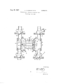
- the drawing is a cross-sectional view of a pneumatic double-acting diaphragm pump of this invention.
- the improved diaphragm pump of the present invention which comprises a casing having therein a partition dividing the interior of said casing into two separate compartments, a substantially vertically positioned flexible diaphragm spanning and dividing each of said compartments into inner and outer spaces, the former of which adjoin, while the latter are located remotely from, said partition, movable means interconnecting said diaphragms through said partition, fluid inlet and discharge ports positioned substantially from each other at the bottom and top, respectively, of each of said outer spaces and communicating therewith, ballcheck valves communicating with said outer spaces through each of said ports, an air control valve chamber formed in said partition, and an air-operated control valve located within said valve chamber and adapted to admit compressed air alternately to each of said inner spaces and simultaneously to vent compressed air to the atmosphere from the other of said inner spaces, thereby to flex said
- this invention provides an improved double-acting pneumatic diaphragm pump 10 which comprises a casing 11 of substantially circular cross-section (as seen at right angles to the drawing) which forms a chamber 12 having therein a cylindrical partition 13 dividing the interior of said casing into segregated right and left compartments 14 and 15, respectively; substantially vertically positioned, circular flexible diaphragms 17 and 18 spanning and dividing each of said diaphragms centrally through said partition; liquid inlet ports 24 and 25 and discharge ports 26 and 27 positioned substantially 180 from each other at the bottom and top, respectively, of each of said outer spaces 19 and 20 and communicating therewith; inlet ball-check valves 28 and 29 and discharge ball-check valves 30 and 31 communicating with said Outer space through each of said ports; a valve chamber 38 formed in said partition, an airoperated control valve 16 located within said valve chamber and adapted to admit compressed air alternately to each of said inner spaces and simultaneously to vent compressed air to atmosphere from the other of said inner spaces through an air-exhaus
- the flexible diaphragms of the pump are centrally interconnected by rigid movable means comprising connecting rod 23 and an inner and an outer metal clamping disk 47 and 50, respectively, which hold, at peripheral position, the inner edge of each of the centrally perforated flexible diaphragms.
- the outer disk has a smooth unbroken outer face and at least two symmetrically placed threaded blind studs 49 projecting at right angles from the opposite face of said outer disk, said studs mating with perforations in said inner disk and being attached thereto by nuts on said threaded studs.
- Each inner disk is also centrally attached to connecting rod 23 by a centrally located screw 46 held in place by a recessed set screw 48 entering said connecting rod at an angle of about 90 from the rods axis.
- closable access ports indicated at 44 and 45 permit access to each of said outer spaces of said pump chambers and to each of said ballcheck valve housings.
- a bleed-off valve 51 is provided for discharge of water from the inner spaces of the pump
- outer clamping disk 50 has a smooth outer surface and, therefore, there are no metal-to-metal surfaces in the space occupied by the liquid blasting agent.
- Compressed air used to operate the pump is supplied through an air filter to diagrammatically show air control valve 16 which is housed in a portion of the partition which also is provided with air inlet ports (not shown) communicating directly with the air control valve chamber 38 which in turn communicates with the inner space 21 and with inner space 22.
- the valve chamber 3 8 is also vented (passageways not shown) to the atmosphere through exhaust tube 43.
- material to be circulated is supplied to the pump through suction hoses attached to the inlet ports of ball-check valves 28 and 29.
- valve chamber 38 When air pressure is provided to valve chamber 38 and communicated by means of suitable passageways to the inner spaces 21 and 22, alternately, the diaphragms 17 and 18 joined by connecting rod 23, provided with suitable packing 42 and seals 33, are likewise simultaneously and alternately flexed outwardly and inwardly in' reciprocating motion, thus drawing the slurry through one inlet port into the outer space by suction and the reverse movement of the diaphragm closing the inlet valve and forcing the slurry through the upper passageway to a discharge port that may be provided with connecting pipes for conveying the slurry to a desired point.
- the diaphragms are shown in position at one end of a stroke of the connecting rod after the outer space of the right chamber has filled with slurry drawn through inlet port 24 and ballcheck valve 28, while the ball thereof was drawn up against stop 32.
- Air is admitted to inner space 21, then causing the diaphragm and plateassembly including outer disk 50 to displace liquid or slurry from outer space 19 out discharge port 26 and simultaneously sealing the ball of inlet valve 28.
- diaphragm 18 is flexed inwardly seating the ball of valve 31 and drawing fluid through inlet port 25 into outer space 20.
- Vacuum developed by the inward stroke of diaphragm 18 causes the ball of inlet valve 29 to be lifted from its seat 39 allowing fluid to flow into left space 20 and, of course, on reversal of the movement of diaphragm 18 the ball of inlet valve 29 is forced down and the ball of discharge valve 31 is forced from its seat allowing the liquid to be discharged through discharge port 27.
- the materials of construction are not specifically limiting or critical for the improved pump of the present invention.
- the pump casing, partition, valves, clamping disks, and connecting means therefore may be made of any conventional metal having adequate strength, but a stainless steel alloy, such as type 304 stainless steel, which is resistant to corrosion by said acidic slurry blasting agent or other corrosive liquid being pumped, is preferred for all parts of the pump which come in contact with said corrosive liquid.
- Centrally perforated diaphragms having molded heads at the inner and outer peripheries are illustrated in the drawing, but unperforated diaphragms may be used.
- the diaphragms generally are constructed of flexible and resilient polymeric materials reinforced by embedded fibrous materials or structures.
- Reinforced molded neoprene diaphragms are preferred in a pump of the present invention, but are not critical to the operation thereof.
- the material chosen for said diaphragms will be compatible with and will have long service life when in contact with the fluid being pumped.
- the halls in the check valves in a pump of the present invention preferably are made of neoprene.
- any long-lived resilient polymeric material may be used in place of neoprene.
- Ball-check valves having metalto-metal seals, of course, are not suitable from the safety standpoint when the fluid being pumped is an explosive or contains an explosive ingredient.
- Ball-check valves may be made of any compatible metal if nonexplosive, noncorrosive, and non-hazardous materials, for example food products, are being pumped.
- a pump of the present invention is intended particularly for pumping slurry blasting agents, said pump also is suitable in sanitary service by virtue of the freedom from obstructions in fluid flow channels, limited dispersive mechanical forces which are brought to bear on the fluid being pumped, and the ease of cleaning and of sterilization achieved by inclusion of clean out ports in the design, and use of corrosion-resisting materials in the construction of said pumps.
- a typical liquid blasting agent to be transferred by pumping has approximately the following composition:
- This blasting agent is viscous enough so that suspended solids such as grains of NaNO;,, TNT pellets, and granular aluminum powder do not readily settle out by gravity, but is fluid enough to be transferred by a diaphragm pump.
- the composition often contains gas bubbles entrapped during mixing or brought in with the ingredients.
- Example 1 A horizontal pneumatic diaphragm pump of the prior art having inlet and outlet ports positioned at the bottom of the outer space of each pump compartment and about 90 therefrom, respectively, is employed to pump blasting agent of the aforementioned composition. After about one hour of operation, the capacity of the pump is reduced fromabout 125 lbs. of composition per minute to about 80 pounds per minute. Disassembly of the pump shows an air bubble occupying approximately one-half the volume of the outer space of each pump chamber at maximum pressure developed during the discharge stroke. Elimination of the air bubble returns the capacity of the pump to its original value of about 125 pounds per minute. With continued use of the pump, an air bubble again gradually accumulates and again decreases the capacity of the pump, just as before.
- Example 2 A pumping test is made using only one pump compartment of the previously known design as described in Example 1 above. Air pressure is adjusted to give 64 strokes per minute. The pump delivers 95 pounds per minute of slurry-type blasting agent of the kind described hereinabove and having a temperature of 95 F.
- Example 3 A pump of the preferred design of this invention as illustrated in the drawing is operated with air under pressure of about 60 p.s.i.g. which produces about 78 strokes per minute and delivers about 4.85 pounds of liquid blasting agent (63 F.) per stroke against a discharge pressure of 14 p.s.i.g. At the end of 2-hours steady operation, the pump driven by 60 pounds air still delivers 78 strokes per minute and 4.80 pounds of liquid blasting agent (72 F.) per minute at a discharge pressure of 13 p.s.i.g. Removal of the covers of the access ports ShOWs that there is no accumulation of solids in the outer pump space or in the valve housings. Approximately only 10- minutes time is required to remove the cover from the access ports, make the inspection, and replace the covers. With intake and outlet port and valve arrangements of the prior art design, solids rapidly accumulate in the valve housing area and outer pump space and gradually block pump action.
- a pump comprising a casing having therein a partition dividing the interior of said casinginto two separate compartments, a substantially vertically positioned centrally perforated flexible diaphragm spanning and dividing each of said compartments into inner and outer spaces, the former of which adjoin, while the latter are located remotely from, said partition, said outer spaces being substantially free from internal obstructions, a valve located at the bottom of each of said inner spaces to permit substantially complete drainage of liquid therefrom, rigid movable means closing said central perforations and interconnecting said diaphragms through said partition, fluid inlet and discharge ports positioned substantially 180 from each other at the bottom and top, respectively, of each of said outer spaces and communicating therewith, ball-check valves communicating with said outer spaces through each of said ports said valves having no moving parts in metal-to-metal contact, an air control valve chamber formed in said partition, and an airoperated control valve located within said valve chamber and adapted to admit compressed air alternately to each of saidinner spaces and simultaneously to vent compressed air to atmosphere from the other of said
- a pump comprising a casing having therein a partition dividing the interior of said casing into two separate compartments, a substantially vertically positioned centrally perforated flexible diaphragm spanning and dividing each of said compartments into inner and outer spaces, the former of which adjoin, while the latter are located remotely from, said partition, a valve located at the bottom of each of said inner spaces to permit substantially complete drainage of liquid therefrom, rigid movable means closing said central perforations and interconnecting said diaphragms through said partition, fluid inlet and discharge ports positioned substantially 180 from each other at the bottom and top, respectively, of each of said outer spaces and communicating therewith, ballcheck valves communicating with said outer spaces through each of said ports, said valves having no moving parts in metal-to-metal contact, an air control valve chamber formed in said partition, and an air-operated control valve located within said valve chamber and adapted to admit compressed air alternately to each of said inner spaces and simultaneously to vent compressed air to atmosphere from the other of said inner spaces through an air-exhaust conduit, and
Description
Aug. 29. 1967 J. H. CONKLIN ETAL 3,338,171
PNEUMATICALLY OPERABLE DIAPHRAGM PUMPS Filed Sept. 15, 1965 IN VENTORS ATTOP FY United States Patent 3,338,171 PNEUMATICALLY OPERABLE DIAPHRAGM PUMPS James H. Conklin, Shepherdstown, W. Va., and Cecil G. Miller, Jr., Hagerstown, Md., assignors to E. I. du Pont de Nemours and Company, Wilmington, Del., a corporation of Delaware Filed Sept. 15, 1965, Ser. N 0. 487,463 2 Claims. (Cl. 103-152) This invention relates to pneumatically operable diaphragm pumps and, more particularly, to improved pneumatically operable diaphragm pumps which are especially suitable for pumping liquid blasting agents and liquids containing explosive ingredients.
Diaphragm pumps are well known for their utility in pumping thickened or solids-laden liquids as well as for pumping plain water, other liquids, and low-viscosity solutions based on such liquids. Accordingly, diaphragm pumps have found extensive use in pumping out sumps, shafts, and pits, and generally in handling a great variety of slurries, sludges, and waste-laden liquids. Pneumatically driven diaphragm pumps offer certain further advantages in convenience, effectiveness, portability, and safety, as disclosed in US. Patent No. 2,780,177. This patent describes a single-action type pump having two interconnected horizontally disposed diaphragms which operate with an up-and-down motion, and two pneumatically operated valve closures, one each on an intake line and a discharge line, respectively. In another modification of the above described pump, the cylindrical casing of the pump is mounted in a substantially horizontal position, diaphragms are disposed vertically, the connecting rod between them moves back and forth in a substantially horizontal direction, both diaphragms communicate with inktae and discharge ports, and the air-exhaust line vents to atmosphere through a gas-type muflier rather than through the space under a hood which covers the upper diaphragm, as in the vertical type pump. A diaphragm pump of this latter or horizontal modification is sometimes designated as the double-acting type.
In recent years certain kinds of blasting operations have been carried out by use of Water-bearing, slurry-type blasting agents which are pumped from bulk containers such as delivery trucks, or from portable mixing plants, directly into the boreholes. Large diameter boreholes of considerable depth can be loaded quickly, completely, and economically -by the use of pumped slurry-type blasting agents. Because such blasting agents usually are thickened and contain substantial amounts of more or less abrasive undissolved solids, a diaphragm pump is admirably suited for loading said slurry-type blasting agents into boreholes. Although said water-bearing, slurry-type blasting agents are relatively insensitive and require substantially stronger initiation than that furnished by a blasting cap, they often contain particles of undissolved high explosives as sensitizing agents. Hence, freedom from metal-to-metal contacts and potential friction and pinch points in pumps is desirable for maximum safety in pumping such explosive compositions. Further, obstructions such as partitions, bolt-heads, nuts, and the like within the pump spaces, through which the slurry explosive composition passes, provide localized areas of reduced flow velocity wherein suspended solids may be deposited and further interfere with operation of the ballcheck valves or with flow of said composition through the pump. If solids do accumulate or foreign materials become lodged in the ball-check valve housings or in the space between the diaphragm and the end of the pump casing, major dismantlement of the pump assembly will be required for cleaning. If the pump is included in a 3,338,171 Patented Aug. 29, 1967 semipermanent installation with more or less rigid piping, dismantlement of the pump becomes a very timeconsuming operation.
Pneumatically driven diaphragm pumps of the double acting or horizontal type are rugged and compact and, to gain maximum flexibility, often either are placed in the liquid being pumped or are served by a single intake line and deliver liquid through a short manifold to a single discharge line, usually a flexible tube or hose;
Experience shows that. such an arrangement of intake and discharge lines, and cooperating valves, often results in a relatively low pumping efliciency. That is, the volume of liquid delivered through the discharge line is appreciably less than would be expected on the basis of the cumulative volume change represented by movements of the flexible diaphragms in a given period of time. In addition to the relatively poor pumping efliciency, the churning of the fluid in the outer diaphragm spaces and the discharge manifold may result in disintegration of aggregates or pellets of suspended solids, especially explosive sensitizers in slurry blasting compositions. Another difiiculty is encountered in field use of said pneumatically driven pumps during freezing Weather. Compressed air supplies, unless especially dried, usually carry with them moisture which accumulates in the inner space of each diaphragm chamber, freezes when the surrounding temperature drops below about 32 F., and thereby renders the pump inoperative.
The features which comprise the improvements of the present invention and the manner of constructing and using diaphragm pumps containing these improvements will be apparent from the accompanying drawing and detailed description.
The drawing is a cross-sectional view of a pneumatic double-acting diaphragm pump of this invention.
The aforementioned difliculties encountered in use of the above-described double-acting pneumatic diaphragm pumps, especially when used for pumping fluid blasting agents, are overcome by the improved diaphragm pump of the present invention which comprises a casing having therein a partition dividing the interior of said casing into two separate compartments, a substantially vertically positioned flexible diaphragm spanning and dividing each of said compartments into inner and outer spaces, the former of which adjoin, while the latter are located remotely from, said partition, movable means interconnecting said diaphragms through said partition, fluid inlet and discharge ports positioned substantially from each other at the bottom and top, respectively, of each of said outer spaces and communicating therewith, ballcheck valves communicating with said outer spaces through each of said ports, an air control valve chamber formed in said partition, and an air-operated control valve located within said valve chamber and adapted to admit compressed air alternately to each of said inner spaces and simultaneously to vent compressed air to the atmosphere from the other of said inner spaces, thereby to flex said diaphragms simultanously in like directions.
Referring to the drawing in detail, this invention provides an improved double-acting pneumatic diaphragm pump 10 which comprises a casing 11 of substantially circular cross-section (as seen at right angles to the drawing) which forms a chamber 12 having therein a cylindrical partition 13 dividing the interior of said casing into segregated right and left compartments 14 and 15, respectively; substantially vertically positioned, circular flexible diaphragms 17 and 18 spanning and dividing each of said diaphragms centrally through said partition; liquid inlet ports 24 and 25 and discharge ports 26 and 27 positioned substantially 180 from each other at the bottom and top, respectively, of each of said outer spaces 19 and 20 and communicating therewith; inlet ball-check valves 28 and 29 and discharge ball-check valves 30 and 31 communicating with said Outer space through each of said ports; a valve chamber 38 formed in said partition, an airoperated control valve 16 located within said valve chamber and adapted to admit compressed air alternately to each of said inner spaces and simultaneously to vent compressed air to atmosphere from the other of said inner spaces through an air-exhaust conduit and thereby to flex said diaphragms simultaneously in like directions.
The flexible diaphragms of the pump are centrally interconnected by rigid movable means comprising connecting rod 23 and an inner and an outer metal clamping disk 47 and 50, respectively, which hold, at peripheral position, the inner edge of each of the centrally perforated flexible diaphragms. The outer disk has a smooth unbroken outer face and at least two symmetrically placed threaded blind studs 49 projecting at right angles from the opposite face of said outer disk, said studs mating with perforations in said inner disk and being attached thereto by nuts on said threaded studs. Each inner disk is also centrally attached to connecting rod 23 by a centrally located screw 46 held in place by a recessed set screw 48 entering said connecting rod at an angle of about 90 from the rods axis. Furthermore, closable access ports indicated at 44 and 45 permit access to each of said outer spaces of said pump chambers and to each of said ballcheck valve housings. A bleed-off valve 51 is provided for discharge of water from the inner spaces of the pump compartments.
With further reference to the figure, it will be apparent that all potential metal-to-metal surface contacts within said outer pump spaces which are in contact with explosive ingredients in said liquid blasting agent are eliminated by welding or by contact with resilient plastic or elastomeric materials. Such construction is preferred as a safety measure when handling explosive-containing fluids. The presence of boltheads in the outer spaces or process side, of the .pump compartments is undesirable when slurries containing explosive ingredients are pumped because the bolthead represents a potential metal-to-metal .pinch point which might initiate explosive collected under and about a loosened bolthead. In the improved pump of the present invention, as shown in the figure, outer clamping disk 50 has a smooth outer surface and, therefore, there are no metal-to-metal surfaces in the space occupied by the liquid blasting agent.
Compressed air used to operate the pump is supplied through an air filter to diagrammatically show air control valve 16 which is housed in a portion of the partition which also is provided with air inlet ports (not shown) communicating directly with the air control valve chamber 38 which in turn communicates with the inner space 21 and with inner space 22. The valve chamber 3 8 is also vented (passageways not shown) to the atmosphere through exhaust tube 43. Although various means are suitable for controlling the compressed air to effect movement of the diaphragms, the spool type valve described in US. Patent 2,780,177 has been found to be suitable.
In operation, material to be circulated is supplied to the pump through suction hoses attached to the inlet ports of ball-check valves 28 and 29. When air pressure is provided to valve chamber 38 and communicated by means of suitable passageways to the inner spaces 21 and 22, alternately, the diaphragms 17 and 18 joined by connecting rod 23, provided with suitable packing 42 and seals 33, are likewise simultaneously and alternately flexed outwardly and inwardly in' reciprocating motion, thus drawing the slurry through one inlet port into the outer space by suction and the reverse movement of the diaphragm closing the inlet valve and forcing the slurry through the upper passageway to a discharge port that may be provided with connecting pipes for conveying the slurry to a desired point. For example, in the figure the diaphragms are shown in position at one end of a stroke of the connecting rod after the outer space of the right chamber has filled with slurry drawn through inlet port 24 and ballcheck valve 28, while the ball thereof was drawn up against stop 32. Air is admitted to inner space 21, then causing the diaphragm and plateassembly including outer disk 50 to displace liquid or slurry from outer space 19 out discharge port 26 and simultaneously sealing the ball of inlet valve 28. At the same time, diaphragm 18 is flexed inwardly seating the ball of valve 31 and drawing fluid through inlet port 25 into outer space 20. Vacuum developed by the inward stroke of diaphragm 18 causes the ball of inlet valve 29 to be lifted from its seat 39 allowing fluid to flow into left space 20 and, of course, on reversal of the movement of diaphragm 18 the ball of inlet valve 29 is forced down and the ball of discharge valve 31 is forced from its seat allowing the liquid to be discharged through discharge port 27.
When the pneumatic pump of this invention is used to pump slurries, trapping of gas in the outer spaces 19 and 20, which reduces the effectiveness of known pneumatic pumps, is eliminated and pumping efliciency is improved because discharge ports 26 and 27 are located at the top of said outer spaces 19 and 20 of the pump compartments and substantially from inlet ports 24 and 25, thus providing a straightthrough, unimpeded flow of the fluid being pumped and permitting gases from whatever source to pass easily through the pump to a discharge line.
The materials of construction are not specifically limiting or critical for the improved pump of the present invention. The pump casing, partition, valves, clamping disks, and connecting means therefore may be made of any conventional metal having adequate strength, but a stainless steel alloy, such as type 304 stainless steel, which is resistant to corrosion by said acidic slurry blasting agent or other corrosive liquid being pumped, is preferred for all parts of the pump which come in contact with said corrosive liquid. Centrally perforated diaphragms having molded heads at the inner and outer peripheries are illustrated in the drawing, but unperforated diaphragms may be used. The diaphragms generally are constructed of flexible and resilient polymeric materials reinforced by embedded fibrous materials or structures. Reinforced molded neoprene diaphragms are preferred in a pump of the present invention, but are not critical to the operation thereof. In general, the material chosen for said diaphragms will be compatible with and will have long service life when in contact with the fluid being pumped.
The halls in the check valves in a pump of the present invention preferably are made of neoprene. However, any long-lived resilient polymeric material may be used in place of neoprene. Ball-check valves, having metalto-metal seals, of course, are not suitable from the safety standpoint when the fluid being pumped is an explosive or contains an explosive ingredient. Ball-check valves may be made of any compatible metal if nonexplosive, noncorrosive, and non-hazardous materials, for example food products, are being pumped. While a pump of the present invention is intended particularly for pumping slurry blasting agents, said pump also is suitable in sanitary service by virtue of the freedom from obstructions in fluid flow channels, limited dispersive mechanical forces which are brought to bear on the fluid being pumped, and the ease of cleaning and of sterilization achieved by inclusion of clean out ports in the design, and use of corrosion-resisting materials in the construction of said pumps.
Advantages gained by use of the improved pneumatic diaphragm pumps of the present invention will be more fully understood and appreciated by considering the following examples which, however, are not to be interpreted as limiting in any way the scope of the present invention.
In the following examples, a typical liquid blasting agent to be transferred by pumping has approximately the following composition:
Percent by weight This blasting agent is viscous enough so that suspended solids such as grains of NaNO;,, TNT pellets, and granular aluminum powder do not readily settle out by gravity, but is fluid enough to be transferred by a diaphragm pump. The composition often contains gas bubbles entrapped during mixing or brought in with the ingredients.
Example 1 A horizontal pneumatic diaphragm pump of the prior art having inlet and outlet ports positioned at the bottom of the outer space of each pump compartment and about 90 therefrom, respectively, is employed to pump blasting agent of the aforementioned composition. After about one hour of operation, the capacity of the pump is reduced fromabout 125 lbs. of composition per minute to about 80 pounds per minute. Disassembly of the pump shows an air bubble occupying approximately one-half the volume of the outer space of each pump chamber at maximum pressure developed during the discharge stroke. Elimination of the air bubble returns the capacity of the pump to its original value of about 125 pounds per minute. With continued use of the pump, an air bubble again gradually accumulates and again decreases the capacity of the pump, just as before. The relatively low flow of liquid through the pump also results in accumulation of compacted TNT aggregates on the seats of the ball-check valves so that the balls do not seat firmly and close the openings of the ball-check valve. These difficulties are not encountered in a pneumatic diaphragm pump of the present invention having inlet and outlet ports at the bottom and top of each outer space positioned substantially 180 from each other. The capacity of the pump of the invention remains uniform at about 125 pounds per minute throughout the test period.
Example 2 A pumping test is made using only one pump compartment of the previously known design as described in Example 1 above. Air pressure is adjusted to give 64 strokes per minute. The pump delivers 95 pounds per minute of slurry-type blasting agent of the kind described hereinabove and having a temperature of 95 F.
In comparison, a single pump compartment of the present invention wherein the inlet and discharge ports are at the bottom and top, respectively, of the outer space of the pump compartment is now used. The pumping test is repeated on the same lot of slurry blasting agent now at a temperature of 75 F. The air pressure is adjusted to give 50 strokes per minute. The pump delivers 232 pounds per minute of blasting agent, even in spite of the somewhat lower temperature at which the blasting agent is slightly more viscous and the lesser number of strokes per minute. The results of these comparative pumping tests illustrate the greatly increased capacity attained in a pump of the present invention as compared with a pneumatic diaphragm pump of the prior art.
Example 3 A pump of the preferred design of this invention as illustrated in the drawing is operated with air under pressure of about 60 p.s.i.g. which produces about 78 strokes per minute and delivers about 4.85 pounds of liquid blasting agent (63 F.) per stroke against a discharge pressure of 14 p.s.i.g. At the end of 2-hours steady operation, the pump driven by 60 pounds air still delivers 78 strokes per minute and 4.80 pounds of liquid blasting agent (72 F.) per minute at a discharge pressure of 13 p.s.i.g. Removal of the covers of the access ports ShOWs that there is no accumulation of solids in the outer pump space or in the valve housings. Approximately only 10- minutes time is required to remove the cover from the access ports, make the inspection, and replace the covers. With intake and outlet port and valve arrangements of the prior art design, solids rapidly accumulate in the valve housing area and outer pump space and gradually block pump action.
We claim:
1. A pump comprising a casing having therein a partition dividing the interior of said casinginto two separate compartments, a substantially vertically positioned centrally perforated flexible diaphragm spanning and dividing each of said compartments into inner and outer spaces, the former of which adjoin, while the latter are located remotely from, said partition, said outer spaces being substantially free from internal obstructions, a valve located at the bottom of each of said inner spaces to permit substantially complete drainage of liquid therefrom, rigid movable means closing said central perforations and interconnecting said diaphragms through said partition, fluid inlet and discharge ports positioned substantially 180 from each other at the bottom and top, respectively, of each of said outer spaces and communicating therewith, ball-check valves communicating with said outer spaces through each of said ports said valves having no moving parts in metal-to-metal contact, an air control valve chamber formed in said partition, and an airoperated control valve located within said valve chamber and adapted to admit compressed air alternately to each of saidinner spaces and simultaneously to vent compressed air to atmosphere from the other of said inner spaces through an air-exhaust conduit, and thereby to flex said diaphragms simultaneously in like directions.
2. A pump comprising a casing having therein a partition dividing the interior of said casing into two separate compartments, a substantially vertically positioned centrally perforated flexible diaphragm spanning and dividing each of said compartments into inner and outer spaces, the former of which adjoin, while the latter are located remotely from, said partition, a valve located at the bottom of each of said inner spaces to permit substantially complete drainage of liquid therefrom, rigid movable means closing said central perforations and interconnecting said diaphragms through said partition, fluid inlet and discharge ports positioned substantially 180 from each other at the bottom and top, respectively, of each of said outer spaces and communicating therewith, ballcheck valves communicating with said outer spaces through each of said ports, said valves having no moving parts in metal-to-metal contact, an air control valve chamber formed in said partition, and an air-operated control valve located within said valve chamber and adapted to admit compressed air alternately to each of said inner spaces and simultaneously to vent compressed air to atmosphere from the other of said inner spaces through an air-exhaust conduit, and thereby to flex said diaphragms simultaneously in like directions, wherein the central perforation of each of said flexible diaphragms is closed by inner and outer metal clamping disks holding between them at a perpheral position the inner edge of said perforated flexible diaphragm, said outer disk having a smooth unbroken outer face and at least two symmetrically placed threaded blind studs projecting at right angles from the opposite face of said outer disk, said studs mating with perforations in said inner disk and being attached thereto by said threaded studs, each of said inner disks being attached to a rigid and movable connecting rod by a centrally located countersunk head screw held in References Cited UNITED STATES PATENTS 10/1901 Rayner 103152 7/1913 Lane 103152 8 Browne '103 152 X Fischer et a1 103 -1 -52 X Hoene-cke 103150 Hall 103152 Hanson et a1 103150 X ROBERT M. WALKER, Primary Examiner.
Claims (1)
1. A PUMP COMPRISING A CASING HAVING THEREIN A PARTTION DIVIDING THE INTERIOR OF SAID CASING INTO TWO SEPARATE COMPARTMENTS, A SUBSTANTIALLY VERTICALLY POSITIONED CENTRALLY PERFORATED FLEXIBLE DIAPHRAGM SPANNING AND DIVIDING EACH OF SAID COMPARTMENTS INTO INNER AND OUTER SPACES, THE FORMER OF WHICH ADJOIN, WHILE THE LATTER ARE LOCATED REMOTELY FROM, SAID PARTITION, SAID OUTER SPACES BEING SUBSTANTIALLY FREE FROM INTERNAL OBSTRUCTION, A VALVE LOCATED AT THE BOTTOM OF EACH OF SAID INNER SPACES TO PERMIT SUBSTANTIALLY COMPLETE DRAINAGE OF LIQUID THEREFROM, RIGID MOVABLE MEANS CLOSING SAID CENTRAL PERFORATIONS AND INTERCONNECTING SAID DIAPHRAGMS THROUGH SAID PARTITION, FLUID INLET AND DISCHARGE PORTS POSITIONED SUBSTANTIALLY 180* FROM EACH OTHER AT THE BOTTOM AND TOP, RESPECTIVELY, OF EACH OF SAID OUTER SPACES AND COMMUNICATING THEREWITH, BALL-CHECK VALVES COMMUNICATING WITH SAID OUTER SPACES THROUGH EACH OF SAID PORTS SAID VALVES HAVING NO MOVING PARTS IN METAL-TO-METAL CONTACT, AN AIR CONTROL VALVE CHAMBER FORMED IN SAID PARTITION, AND AN AIROPERATED CONTROL VALVE LOCATED WITHIN SAID VALVE CHAMBER AND ADAPTED TO ADMIT COMPRESSED AIR ALTERNATELY TO EACH OF SAID INNER SPACED AND SIMULTANEOUSLY TO VENT COMPRESSED AIR TO ATMOSPHERE FROM THE OTHER OF SAID INNER SPACED THROUGH AN AIR-EXHAUST CONDUIT, AND THEREBY TO FLEX SAID DIAPHRAGMS SIMULTANEOUSLY IN LIKE DIRECTIONS.
Priority Applications (1)
| Application Number | Priority Date | Filing Date | Title |
|---|---|---|---|
| US487463A US3338171A (en) | 1965-09-15 | 1965-09-15 | Pneumatically operable diaphragm pumps |
Applications Claiming Priority (1)
| Application Number | Priority Date | Filing Date | Title |
|---|---|---|---|
| US487463A US3338171A (en) | 1965-09-15 | 1965-09-15 | Pneumatically operable diaphragm pumps |
Publications (1)
| Publication Number | Publication Date |
|---|---|
| US3338171A true US3338171A (en) | 1967-08-29 |
Family
ID=23935816
Family Applications (1)
| Application Number | Title | Priority Date | Filing Date |
|---|---|---|---|
| US487463A Expired - Lifetime US3338171A (en) | 1965-09-15 | 1965-09-15 | Pneumatically operable diaphragm pumps |
Country Status (1)
| Country | Link |
|---|---|
| US (1) | US3338171A (en) |
Cited By (27)
| Publication number | Priority date | Publication date | Assignee | Title |
|---|---|---|---|---|
| US3429274A (en) * | 1966-06-08 | 1969-02-25 | Akerlund & Rausing Ab | Diaphragm pump,in particular for pumping viscous liquids |
| US3744937A (en) * | 1969-04-21 | 1973-07-10 | Dart Union Co | Diaphragm pump |
| JPS5437182B1 (en) * | 1970-12-28 | 1979-11-13 | ||
| WO1983001658A1 (en) * | 1981-11-04 | 1983-05-11 | Gosschalk, Terry | Pulse driven hydraulic pump |
| EP0125467A1 (en) * | 1983-04-20 | 1984-11-21 | William R. Selwood Limited | Diaphragm pump |
| US4634350A (en) * | 1981-11-12 | 1987-01-06 | The Coca-Cola Company | Double acting diaphragm pump and reversing mechanism therefor |
| US4705461A (en) * | 1979-09-19 | 1987-11-10 | Seeger Corporation | Two-component metering pump |
| US4708827A (en) * | 1986-03-17 | 1987-11-24 | The Cornelius Company | Method of and apparatus for making and dispensing carbonated water with a double diaphragm pneumatic water pump |
| US4778356A (en) * | 1985-06-11 | 1988-10-18 | Hicks Cecil T | Diaphragm pump |
| US4867654A (en) * | 1988-01-05 | 1989-09-19 | American Thermal Corporation | Fluid-driven pump |
| US4928683A (en) * | 1987-02-17 | 1990-05-29 | Bart Westerkamp | Respirating apparatus for patients |
| US6464474B2 (en) * | 2000-03-16 | 2002-10-15 | Lewa Herbert Ott Gmbh + Co. | Nonrespiratory diaphragm chucking |
| US20070140873A1 (en) * | 2004-03-18 | 2007-06-21 | Precision Dispensing Systems Limited | Pump |
| US20080296224A1 (en) * | 2007-05-29 | 2008-12-04 | Pumptec, Inc. | Reverse osmosis pump system |
| US20090068034A1 (en) * | 2007-09-12 | 2009-03-12 | Pumptec, Inc. | Pumping system with precise ratio output |
| US20100104458A1 (en) * | 2004-03-18 | 2010-04-29 | Precision Dispensing Systems Limited | pump |
| US20100111714A1 (en) * | 2008-10-30 | 2010-05-06 | Burden Timothy L | Diaphragm pumps and transporting drag reducers |
| US20120275943A1 (en) * | 2009-09-03 | 2012-11-01 | James Coates | Pump |
| US20160032919A1 (en) * | 2014-08-01 | 2016-02-04 | Murzan, Inc. | Fully-draining diaphragm pump and check valve assembly |
| US10167863B1 (en) | 2012-03-28 | 2019-01-01 | Pumptec, Inc. | Proportioning pump, control systems and applicator apparatus |
| US10760557B1 (en) | 2016-05-06 | 2020-09-01 | Pumptec, Inc. | High efficiency, high pressure pump suitable for remote installations and solar power sources |
| US10823160B1 (en) | 2017-01-12 | 2020-11-03 | Pumptec Inc. | Compact pump with reduced vibration and reduced thermal degradation |
| WO2022243793A1 (en) * | 2021-05-20 | 2022-11-24 | Precision Planting Llc | Double diaphragm slurry pump |
| US11571499B2 (en) | 2015-12-30 | 2023-02-07 | Quanta Dialysis Technologies Ltd. | Dialysis machine |
| US11583618B2 (en) | 2014-06-02 | 2023-02-21 | Quanta Dialysis Technologies Limited | Method of heat sanitization of a haemodialysis water circuit using a calculated dose |
| US11660382B2 (en) | 2016-12-23 | 2023-05-30 | Quanta Dialysis Technologies Limited | Valve leak detection system |
| USRE49881E1 (en) | 2013-03-28 | 2024-03-26 | Quanta Fluid Solutions Ltd. | Re-use of a hemodialysis cartridge |
Citations (7)
| Publication number | Priority date | Publication date | Assignee | Title |
|---|---|---|---|---|
| US684379A (en) * | 1901-01-25 | 1901-10-08 | Kerns Ag | Steam vacuum-pump. |
| US1067613A (en) * | 1912-07-06 | 1913-07-15 | George S Lane | Pneumatic pump. |
| US2625886A (en) * | 1947-08-21 | 1953-01-20 | American Brake Shoe Co | Pump |
| US2679209A (en) * | 1949-09-01 | 1954-05-25 | Arthur Bachert | Pumping apparatus |
| US2780177A (en) * | 1952-09-29 | 1957-02-05 | Walter J Hoenecke | Pneumatically operated diaphragm pump |
| US2798440A (en) * | 1954-02-26 | 1957-07-09 | Ernest A Hall | Fuel feed pump |
| US3092029A (en) * | 1961-09-05 | 1963-06-04 | Vendo Co | Fluid pumping mechanism |
-
1965
- 1965-09-15 US US487463A patent/US3338171A/en not_active Expired - Lifetime
Patent Citations (7)
| Publication number | Priority date | Publication date | Assignee | Title |
|---|---|---|---|---|
| US684379A (en) * | 1901-01-25 | 1901-10-08 | Kerns Ag | Steam vacuum-pump. |
| US1067613A (en) * | 1912-07-06 | 1913-07-15 | George S Lane | Pneumatic pump. |
| US2625886A (en) * | 1947-08-21 | 1953-01-20 | American Brake Shoe Co | Pump |
| US2679209A (en) * | 1949-09-01 | 1954-05-25 | Arthur Bachert | Pumping apparatus |
| US2780177A (en) * | 1952-09-29 | 1957-02-05 | Walter J Hoenecke | Pneumatically operated diaphragm pump |
| US2798440A (en) * | 1954-02-26 | 1957-07-09 | Ernest A Hall | Fuel feed pump |
| US3092029A (en) * | 1961-09-05 | 1963-06-04 | Vendo Co | Fluid pumping mechanism |
Cited By (34)
| Publication number | Priority date | Publication date | Assignee | Title |
|---|---|---|---|---|
| US3429274A (en) * | 1966-06-08 | 1969-02-25 | Akerlund & Rausing Ab | Diaphragm pump,in particular for pumping viscous liquids |
| US3744937A (en) * | 1969-04-21 | 1973-07-10 | Dart Union Co | Diaphragm pump |
| JPS5437182B1 (en) * | 1970-12-28 | 1979-11-13 | ||
| US4705461A (en) * | 1979-09-19 | 1987-11-10 | Seeger Corporation | Two-component metering pump |
| WO1983001658A1 (en) * | 1981-11-04 | 1983-05-11 | Gosschalk, Terry | Pulse driven hydraulic pump |
| US4634350A (en) * | 1981-11-12 | 1987-01-06 | The Coca-Cola Company | Double acting diaphragm pump and reversing mechanism therefor |
| EP0125467A1 (en) * | 1983-04-20 | 1984-11-21 | William R. Selwood Limited | Diaphragm pump |
| US4778356A (en) * | 1985-06-11 | 1988-10-18 | Hicks Cecil T | Diaphragm pump |
| US4708827A (en) * | 1986-03-17 | 1987-11-24 | The Cornelius Company | Method of and apparatus for making and dispensing carbonated water with a double diaphragm pneumatic water pump |
| US4928683A (en) * | 1987-02-17 | 1990-05-29 | Bart Westerkamp | Respirating apparatus for patients |
| US4867654A (en) * | 1988-01-05 | 1989-09-19 | American Thermal Corporation | Fluid-driven pump |
| US6464474B2 (en) * | 2000-03-16 | 2002-10-15 | Lewa Herbert Ott Gmbh + Co. | Nonrespiratory diaphragm chucking |
| US8454324B2 (en) * | 2004-03-18 | 2013-06-04 | Precision Dispensing Systems Limited | Pump |
| US20070140873A1 (en) * | 2004-03-18 | 2007-06-21 | Precision Dispensing Systems Limited | Pump |
| US20100104458A1 (en) * | 2004-03-18 | 2010-04-29 | Precision Dispensing Systems Limited | pump |
| US20080296224A1 (en) * | 2007-05-29 | 2008-12-04 | Pumptec, Inc. | Reverse osmosis pump system |
| US20090068034A1 (en) * | 2007-09-12 | 2009-03-12 | Pumptec, Inc. | Pumping system with precise ratio output |
| US20100111714A1 (en) * | 2008-10-30 | 2010-05-06 | Burden Timothy L | Diaphragm pumps and transporting drag reducers |
| US8215930B2 (en) | 2008-10-30 | 2012-07-10 | Phillips 66 Company | Diaphragm pumps and transporting drag reducers |
| US20120275943A1 (en) * | 2009-09-03 | 2012-11-01 | James Coates | Pump |
| US9482218B2 (en) * | 2009-09-03 | 2016-11-01 | Quanta Fluid Solutions Ltd. | Deformable membrane pump for dialysis machine |
| US10167863B1 (en) | 2012-03-28 | 2019-01-01 | Pumptec, Inc. | Proportioning pump, control systems and applicator apparatus |
| US10724515B1 (en) * | 2012-03-28 | 2020-07-28 | Pumptec, Inc. | Proportioning pump, control systems and applicator apparatus |
| USRE49881E1 (en) | 2013-03-28 | 2024-03-26 | Quanta Fluid Solutions Ltd. | Re-use of a hemodialysis cartridge |
| US11583618B2 (en) | 2014-06-02 | 2023-02-21 | Quanta Dialysis Technologies Limited | Method of heat sanitization of a haemodialysis water circuit using a calculated dose |
| US20160032919A1 (en) * | 2014-08-01 | 2016-02-04 | Murzan, Inc. | Fully-draining diaphragm pump and check valve assembly |
| WO2016019229A1 (en) * | 2014-08-01 | 2016-02-04 | Alberto Bazan | Fully-draining diaphragm pump and check valve assembly |
| US10006456B2 (en) * | 2014-08-01 | 2018-06-26 | Murzan, Inc. | Fully-draining diaphragm pump and check valve assembly |
| US11028846B2 (en) | 2014-08-01 | 2021-06-08 | Murzan, Inc. | Fully-draining diaphragm pump and check valve assembly |
| US11571499B2 (en) | 2015-12-30 | 2023-02-07 | Quanta Dialysis Technologies Ltd. | Dialysis machine |
| US10760557B1 (en) | 2016-05-06 | 2020-09-01 | Pumptec, Inc. | High efficiency, high pressure pump suitable for remote installations and solar power sources |
| US11660382B2 (en) | 2016-12-23 | 2023-05-30 | Quanta Dialysis Technologies Limited | Valve leak detection system |
| US10823160B1 (en) | 2017-01-12 | 2020-11-03 | Pumptec Inc. | Compact pump with reduced vibration and reduced thermal degradation |
| WO2022243793A1 (en) * | 2021-05-20 | 2022-11-24 | Precision Planting Llc | Double diaphragm slurry pump |
Similar Documents
| Publication | Publication Date | Title |
|---|---|---|
| US3338171A (en) | Pneumatically operable diaphragm pumps | |
| AU612698B2 (en) | Pump and valve apparatus | |
| CA2990026C (en) | Fluid liner wear indicator for suction manifold of reciprocating pump assembly | |
| US5094596A (en) | High pressure piston pump for fluent materials | |
| US3330217A (en) | Pump | |
| US3630642A (en) | Diaphragm pump | |
| US3161591A (en) | Filtering apparatus for liquid materials | |
| US2764097A (en) | Pump | |
| US2444586A (en) | Pump | |
| US3664770A (en) | Diaphragm pumps | |
| US2810347A (en) | Fluid pump | |
| CN103140679A (en) | Double-membrane central-flow pump | |
| US5334001A (en) | Mounting arrangement for a positive displacement slurry pump | |
| US4623303A (en) | Pump for slurries | |
| JPS6210485A (en) | Improvement in pump | |
| US4397614A (en) | Unbalanced spool | |
| US2609756A (en) | Reciprocating pump | |
| CN209012056U (en) | A kind of water-ring vacuum pump | |
| US4385874A (en) | Rotary pump apparatus with plural abutting pumping segments | |
| CN202746157U (en) | Controllable type pneumatic double diaphragm pump | |
| CN102410182B (en) | Controllable pneumatic double diaphragm pump | |
| CN206377308U (en) | The membrane pump of a kind of check-valves including the check-valves and the filter press including the membrane pump | |
| US3135219A (en) | Pumping apparatus | |
| JPH1163268A (en) | Aerator valve assembly for pneumatic device | |
| US783990A (en) | Pump. |