US3177828A - Planter hitch frame assembly - Google Patents
Planter hitch frame assembly Download PDFInfo
- Publication number
- US3177828A US3177828A US831901A US83190159A US3177828A US 3177828 A US3177828 A US 3177828A US 831901 A US831901 A US 831901A US 83190159 A US83190159 A US 83190159A US 3177828 A US3177828 A US 3177828A
- Authority
- US
- United States
- Prior art keywords
- implement frame
- tongue
- planting
- planter
- implement
- Prior art date
- Legal status (The legal status is an assumption and is not a legal conclusion. Google has not performed a legal analysis and makes no representation as to the accuracy of the status listed.)
- Expired - Lifetime
Links
- 230000008878 coupling Effects 0.000 claims description 14
- 238000010168 coupling process Methods 0.000 claims description 14
- 238000005859 coupling reaction Methods 0.000 claims description 14
- 239000002689 soil Substances 0.000 claims description 6
- 210000002105 tongue Anatomy 0.000 description 32
- 238000000034 method Methods 0.000 description 13
- 241000196324 Embryophyta Species 0.000 description 6
- 230000008569 process Effects 0.000 description 6
- 241001236644 Lavinia Species 0.000 description 3
- 230000003111 delayed effect Effects 0.000 description 3
- 239000003550 marker Substances 0.000 description 3
- 230000004048 modification Effects 0.000 description 3
- 238000012986 modification Methods 0.000 description 3
- 230000009467 reduction Effects 0.000 description 3
- 230000008901 benefit Effects 0.000 description 2
- 229910000831 Steel Inorganic materials 0.000 description 1
- 240000008042 Zea mays Species 0.000 description 1
- 235000005824 Zea mays ssp. parviglumis Nutrition 0.000 description 1
- 235000002017 Zea mays subsp mays Nutrition 0.000 description 1
- 230000002411 adverse Effects 0.000 description 1
- 238000010276 construction Methods 0.000 description 1
- 235000005822 corn Nutrition 0.000 description 1
- 230000000694 effects Effects 0.000 description 1
- 239000000945 filler Substances 0.000 description 1
- 238000003197 gene knockdown Methods 0.000 description 1
- 239000000463 material Substances 0.000 description 1
- 230000007246 mechanism Effects 0.000 description 1
- 238000010899 nucleation Methods 0.000 description 1
- 238000012856 packing Methods 0.000 description 1
- 239000010908 plant waste Substances 0.000 description 1
- 238000002360 preparation method Methods 0.000 description 1
- 230000003014 reinforcing effect Effects 0.000 description 1
- 239000010959 steel Substances 0.000 description 1
Images
Classifications
-
- A—HUMAN NECESSITIES
- A01—AGRICULTURE; FORESTRY; ANIMAL HUSBANDRY; HUNTING; TRAPPING; FISHING
- A01C—PLANTING; SOWING; FERTILISING
- A01C15/00—Fertiliser distributors
- A01C15/005—Undercarriages, tanks, hoppers, stirrers specially adapted for seeders or fertiliser distributors
-
- A—HUMAN NECESSITIES
- A01—AGRICULTURE; FORESTRY; ANIMAL HUSBANDRY; HUNTING; TRAPPING; FISHING
- A01B—SOIL WORKING IN AGRICULTURE OR FORESTRY; PARTS, DETAILS, OR ACCESSORIES OF AGRICULTURAL MACHINES OR IMPLEMENTS, IN GENERAL
- A01B49/00—Combined machines
- A01B49/04—Combinations of soil-working tools with non-soil-working tools, e.g. planting tools
-
- A—HUMAN NECESSITIES
- A01—AGRICULTURE; FORESTRY; ANIMAL HUSBANDRY; HUNTING; TRAPPING; FISHING
- A01B—SOIL WORKING IN AGRICULTURE OR FORESTRY; PARTS, DETAILS, OR ACCESSORIES OF AGRICULTURAL MACHINES OR IMPLEMENTS, IN GENERAL
- A01B51/00—Undercarriages specially adapted for mounting-on various kinds of agricultural tools or apparatus
- A01B51/04—Undercarriages specially adapted for mounting-on various kinds of agricultural tools or apparatus drawn by animal or tractor
-
- Y—GENERAL TAGGING OF NEW TECHNOLOGICAL DEVELOPMENTS; GENERAL TAGGING OF CROSS-SECTIONAL TECHNOLOGIES SPANNING OVER SEVERAL SECTIONS OF THE IPC; TECHNICAL SUBJECTS COVERED BY FORMER USPC CROSS-REFERENCE ART COLLECTIONS [XRACs] AND DIGESTS
- Y10—TECHNICAL SUBJECTS COVERED BY FORMER USPC
- Y10S—TECHNICAL SUBJECTS COVERED BY FORMER USPC CROSS-REFERENCE ART COLLECTIONS [XRACs] AND DIGESTS
- Y10S111/00—Planting
- Y10S111/924—Minimum and no till planter
Definitions
- This invention relates to the trailing of equipment and at the present time appears to have its greatest application in the trailing of seed planters although it is by no means limited thereto.
- the common practice is to traverse the field at least twice with a tractor pulling a disk harrow (commonly known as a disk) and to then go over the field a third time with the tractor pulling a rigid toothed implement'called a drag harrow or drag.
- my invention could be used to break up the previous crop residue, plow, double disk, drag and plant all in one traversing of the field; however, since it is commonly accepted to be desirable that the plowing be done some time ahead of planting on certain types of ground in order that the clods and chunks may have an opportunity to weather, I have herein illustrated my invention as performing only the double disking, dragging and planting operations simultaneously, these being almost universally accepted as following one another'in quick succession.
- Another object of this invention is to provide a method and a means which enable a material reduction in the number of trips across a field which are required in order to complete the operation of planting.
- a further object of this invention is to teach a method of planting seed which enables preparation of the seed bed together with controlled and accurate planting of the seed during a single traversing of the field.
- Yet another object of this invention is to provide means for executing said latter method.
- a still further object of this invention is to teach a method of trailing or towing a'plurality of implements or items of equipment behind a guidable vehicle in which some items are disposed approximately behind others but in which the position and path of travel of therearmost implementis directly controlled by the movement of said guidable vehicle.
- An additional object of this invention ' is to provide means for hitching to a guidable vehicle "an implement which is spaced from said guidable vehicle by other equipment.
- my invention comprises the process of trailing a planter behind implements for readying the ground for planting, said latter implements being towed by a farm tractor to which the planter is also directly or substantially directly attached.
- my planting process I prefer to employ a relatively long tongue member which attaches at one of its ends to the planter and at its other end to" the tractor draw-bar or to a point adjacent the same, the central section of the said tongue being offset upwardly to avoid interference with the ground readying implements disposed between the said tractor and planter.
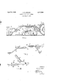
- FIGURE 1' is a side elevation of an assembly of implements arranged to embody and illustrate my invention, the elongated tongue which I have mentioned above being shown in operative position.
- FIGURE II is a side elevation of the detached tongue assembly, the same being shown enlarged.
- FIGURE III is a side elevation of the tractor end of the tongue together with adjacent parts, illustrating a "designated generally by the reference character 21.
- the tongue 21 may well be formed from an elongated steel tube. In the embodiment shown pin 48.
- a Z member 31 has been attached to the top portion of the tongue 13 of the disk 14 and a pin 32 has been installed in suitable orifices in said 2 member 31' and tongue 13, passing also through the orifice in plate 29.
- a horizontal bar 33 and angling bars 34 and 35 have been provided on each side of the central horizontal section 25 .
- a pipe or conduit 36 has been attached, the one on the remote side being obscured in the drawing by the one on the side facing the viewer.
- each coupling member 37 has been secured adapted to cooperate with the coupling members 38 of the hoses 3-9 of the tractor hydraulic system and with the coupling members 40 of the hoses 41 of the hydraulic system of the planter 29 to provide the same hydraulic control of planter operations as is had when my invention is not in use.
- an extension arm 42supported by brace 43 has been provided to mount lever 44 which is operatively connected to the marker controls of the planter by wire or light chain 45.
- the pivot 46 of lever 44 is preferably of the friction type so that the lever 44 will remain in the position selected until again moved by the tractor operator. 7
- FIGURE III the front end of tongue 21 is hitched .directly to the drawbar of the tractor rather than to a member disposed adjacent thereto as in FIGURES I and II.
- reference character 47 has been used to designate the tractor drawbar to which plate 29 of tongue 21 is attached by hitch
- An otfset member 49 has been attached to' the under side of a drawbar47 to cooper-ate with the outer end of said drawbar and with hitch pin 50 to attach tongue 51 of the disk to the tractor.
- the offset tongue disclosed herein constitutes a highly effective means adapted to assist in carrying out my process, it is by no meansthe only generaltype of assembly which 'may be used.
- the tongue member if one is used, may be permanently attached to 'the tractor or to the planter, or to their respective replacementsgin fact the forward end could be attached to the tractor and the rearward end to the planter and the two segments hitched together at their free ends.
- a tongue of the general type shown it is not essential that the connection to the planter be of the relatively rigid type and/or that the connection to the tractor be of the swivel type. Further the offset in the tongue could be downward or sideways rather than up or it could be.
- a plurality of tongues could be offset one above another and a single, vertical, elongated hitch pin'at the guidable vehicle could receive the front hitches of all of the several said tongues, the construction being such that each said front hitch can turn on said pin relative to the other said. front hitches.
- a combination forpreparing a seed bed and simultaneously planting the same comprising a guidable prime mover, afirst implement frame, a soil working tool on said first implement frame, a tongue on said implement frameextending forwardly of said tool, coupling means on the forward portion of saidtongue for horizontally pivotally interconnecting thefirst implement frame to the prime mover, a second implement frame disposed behind the first implement frame, a seed planter on said second tion to said coupling means and said second implement frame is free to sway laterally in trailing relation to said hitch means.
- a combination for preparing a seed bed and simultaneously planting the same comprising a guidable prime mover, a first implement frame, a soil working tool on said first implement frame, a single coupling means for horizontally pivotally interconnecting the first implement frame to the prirne mover, draft member on the first implement frame extending forwardly'therefrom and operatively connecting said coupling means to said first implement frame, a second implement frame disposed behind the first implement frame, a seed planter on said second implement frame, hitch means on the draft member disposed between the coupling means and the soil working tool, and an elongated tongue attached at one of its ends to said second implement frame and having its other end horizontally pivotally attached to said hitch means whereby said first implement frame is free to sway laterally in trailing relation to said coupling means and said second implement frame is free to sway laterally in trailing relation to said hitch means.
- a combination for preparing a seed bed and simultaneously planting the same comprising a first implement frame, a soil Working tool on said first implement frame, a tongue on said implement frame extending forwardly of said tool, coupling means on the forward portion of said tongue for horizontally pivotally interconnecting the first implement frame to a guidable vehicle, a second implement frame disposed behind the first implement frame, a seed planter on said second implement frame, hitch means on said tongue between the coupling means and in trailing relation to said hitch means.
Description
April 13, 1965 D. R. CRAMER 3,177,828
PLANTER HITCH FRAME ASSEMBLY Filed Aug. 5, 1959 INVENTOR DON R. CRAMER ATTORNEY United States Patent O 3,177,828 PLANTER HITCH FRAME ASSEMBLY Don R. Cramer, Clarion, Iowa, assignor of one-third to Ray V. Bailey, Clarion, Iowa Filed Aug. 5, 1959, Ser. No. 831,901 6 Claims. (Cl. 111- -52) This invention relates to the trailing of equipment and at the present time appears to have its greatest application in the trailing of seed planters although it is by no means limited thereto.
When preparing a field for the planting of seed such as corn, it is the usual practice to first traverse the field with an implement adapted to knock down and break up the residue of the preceding crop after which the field is plowed with a plow of the moldboard type to turn up soil which has been beneath the surface. The normal result of the latter operation is a relatively exceedingly rough field surface due to the fact that much of the upturned ground is in the form of large clods and chunks. These clods and chunks are, of course, wholly unadapted to the planting of any seed and must be broken up into small, friable bits before the planting operation can proceed. To accomplish this end the common practice is to traverse the field at least twice with a tractor pulling a disk harrow (commonly known as a disk) and to then go over the field a third time with the tractor pulling a rigid toothed implement'called a drag harrow or drag. These operations having been completed, the field is ready for planting which, of course, entails traversing the field a fourth time with a tractor, this time pulling the'planter. Should it happen, as is often the case, that it rains between the time that the dragging is completed and the time it is possible to start planting, one or more additional coverages of the field will usually be required with a tractor pulling a disk or a drag. In fact it is not at all uncommon for planting to be delayed beyond the ideal planting season due to repeated rains, each coming while an attempt is being made to again ready the field for planting or after it has been again so readied but before the planting operation could be completed.
The disadvantages of the historical routine are several. For one thing it is expensive to drive a tractor over a field so many times not only from the standpoint of the quantities of gasoline and oil consumed but also from the standpoint of the wear and tear on the tractor itself which takes a terrific shaking each time it crosses a rough field. Further there is the matter of the cost of the manpower required to drive the tractor. Aside from the cost factor, the mere traversing of the ground so many times with the tractor has a tendency to pack it and to have an adverse effect on crop yields and, as previously inferred, the time consumed also often results in reduction in yield due to the planting operation having been delayed beyond the ideal period for planting.
The foregoing disadvantages are eliminated by my invention since the mechanism and process which I teach enable the double disking, dragging and planting to all be accomplished by a single coverage of the field. Thus, when a day arrives that is suitable for doing field work, I can go out and plant that day rather than being required to spend that day and several others just getting the field ready to plant. As a matter of fact my invention could be used to break up the previous crop residue, plow, double disk, drag and plant all in one traversing of the field; however, since it is commonly accepted to be desirable that the plowing be done some time ahead of planting on certain types of ground in order that the clods and chunks may have an opportunity to weather, I have herein illustrated my invention as performing only the double disking, dragging and planting operations simultaneously, these being almost universally accepted as following one another'in quick succession.
The idea of performing several field operations during one coverage of the field is not new but in the past in has not been possible to satisfactorily plant by trailing the planter behind other implements because it has not been possible to adequately control its movement and the locations of the hills of seed have accordingly beentoo uneven.
- It is an object of this invention to provide a method of planting which minimizes the likelihood of the planting operation being unduly delayed by weather conditions.
Another object of this invention is to provide a method and a means which enable a material reduction in the number of trips across a field which are required in order to complete the operation of planting.
A further object of this invention is to teach a method of planting seed which enables preparation of the seed bed together with controlled and accurate planting of the seed during a single traversing of the field.
7 Yet another object of this invention is to provide means for executing said latter method.
A still further object of this invention is to teach a method of trailing or towing a'plurality of implements or items of equipment behind a guidable vehicle in which some items are disposed approximately behind others but in which the position and path of travel of therearmost implementis directly controlled by the movement of said guidable vehicle. a v
An additional object of this invention 'is to provide means for hitching to a guidable vehicle "an implement which is spaced from said guidable vehicle by other equipment.
' Other objects of this invention will appear as the present disclosure proceeds.
Basically, in its preferred form, my invention comprises the process of trailing a planter behind implements for readying the ground for planting, said latter implements being towed by a farm tractor to which the planter is also directly or substantially directly attached. In executing my planting process, I prefer to employ a relatively long tongue member which attaches at one of its ends to the planter and at its other end to" the tractor draw-bar or to a point adjacent the same, the central section of the said tongue being offset upwardly to avoid interference with the ground readying implements disposed between the said tractor and planter.
In order that a clearer understanding of my invention may be had, reference is made to the accompanying drawings which form apart of this specification and in which: FIGURE 1' is a side elevation of an assembly of implements arranged to embody and illustrate my invention, the elongated tongue which I have mentioned above being shown in operative position. a
FIGURE II is a side elevation of the detached tongue assembly, the same being shown enlarged.
FIGURE III is a side elevation of the tractor end of the tongue together with adjacent parts, illustrating a "designated generally by the reference character 21.
I have found that the tongue 21 may well be formed from an elongated steel tube. In the embodiment shown pin 48.
the position of said guided vehicle. mover in a tow train is normally the vehicle which is also 3 in the drawing, the said tube has been bent to provide downwardly and outwardly inclined portions 22 and 23, leaving the rear end 24 and the mid-section 25 disposed in generally horizontal planes when the tongue is in operative position. The said rear end 24 is received in a larger stub tube 26 which has been secured to the drawbarv 27 of the planter 20 and is held in operative relationship thereto by hitch pin 28. At the forward end of the tongue a plate member 29 has been secured to the lower end of the inclined portion 23 and provided with an orifice 30. To cooperate with said plate 29't0 provide a horizontally pivotal hitch, a Z member 31 has been attached to the top portion of the tongue 13 of the disk 14 and a pin 32 has been installed in suitable orifices in said 2 member 31' and tongue 13, passing also through the orifice in plate 29. In order to reinforce the tongue 21 in its offset portion a horizontal bar 33 and angling bars 34 and 35 have been provided. On each side of the central horizontal section 25 a pipe or conduit 36 has been attached, the one on the remote side being obscured in the drawing by the one on the side facing the viewer. To each end of each said conduit 36 a coupling member 37 has been secured adapted to cooperate with the coupling members 38 of the hoses 3-9 of the tractor hydraulic system and with the coupling members 40 of the hoses 41 of the hydraulic system of the planter 29 to provide the same hydraulic control of planter operations as is had when my invention is not in use. In order to enable the tractor operator to select the planter marker which he desires to have in operation at a given time an extension arm 42supported by brace 43 has been provided to mount lever 44 which is operatively connected to the marker controls of the planter by wire or light chain 45. The pivot 46 of lever 44 is preferably of the friction type so that the lever 44 will remain in the position selected until again moved by the tractor operator. 7
In the modification shown in FIGURE III the front end of tongue 21 is hitched .directly to the drawbar of the tractor rather than to a member disposed adjacent thereto as in FIGURES I and II. In FIGURE III reference character 47 has been used to designate the tractor drawbar to which plate 29 of tongue 21 is attached by hitch An otfset member 49 has been attached to' the under side of a drawbar47 to cooper-ate with the outer end of said drawbar and with hitch pin 50 to attach tongue 51 of the disk to the tractor. i
As has been pretty much indicated hereinabove my process entails the towing of an item of equipment at a substantial distance to the rearward of a vehicle which .is being guided by an operator, the same being done in a manner such that the movement of. said item of equipment is subject to definite control by manipulation of Since the prime directly guided by the operator, the said guided vehicle will normally be also the prime mover. Inorder to carry out my process'with the greatest efficiency, I hitch the remotely towed implement'direetly to the operator guided vehicle or substantially so.
While the offset tongue disclosed herein constitutes a highly effective means adapted to assist in carrying out my process, it is by no meansthe only generaltype of assembly which 'may be used. Moreover, the tongue member, if one is used, may be permanently attached to 'the tractor or to the planter, or to their respective replacementsgin fact the forward end could be attached to the tractor and the rearward end to the planter and the two segments hitched together at their free ends. If a tongue of the general type shown is used, it is not essential that the connection to the planter be of the relatively rigid type and/or that the connection to the tractor be of the swivel type. Further the offset in the tongue could be downward or sideways rather than up or it could be. eliminated and the intervening implements formed to provide clearance for the said tongue.v Obviously, if an offset'tongue is used, it need not be of the configuration shown; for example, it could resemble an arc of an ellipse and the reinforcing, if used, and the hitches could be of any suitable type. The conduits and the marker control lever may be eliminated or altered.
The fact that the hitch need not be made directly to the guidable vehicle is emphasized by the fact that in the embodiment which I have made and which is illustrated in greatest detail herein it is to the tongue of the implement immediately behind the tractor; however, relative proximity is to be desired for most effective control.
-While I have emphasized the use of my invention to trial a planter because the accurate replacement of seed is important, it may, of course, be used to tow other implements and equipment. Also, it is not necessary that it be the rearmost implement in the train which is towed according to my invent-ion and it is not necessary that only one implement in a given train be so towed. In fact all implements in a train may, in accordance with my invention, be hitched directly to the guidable vehicle or to points adjacent thereto. In such an assembly a plurality of tongues could be offset one above another and a single, vertical, elongated hitch pin'at the guidable vehicle could receive the front hitches of all of the several said tongues, the construction being such that each said front hitch can turn on said pin relative to the other said. front hitches.
7 Although many modifications, including those enumerated above, may be made in my invention without departing from its spirit and scope, it should not be assumed that the same degree of effectiveness will be attained in all instances. a
In addition to the several benefits mentioned earlier as being provided by my invention such as reduction of costs, saving of time, avoiding excessive packing of the field and substantial insurance of timely planting, I have .found that the practicing of my invention evidently as-, sists in weed control and I have concluded that the reason is that when my invention is employed, the crop being planted has an opportunity to get a head start on the weeds since the latter are destroyed immediately prior-to the planting of the crop seed.
Although it is by no means essential to my invention, I find that in practicing my invention with a four row planter it is to advantage to make three trips around a field, beginning adjacent the outer edge thereof, before starting to travel back and forth. This procedure results in twelve end rows which is normal under presently used methods of planting.
In the claims which follow, the term planter, where consistent, has beenemployed todesignate all types of seeding and planting implements and it should be further understood that it is my intention in the ensuing claims to cover all changes in and modifications of the examples ofmy invention herein chosenfor purposes of the disclosure, which do not constitute departures from the spirit and scope of the invention.
I claim:
'1. A combination forpreparing a seed bed and simultaneously planting the same. comprising a guidable prime mover, afirst implement frame, a soil working tool on said first implement frame, a tongue on said implement frameextending forwardly of said tool, coupling means on the forward portion of saidtongue for horizontally pivotally interconnecting thefirst implement frame to the prime mover, a second implement frame disposed behind the first implement frame, a seed planter on said second tion to said coupling means and said second implement frame is free to sway laterally in trailing relation to said hitch means.
2. The combination of claim 1 in which the elongate tongue is offset upwardly in its central portion to provide clearance for the first implement frame.
3. The combination of claim 1 in which the attachment of the elongated tongue to the second implement frame is rigid.
4. The combination of claim 1 in which the elongated tongue is offset upwardly in its central portion to provide clearance for the first implement frame and in which the attachment of said elongated tongue to the second implemerit frame is a rigid attachment.
5. A combination for preparing a seed bed and simultaneously planting the same comprising a guidable prime mover, a first implement frame, a soil working tool on said first implement frame, a single coupling means for horizontally pivotally interconnecting the first implement frame to the prirne mover, draft member on the first implement frame extending forwardly'therefrom and operatively connecting said coupling means to said first implement frame, a second implement frame disposed behind the first implement frame, a seed planter on said second implement frame, hitch means on the draft member disposed between the coupling means and the soil working tool, and an elongated tongue attached at one of its ends to said second implement frame and having its other end horizontally pivotally attached to said hitch means whereby said first implement frame is free to sway laterally in trailing relation to said coupling means and said second implement frame is free to sway laterally in trailing relation to said hitch means.
6. A combination for preparing a seed bed and simultaneously planting the same comprising a first implement frame, a soil Working tool on said first implement frame, a tongue on said implement frame extending forwardly of said tool, coupling means on the forward portion of said tongue for horizontally pivotally interconnecting the first implement frame to a guidable vehicle, a second implement frame disposed behind the first implement frame, a seed planter on said second implement frame, hitch means on said tongue between the coupling means and in trailing relation to said hitch means.
References Cited by the Eizaminer UNITED STATES PATENTS 7,163 3/50 Flory 11 1-1 869,660 10/07 Schultz 172-178 1,012,220 12/11 Pearson 280-412. 1,493,448 5/24 Krotz 111-1 X 1,872,066 8/32 Erdman 111-52 2,190,655 2/40 Filler 111-63 2,306,388 12/42 Johnson 280-493 7 2,449,062 9/48 Dewey 111-59 X 2,838,017 6/58 Waldron 111-63 2,840,392 6/58 Miles 280-493 2,869,895 1/59 Tkachyk 280-411 2,923,364 2/60 King 172-678 2,940,531 6/60 Schaap 172-26 FOREIGN PATENTS 886,890 7/43 France.
ABRAHAM G. STONE, Primary Examiner.
WILLIAM A. SMITH III, Examiners.
Claims (1)
1. A COMBINATION FOR PREPARING A SEED BED AND SIMULTANEOUSLY PLANTING THE SAME COMPRISING A GUIDABLE PRIME MOVER, A FIRST IMPLEMENT FRAME, A SOIL WORKING TOOL ON SAID FIRST IMPLEMENT FRAME, A TONGUE ON SAID IMPLEMENT FRAME EXTENDING FORWARDLY OF SAID TOOL, COUPLING MEANS ON THE FORWARD PORTION OF SAID TONGUE FOR HORIZONTALLY PIVOTALLY INTERCONNECTING THE FIRST IMPLEMENT FRAME TO THE PRIME MOVER, A SECOND IMPLEMENT FRAME DISPOSED BEHIND THE FIRST IMPLEMENT FRAME, A SEED PLANTER ON SAID SECOND IMPLEMENT FRAME, HITCH MEANS ON SAID TONGUE BETWEEN THE COUPLING MEANS AND SAID COIL WORKING TOOL, AND AN ELONGATED TONGUE ATTACHED AT ONE OF ITS ENDS TO SAID SECOND IMPLEMENT FRAME AND HAVING ITS OTHER END HORIZONTALLY PIVOTALLY ATTACHED TO SAID HITCH MEANS WHEREBY SAID FIRST IMPLEMENT FRAME IS FREE TO SWAY LATERALLY IN TRAILING RELATION TO SAID COUPLING MEANS AND SAID SECOND IMPLEMENT FRAME IS FREE TO SWAY LATERALLY IN TRAILING RELATION TO SAID HITCH MEANS.
Priority Applications (1)
| Application Number | Priority Date | Filing Date | Title |
|---|---|---|---|
| US831901A US3177828A (en) | 1959-08-05 | 1959-08-05 | Planter hitch frame assembly |
Applications Claiming Priority (1)
| Application Number | Priority Date | Filing Date | Title |
|---|---|---|---|
| US831901A US3177828A (en) | 1959-08-05 | 1959-08-05 | Planter hitch frame assembly |
Publications (1)
| Publication Number | Publication Date |
|---|---|
| US3177828A true US3177828A (en) | 1965-04-13 |
Family
ID=25260153
Family Applications (1)
| Application Number | Title | Priority Date | Filing Date |
|---|---|---|---|
| US831901A Expired - Lifetime US3177828A (en) | 1959-08-05 | 1959-08-05 | Planter hitch frame assembly |
Country Status (1)
| Country | Link |
|---|---|
| US (1) | US3177828A (en) |
Cited By (16)
| Publication number | Priority date | Publication date | Assignee | Title |
|---|---|---|---|---|
| US3592271A (en) * | 1969-03-24 | 1971-07-13 | Fred J Schneider | Implement drawbar assembly |
| US3670670A (en) * | 1970-06-05 | 1972-06-20 | Landbouwwerktuigenen Mas Fab H | Harrows |
| US3828702A (en) * | 1972-05-16 | 1974-08-13 | Bowman M | Rice farming implement |
| US4015549A (en) * | 1975-12-03 | 1977-04-05 | Brown Jr Owen J | Herbicide tank trailer |
| US4088084A (en) * | 1975-09-30 | 1978-05-09 | Lely Cornelis V D | Soil cultivating implements |
| US4227581A (en) * | 1978-05-15 | 1980-10-14 | Klotzbach Harry A | Ground preparing apparatus for no-till planting |
| US4624471A (en) * | 1985-08-02 | 1986-11-25 | Haines Kenneth M | Tractor earth-treating implement connector |
| US4625809A (en) * | 1985-04-05 | 1986-12-02 | Gary Moynihan | Bridge hitch type frame |
| US5025616A (en) * | 1989-11-01 | 1991-06-25 | Floyd Moss | Hayrake hitch and method of use |
| US5161622A (en) * | 1991-09-09 | 1992-11-10 | Godbersen Byron L | Field cultivator leveling device |
| US5725230A (en) * | 1996-06-17 | 1998-03-10 | Walkup; Joseph L. | Self steering tandem hitch |
| US20060120831A1 (en) * | 2004-11-05 | 2006-06-08 | Harold Dale Haugen | Tandem motor scraper |
| US20100275827A1 (en) * | 2009-04-30 | 2010-11-04 | L & B Manufacturing, Inc. | Soil Tilling and Planting Implement |
| US8826836B2 (en) | 2012-08-24 | 2014-09-09 | L & B Manufacturing, Inc. | Row treating unit for agriculture implement |
| US9148989B2 (en) | 2013-02-12 | 2015-10-06 | L & B Manufacturing, Inc. | Row treating unit for agriculture implement |
| US9282689B2 (en) | 2009-04-30 | 2016-03-15 | L & B Manufacturing, Inc. | Soil tilling and planting implement |
Citations (14)
| Publication number | Priority date | Publication date | Assignee | Title |
|---|---|---|---|---|
| US7163A (en) * | 1850-03-12 | Cultivating seed-planter | ||
| US869660A (en) * | 1907-07-15 | 1907-10-29 | Edward Schultz | Harrow attachment. |
| US1012220A (en) * | 1911-09-01 | 1911-12-19 | Int Harvester Co | Tandem draft connection for implements. |
| US1493448A (en) * | 1919-12-15 | 1924-05-06 | Gen Motors Corp | Agricultural implement |
| US1872066A (en) * | 1930-05-01 | 1932-08-16 | Brunt Mfg Company Van | Hitch connection for plows with seeders |
| US2190655A (en) * | 1938-05-26 | 1940-02-20 | Carl G Filler | Distributor |
| US2306388A (en) * | 1941-07-15 | 1942-12-29 | William B Johnson | Tow bar |
| FR886890A (en) * | 1941-06-20 | 1943-10-27 | Device for cultivation on beating land and method of use | |
| US2449062A (en) * | 1944-02-03 | 1948-09-14 | Dewey Edward Bradley | Agricultural machine |
| US2838017A (en) * | 1955-04-28 | 1958-06-10 | Lowndes Engineering Co | Planter attachment |
| US2840392A (en) * | 1956-10-09 | 1958-06-24 | Mearl J Miles | Vehicle towbar |
| US2869895A (en) * | 1957-07-26 | 1959-01-20 | Walter M Tkachyk | Short hitch steering assembly |
| US2923364A (en) * | 1956-03-29 | 1960-02-02 | Case Co J I | Adjustable hitch used for towing implements |
| US2940531A (en) * | 1956-10-19 | 1960-06-14 | Emerson J Schaap | Tongue for farm implement |
-
1959
- 1959-08-05 US US831901A patent/US3177828A/en not_active Expired - Lifetime
Patent Citations (14)
| Publication number | Priority date | Publication date | Assignee | Title |
|---|---|---|---|---|
| US7163A (en) * | 1850-03-12 | Cultivating seed-planter | ||
| US869660A (en) * | 1907-07-15 | 1907-10-29 | Edward Schultz | Harrow attachment. |
| US1012220A (en) * | 1911-09-01 | 1911-12-19 | Int Harvester Co | Tandem draft connection for implements. |
| US1493448A (en) * | 1919-12-15 | 1924-05-06 | Gen Motors Corp | Agricultural implement |
| US1872066A (en) * | 1930-05-01 | 1932-08-16 | Brunt Mfg Company Van | Hitch connection for plows with seeders |
| US2190655A (en) * | 1938-05-26 | 1940-02-20 | Carl G Filler | Distributor |
| FR886890A (en) * | 1941-06-20 | 1943-10-27 | Device for cultivation on beating land and method of use | |
| US2306388A (en) * | 1941-07-15 | 1942-12-29 | William B Johnson | Tow bar |
| US2449062A (en) * | 1944-02-03 | 1948-09-14 | Dewey Edward Bradley | Agricultural machine |
| US2838017A (en) * | 1955-04-28 | 1958-06-10 | Lowndes Engineering Co | Planter attachment |
| US2923364A (en) * | 1956-03-29 | 1960-02-02 | Case Co J I | Adjustable hitch used for towing implements |
| US2840392A (en) * | 1956-10-09 | 1958-06-24 | Mearl J Miles | Vehicle towbar |
| US2940531A (en) * | 1956-10-19 | 1960-06-14 | Emerson J Schaap | Tongue for farm implement |
| US2869895A (en) * | 1957-07-26 | 1959-01-20 | Walter M Tkachyk | Short hitch steering assembly |
Cited By (24)
| Publication number | Priority date | Publication date | Assignee | Title |
|---|---|---|---|---|
| US3592271A (en) * | 1969-03-24 | 1971-07-13 | Fred J Schneider | Implement drawbar assembly |
| US3670670A (en) * | 1970-06-05 | 1972-06-20 | Landbouwwerktuigenen Mas Fab H | Harrows |
| US3828702A (en) * | 1972-05-16 | 1974-08-13 | Bowman M | Rice farming implement |
| US4088084A (en) * | 1975-09-30 | 1978-05-09 | Lely Cornelis V D | Soil cultivating implements |
| US4015549A (en) * | 1975-12-03 | 1977-04-05 | Brown Jr Owen J | Herbicide tank trailer |
| US4227581A (en) * | 1978-05-15 | 1980-10-14 | Klotzbach Harry A | Ground preparing apparatus for no-till planting |
| US4625809A (en) * | 1985-04-05 | 1986-12-02 | Gary Moynihan | Bridge hitch type frame |
| US4624471A (en) * | 1985-08-02 | 1986-11-25 | Haines Kenneth M | Tractor earth-treating implement connector |
| US5025616A (en) * | 1989-11-01 | 1991-06-25 | Floyd Moss | Hayrake hitch and method of use |
| US5161622A (en) * | 1991-09-09 | 1992-11-10 | Godbersen Byron L | Field cultivator leveling device |
| US5725230A (en) * | 1996-06-17 | 1998-03-10 | Walkup; Joseph L. | Self steering tandem hitch |
| US20060120831A1 (en) * | 2004-11-05 | 2006-06-08 | Harold Dale Haugen | Tandem motor scraper |
| US20100275827A1 (en) * | 2009-04-30 | 2010-11-04 | L & B Manufacturing, Inc. | Soil Tilling and Planting Implement |
| US20110232550A1 (en) * | 2009-04-30 | 2011-09-29 | L & B Manufacturing, Inc. | Soil Tilling and Planting Implement |
| US8430179B2 (en) | 2009-04-30 | 2013-04-30 | L & B Manufacturing, Inc. | Soil tilling and planting implement |
| US8528656B2 (en) | 2009-04-30 | 2013-09-10 | L & B Manufacturing, Inc. | Soil tilling and planting implement |
| US8534373B2 (en) | 2009-04-30 | 2013-09-17 | L & B Manufacturing, Inc. | Soil tilling and planting implement |
| US8601961B2 (en) | 2009-04-30 | 2013-12-10 | L & B Manufacturing, Inc. | Soil tilling and planting implement |
| US8820251B2 (en) | 2009-04-30 | 2014-09-02 | L&B Manufacturing, Inc. | Soil tilling and planting implement |
| US8839726B2 (en) | 2009-04-30 | 2014-09-23 | L & B Manufacturing, Inc. | Soil tilling and planting implement |
| US9155237B2 (en) | 2009-04-30 | 2015-10-13 | L & B Manufacturing, Inc. | Soil tilling and planting implement |
| US9282689B2 (en) | 2009-04-30 | 2016-03-15 | L & B Manufacturing, Inc. | Soil tilling and planting implement |
| US8826836B2 (en) | 2012-08-24 | 2014-09-09 | L & B Manufacturing, Inc. | Row treating unit for agriculture implement |
| US9148989B2 (en) | 2013-02-12 | 2015-10-06 | L & B Manufacturing, Inc. | Row treating unit for agriculture implement |
Similar Documents
| Publication | Publication Date | Title |
|---|---|---|
| US3177828A (en) | Planter hitch frame assembly | |
| US4407371A (en) | Coulter attachment for seed planting apparatus | |
| US3454285A (en) | Offset actuated hitch | |
| US4048929A (en) | Combined apparatus for tilling and planting | |
| US4212254A (en) | Tiller planter with modified seed bed finishing implement | |
| US3742877A (en) | Planter apparatus | |
| US5511623A (en) | Quick hitch guidance device | |
| US4624197A (en) | Minimum tillage toolbar and method for using same | |
| US5474135A (en) | Minimum tillage implement | |
| US4180005A (en) | Tiller planter with modified soil leveling and pulverizing unit | |
| US5333559A (en) | Row crop cultivator and seeding attachment | |
| US4227581A (en) | Ground preparing apparatus for no-till planting | |
| US5957217A (en) | Strip tillage apparatus | |
| US4729435A (en) | Subsoil tilling implement | |
| US5485797A (en) | Trailing cart for agricultural toolbar | |
| US2577363A (en) | Mulch-tiller-planter | |
| US3413940A (en) | Instrument for injecting a gas or liquid into the soil | |
| US3335681A (en) | Agricultural tillage unit | |
| US3367293A (en) | Landscaping implement | |
| US3752238A (en) | Sod planting attachment | |
| EP1608214B1 (en) | Improved seed drill | |
| US2713299A (en) | Retractable furrow opener | |
| US3237702A (en) | Link means for varying spring tension on an earth working tool | |
| US1493448A (en) | Agricultural implement | |
| US4051792A (en) | Structural orientation and protective apparatus for tillage assembly |