US3088198A - Apparatus for assembling and testing pump parts - Google Patents
Apparatus for assembling and testing pump parts Download PDFInfo
- Publication number
- US3088198A US3088198A US760355A US76035558A US3088198A US 3088198 A US3088198 A US 3088198A US 760355 A US760355 A US 760355A US 76035558 A US76035558 A US 76035558A US 3088198 A US3088198 A US 3088198A
- Authority
- US
- United States
- Prior art keywords
- station
- pump
- assembly
- stations
- housing
- Prior art date
- Legal status (The legal status is an assumption and is not a legal conclusion. Google has not performed a legal analysis and makes no representation as to the accuracy of the status listed.)
- Expired - Lifetime
Links
- 238000012360 testing method Methods 0.000 title description 49
- 238000007789 sealing Methods 0.000 claims description 12
- 238000012546 transfer Methods 0.000 description 53
- 230000007246 mechanism Effects 0.000 description 18
- XLYOFNOQVPJJNP-UHFFFAOYSA-N water Substances O XLYOFNOQVPJJNP-UHFFFAOYSA-N 0.000 description 18
- 230000000712 assembly Effects 0.000 description 11
- 238000000429 assembly Methods 0.000 description 11
- 238000000034 method Methods 0.000 description 9
- 230000000295 complement effect Effects 0.000 description 8
- 210000002445 nipple Anatomy 0.000 description 8
- 230000006870 function Effects 0.000 description 6
- 230000000694 effects Effects 0.000 description 5
- 239000000470 constituent Substances 0.000 description 4
- 230000013707 sensory perception of sound Effects 0.000 description 3
- 210000003414 extremity Anatomy 0.000 description 2
- 238000004519 manufacturing process Methods 0.000 description 2
- CZRCFAOMWRAFIC-UHFFFAOYSA-N 5-(tetradecyloxy)-2-furoic acid Chemical compound CCCCCCCCCCCCCCOC1=CC=C(C(O)=O)O1 CZRCFAOMWRAFIC-UHFFFAOYSA-N 0.000 description 1
- 101100001677 Emericella variicolor andL gene Proteins 0.000 description 1
- 102100035115 Testin Human genes 0.000 description 1
- 101710070533 Testin Proteins 0.000 description 1
- 238000009435 building construction Methods 0.000 description 1
- 238000005266 casting Methods 0.000 description 1
- 230000002950 deficient Effects 0.000 description 1
- 230000000881 depressing effect Effects 0.000 description 1
- 230000002093 peripheral effect Effects 0.000 description 1
- 230000009467 reduction Effects 0.000 description 1
- 230000004044 response Effects 0.000 description 1
- 239000007787 solid Substances 0.000 description 1
- 238000003860 storage Methods 0.000 description 1
- 210000001364 upper extremity Anatomy 0.000 description 1
Images


Classifications
-
- B—PERFORMING OPERATIONS; TRANSPORTING
- B23—MACHINE TOOLS; METAL-WORKING NOT OTHERWISE PROVIDED FOR
- B23P—METAL-WORKING NOT OTHERWISE PROVIDED FOR; COMBINED OPERATIONS; UNIVERSAL MACHINE TOOLS
- B23P21/00—Machines for assembling a multiplicity of different parts to compose units, with or without preceding or subsequent working of such parts, e.g. with programme control
- B23P21/004—Machines for assembling a multiplicity of different parts to compose units, with or without preceding or subsequent working of such parts, e.g. with programme control the units passing two or more work-stations whilst being composed
- B23P21/006—Machines for assembling a multiplicity of different parts to compose units, with or without preceding or subsequent working of such parts, e.g. with programme control the units passing two or more work-stations whilst being composed the conveying means comprising a rotating table
-
- F—MECHANICAL ENGINEERING; LIGHTING; HEATING; WEAPONS; BLASTING
- F04—POSITIVE - DISPLACEMENT MACHINES FOR LIQUIDS; PUMPS FOR LIQUIDS OR ELASTIC FLUIDS
- F04D—NON-POSITIVE-DISPLACEMENT PUMPS
- F04D15/00—Control, e.g. regulation, of pumps, pumping installations or systems
- F04D15/0088—Testing machines
-
- F—MECHANICAL ENGINEERING; LIGHTING; HEATING; WEAPONS; BLASTING
- F04—POSITIVE - DISPLACEMENT MACHINES FOR LIQUIDS; PUMPS FOR LIQUIDS OR ELASTIC FLUIDS
- F04D—NON-POSITIVE-DISPLACEMENT PUMPS
- F04D29/00—Details, component parts, or accessories
- F04D29/60—Mounting; Assembling; Disassembling
- F04D29/62—Mounting; Assembling; Disassembling of radial or helico-centrifugal pumps
- F04D29/628—Mounting; Assembling; Disassembling of radial or helico-centrifugal pumps especially adapted for liquid pumps
-
- Y—GENERAL TAGGING OF NEW TECHNOLOGICAL DEVELOPMENTS; GENERAL TAGGING OF CROSS-SECTIONAL TECHNOLOGIES SPANNING OVER SEVERAL SECTIONS OF THE IPC; TECHNICAL SUBJECTS COVERED BY FORMER USPC CROSS-REFERENCE ART COLLECTIONS [XRACs] AND DIGESTS
- Y10—TECHNICAL SUBJECTS COVERED BY FORMER USPC
- Y10T—TECHNICAL SUBJECTS COVERED BY FORMER US CLASSIFICATION
- Y10T29/00—Metal working
- Y10T29/49—Method of mechanical manufacture
- Y10T29/49229—Prime mover or fluid pump making
- Y10T29/49236—Fluid pump or compressor making
- Y10T29/49243—Centrifugal type
-
- Y—GENERAL TAGGING OF NEW TECHNOLOGICAL DEVELOPMENTS; GENERAL TAGGING OF CROSS-SECTIONAL TECHNOLOGIES SPANNING OVER SEVERAL SECTIONS OF THE IPC; TECHNICAL SUBJECTS COVERED BY FORMER USPC CROSS-REFERENCE ART COLLECTIONS [XRACs] AND DIGESTS
- Y10—TECHNICAL SUBJECTS COVERED BY FORMER USPC
- Y10T—TECHNICAL SUBJECTS COVERED BY FORMER US CLASSIFICATION
- Y10T29/00—Metal working
- Y10T29/53—Means to assemble or disassemble
- Y10T29/53022—Means to assemble or disassemble with means to test work or product
-
- Y—GENERAL TAGGING OF NEW TECHNOLOGICAL DEVELOPMENTS; GENERAL TAGGING OF CROSS-SECTIONAL TECHNOLOGIES SPANNING OVER SEVERAL SECTIONS OF THE IPC; TECHNICAL SUBJECTS COVERED BY FORMER USPC CROSS-REFERENCE ART COLLECTIONS [XRACs] AND DIGESTS
- Y10—TECHNICAL SUBJECTS COVERED BY FORMER USPC
- Y10T—TECHNICAL SUBJECTS COVERED BY FORMER US CLASSIFICATION
- Y10T29/00—Metal working
- Y10T29/53—Means to assemble or disassemble
- Y10T29/53313—Means to interrelatedly feed plural work parts from plural sources without manual intervention
- Y10T29/53374—Means to interrelatedly feed plural work parts from plural sources without manual intervention including turret-type conveyor
-
- Y—GENERAL TAGGING OF NEW TECHNOLOGICAL DEVELOPMENTS; GENERAL TAGGING OF CROSS-SECTIONAL TECHNOLOGIES SPANNING OVER SEVERAL SECTIONS OF THE IPC; TECHNICAL SUBJECTS COVERED BY FORMER USPC CROSS-REFERENCE ART COLLECTIONS [XRACs] AND DIGESTS
- Y10—TECHNICAL SUBJECTS COVERED BY FORMER USPC
- Y10T—TECHNICAL SUBJECTS COVERED BY FORMER US CLASSIFICATION
- Y10T29/00—Metal working
- Y10T29/53—Means to assemble or disassemble
- Y10T29/534—Multiple station assembly or disassembly apparatus
- Y10T29/53404—Multiple station assembly or disassembly apparatus including turret-type conveyor
-
- Y—GENERAL TAGGING OF NEW TECHNOLOGICAL DEVELOPMENTS; GENERAL TAGGING OF CROSS-SECTIONAL TECHNOLOGIES SPANNING OVER SEVERAL SECTIONS OF THE IPC; TECHNICAL SUBJECTS COVERED BY FORMER USPC CROSS-REFERENCE ART COLLECTIONS [XRACs] AND DIGESTS
- Y10—TECHNICAL SUBJECTS COVERED BY FORMER USPC
- Y10T—TECHNICAL SUBJECTS COVERED BY FORMER US CLASSIFICATION
- Y10T29/00—Metal working
- Y10T29/53—Means to assemble or disassemble
- Y10T29/534—Multiple station assembly or disassembly apparatus
- Y10T29/53417—Means to fasten work parts together
Definitions
- This invention relates to improvements in methods and apparatus for assembling and testing parts, and more particularly to an apparatus for assembling the constituent parts of water pumps, as, for example, water pumps of the type used in automobiles, trucks, and vehicles of like nature.
- Production line methods have, for a number of years, been used to reduce the cost to the ultimate consumer of such ydevices as automobiles, refrigerators, radio, and television equipment, and the like.
- the present invention contemplates further reduction in cost to the ultimate consumer of devices in which a water pump forms a part of the general combination. It has heretofore been common procedure in assembling devices such as water pumps, to practice methods of assembly which are not consistent with the principle of low cost to the consumer. It is, therefore, one of the primary objects of the present invention to provide an apparatus which will insure a high degree of eliiciency in the assembly and testing of water pumps, and the like.
- Water pumps of the type contemplated by the present invention consist of a number of parts, such as a pump housing, impeller, seals, retaining washer, shaft and bearing assembly, pulley hub, pipe plug, and water by-pass nipple.
- parts such as a pump housing, impeller, seals, retaining washer, shaft and bearing assembly, pulley hub, pipe plug, and water by-pass nipple.
- manual assembly of the parts just enumerated has not proven to be elicient, and the present invention contemplates an apparatus whereby such parts may be assembled with a minimum amount of manual elfort and Within limited oor space.
- the invention contemplates the intermittent advancement of various parts, beginning with the pump housing, along a predetermined path from one station to another, Whereby to accomplish expeditiously and economically the assembly and ultimate testing of the pump structure.
- lt is a further object of the present invention to employ as far as possible, standardized equipment at the various stations of assembly md, thus, reduce to a minimum added costs which would otherwise result when specially designed equipment is employed.
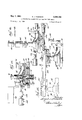
- FIG. 1 is a plan diagrammatic View of apparatus which may be employed in the practice of methods contemplated by the present invention
- FIG. 2 is a fragmentary elevational View taken substantially along the line 2 2 of FIG. l;
- FlG. 3 is an enlarged vertical sectional view taken along the line 3 3 of FIG. 1, Showing the position occupied by the pump housing after it has been delivered to and located upon a supporting xture;
- FlG. 4 is a vertical sectional View taken along the line 4 4 of FlG. l at Station No. 8, more clearly to illustrate the assembled relation of constituent parts of the dg atented May 7, 1963 pump, such as the housing, impeller, seal, shaft and bearing assembly, and pulley hub;
- FIG. 5 is an enlarged sectional view of the seal and retaining washer as shown in FIG. 4, more clearly to illustrate the physical nature of the seal per se;
- FIG. 6 is a detailed horizontal sectional view taken substantially along the line 6 6 of FIG. 4, to show how the opposed peripheral lugs of the retaining washer cooperate with the hub portion of the impeller;
- FIG. 7 is a semi-diagrammatic vertical sectional view at Station No. 1, illustrating the manner in which impellers are fed into position for subsequent assembly with the pump housing at a subsequent station;
- FG. 8 is also a semi-diagrammatic vertical sectional View at Station No. 2, illustrating the manner in which seal devices are delivered into proper position and telescopically associated within the hollow hub portion of the pump impeller which had previously been delivered to Station No. 1;
- FIG. 9 is a semi-diagrammatic view similar to FIGS. 7 and 8 at Station No. 3, illustrating mechanism for shifting retaining washers into proper position and subsequently, telescopically assembled with the hollow hub of the impeller so as to secure in position the seal previously delivered at Station No. 2;
- FlG. 10 is a semi-diagrammatic view in vertical section at Station No. 4, illustrating the manner in which a pump housing is associated with the irnpeller after the aforesaid seal and retaining washer have been applied to the impeller;
- FG. 1l is a semi-diagrammatic vertical sectional view at Station No. 5, yto illustrate the manner in which shaft and bearing assemblies are brought into preliminary assembled relation with the pump housing;
- FIG. 12 is a view similar to FIG. 11 taken at Station No. 6, Kdisclosing the association of the pulley hub with the shaft and bearing assembly previously assembled With the housing at Station No. 5;
- FIG. 13 is, likewise, a semi-diagrammatic vertical sectional View at Station No. 7, illustrating the assembly of a pipe plug with the pump housing;
- FIG. 14 is a view similar to FIG. 13 and is taken at Station No. 8 to illustrate the assembly with the pump housing of a water by-pass nipple at Station No. 8;
- FIG. 15 illustrates the mechanism for transferring a previously assembled pump structure from Station No. 9 to Station No. l0 after the pump housing has been unclamped from its supporting fixture;
- FIG. 16 illustrates the manner in which the completely assembled pump structure is subjected to testing at Station No. 10, from which station defective pumps are delivered to a reject point and satisfactory pumps are delivered to a conveyor;
- FIG. 17 is a plan View of a completely assembled pump as supported and clamped upon its iixture prior to delivery to the testing station;
- FIG. 18 is a plan vieW of the pump shifting mechanism illustrated in FIG. 15, said view being taken substantially along the line 118-18 of FIG. 15;
- FIG. 19 is a detailed sectional view of the clamping mechanism for supporting a completed assembled pump structure prior to its being shifted from Station No. 9 to Station No. 10, said view being taken substantially along the line 19 19 of FIG. 15, with the pump structure shown in elevation; and
- FIG. 20 is a detailed sectional View of the aforesaid clamping mechanism taken along the line 2li-2U of FG. 15.
- the pump is designated kgenerally by the numeral 22.
- This pump 22 includes a pump housing or casting 24 which encloses animpeller 26.
- the impeller 26 is carried by a shaft 28 of a shaft and bearing assembly designatedA generally bythe numeral 30, FIGS. l1 to 13, inclusive.
- a sealing device 34 is also carried within a hollow hub portion 32 of theim'peller 26.
- This sealing device 34 is held in place within the hub extension portion 32 of the impeller by a retainingmember orwasher 36 (see FIGS. 4 to 6, inclusive).
- the Washer 36 is provided with oppositely disposed peripherallugs 38, which are lodged within the complementary recesses provided in the hub portion 32.
- the outer extremity of the shaft 28 carries a pulley hub 40;
- the present invention contemplates improved methods and apparatus whereby the pump parts referred to above may-.be assembled into a completeV pump structure, and thiscomplete pump structure tested under operating conditions with a minimum amount ofeifort and skill on the part of an operatorand with the expenditure of a minimum amountV of time.
- PIG. l it will be seen that one form lof'apparatus for assembly and testing pump structures ⁇ of the type referred to above incorporates an intermittently rotatable table 46.
- This table is preferablyY of annular shape as viewed in plan and is adapted to be shifted intermittently through the agency of a suitable actuating mechanism, such as a hydraulic actuator 48.
- a suitable actuating mechanism such as a hydraulic actuator 48.
- a feed pawl 50 forwardly and rearwardly to impart intermittent movement tothe tablel in the directionindicated by the directional arrow in FIG. 1.
- the pawl 50 is adapted to engage aratchetmember 52 supportedby a vertical shaft 54.
- a suitable spring pressed index pin 56 interlocks with a complementary recess in a disc memberV 58 so as to secure Ythe table 46 in a fixed position during the retracting stroke of thepawl 50; It is this-forward actuating movement of the pawl 50 which causesthe table 46 to be intermittently advanced so as to move a work-holding-xture or plate 60 Ifrom one station to another, these stations being indicated as Ystations numbered from l to 9. It is during the dwell of the table 46 occasioned during the retracting stroke of the pawl 50 that the various assembly and testing operationsV about to be described, take place.
- an impeller 26 is delivered to a complementary fixture plate 60 from a suitable impeller feeder designated, generally, by the numeral 62.
- This feeder may be of any conventional design adapted to supply parts down a chute to a position of association with the xture y6I).
- a hopper 64 of conventional design may be used to keep the feeder mechanism ⁇ 62 supplied with impeller parts. Referring to FIG. 7, it will be noted that the invention contemplates the direction ofA impeller parts from the feeder 62 through a chute 66.
- a hydraulic actuating device or mechanism V68 In the vicinity of the bottom of the chute 66 is a hydraulic actuating device or mechanism V68, which, at the proper interval of time, moves forwardly to shift an impeller located in the vicinity of the bottom of the chute (dotted line position) to the solid line position immediately beneath a secondhydraulic actuator 70.
- This hydraulic actuator 70 is employed to push the impeller 26downwardly into telescopic associa- 'tion with an upwardly projecting pin 72.
- This pin 72 is 4shiftedly supported Vwithin the fixture plate 60 and is resilieutly urged upwardly within a depending portion 74 through the agency of a coil spring, the function of which will be more ⁇ apparent as the description progresses.
- seal-r ri-ng devices 34 are maintained within Va suitable hopper 80.A From the hopper 80, these seal devices are supplied to a.
- a conventional hydraulic actuator 86 is adapted to shift the seal to the solid line position, in coaxial alignment with the previously mentioned pin 72 on ⁇ one side and a
- Advancing movement of the actuator 88 causes the seal 34 to be telescopically associated with the pin 72 so as to occupy the position illustrated in lFIG. 9.
- the seal 34 is held within the hollow hub portion 32 of the impeller 26.
- the impeller and associated seal are now in readiness to be moved from Station No. 2 to Station No. 3 in response to the functioning of the aforementioned hydraulic actuator 48.
- Ia hopper 90 retains a supply of retaining washers 36. These washers are supplied to a conf ventional feeder mechanism 92, and are directed by a chute 94 to the dotted line position illustrated in fFIG. 9. From thisV position the retaining washer may be advanced by a hydraulic actuator 96 from the dotted line position to the solid line position illustrated in FIG. 9; In this latter position, the retaining washer 36 is located in axial yalignment with the pin 72 and a hydraulic actuator 98.y The hydraulic actuator A98 carries an actuating member or head 10i), which is equipped withoppositely disposed lugs 102. As these lugs move downwardly, they are brought into engagement with complementary oppositely disposed lug portions G8 (see FIG.
- an operator removes a pump housing 22 from a conveyor 104 and places the housing in Vsuperimposed relation with respect to the impeller 26 and parts previously vassembled therewith.
- the housing 22 is manually located byY dowels 1106.
- the housing is in readiness to be yclamped against the supporting xture 60 by a suitable clamping device designated, generally, by the numeral 108.
- 108 is disclosed I more in detail.
- a con ventional hydraulic actuator mechanism .110 may be employed. As the pistonv of this actuator advances, it is Station No. 5
- shaft and bearing assemblies 30 are drctztdailrom a feeder 112 through a chute 114-t o the dotted position ⁇ shown in FIG. l1.
- a hydraulic actuator 116 is adapted to shift the assembly into axial alignment with a bearing sect1on of the pump housing 24 and a hydraulic actuator 118.
- the actuator l118 serves to move the ⁇ assembly 38 downwardly into telescopic ⁇ association with the bearing section of the housing 24.
- pulley hub members 48 are directed from a suitable feeder 1122 through a chute 124.
- Conventional storage means, 1 serves to retain a supply of hub members 4t) ⁇ for delivery to the ⁇ feeder 122.
- a hydraulic ⁇ actuator 128 vserves lto shift hub members 40 from ⁇ the dotted to the solid lme position shown in FIG. l2.
- a hydraulic actuator 130 then functions to telescopically associate the hub member 40 with the exposed portion of the shaft 218 of .the assembly 30. With the hub ⁇ member 40 thus forced into position upon the shaft 28, the pump structure may now be shifted to Station No. 7, through the agency of the actuator 48 which operates the pawl 50 previously described.
- water plugs are directed from a suitable feeder 132 through a chute 134 into axial alignment with a torque wrench mechanism designated, generally, by the numeral 136.
- This mechanism 136 may be of the conventionally rotatable overload release type; and as it is moved forwardly during the rotation thereof by a suitable hydraulic actuator :138, the head of the plug 42 is engaged so ⁇ as to cause the plug to be screwed into a complementary aperture in the pump housing.
- the torque mechanism 136 Upon retract-ion of the torque mechanism 136 following the proper positioning of the plug y42, the assembled pump unit may -be shifted to Station No. 8.
- water by-pass nipples 44 are directed from a suitable feeder mechanism 140 through a chute 142 to the position in FIG. 14.
- a hydraulic actuator l144 then functions to move a conventional rotatable torque wrench mechanism 146 to the right, FIG. 14, into engagement with the head of the water bypass nipple 44. This causes the nipple 44 to be screwed into a complementary threaded aperture in the pump housing.
- actuator 144 serves to retract the torque wrench mechanism 146, and the pump unit is now ready to be shifted to Station No. 9. All of the constituent elements of the pump have now been assembled and the device is ready for testing.
- the previously assembled pump structure must be unclamped from the supporting fixture or plate 66.
- These hydraulic actuators 148 function simultaneously so as to engage the clamp structures 108, as illustrated in FIG. 15. This causes the clamps 108 to become disengaged from the pump housing 24, thus permitting the coil spring 118 to urge the pin 72 upwardly.
- the upward movement of the pin 72 causes the pump housing 24 to become disengaged from the locating pins 1116, and the pulley hub 40 is forced between a pair of clamp jaws 151i (see, particularly, FIGS. 18 to 20, inclusive).
- the extent of upward movement of the supporting fixture or means 60 is limited by the head of a pin 149 (FIG. 3).
- the fork 156 has reached a position beneath the pulley hub 40 and, thus, the entire pump structure is elevated suiciently to clear the upper projecting portion of the pin 72.
- the pulley hub 4@ causes the pulley hub 4@ to be disengaged from the clamping jaws 159 and ultimately shifted to the dotted position shown in FIG. 15.
- the housing has become located at Station No. 10 in readiness for testing.
- a hydraulic actuator 172 function to move a sealing member 174 into sealing engagement with the outer extremity of the water by-pass nipple 44.
- a second hydraulic actuator 176 causes a sealing and water conducting head -178 to be sealed against the outlet passages 180 of the pump structure.
- a third hydraulic actuator 182 causes a rotary torque mechanism 184 to be moved downwardly into driving engagement with the pulley hub 40.
- Applicant is a hydraulic engineer of long (standing, andas will appear from many patents which have been-issued to him, hydraulic units, actuators and thelike, as well as controls therefor, have heretofore been used extensively in instances Where sequential, timed funct-ioning of machine elements and the like is required.
- Apparatus for-sequentially assemblingpumps on a Ymass productionl basis comprising, in combination, an f interconnected series of. assembly hutures, indexing means rfor intermittently indexing said xtures in unison to locatethe individual tix-tures in successive assembly stations,
- a eachof said fixtures including upwardly protruding ⁇ housing locating means and includingia ⁇ depressible alignment element which'protrudes upwardly, Virnpeller supy.plyirig meansufor'supplying pump impellers to one of said stations, Vimpeller applying means located at said one ⁇ -stat'io'n'for applyingrpump' impellers into intertltting relation to the alignment Ielements of successive assembly iixtures moved into said one station, a later one of said stations ⁇ constituting a housing applying station, pump shaft supplying means mounted to -supply pump shafts to a'third one of said'stations, Vpump shaft applyingmeans
- pump receiving means disposed 'in coacting relation tofa still later one of said stations to receive assembled pumps moved into lsaid last mentioned'station, trackmeanssupporting said pump receiving means andextending away yfrom said last mentioned station, hydraulic vactuating means operating at said las-t mentioned' station tofmove said pumprecei-ving means along said ⁇ Stra-ck means-to transfer successive Iassembled pumps ⁇ away from'said last mentioned station, and'said track means bei-ng shaped to effect lifting of said receiving meansand the assembled pump supported thereby upwardly from the housing'loeating means ofthe associated assembly'xture'automatically as an incident to movement ofsaid receiving means along the track means by said actuating means.
- Apparatus vfor sequentially assembling Vandv'te'sting pumps comprising, in combination, a rotatable assembly table, an'fannular. series of support ⁇ iixtuies on said table, indexing' means coacting with said table'tointer'mittently index the latter rotatably to move said fixture-s vto successive ones cfan annular 4series of stationsyeach ofsaid positioned 'in the associated station, hydraulically'actuated pusher means'mounted at'each of said plurality 'of stations to move a' par-t Ifrom' the associated transfer means :axially Vinto an 'assembled position von the iixture in the associated station, pump housing clamping means onfeach of -said tixtures, an intermediate one of said stations constitutinga housing assembly station andL beingY equipped with hydraulic actuating means for' applying the-housing clamping means of the fixtures in the housing assembly station, another :one of Vsaid stations constituting a transter station equipped with
- Apparatus'for sequentially assembling water pumps comprising, in combinationpa'rotary table, ⁇ an annular series of .iixture platesloc'ated 'onV saidtable'v in circumferentially spaced relation to each other, coiled'compres- -sionY springs yieldably supporting each of said-.plateson said table, a depressible locating plunger mounted iueach fixture plate andrfbeing spring urged upwardly to a guiding position projecting Aabove the coactingplate, indexing meansvcoacting with said table to index the latter rotatably to movefsaid platesto successiveon'es'of 'an annular series of stations, pump impeller supply means at a first one of said stations, hydraulically operated impeller transfer means at said first station for moving pump impellers from said supply means into overlying coaxial relation to a locating plunger indexed into said first station, hydraulically lactuated pusher means in said first station positioned to move impellers downwardly from the impeller
- Apparatus for sequentially assembling 'and testing pumps comprising, in combination, a rota-table assembly table, an annular series of support fixtures on said table, indexing means coacting with said table to intermittently index the latter rotatably to move said fixtures to successive ones of an annular series of stations, each of said fixtures including a depressible locating plunger spring urged upwardly to a normal position; a plurality of said stations being equipped respectively with impeller supply means, sealing element supply means, washer supply means, pu-mp shaft and bearing supply means, and pulley hub supply means; hydraulically actuated transfer means associated with each of said plurality of stations to transfer parts from the associated supply means into overlyin-g concentric relation to the locating plunger of the fixtures positioned in the associated station, hydraulically actuated pusher means mounted at each of said plurality of stations to move a part from the associated transfer means axially into an assembled position on the fixture in the associated station, pump housing 4clamping means on each of said fixtures, an intermediate one of said stations in said series
- Apparatus for assembling water pumps comprising, in combination, a rotary table, an annular series of assembly fixtures mounted on said table, a depressible locating plunger mounted in each fixture and -being spring urged upwardly to a projecting guiding position, indexing means coacting with said table to index the latter rotatably to move said fixtures through a series of stations, hydraulically operated impeller transfer means at said first one of said stations for moving pump impellers into overlying coaxial relation to a locating plunger indexed into said first station, hydraulically actuated pusher means in said rst station positioned to move impellers downwardly from the impeller transfer means into telescoped relation to the locating plunger in said first station, hydraulically actuated seal transfer means positioned in a second one of said stations to transfer seals into overlying coaxial relation to a locating plunger in said second station, hydraulically actuated pusher means positioned in said second station to move seals downwardly from the seal transfer means into telescoped relation to a locating
- Apparatus for assembling centrifugal pumps comprising, in combination, a rotary table, an annular series of assembly xtures -on saidtahle, a depressigble locating plunger mounted inveach fixture, indexing means coacting with Vsaid table to index the latter to move saidv xtures through a series of stations, pump impeller ⁇ feeding means at a iirstone of said stations,y hydraulically actuated -pusher means positioned atsaid Vrst station to move impellers axially into telescoped relation to the plunger in alixture in said rst station, Iseal feeding means positioned to feed impeller seals to asecondone of said stations, hydraulically actuated pusher means positioned insaidsecond station to move seals axially into telescoped relation to a locating plunger in said secondistation, Washer supply means positioned in a third one of said stations, a hydraulically actuated pusher mounted in saidthird station to move washers into
- hydraulic pusher means positioned in said sixth station for moving pulley hubs axially into assembled Yrelation to pump shafts, another one of said stations constituting a transfer station equippedwith hydraulic clamp release means lfor releasing Vthe housing clamps on xtures moved into the transfer station, hydraulically actuated transfer means for moving pump assemblies from said transfer station to a test station removed ⁇ from the-path of said fixtures, andrrpump testing means mounted in said test station for testing pump assemblies moved thereinto.
Description
APPARATUS PoR ASSEMBLING AND TESTING PUMP PARTS Filed Sept. 11, 1958 E. J. SVENSON May 7, 1963 6 Sheets-Sheet 1 May 7, 1963 E. J. svENsoN 3,088,198
APPARATUS PoR ASSET/[BLING AND TESTING PUMP PARTS Filed sept. 11, 1958 A s sheets-sheet 2 l 15.* LQ/HINT 'Il lo Q 105 im Il;
mnn nuv May 7, 1963 .5. J. svENsoN 3,088,198
APPARATUS FOR ASSEMBLING AND TESTING PUMP PARTS Filed Sept. ll, 1958 6 Sheets-Sheet 3 INV ENTOR. jfvzas Meadow May 7, 1953 E. J. svENsoN 3,088,198
APPARATUS FOR ASSEMBLING AND TESTING PUMP PARTS Filed Sept. ll, 1958 6 Sheets-Sheet 4 E. J. svENsoN 3,088,198
APPARATUS FoP ASSEMBLING AND TESTING PUMP PARTS May 7, 1963 6 Sheets-Sheet 5 Filed Sept. ll, 1958 T TTT.
....ll l,
May 7, 1963 E. J. svENsoN 3,088,198
APPARATUS FOR ASSEMBLING AND TESTING PUMP PARTS Filed Sept. l1, 1958 6 Sheets-Sheet 6 A a? 'vlag l N VENTOR.
rg/J.
llnited States @arent "a" 3,088,198 APPARATUS FR ASSEMBLING AND TESINE PUMP PARTS Ernest J. Svenson, Rockford, lll., assigner to (Edin Corporation, Rockford, Ill., a corporation of Illinois Filed Sept. 11, 1958, Ser. No. 769,355 7 Claims. (QL 29 2i8) This invention relates to improvements in methods and apparatus for assembling and testing parts, and more particularly to an apparatus for assembling the constituent parts of water pumps, as, for example, water pumps of the type used in automobiles, trucks, and vehicles of like nature.
Production line methods have, for a number of years, been used to reduce the cost to the ultimate consumer of such ydevices as automobiles, refrigerators, radio, and television equipment, and the like. The present invention contemplates further reduction in cost to the ultimate consumer of devices in which a water pump forms a part of the general combination. It has heretofore been common procedure in assembling devices such as water pumps, to practice methods of assembly which are not consistent with the principle of low cost to the consumer. It is, therefore, one of the primary objects of the present invention to provide an apparatus which will insure a high degree of eliiciency in the assembly and testing of water pumps, and the like.
Water pumps of the type contemplated by the present invention consist of a number of parts, such as a pump housing, impeller, seals, retaining washer, shaft and bearing assembly, pulley hub, pipe plug, and water by-pass nipple. Heretofore, manual assembly of the parts just enumerated has not proven to be elicient, and the present invention contemplates an apparatus whereby such parts may be assembled with a minimum amount of manual elfort and Within limited oor space. To this end, the invention contemplates the intermittent advancement of various parts, beginning with the pump housing, along a predetermined path from one station to another, Whereby to accomplish expeditiously and economically the assembly and ultimate testing of the pump structure.
It is a further object of the present invention to accomplish the assembly and testing of pump structures by directing constituent parts into the above mentioned predetermined path, shifting such parts into their proper assembled relation during periods of intermittent dwell and finally subjecting the assembled parts to operational testing after removing the pump structure from said predetermined path.
lt is a further object of the present invention to employ as far as possible, standardized equipment at the various stations of assembly md, thus, reduce to a minimum added costs which would otherwise result when specially designed equipment is employed.
The foregoing and other objects and advantages will be more apparent from the following detailed description when considered in connection with the occompanying drawings wherein:
FIG. 1 is a plan diagrammatic View of apparatus which may be employed in the practice of methods contemplated by the present invention;
FIG. 2 is a fragmentary elevational View taken substantially along the line 2 2 of FIG. l;
FlG. 3 is an enlarged vertical sectional view taken along the line 3 3 of FIG. 1, Showing the position occupied by the pump housing after it has been delivered to and located upon a supporting xture;
FlG. 4 is a vertical sectional View taken along the line 4 4 of FlG. l at Station No. 8, more clearly to illustrate the assembled relation of constituent parts of the dg atented May 7, 1963 pump, such as the housing, impeller, seal, shaft and bearing assembly, and pulley hub;
FIG. 5 is an enlarged sectional view of the seal and retaining washer as shown in FIG. 4, more clearly to illustrate the physical nature of the seal per se;
FIG. 6 is a detailed horizontal sectional view taken substantially along the line 6 6 of FIG. 4, to show how the opposed peripheral lugs of the retaining washer cooperate with the hub portion of the impeller;
FIG. 7 is a semi-diagrammatic vertical sectional view at Station No. 1, illustrating the manner in which impellers are fed into position for subsequent assembly with the pump housing at a subsequent station;
FG. 8 is also a semi-diagrammatic vertical sectional View at Station No. 2, illustrating the manner in which seal devices are delivered into proper position and telescopically associated within the hollow hub portion of the pump impeller which had previously been delivered to Station No. 1;
FIG. 9 is a semi-diagrammatic view similar to FIGS. 7 and 8 at Station No. 3, illustrating mechanism for shifting retaining washers into proper position and subsequently, telescopically assembled with the hollow hub of the impeller so as to secure in position the seal previously delivered at Station No. 2;
FlG. 10 is a semi-diagrammatic view in vertical section at Station No. 4, illustrating the manner in which a pump housing is associated with the irnpeller after the aforesaid seal and retaining washer have been applied to the impeller;
FG. 1l is a semi-diagrammatic vertical sectional view at Station No. 5, yto illustrate the manner in which shaft and bearing assemblies are brought into preliminary assembled relation with the pump housing;
FIG. 12 is a view similar to FIG. 11 taken at Station No. 6, Kdisclosing the association of the pulley hub with the shaft and bearing assembly previously assembled With the housing at Station No. 5;
FIG. 13 is, likewise, a semi-diagrammatic vertical sectional View at Station No. 7, illustrating the assembly of a pipe plug with the pump housing;
FIG. 14 is a view similar to FIG. 13 and is taken at Station No. 8 to illustrate the assembly with the pump housing of a water by-pass nipple at Station No. 8;
FIG. 15 illustrates the mechanism for transferring a previously assembled pump structure from Station No. 9 to Station No. l0 after the pump housing has been unclamped from its supporting fixture;
FIG. 16 illustrates the manner in which the completely assembled pump structure is subjected to testing at Station No. 10, from which station defective pumps are delivered to a reject point and satisfactory pumps are delivered to a conveyor;
FIG. 17 is a plan View of a completely assembled pump as supported and clamped upon its iixture prior to delivery to the testing station;
FIG. 18 is a plan vieW of the pump shifting mechanism illustrated in FIG. 15, said view being taken substantially along the line 118-18 of FIG. 15;
FIG. 19 is a detailed sectional view of the clamping mechanism for supporting a completed assembled pump structure prior to its being shifted from Station No. 9 to Station No. 10, said view being taken substantially along the line 19 19 of FIG. 15, with the pump structure shown in elevation; and
FIG. 20 is a detailed sectional View of the aforesaid clamping mechanism taken along the line 2li-2U of FG. 15.
Referring now to the drawings more in detail, wherein like nurnerals have been employed to designate similar parts throughout the various views, it is deemed advisable to facilitate understanding of the present invention 4to describe one form of water pump of the type capable of being assembled by practicing the method contemplated hereby.V It will be seen from a number of the figures that the pump is designated kgenerally by the numeral 22. This pump 22 includes a pump housing or casting 24 which encloses animpeller 26. The impeller 26 is carried by a shaft 28 of a shaft and bearing assembly designatedA generally bythe numeral 30, FIGS. l1 to 13, inclusive. Also carried within a hollow hub portion 32 of theim'peller 26 is a sealing device 34, best shown in IG, 5. This sealing device 34 is held in place Within the hub extension portion 32 of the impeller by a retainingmember orwasher 36 (see FIGS. 4 to 6, inclusive). The Washer 36 is provided with oppositely disposed peripherallugs 38, which are lodged within the complementary recesses provided in the hub portion 32. The outer extremity of the shaft 28 carries a pulley hub 40;
and as shown inVFIGS. 13 to 17, inclusive, there is associa'ted with the pump housing 24 a pipe plug 42 and a bypass nipple 44.
The present invention contemplates improved methods and apparatus whereby the pump parts referred to above may-.be assembled into a completeV pump structure, and thiscomplete pump structure tested under operating conditions with a minimum amount ofeifort and skill on the part of an operatorand with the expenditure of a minimum amountV of time. Referring to PIG. l, it will be seen that one form lof'apparatus for assembly and testing pump structures `of the type referred to above incorporates an intermittently rotatable table 46. This table is preferablyY of annular shape as viewed in plan and is adapted to be shifted intermittently through the agency of a suitable actuating mechanism, such as a hydraulic actuator 48.- 'Ihisactuator 48 is designed to shift a feed pawl 50 forwardly and rearwardly to impart intermittent movement tothe tablel in the directionindicated by the directional arrow in FIG. 1. The pawl 50 is adapted to engage aratchetmember 52 supportedby a vertical shaft 54. As the pawl 50 reaches the limitof its forward movement, a suitable spring pressed index pin 56 interlocks with a complementary recess in a disc memberV 58 so as to secure Ythe table 46 in a fixed position during the retracting stroke of thepawl 50; It is this-forward actuating movement of the pawl 50 which causesthe table 46 to be intermittently advanced so as to move a work-holding-xture or plate 60 Ifrom one station to another, these stations being indicated as Ystations numbered from l to 9. It is during the dwell of the table 46 occasioned during the retracting stroke of the pawl 50 that the various assembly and testing operationsV about to be described, take place.
Station No. 1
Y At StationNo. l, an impeller 26 is delivered to a complementary fixture plate 60 from a suitable impeller feeder designated, generally, by the numeral 62. This feeder may be of any conventional design adapted to supply parts down a chute to a position of association with the xture y6I). A hopper 64 of conventional design may be used to keep the feeder mechanism `62 supplied with impeller parts. Referring to FIG. 7, it will be noted that the invention contemplates the direction ofA impeller parts from the feeder 62 through a chute 66. In the vicinity of the bottom of the chute 66 is a hydraulic actuating device or mechanism V68, which, at the proper interval of time, moves forwardly to shift an impeller located in the vicinity of the bottom of the chute (dotted line position) to the solid line position immediately beneath a secondhydraulic actuator 70. This hydraulic actuator 70 is employed to push the impeller 26downwardly into telescopic associa- 'tion with an upwardly projecting pin 72. This pin 72 is 4shiftedly supported Vwithin the fixture plate 60 and is resilieutly urged upwardly within a depending portion 74 through the agency of a coil spring, the function of which will be more `apparent as the description progresses. Suit- Station No. 2
At Station No. 2 (see FIGS. l and 8), a supply of seal-r ri-ng devices 34 is maintained Within Va suitable hopper 80.A From the hopper 80, these seal devices are supplied to a.
Station No. 3
At Station No. 3, Ia hopper 90 retains a supply of retaining washers 36. These washers are supplied to a conf ventional feeder mechanism 92, and are directed by a chute 94 to the dotted line position illustrated in fFIG. 9. From thisV position the retaining washer may be advanced by a hydraulic actuator 96 from the dotted line position to the solid line position illustrated in FIG. 9; In this latter position, the retaining washer 36 is located in axial yalignment with the pin 72 and a hydraulic actuator 98.y The hydraulic actuator A98 carries an actuating member or head 10i), which is equipped withoppositely disposed lugs 102. As these lugs move downwardly, they are brought into engagement with complementary oppositely disposed lug portions G8 (see FIG. 6) of the retaining washer so as to move said lug portions into regisf tration lwith complementary recesses in the wall `of the impeller hubV3-2. During this step in the operation, the retainingwasher is pressed against the upper or outer side o-f the seal device 64, as` clearly shown in FIG. 10. With the retaining washer 36 thus assembled with the impeller hub 32, the supporting fixture 60 is advanced fromY Station No. 3 to StationrNo. 4.
Station No. 4
As illustrated in FIG. 1, an operator removes a pump housing 22 from a conveyor 104 and places the housing in Vsuperimposed relation with respect to the impeller 26 and parts previously vassembled therewith. Thus, las shown in FIG. 10, the housing 22 is manually located byY dowels 1106. lIn thisposition, the housing is in readiness to be yclamped against the supporting xture 60 by a suitable clamping device designated, generally, by the numeral 108. In FIG. 3, the clamping device |108 is disclosed I more in detail. To shift the pivotally mounted clamping device 103 from unclamped to clamped position, a con ventional hydraulic actuator mechanism .110 may be employed. As the pistonv of this actuator advances, it is Station No. 5
'on No. 5, shaft and bearing assemblies 30 are drctztdailrom a feeder 112 through a chute 114-t o the dotted position `shown in FIG. l1. From this position, a hydraulic actuator 116 is adapted to shift the assembly into axial alignment with a bearing sect1on of the pump housing 24 and a hydraulic actuator 118. The actuator l118 serves to move the `assembly 38 downwardly into telescopic `association with the bearing section of the housing 24. As the shaft y28 of the :assembly .116 moves downwardly into the pump housing, it 1s brought into engagement with the upper extremity of the pm 72 and forces the pin 72 downwardly so as to eject 1t from telescop1c association with the retaining washer 36 and the seal 34. The pin 72, when thus shifted by .the shaft 2S of the assembly 30, compresses a coil spring 118 interposed between a collar 121i= secured to the pin 72. and a threaded plug 121. In other words, the pin 72 1s moved downwardly against the yieldable res1stance of the spring 118.. In this manner, the shaft and bearmg asesmbly 3G 1s ultimately shifted to its position of lfinal assembly w1t-h the pump housing, as shown in FIG. l2. The Iforced fit of the bearing portion of the assembly 3i) within the complementary wall portion of the pump housing is suicient to prevent the force of the spring 11S from dislodgmg the assembly lfrom the housing. With the assembly 30 thus associated with fthe pump housing, the pump structure is in readiness to be shifted to Station No. 6.
Station N0. 6
At Station No. 6 (see FIGS. 1 and 12), pulley hub members 48 are directed from a suitable feeder 1122 through a chute 124. Conventional storage means, 1, serves to retain a supply of hub members 4t) `for delivery to the `feeder 122. A hydraulic `actuator 128 vserves lto shift hub members 40 from `the dotted to the solid lme position shown in FIG. l2. A hydraulic actuator 130 then functions to telescopically associate the hub member 40 with the exposed portion of the shaft 218 of .the assembly 30. With the hub `member 40 thus forced into position upon the shaft 28, the pump structure may now be shifted to Station No. 7, through the agency of the actuator 48 which operates the pawl 50 previously described.
Station No. 7
At Station No. 7, FIG. 13, water plugs are directed from a suitable feeder 132 through a chute 134 into axial alignment with a torque wrench mechanism designated, generally, by the numeral 136. This mechanism 136 may be of the conventionally rotatable overload release type; and as it is moved forwardly during the rotation thereof by a suitable hydraulic actuator :138, the head of the plug 42 is engaged so `as to cause the plug to be screwed into a complementary aperture in the pump housing. Upon retract-ion of the torque mechanism 136 following the proper positioning of the plug y42, the assembled pump unit may -be shifted to Station No. 8.
Station N0. 8
At Station No. 8 (see FIGS. 1 and 14), water by-pass nipples 44 are directed from a suitable feeder mechanism 140 through a chute 142 to the position in FIG. 14. A hydraulic actuator l144 then functions to move a conventional rotatable torque wrench mechanism 146 to the right, FIG. 14, into engagement with the head of the water bypass nipple 44. This causes the nipple 44 to be screwed into a complementary threaded aperture in the pump housing. After the nipple 44 has been secured in position, actuator 144 serves to retract the torque wrench mechanism 146, and the pump unit is now ready to be shifted to Station No. 9. All of the constituent elements of the pump have now been assembled and the device is ready for testing.
6 Station N0. 9
At Station No. 9, FIG. 15, the previously assembled pump structure must be unclamped from the supporting fixture or plate 66. This is accomplished by hydraulic actuators 148 (see FIGS. 1 and 15). These hydraulic actuators 148 function simultaneously so as to engage the clamp structures 108, as illustrated in FIG. 15. This causes the clamps 108 to become disengaged from the pump housing 24, thus permitting the coil spring 118 to urge the pin 72 upwardly. The upward movement of the pin 72 causes the pump housing 24 to become disengaged from the locating pins 1116, and the pulley hub 40 is forced between a pair of clamp jaws 151i (see, particularly, FIGS. 18 to 20, inclusive). The extent of upward movement of the supporting fixture or means 60 is limited by the head of a pin 149 (FIG. 3). 'I'hese clamping jaws 151D are resiliently urged toward each other by coil springs 152 housed within a frame structure 154. The entire pump unit has now been elevated to a position which will permit a fork member 156 to pass beneath the flange poriton of the pulley hub 40. The advancement of the fork 156 is accomplished by a suitable hydraulic actuator 158. This actuator 158 is pivotally supported at 160, FIG. 15, and the opposite portion of the actuator, namely, the piston rod, carries a pair of rollers 162. As these rollers 162 advance along the upper surfaces of elongated cam or rail members 164, they are eventually brought into contact with the rise 166 of said cam members. At this point, the fork 156 has reached a position beneath the pulley hub 40 and, thus, the entire pump structure is elevated suiciently to clear the upper projecting portion of the pin 72. Continued advancement of the `fork 156 causes the pulley hub 4@ to be disengaged from the clamping jaws 159 and ultimately shifted to the dotted position shown in FIG. 15. At this position, the housing has become located at Station No. 10 in readiness for testing.
Station No. 10
As the fork 156 is disengaged from the pulley hub 40 upon the return stroke of the actuator 158, the pump structure is brought to rest upon a plate 16S, FIG. 16. This plate 168 functions in the nature of a sealing plate and carries a water inlet conduit 170. As the pump structure is located in this position, a hydraulic actuator 172 function to move a sealing member 174 into sealing engagement with the outer extremity of the water by-pass nipple 44. Simultaneously, a second hydraulic actuator 176 causes a sealing and water conducting head -178 to be sealed against the outlet passages 180 of the pump structure. A third hydraulic actuator 182 causes a rotary torque mechanism 184 to be moved downwardly into driving engagement with the pulley hub 40. This causes the pump to be rotated at its required speeds, and water directed through the inlet conduit and outlet conduit 186 is subjected to normal operating conditions. If the pump meets the required high and low pressure tests, the completely assembled structure is now in readiness to be shifted by a suitable unloading position designated, generally, by the numeral 188, FIG. 1, to a finished unit conveyor 199. If the pump, as tested, does not meet the prescribed requirements for test, it is shifted to a reject conveyor 192. By having thel pressure testing conducted at a point spaced outwardly from the path of movement taken by the pump parts during the assembly thereof, splash and drain conditions incident to the testing operation does not interfere or in any way contaminate the parts being assembled at the various stations along the predetermined path of assembly. Various conventional pressure responsive and indicating devices (not shown) may be employed in performance of the tests.
Obviously, conventional hydraulic units, such as the units 194 and 196 as well as the control console 198 diagrammatically illustrated in FIG. l, may be used to control the automatic functioning of the mechanisms previously described. It is not necessary for a clear understanding of the present invention to include all of the details of such arrangements-'and it will suihce to say that A the various-.hydraulic actuators and the'like previously described maybe automatically controlled from a central .fpoint in a manner-wellknown to those skilled in this particular art. y. Applicant is a hydraulic engineer of long (standing, andas will appear from many patents which have been-issued to him, hydraulic units, actuators and thelike, as well as controls therefor, have heretofore been used extensively in instances Where sequential, timed funct-ioning of machine elements and the like is required.
Y From the foregoing, it will beapparent that the present invent-ion makes itpossible to perform, in sequence, assembling operations, and finally 'a testing operation which makes for -increased eiliciency, aswell as accuracyin'production. By-intermittentlyrmoving pump parts along a ,"predetermined.pathithrough a series of'assembly stations,
Y and'finally to a-testing station, manual labor is reduced to a` minimum, and the entire operation may be carried on Within a very limited floor space or area. The latter is o f extreme importance in these days of high costs of building construction. `Furthermore, the assembly operations or steps previously described may be carried out by -unskilled persons, as distinguished from previously known methods and apparatus requiring the use of skilled Workmen.
While -certain specific disclosures have been made heret infthe invention isnot, of necessity, limited to such disdor vintermittently indexing vthe latter to a succession of angularly spaced positions to locate the individual assembly -iixtures in a succession ofy assembly stations, pump impeller supplying means located ata -rstpf'said assembly-stations, pump impeller applying means at said fiirstf'sta-tion for applying a pump impeller to theassembly dixture in said'rst station, eachassembly -iixture'includ- Ving va yieldably supported depressible impeller locating f element, sealing device supply means located `at a second Vofvsad stations, sealing device applying means at said Ysecond-station ttor applying-a `sealing device to a pump I ini-pelletsupportedY by the lassembly lixture in said second f station, each Iof said Iassembly'iixtures including housing v clamping means, clamp applying means located at athird one ofvsaid stationsfor Veecting clamping of a pump Vhousingapplied to avpump impeller supported by the assemb-lyfxture in the thirdV station, pump shaft supply means located Vat a -fourthone of said stations, pump shaft applying means at said -fourthstation for applying a pump shaft to'a housing encased pump impeller supported by -the assembly jiixture in said'fourth station, transferY means ylocated at a ifth Vone of'said stations for transferring -rto a testing station successive assembled pumps moved fro-the fifth stationbysaid 'assembly fixtures, pump driving means at said testing station movable into driving relation Y fto.an assembled pump-insaid testing station, anduid supply and discharge means at said testin g station movable into connected relation to a pump in said testing station. Y2. Apparatus for-sequentially assemblingpumps on a Ymass productionl basis, comprising, in combination, an f interconnected series of. assembly hutures, indexing means rfor intermittently indexing said xtures in unison to locatethe individual tix-tures in successive assembly stations, A eachof said fixtures including upwardly protruding `housing locating means and includingia `depressible alignment element which'protrudes upwardly, Virnpeller supy.plyirig meansufor'supplying pump impellers to one of said stations, Vimpeller applying means located at said one `-stat'io'n'for applyingrpump' impellers into intertltting relation to the alignment Ielements of successive assembly iixtures moved into said one station, a later one of said stations `constituting a housing applying station, pump shaft supplying means mounted to -supply pump shafts to a'third one of said'stations, Vpump shaft applyingmeans located` at said third station for applying' pump shafts to successive housing encased pump impellerssupported-by successivev assembly'xtures moved into saidthird-station,
pump receiving means disposed 'in coacting relation tofa still later one of said stations to receive assembled pumps moved into lsaid last mentioned'station, trackmeanssupporting said pump receiving means andextending away yfrom said last mentioned station, hydraulic vactuating means operating at said las-t mentioned' station tofmove said pumprecei-ving means along said `Stra-ck means-to transfer successive Iassembled pumps `away from'said last mentioned station, and'said track means bei-ng shaped to effect lifting of said receiving meansand the assembled pump supported thereby upwardly from the housing'loeating means ofthe associated assembly'xture'automatically as an incident to movement ofsaid receiving means along the track means by said actuating means.
3. Apparatus vfor sequentially assembling Vandv'te'sting pumps comprising, in combination, a rotatable assembly table, an'fannular. series of support `iixtuies on said table, indexing' means coacting with said table'tointer'mittently index the latter rotatably to move said fixture-s vto successive ones cfan annular 4series of stationsyeach ofsaid positioned 'in the associated station, hydraulically'actuated pusher means'mounted at'each of said plurality 'of stations to move a' par-t Ifrom' the associated transfer means :axially Vinto an 'assembled position von the iixture in the associated station, pump housing clamping means onfeach of -said tixtures, an intermediate one of said stations constitutinga housing assembly station andL beingY equipped with hydraulic actuating means for' applying the-housing clamping means of the fixtures in the housing assembly station, another :one of Vsaid stations constituting a transter station equipped with hydraulically vactuatedhousing clamp releasing means, two yieldably supported pulley hub guide jaws located at said transfer station in elevated positions to receive therebetweenthe pulley hubsorf pump assemblies moved into the transfer station and released by the coacting housing vclamping means, a transfer track u the pump assembly to said testingstation, and hydrauli- `cally actuatedsealingand testing means located in said -testing station for coaction' with pump assemblies trans- `ferred to said testing station. l t
'4. Apparatus'for sequentially assembling water pumps, comprising, in combinationpa'rotary table, `an annular series of .iixture platesloc'ated 'onV saidtable'v in circumferentially spaced relation to each other, coiled'compres- -sionY springs yieldably supporting each of said-.plateson said table, a depressible locating plunger mounted iueach fixture plate andrfbeing spring urged upwardly to a guiding position projecting Aabove the coactingplate, indexing meansvcoacting with said table to index the latter rotatably to movefsaid platesto successiveon'es'of 'an annular series of stations, pump impeller supply means at a first one of said stations, hydraulically operated impeller transfer means at said first station for moving pump impellers from said supply means into overlying coaxial relation to a locating plunger indexed into said first station, hydraulically lactuated pusher means in said first station positioned to move impellers downwardly from the impeller transfer means into telescoped relation to the plunger in said first station, seal supply means positioned to supply seals to a second one of said stations, hydraulically actuated .transfer means positioned at said second station positioned to transfer seals horizontally into overlying coaxial relation to a locating plunger in said second station, hydraulically actuated pusher means positioned in said second station to move seals downwardly from the seal transfer means into telescoped relation to a locating plunger in said second station, washer supply means positioned in a third one of said stations, hydraulically actuated transfer means positioned at said third station for moving washers horizontally from said washer supply means into overlying coaxial relation to a plunger in said third station, ya hydraulically actuated pusher mounted in said third station to move washers into telescoping relation to locating plungers therein, each of said fixture plates including housing locating projections thereon, pump housing clamp means associ-ated with each of said fixture plates, a fourth one of the stations constituting la housing loading station equipped with hydraulic `actuating means for operating the housing clamps of fixture plates moved into the fourth station, shaft and hearing feeding means positioned in a fifth one of said stations, hydraulically ractuated transfer means mounted in said fifth station for moving shafts and bearings horizontally into overlying -coaxial relation to locating plungers indexed into said fifth station; hydraulically actuated pusher means positioned in said fth station for moving shafts and bearings downwardly into telescoped relation to housings, washers, seals, and impellers located in the fifth station thereby depressing locating plungers in said fifth station, pulley -hub feeder means in a sixth one of said stations, hydraulic transfer means for moving said pulley hubs horizontally into coaxial relation to pump shafts in said sixth station, hydraulic pusher means positioned in said sixth station for moving pulley hubs axially into assembled relation to ptunp shafts, another one of said stations constituting a transfer station in which two pulley hub guide jaws are yieldably mounted in elevated positions, hydraulic `clamp release means positioned in said transfer station to release housing clamps therein to effect upward movement into guided relation to said jaws of a pump assembly in said transfer station yby the spring urged locating plunger in said transfer station, a transfer fork supported on :a track extending across the transfer station to a test station, hydraulic actuating means for moving said transfer fork `along said track to move pump assemblies from said transfer station to said test station, said track defining a rise therein alined with said transfer station to effect lifting of a pump assembly from said `transfer station for movement to said test station, and pump testing means mounted in said test station for testing pump assemblies moved thereinto.
5. Apparatus for sequentially assembling 'and testing pumps comprising, in combination, a rota-table assembly table, an annular series of support fixtures on said table, indexing means coacting with said table to intermittently index the latter rotatably to move said fixtures to successive ones of an annular series of stations, each of said fixtures including a depressible locating plunger spring urged upwardly to a normal position; a plurality of said stations being equipped respectively with impeller supply means, sealing element supply means, washer supply means, pu-mp shaft and bearing supply means, and pulley hub supply means; hydraulically actuated transfer means associated with each of said plurality of stations to transfer parts from the associated supply means into overlyin-g concentric relation to the locating plunger of the fixtures positioned in the associated station, hydraulically actuated pusher means mounted at each of said plurality of stations to move a part from the associated transfer means axially into an assembled position on the fixture in the associated station, pump housing 4clamping means on each of said fixtures, an intermediate one of said stations in said series constituting a housing assembly station and being equipped with hydraulic actuating means for applying the housing clamping means o-f the fixtures in the housing assembly station, another one of said stations constituting a transfer station equipped with hydraulically actuated housing clamp releasing means, ya transfer track extending across said transfer station to a testing station out of the annular path of said fixture, pump assembly transfer means supported on said track, hydraulic actuating means coacting with said transfer means to move the latter along said track to transfer pump assemblies from said transfer station to said testing station, and said track including a rise therein which effects lifting of a pump assembly from said trans-fer station as an incident to the beginning of transfer movement of the assembly to said testing station.
6. Apparatus for assembling water pumps, comprising, in combination, a rotary table, an annular series of assembly fixtures mounted on said table, a depressible locating plunger mounted in each fixture and -being spring urged upwardly to a projecting guiding position, indexing means coacting with said table to index the latter rotatably to move said fixtures through a series of stations, hydraulically operated impeller transfer means at said first one of said stations for moving pump impellers into overlying coaxial relation to a locating plunger indexed into said first station, hydraulically actuated pusher means in said rst station positioned to move impellers downwardly from the impeller transfer means into telescoped relation to the locating plunger in said first station, hydraulically actuated seal transfer means positioned in a second one of said stations to transfer seals into overlying coaxial relation to a locating plunger in said second station, hydraulically actuated pusher means positioned in said second station to move seals downwardly from the seal transfer means into telescoped relation to a locating plunger in said second station, hydraulically actuated washer transfer means positioned in a third one of said stations for moving washers into overlying coaxial relation to a plunger in said third station, a hydraulically actuated pusher mounted in said third station to move Washers axially into telescoping relation to locating plungers therein, pump housing clamp means associated with each of said fixtures, a fourth one of the stations constituting a housing loading station equipped with hydraulic actuating means for operating the housing clamps of fixtures moved into the fourth station, hydraulically actuated transfer means mounted in a fifth one of said stations for moving shafts and bearings into overlying lcoaxial relation to locating plungers indexed into said fifth station, hydraulically actuated pusher means positioned in said fifth station for moving a shaft and bearing downwardly against a locating plunger in the fifth station and into assembled positions on a fixture in said fifth station, hydraulic transfer means for moving pulley hubs into coaxial relation to pump shafts in a sixth one of said stations, hydraulic pusher means positioned in said sixth station for moving pulley hubs axially into assembled relation to pump shafts, another one of said stations constituting a transfer station, pump assembly guide means positioned above said transfer station, hydraulic clamp release means positioned in said transfer station to release housing clamps therein to effect upward movement into guided relation to guide means of a pump assembly in said transfer station by the spring urged locating plunger in said transfer station, hydraulically actuated transfer means for moving pump assemblies from said transfer station to a test station removed from the rotary path of said fixtures, and pump test- 11 ing means mounted in said test station for testing pump assemblies movredthereint- 7. Apparatus for assembling centrifugal pumps, comprising, in combination, a rotary table, an annular series of assembly xtures -on saidtahle, a depressigble locating plunger mounted inveach fixture, indexing means coacting with Vsaid table to index the latter to move saidv xtures through a series of stations, pump impeller `feeding means at a iirstone of said stations,y hydraulically actuated -pusher means positioned atsaid Vrst station to move impellers axially into telescoped relation to the plunger in alixture in said rst station, Iseal feeding means positioned to feed impeller seals to asecondone of said stations, hydraulically actuated pusher means positioned insaidsecond station to move seals axially into telescoped relation to a locating plunger in said secondistation, Washer supply means positioned in a third one of said stations, a hydraulically actuated pusher mounted in saidthird station to move washers into telescoping relation to locating plungers therein, pump housing clamp means associated Withveachof said fixtures, akfourthone ofthe stations constituting a housing loading wstation equippedr with hydraulic actuating means for operating the housing clamps of fixturesV moved'y into said fourth station, shaft and hearing feeding means positioned Vin a'fiith one of said stations; hydraulically actuated pusher means positioned in said tifth station for moving shafts and hearings axially into telescoped relation to housing washers, seals, and impellers located in said fth station,
pulley hub feeding means in a sixth one of said stations,
hydraulic pusher means positioned in said sixth station for moving pulley hubs axially into assembled Yrelation to pump shafts, another one of said stations constituting a transfer station equippedwith hydraulic clamp release means lfor releasing Vthe housing clamps on xtures moved into the transfer station, hydraulically actuated transfer means for moving pump assemblies from said transfer station to a test station removed `from the-path of said fixtures, andrrpump testing means mounted in said test station for testing pump assemblies moved thereinto.
ReferencesvCited in the tile of this patent UNITED STATES PATENTSY OTHER REFERENCES New Techniques Build 57 Cars, American Machinist, pages4145-147, November 5, 1 956.
Claims (1)
1. APPARATUS FOR SEQUENTIALLY ASSEMBLING PUMPS, COMPRISING, IN COMBINATION, A ROTATABLE ASSEMBLY TABLE, A SERIES OF CIRCUMFERENTIALLY SPACED ASSEMBLY FIXTURES MOUNTED ON SAID TABLE, SPRING MEANS YIELDABLY SUPPORTING EACH OF SAID FIXTURES, INDEXING MEANS COACTING WITH SAID TABLE FOR INTERMITTENTLY INDEXING THE LATTER TO A SUCCESSION OF ANGULARLY SPACED POSITIONS TO LOCATE THE INDIVIDUAL ASSEMBLY FIXTURES IN A SUCCESSION OF ASSEMBLY STATIONS, PUMP IMPELLER SUPPLYING MEANS LOCATED AT A FIRST OF SAID ASSEMBLY STATIONS, PUMP IMPELLER APPLYING MEANS AT SAID FIRST STATION FOR APPLYING A PUMP IMPELLER TO THE ASSEMBLY FIXTURE IN SAID FIRST STATION, EACH ASSEMBLY FIXTURE INCLUDING A YIELDABLY SUPPORTED DEPRESSIBLE IMPELLER LOCATING ELEMENT, SEALING DEVICE SUPPLY APPLYING MEANS AT A SECOND OF SAID STATIONS, SEALING DEVICE APPLYING MEANS AT SAID SECOND STATION FOR APPLYING A SEALING DEVICE TO A PUMP IMPELLER SUPPORTED BY THE ASSEMBLY FIXTURE IN SAID SECOND STATION, EACH OF SAID ASSEMBLY FIXTURES INCLUDING HOUSING CLAMPING MEANS, CLAMP APPLYING MEANS LOCATED AT A THIRD ONE OF SAID STATIONS FOR EFFECTING CLAMPING OF A PUMP HOUSING APPLIED TO A PUMP IMPELLER SUPPORTED BY THE ASSEMBLY FIXTURE IN THE THIRD STATION, PUMP SHAFT SUPPLY
Priority Applications (1)
| Application Number | Priority Date | Filing Date | Title |
|---|---|---|---|
| US760355A US3088198A (en) | 1958-09-11 | 1958-09-11 | Apparatus for assembling and testing pump parts |
Applications Claiming Priority (1)
| Application Number | Priority Date | Filing Date | Title |
|---|---|---|---|
| US760355A US3088198A (en) | 1958-09-11 | 1958-09-11 | Apparatus for assembling and testing pump parts |
Publications (1)
| Publication Number | Publication Date |
|---|---|
| US3088198A true US3088198A (en) | 1963-05-07 |
Family
ID=25058849
Family Applications (1)
| Application Number | Title | Priority Date | Filing Date |
|---|---|---|---|
| US760355A Expired - Lifetime US3088198A (en) | 1958-09-11 | 1958-09-11 | Apparatus for assembling and testing pump parts |
Country Status (1)
| Country | Link |
|---|---|
| US (1) | US3088198A (en) |
Cited By (24)
| Publication number | Priority date | Publication date | Assignee | Title |
|---|---|---|---|---|
| US3798736A (en) * | 1971-10-27 | 1974-03-26 | E Gibbons | Rubber stamp assembler |
| US4238875A (en) * | 1979-03-15 | 1980-12-16 | Rail Bearing Service | Method of and apparatus for performing work functions on articles from opposite ends of the articles |
| US4337572A (en) * | 1977-09-08 | 1982-07-06 | Toyota Jidosha Kogyo Kabushiki Kaisha | Device for manufacture of assembled cam shaft |
| US5072495A (en) * | 1989-06-21 | 1991-12-17 | Ferco International Usine De Ferrures De Batiment | Installation for automatic assembly of socket-bracket |
| US5105534A (en) * | 1988-12-14 | 1992-04-21 | Ferco International Usine De Ferrures De Batiment | Installation for assembling mechanical component parts to form a structural assembly |
| FR2693514A1 (en) * | 1992-07-10 | 1994-01-14 | Baglin Richard | Improved centrifugal pump for used in heat engines - has casing containing seal fitted in pump housing with extension having notches facing pressure cylinder on turbine wheel |
| US20050188534A1 (en) * | 2004-03-01 | 2005-09-01 | Pfeiffer Michael W. | Apparatus for workpiece assembly and method for assembly |
| US20110000063A1 (en) * | 2008-02-20 | 2011-01-06 | Hisayuki Sueoka | Production apparatus |
| CN101870062B (en) * | 2009-04-24 | 2013-06-19 | 中山市美捷时喷雾阀有限公司 | Automatic assembling machine for lotion pump |
| CN106002257A (en) * | 2016-07-22 | 2016-10-12 | 广州市乔迪塑料有限公司 | Assembly machine |
| CN106493438A (en) * | 2016-12-27 | 2017-03-15 | 昆山艾博机器人股份有限公司 | A kind of automatization's burr remover |
| CN106743378A (en) * | 2016-11-29 | 2017-05-31 | 余姚市翔盛塑业有限公司 | A kind of emulsion pumps automatic assembling machine |
| CN107283166A (en) * | 2017-08-16 | 2017-10-24 | 杭州泰尚机械有限公司 | A kind of fuel pump automatic assembly line and its operating method |
| CN107470900A (en) * | 2017-08-16 | 2017-12-15 | 杭州泰尚机械有限公司 | The middle-end assembly machine and its operating method of a kind of fuel pump automatic assembly line |
| CN107470899A (en) * | 2017-08-16 | 2017-12-15 | 杭州泰尚机械有限公司 | The right-hand member assembly machine and its operating method of a kind of fuel pump automatic assembly line |
| CN108853641A (en) * | 2018-07-19 | 2018-11-23 | 阿为特自动化科技(常熟)有限公司 | A kind of Medical analgesia pump automatic production line |
| CN108994609A (en) * | 2018-08-14 | 2018-12-14 | 温州大学激光与光电智能制造研究院 | The installation method of electric air pump rear cover package system |
| CN110773996A (en) * | 2019-02-15 | 2020-02-11 | 时飞龙 | Automatic assembling machine for magnetic rotor in magnetic pump |
| CN111283421A (en) * | 2020-03-12 | 2020-06-16 | 王加县 | Rotating jig device and jig rotating method of hydraulic pump assembling machine |
| CN111283422A (en) * | 2020-03-12 | 2020-06-16 | 王加县 | Hydraulic pump and assembly machine thereof |
| CN111496407A (en) * | 2019-02-15 | 2020-08-07 | 时飞龙 | Automatic assembling machine for magnetic rotor in magnetic pump |
| CN111531360A (en) * | 2020-04-28 | 2020-08-14 | 中山市飞速智能装备有限公司 | Automatic assembly machine for threaded pump |
| CN116214171A (en) * | 2023-05-08 | 2023-06-06 | 昆山中一自动化设备有限公司 | Automatic direction-selecting and assembling integrated machine for spring external pump |
| US20240001496A1 (en) * | 2022-07-04 | 2024-01-04 | ZHEJIANG ZOCH TECHNOLOGY Co. Ltd. | Apparatus for assembling a heat pump |
Citations (10)
| Publication number | Priority date | Publication date | Assignee | Title |
|---|---|---|---|---|
| US2191917A (en) * | 1936-07-09 | 1940-02-27 | Ford Motor Co | Centrifugal pump |
| US2207371A (en) * | 1938-03-02 | 1940-07-09 | Gen Motors Corp | Fluid sealing device |
| US2297950A (en) * | 1940-07-24 | 1942-10-06 | Gen Electric | Filament mounting machine |
| US2339807A (en) * | 1940-08-03 | 1944-01-25 | Crown Cork Specialty Corp | Cap forming and assembling machine |
| US2380742A (en) * | 1942-01-14 | 1945-07-31 | Gen Electric | Lamp making apparatus |
| US2431279A (en) * | 1943-06-15 | 1947-11-18 | Peerless Tube Company | Machine for applying necks to collapsible tubes |
| US2620553A (en) * | 1949-04-15 | 1952-12-09 | Bendix Aviat Corp | Method of manufacturing and assembling hydraulic pumps |
| US2734258A (en) * | 1956-02-14 | Method of assembling pressure loaded | ||
| US2746132A (en) * | 1952-09-11 | 1956-05-22 | Borg Warner | Fixture and method of assembling gear pumps |
| US2753619A (en) * | 1952-10-23 | 1956-07-10 | Albert W Franklin | Method and apparatus for stamping and adhering conductive elements to nonconductive bases |
-
1958
- 1958-09-11 US US760355A patent/US3088198A/en not_active Expired - Lifetime
Patent Citations (10)
| Publication number | Priority date | Publication date | Assignee | Title |
|---|---|---|---|---|
| US2734258A (en) * | 1956-02-14 | Method of assembling pressure loaded | ||
| US2191917A (en) * | 1936-07-09 | 1940-02-27 | Ford Motor Co | Centrifugal pump |
| US2207371A (en) * | 1938-03-02 | 1940-07-09 | Gen Motors Corp | Fluid sealing device |
| US2297950A (en) * | 1940-07-24 | 1942-10-06 | Gen Electric | Filament mounting machine |
| US2339807A (en) * | 1940-08-03 | 1944-01-25 | Crown Cork Specialty Corp | Cap forming and assembling machine |
| US2380742A (en) * | 1942-01-14 | 1945-07-31 | Gen Electric | Lamp making apparatus |
| US2431279A (en) * | 1943-06-15 | 1947-11-18 | Peerless Tube Company | Machine for applying necks to collapsible tubes |
| US2620553A (en) * | 1949-04-15 | 1952-12-09 | Bendix Aviat Corp | Method of manufacturing and assembling hydraulic pumps |
| US2746132A (en) * | 1952-09-11 | 1956-05-22 | Borg Warner | Fixture and method of assembling gear pumps |
| US2753619A (en) * | 1952-10-23 | 1956-07-10 | Albert W Franklin | Method and apparatus for stamping and adhering conductive elements to nonconductive bases |
Cited By (33)
| Publication number | Priority date | Publication date | Assignee | Title |
|---|---|---|---|---|
| US3798736A (en) * | 1971-10-27 | 1974-03-26 | E Gibbons | Rubber stamp assembler |
| US4337572A (en) * | 1977-09-08 | 1982-07-06 | Toyota Jidosha Kogyo Kabushiki Kaisha | Device for manufacture of assembled cam shaft |
| US4238875A (en) * | 1979-03-15 | 1980-12-16 | Rail Bearing Service | Method of and apparatus for performing work functions on articles from opposite ends of the articles |
| US5105534A (en) * | 1988-12-14 | 1992-04-21 | Ferco International Usine De Ferrures De Batiment | Installation for assembling mechanical component parts to form a structural assembly |
| US5072495A (en) * | 1989-06-21 | 1991-12-17 | Ferco International Usine De Ferrures De Batiment | Installation for automatic assembly of socket-bracket |
| FR2693514A1 (en) * | 1992-07-10 | 1994-01-14 | Baglin Richard | Improved centrifugal pump for used in heat engines - has casing containing seal fitted in pump housing with extension having notches facing pressure cylinder on turbine wheel |
| US20050188534A1 (en) * | 2004-03-01 | 2005-09-01 | Pfeiffer Michael W. | Apparatus for workpiece assembly and method for assembly |
| US7513033B2 (en) * | 2004-03-01 | 2009-04-07 | Seagate Technology Llc | Apparatus for workpiece assembly |
| US20110000063A1 (en) * | 2008-02-20 | 2011-01-06 | Hisayuki Sueoka | Production apparatus |
| US9027215B2 (en) * | 2008-02-20 | 2015-05-12 | Hirata Corporation | Production apparatus |
| CN101870062B (en) * | 2009-04-24 | 2013-06-19 | 中山市美捷时喷雾阀有限公司 | Automatic assembling machine for lotion pump |
| CN106002257A (en) * | 2016-07-22 | 2016-10-12 | 广州市乔迪塑料有限公司 | Assembly machine |
| CN106743378A (en) * | 2016-11-29 | 2017-05-31 | 余姚市翔盛塑业有限公司 | A kind of emulsion pumps automatic assembling machine |
| CN106743378B (en) * | 2016-11-29 | 2018-11-09 | 余姚市翔盛塑业有限公司 | A kind of emulsion pumps automatic assembling machine |
| CN106493438A (en) * | 2016-12-27 | 2017-03-15 | 昆山艾博机器人股份有限公司 | A kind of automatization's burr remover |
| CN106493438B (en) * | 2016-12-27 | 2019-09-10 | 昆山艾博机器人股份有限公司 | A kind of automation burr remover |
| CN107470899A (en) * | 2017-08-16 | 2017-12-15 | 杭州泰尚机械有限公司 | The right-hand member assembly machine and its operating method of a kind of fuel pump automatic assembly line |
| CN107283166A (en) * | 2017-08-16 | 2017-10-24 | 杭州泰尚机械有限公司 | A kind of fuel pump automatic assembly line and its operating method |
| CN107470900A (en) * | 2017-08-16 | 2017-12-15 | 杭州泰尚机械有限公司 | The middle-end assembly machine and its operating method of a kind of fuel pump automatic assembly line |
| CN107470899B (en) * | 2017-08-16 | 2023-04-07 | 杭州泰尚机械有限公司 | Right end assembly machine of automatic assembly line of fuel pump and operation method of right end assembly machine |
| CN107283166B (en) * | 2017-08-16 | 2023-04-14 | 杭州泰尚机械有限公司 | Automatic assembly line for fuel pumps and operation method of automatic assembly line |
| CN107470900B (en) * | 2017-08-16 | 2023-04-21 | 杭州泰尚机械有限公司 | Middle-end assembly machine of automatic fuel pump assembly line and operation method thereof |
| CN108853641B (en) * | 2018-07-19 | 2023-12-01 | 昆山优合自动化科技有限公司 | Automatic production line of medical analgesic pump |
| CN108853641A (en) * | 2018-07-19 | 2018-11-23 | 阿为特自动化科技(常熟)有限公司 | A kind of Medical analgesia pump automatic production line |
| CN108994609A (en) * | 2018-08-14 | 2018-12-14 | 温州大学激光与光电智能制造研究院 | The installation method of electric air pump rear cover package system |
| CN110773996A (en) * | 2019-02-15 | 2020-02-11 | 时飞龙 | Automatic assembling machine for magnetic rotor in magnetic pump |
| CN111496407A (en) * | 2019-02-15 | 2020-08-07 | 时飞龙 | Automatic assembling machine for magnetic rotor in magnetic pump |
| CN111283421A (en) * | 2020-03-12 | 2020-06-16 | 王加县 | Rotating jig device and jig rotating method of hydraulic pump assembling machine |
| CN111283422A (en) * | 2020-03-12 | 2020-06-16 | 王加县 | Hydraulic pump and assembly machine thereof |
| CN111531360A (en) * | 2020-04-28 | 2020-08-14 | 中山市飞速智能装备有限公司 | Automatic assembly machine for threaded pump |
| US20240001496A1 (en) * | 2022-07-04 | 2024-01-04 | ZHEJIANG ZOCH TECHNOLOGY Co. Ltd. | Apparatus for assembling a heat pump |
| CN116214171B (en) * | 2023-05-08 | 2023-08-04 | 昆山中一自动化设备有限公司 | Automatic direction-selecting and assembling integrated machine for spring external pump |
| CN116214171A (en) * | 2023-05-08 | 2023-06-06 | 昆山中一自动化设备有限公司 | Automatic direction-selecting and assembling integrated machine for spring external pump |
Similar Documents
| Publication | Publication Date | Title |
|---|---|---|
| US3088198A (en) | Apparatus for assembling and testing pump parts | |
| CN103465005B (en) | The automatic assembling device of valve stem packing ring and assemble method | |
| CN105290657B (en) | Leg connects technique and its equipment with automatic welding of cylinder body | |
| CN105465196A (en) | Automatic steel ball assembly machine for plane bearing | |
| US1766208A (en) | Apparatus for washing antifriction bearings | |
| CN109773238B (en) | Special intelligent motor base hole machining machine and application method thereof | |
| US2176188A (en) | Tube flaring machine | |
| CN108817918A (en) | A kind of knuckle and bearing automatic assembling work station | |
| EP2611580A1 (en) | Turntable with indexing unit and operating method | |
| CN110744300B (en) | Speed reducer assembly line of speed reduction motor | |
| CN106378636B (en) | Slip revolving platform embraces folder automatic open device | |
| US2328383A (en) | Article handling apparatus | |
| US3606661A (en) | Production assembly mechanism for telescopically assembled and interference formed parts including transfer arm mechanism | |
| CN214322471U (en) | Automatic bearing assembling machine | |
| US3076257A (en) | Automatic assembling machine | |
| CN209986625U (en) | Machining center's carousel clamping structure | |
| GB1183209A (en) | Lapping Machine with Automatic Loading and Unloading Means | |
| US3040886A (en) | Master brake cylinder | |
| CN213672695U (en) | Full-automatic faucet valve element assembly machine | |
| CN212215999U (en) | Local automatic fine spraying device for brake disc | |
| CN210818329U (en) | Commutator reinforcing ring assembling equipment | |
| CN108580709B (en) | Full-automatic assembly machine for encoder | |
| CN108127398B (en) | Multifunctional intellectual cylinder head unloads installation | |
| CN107571015B (en) | Bearing assembling machine | |
| KR101217723B1 (en) | valve stem seal's inspection apparatus |
Legal Events
| Date | Code | Title | Description |
|---|---|---|---|
| AS | Assignment |
Owner name: BABCOCK & WILCOX COMPANY, THE, NEW JERSEY Free format text: NUNC PRO TUNC ASSIGNMENT;ASSIGNOR:W. F. AND JOHN BARNES COMPANY;REEL/FRAME:003792/0614 Effective date: 19631101 |