US2629045A - Flashlight having a central adjustable lamp carrier - Google Patents
Flashlight having a central adjustable lamp carrier Download PDFInfo
- Publication number
- US2629045A US2629045A US123967A US12396749A US2629045A US 2629045 A US2629045 A US 2629045A US 123967 A US123967 A US 123967A US 12396749 A US12396749 A US 12396749A US 2629045 A US2629045 A US 2629045A
- Authority
- US
- United States
- Prior art keywords
- lamp
- central
- section
- flashlight
- light
- Prior art date
- Legal status (The legal status is an assumption and is not a legal conclusion. Google has not performed a legal analysis and makes no representation as to the accuracy of the status listed.)
- Expired - Lifetime
Links
Images
Classifications
-
- F—MECHANICAL ENGINEERING; LIGHTING; HEATING; WEAPONS; BLASTING
- F21—LIGHTING
- F21V—FUNCTIONAL FEATURES OR DETAILS OF LIGHTING DEVICES OR SYSTEMS THEREOF; STRUCTURAL COMBINATIONS OF LIGHTING DEVICES WITH OTHER ARTICLES, NOT OTHERWISE PROVIDED FOR
- F21V19/00—Fastening of light sources or lamp holders
- F21V19/02—Fastening of light sources or lamp holders with provision for adjustment, e.g. for focusing
-
- F—MECHANICAL ENGINEERING; LIGHTING; HEATING; WEAPONS; BLASTING
- F21—LIGHTING
- F21L—LIGHTING DEVICES OR SYSTEMS THEREOF, BEING PORTABLE OR SPECIALLY ADAPTED FOR TRANSPORTATION
- F21L2/00—Systems of electric lighting devices
-
- F—MECHANICAL ENGINEERING; LIGHTING; HEATING; WEAPONS; BLASTING
- F21—LIGHTING
- F21L—LIGHTING DEVICES OR SYSTEMS THEREOF, BEING PORTABLE OR SPECIALLY ADAPTED FOR TRANSPORTATION
- F21L4/00—Electric lighting devices with self-contained electric batteries or cells
Definitions
- This invention relates to improvements in electric hand or flash lights and a particular object of the invention is to provide a light of this kind having a long casing with the incandescent lamp in the middle portion thereof between a pair of batteries, wherein a novel and simple arrangement is provided to electrically couple one side of the lamp filament with the terminals of like polarity of the two batteries.
- Another object of the invention is to provide in a device of the character stated, a novel means of providing a common conductor for the other two poles of the batteries and for establishing at will the necessary electrical connection between such conductor and the other side of the lamp filament to complete the electric circuit necessary to energize the lamp.
- Still another object is to provide a novel sliding switch arrangement for opening and closing said circuit.
- Yet another object is to provide a novel means for mounting a light unit within a hand bag or other receptacle whereby the light may be conveniently turned to direct the light rays in a desired direction.
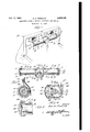
- Figure 1 is a view in perspective illustrating an electric light constructed in accordance with the present invention and showing the same mounted upon the inside of a hand bag.
- Figure 2 is a longitudinal sectional view taken substantially on the line 2-2 of Figure 1, the plane of section paralleling the longitudinal axis of the lamp base and the lamp and batteries being left in elevation.
- Figure 3 is a transverse section, on an enlarged scale taken substantially on the line 3--3 of Figure 1, looking in the direction of the arrows.
- Figure 4 is a transverse section, on an enlarged scale taken substantially on the line 4-4 of Figure 1, looking in the direction of the arrows, the lamp and movable switch element being left in elevation.
- Figure 5 is a longitudinal fragmentary section, on an enlarged scale, of one end of the device, in
- the light comprises a long, tubular casing or housing, generally designated 0, which is made up of a central switch and bulb carrying section H]; the two lateral or side sections l i, of tubular form, in which the batteries l2 are housed, and the end cap sections [3, each of which has a skirt portion 14 in which is threadedly secured the adjacent end of a lateral section as indicated at l5.
- the caps it are knurled or ribbed around the outside of the flanges or skirts as shown in Figure 1, to facilitate turning the light as hereinafter described.
- the central section while shorter than the lateral sections, is approximately tubular and at its ends, is of the same outside and inside diameter as the ends of the lateral sections to which it is joined and into which it opens.
- a neck ll Extending from the side of the central section is a neck ll, over the open outer end of which is secured, in a suitable manner, a transparent lens or bulls-eye I8.
- a slot 20 Formed in the flattened top 19, of the section Hi, is a slot 20, the length of which is directed longitudinally of the casing.
- Running lengthwise of the entire casing, that is through the central and lateral sections l0 and I I, and at the back of the casing, is a current conductor or bus bar 2
- each cap I3 Within each cap I3 is a flat metal annulus 22, against one face of which the adjacent end of the conductor abuts, for electrical connection therewith, and such annulus has as an integral part, an inwardly projecting resilient terminal 23 which is pressed against the metal casing bottom which forms one pole of the adjacent battery l2.
- a current conducting bridge 24 which, when Viewed in side elevation as in Figure 2, is U-shaped and comprises the longitudinal bar 25 and the right angularly directed, parallel legs 26.
- the bar 25 is disposed across the inner end of the neck I1 and each of the legs 26, is of the proper circular form to engage in the circular part of the central section, in position to be engaged, and electrically connected with the central terminal forming the other pole of a battery l2.
- each of the disk like legs 26, at the rear part thereof is provided with a cut-out or notch 21, see Figure 4, for the passage of the conductor bar 2
- the bar 25 has a central opening defined by an inwardly projecting sleeve 28, which is suitably formed to receive and have electric contact with the shell 29 forming one terminal of an electric incandescent lamp 30, The other, and end, terminal 31 of this lamp is directed toward, but spaced from the conductor bar 2 i A suitable reflector 32 is secured in the neck I! between the head of the lamp and the lens [8, in the conventional manner.
- a switch pin 33 Slidably lengthwise of the slot 20 is a switch pin 33 which has a button 34 on its outer end for its actuation.
- the pin 33 has fixed theretoone end of ,a resilient bowed metal switch blade 35 which has the convex side thereof disposed insliding ontact with the conductor bar 2 I, as shown in Figure 4. he other end of the blade is setat an angle to come into contact with the terminal 3
- each'section il has formed-in and around the outside thereof the channel 35, in which is engaged :a split band ring 3?, having thetwo, relatively long terminals 38 and 39.
- the terminal 39 is secured in a suitable manner to the inside ofthe receptacle H and carries one of the two partsof a snap fastener 40, the other terminal 38.-carrying;the other .part of the fastener, as shown in Figure 3.
- a snap fastener 40 the other terminal 38.-carrying;the other .part of the fastener, as shown in Figure 3.
- an elongated tubular body formed of separable interconnected end and intermediate sections, an open cylindrical neck portion projecting laterally from the center of said intermediate section, a U-shaped member of sheet metal having circular end portions interconnected by a straight central portion fitted within said intermediate section with the central portion extending across the inner open end of said neck portion, an annular flange encircling an aperture formed in the center of said central portion and constituting a socket for a lamp bulb, a reflector encircling said lamp bulb and supported within said neck portion on the base thereof, a concavo-convex lens seated over the-outer end of said neck portion, an electric cell housed within each of said end sections, a metal conductor extending through the body between the bottoms of said cells, the positive electrodes of said cells bearing against the said circular end portions of the member, caps closing the outer ends of said end sections, resilient switch element disposed in contact with said conductor, means for moving said switch element into and out of contact with the center contact of the base of the lamp bulb, and
Description
Feb. 17, 1953 G. R. FROHLICH 2,629,045
FLASHLIGHT HAVING A CENTRAL ADJUSTABLE LAMP CARRIER Filed 001 27, 1949 INVENTOR ATTORNEY Patented Feb. 17, 195.?
FLASHLIGHT HAVING A CENTRAL ADJUST- ABLE LAMP CARRIER Gus R. Frohlich, Los Angeles, Calif.
Application October 27, 1949, Serial No. 123,967
1 Claim.
This invention relates to improvements in electric hand or flash lights and a particular object of the invention is to provide a light of this kind having a long casing with the incandescent lamp in the middle portion thereof between a pair of batteries, wherein a novel and simple arrangement is provided to electrically couple one side of the lamp filament with the terminals of like polarity of the two batteries.
Another object of the invention is to provide in a device of the character stated, a novel means of providing a common conductor for the other two poles of the batteries and for establishing at will the necessary electrical connection between such conductor and the other side of the lamp filament to complete the electric circuit necessary to energize the lamp.
Still another object is to provide a novel sliding switch arrangement for opening and closing said circuit.
Yet another object is to provide a novel means for mounting a light unit within a hand bag or other receptacle whereby the light may be conveniently turned to direct the light rays in a desired direction.
Other objects and advantages will appear as the description proceeds and the invention will be best understood from a consideration of the following detailed description taken in connection with the accompanying drawing forming a part of the specification, with the understanding, however, that the invention is not to be limited to the exact details of construction shown and described since obvious modifications will occur to a person skilled in the art.
In the drawing:
Figure 1 is a view in perspective illustrating an electric light constructed in accordance with the present invention and showing the same mounted upon the inside of a hand bag.
Figure 2 is a longitudinal sectional view taken substantially on the line 2-2 of Figure 1, the plane of section paralleling the longitudinal axis of the lamp base and the lamp and batteries being left in elevation.
Figure 3 is a transverse section, on an enlarged scale taken substantially on the line 3--3 of Figure 1, looking in the direction of the arrows.
Figure 4 is a transverse section, on an enlarged scale taken substantially on the line 4-4 of Figure 1, looking in the direction of the arrows, the lamp and movable switch element being left in elevation.
Figure 5 is a longitudinal fragmentary section, on an enlarged scale, of one end of the device, in
a plane perpendicular to the section plane for Figure 2, showing details of a battery terminal connection.
Referring now more particularly to the drawing, it will be seen that one application of the invention has been shown, as being mounted upon the inside of a hand bag which is generally designated H. It is to be understood, however, that this is not the only use to which the invention may be put, as it will be readily obvious that it may be mounted in other receptacles Without departing from the spirit of the invention.
The light comprises a long, tubular casing or housing, generally designated 0, which is made up of a central switch and bulb carrying section H]; the two lateral or side sections l i, of tubular form, in which the batteries l2 are housed, and the end cap sections [3, each of which has a skirt portion 14 in which is threadedly secured the adjacent end of a lateral section as indicated at l5.
The caps it are knurled or ribbed around the outside of the flanges or skirts as shown in Figure 1, to facilitate turning the light as hereinafter described.
The central section and the lateral sections are secured together by the press fitted interengaging flanges l6 as shown in Figure 2.
As is clearly shown the central section, while shorter than the lateral sections, is approximately tubular and at its ends, is of the same outside and inside diameter as the ends of the lateral sections to which it is joined and into which it opens.
Extending from the side of the central section is a neck ll, over the open outer end of which is secured, in a suitable manner, a transparent lens or bulls-eye I8.
Formed in the flattened top 19, of the section Hi, is a slot 20, the length of which is directed longitudinally of the casing.
Running lengthwise of the entire casing, that is through the central and lateral sections l0 and I I, and at the back of the casing, is a current conductor or bus bar 2|, which is held in position by having a portion 2|, at each end, oifset and engaged in a recess Zia in the wall of the adjacent section II. Each end of this conductor projects slightly beyond the end of the adjacent section as clearly shown in Figures 2 and 5.
Within each cap I3 is a flat metal annulus 22, against one face of which the adjacent end of the conductor abuts, for electrical connection therewith, and such annulus has as an integral part, an inwardly projecting resilient terminal 23 which is pressed against the metal casing bottom which forms one pole of the adjacent battery l2.
Within the central section I is a current conducting bridge 24, which, when Viewed in side elevation as in Figure 2, is U-shaped and comprises the longitudinal bar 25 and the right angularly directed, parallel legs 26.
The bar 25 is disposed across the inner end of the neck I1 and each of the legs 26, is of the proper circular form to engage in the circular part of the central section, in position to be engaged, and electrically connected with the central terminal forming the other pole of a battery l2.
The edge of each of the disk like legs 26, at the rear part thereof is provided with a cut-out or notch 21, see Figure 4, for the passage of the conductor bar 2|.
The bar 25 has a central opening defined by an inwardly projecting sleeve 28, which is suitably formed to receive and have electric contact with the shell 29 forming one terminal of an electric incandescent lamp 30, The other, and end, terminal 31 of this lamp is directed toward, but spaced from the conductor bar 2 i A suitable reflector 32 is secured in the neck I! between the head of the lamp and the lens [8, in the conventional manner.
Slidably lengthwise of the slot 20 is a switch pin 33 which has a button 34 on its outer end for its actuation.
The pin 33 has fixed theretoone end of ,a resilient bowed metal switch blade 35 which has the convex side thereof disposed insliding ontact with the conductor bar 2 I, as shown in Figure 4. he other end of the blade is setat an angle to come into contact with the terminal 3| of the lamp when the three parts 33, 34 and 35, making up the switch, are shifted in the proper direction.
In this manner the circuit including the batteries and lamp is closed.
For the convenient mounting of the light for turning on the long axis of the casing,.each'section il has formed-in and around the outside thereof the channel 35, in which is engaged :a split band ring 3?, having thetwo, relatively long terminals 38 and 39.
The terminal 39 is secured in a suitable manner to the inside ofthe receptacle H and carries one of the two partsof a snap fastener 40, the other terminal 38.-carrying;the other .part of the fastener, as shown in Figure 3. Thus when the two terminalstfland 39 arecoupled together the band will be engaged in anannular channel and as two of the bands are employed it will be seen that the light may be readily turned. 'Ihe knurled or roughened edges of'thecaps i3, facilitate such action.
From the foregoing it will be apparent that there is provided in the present invention a light of unique construction which will greatly assist in the location of articles in a hand bag or satchel in which the light is mounted and may also be detached and used as a hand flash light when desired.
I claim:
In a flashlight, an elongated tubular body formed of separable interconnected end and intermediate sections, an open cylindrical neck portion projecting laterally from the center of said intermediate section, a U-shaped member of sheet metal having circular end portions interconnected by a straight central portion fitted within said intermediate section with the central portion extending across the inner open end of said neck portion, an annular flange encircling an aperture formed in the center of said central portion and constituting a socket for a lamp bulb, a reflector encircling said lamp bulb and supported within said neck portion on the base thereof, a concavo-convex lens seated over the-outer end of said neck portion, an electric cell housed within each of said end sections, a metal conductor extending through the body between the bottoms of said cells, the positive electrodes of said cells bearing against the said circular end portions of the member, caps closing the outer ends of said end sections, resilient switch element disposed in contact with said conductor, means for moving said switch element into and out of contact with the center contact of the base of the lamp bulb, and a bracket carried by each of said end sections to support the body in a fixed position of use, said intermediate section being slip jointed to the adjacent ends of said end sections whereby it may be turned relatively to the end sections to vary the angular direction of the light beam from said lamp bulb and the reflector.
GUS R. FROHLICH.
REFERENCES CITED The following references are of record in the file of this patent:
UNITED STATES PATENTS Number Name Date 1,763,815 Pajeau June 17, 1930 2,187,308 Fuss Jan. 16, 1940 2,198,525 Burgess Apr. 23, 1940 2,285,454 Moss June 9, 1942 2,299,148 Johnson Oct. 20, 1942 2,564,412 Von Haase Aug. 14, 1951 FOREIGN PATENTS Number Country Date 495,103 England 1938
Priority Applications (1)
| Application Number | Priority Date | Filing Date | Title |
|---|---|---|---|
| US123967A US2629045A (en) | 1949-10-27 | 1949-10-27 | Flashlight having a central adjustable lamp carrier |
Applications Claiming Priority (1)
| Application Number | Priority Date | Filing Date | Title |
|---|---|---|---|
| US123967A US2629045A (en) | 1949-10-27 | 1949-10-27 | Flashlight having a central adjustable lamp carrier |
Publications (1)
| Publication Number | Publication Date |
|---|---|
| US2629045A true US2629045A (en) | 1953-02-17 |
Family
ID=22411989
Family Applications (1)
| Application Number | Title | Priority Date | Filing Date |
|---|---|---|---|
| US123967A Expired - Lifetime US2629045A (en) | 1949-10-27 | 1949-10-27 | Flashlight having a central adjustable lamp carrier |
Country Status (1)
| Country | Link |
|---|---|
| US (1) | US2629045A (en) |
Cited By (11)
| Publication number | Priority date | Publication date | Assignee | Title |
|---|---|---|---|---|
| US2779344A (en) * | 1953-03-06 | 1957-01-29 | Hemmings | Compact construction |
| US2779444A (en) * | 1955-07-29 | 1957-01-29 | Ericsson Telefon Ab L M | Speed governor, particularly for dials |
| US2795997A (en) * | 1955-03-07 | 1957-06-18 | Irving W Allen | Illuminated viewing device |
| US2911521A (en) * | 1957-12-16 | 1959-11-03 | Ferdinand C Schetz | Illuminator for lady's handbag |
| US3321616A (en) * | 1965-01-11 | 1967-05-23 | Ronald E Adler | Illuminated sketch and memo board |
| US3381122A (en) * | 1966-03-25 | 1968-04-30 | Albert P. Boyle Jr. | Illuminated clip board |
| US3403249A (en) * | 1965-12-22 | 1968-09-24 | Union Carbide Corp | Battery powered signal unit |
| US3683168A (en) * | 1969-06-27 | 1972-08-08 | Elta Vertriebs Gmbh Tatje & Co | Illuminating spectacles for working in the dark |
| US3976871A (en) * | 1975-04-29 | 1976-08-24 | Atherton Ira W | Handbag with means for illuminating the interior thereof |
| US20040228120A1 (en) * | 2003-02-10 | 2004-11-18 | Ross Jeremy B. | Flashlight devices and accessories |
| US20060050502A1 (en) * | 2003-02-10 | 2006-03-09 | Ross Jeremy B | Multi-purpose flashlight device and method of using same |
Citations (7)
| Publication number | Priority date | Publication date | Assignee | Title |
|---|---|---|---|---|
| US1763815A (en) * | 1928-06-07 | 1930-06-17 | Toy Tinkers Inc | Flash light |
| GB495103A (en) * | 1936-02-04 | 1938-11-04 | Rene Alfred Chauvot | Improvements in or relating to portable electric lamps |
| US2187308A (en) * | 1937-12-31 | 1940-01-16 | George R Fuss | Illumination means for handbags and the like |
| US2198525A (en) * | 1937-05-01 | 1940-04-23 | Morel D Burgess | Flashlight |
| US2285454A (en) * | 1939-11-06 | 1942-06-09 | Robert A Moss | Illuminating device for handbags |
| US2299148A (en) * | 1941-08-02 | 1942-10-20 | Lawrence L Johnson | Flashlight |
| US2564412A (en) * | 1947-02-15 | 1951-08-14 | Haase Anthony Von | Flashlight having an angularly adjustable lamp carrier and hood |
-
1949
- 1949-10-27 US US123967A patent/US2629045A/en not_active Expired - Lifetime
Patent Citations (7)
| Publication number | Priority date | Publication date | Assignee | Title |
|---|---|---|---|---|
| US1763815A (en) * | 1928-06-07 | 1930-06-17 | Toy Tinkers Inc | Flash light |
| GB495103A (en) * | 1936-02-04 | 1938-11-04 | Rene Alfred Chauvot | Improvements in or relating to portable electric lamps |
| US2198525A (en) * | 1937-05-01 | 1940-04-23 | Morel D Burgess | Flashlight |
| US2187308A (en) * | 1937-12-31 | 1940-01-16 | George R Fuss | Illumination means for handbags and the like |
| US2285454A (en) * | 1939-11-06 | 1942-06-09 | Robert A Moss | Illuminating device for handbags |
| US2299148A (en) * | 1941-08-02 | 1942-10-20 | Lawrence L Johnson | Flashlight |
| US2564412A (en) * | 1947-02-15 | 1951-08-14 | Haase Anthony Von | Flashlight having an angularly adjustable lamp carrier and hood |
Cited By (13)
| Publication number | Priority date | Publication date | Assignee | Title |
|---|---|---|---|---|
| US2779344A (en) * | 1953-03-06 | 1957-01-29 | Hemmings | Compact construction |
| US2795997A (en) * | 1955-03-07 | 1957-06-18 | Irving W Allen | Illuminated viewing device |
| US2779444A (en) * | 1955-07-29 | 1957-01-29 | Ericsson Telefon Ab L M | Speed governor, particularly for dials |
| US2911521A (en) * | 1957-12-16 | 1959-11-03 | Ferdinand C Schetz | Illuminator for lady's handbag |
| US3321616A (en) * | 1965-01-11 | 1967-05-23 | Ronald E Adler | Illuminated sketch and memo board |
| US3403249A (en) * | 1965-12-22 | 1968-09-24 | Union Carbide Corp | Battery powered signal unit |
| US3381122A (en) * | 1966-03-25 | 1968-04-30 | Albert P. Boyle Jr. | Illuminated clip board |
| US3683168A (en) * | 1969-06-27 | 1972-08-08 | Elta Vertriebs Gmbh Tatje & Co | Illuminating spectacles for working in the dark |
| US3976871A (en) * | 1975-04-29 | 1976-08-24 | Atherton Ira W | Handbag with means for illuminating the interior thereof |
| US20040228120A1 (en) * | 2003-02-10 | 2004-11-18 | Ross Jeremy B. | Flashlight devices and accessories |
| US20060050502A1 (en) * | 2003-02-10 | 2006-03-09 | Ross Jeremy B | Multi-purpose flashlight device and method of using same |
| US7172311B2 (en) | 2003-02-10 | 2007-02-06 | First-Light Usa, Llc | Flashlight devices and accessories |
| US7303306B2 (en) | 2003-02-10 | 2007-12-04 | First-Light Usa, Llc | Multi-purpose flashlight device and method of using same |
Similar Documents
| Publication | Publication Date | Title |
|---|---|---|
| US2581129A (en) | Portable electric flashlight with retractable mount for auxiliary lamps | |
| US3030497A (en) | Electric lanterns or torches | |
| US4244011A (en) | Rechargeable flashlight | |
| US3393312A (en) | Adjustable flashlight | |
| US2629045A (en) | Flashlight having a central adjustable lamp carrier | |
| US2401366A (en) | Portable electric flashlight | |
| US2879381A (en) | Flashlights | |
| US3345508A (en) | Flashlight formed of two molded parts | |
| US5122938A (en) | Twist switch for flashlight | |
| US3124306A (en) | Figure | |
| US2299148A (en) | Flashlight | |
| US3014125A (en) | Switching mechanism for flashlights and the like | |
| US2483820A (en) | Flashlight | |
| US3175080A (en) | Flashlight | |
| US2443539A (en) | Flashlight switch | |
| US2412313A (en) | Pocket flashlight | |
| US2538332A (en) | Flashlight | |
| US3003057A (en) | Portable electric lanterns or torches and switching devices therefor | |
| US3226538A (en) | Illuminating means | |
| US3835309A (en) | Electrical appliance powered by self-contained rechargeable battery | |
| US2915744A (en) | Flashlights | |
| US1671744A (en) | Flash light | |
| US2528701A (en) | Vest pocket flashlight | |
| US1408526A (en) | Pocket flash light | |
| US2727981A (en) | Electric torch with auxiliary outlet |