US20120053418A1 - Endoscopic form detection device and form detecting method of insertion section of endoscope - Google Patents
Endoscopic form detection device and form detecting method of insertion section of endoscope Download PDFInfo
- Publication number
- US20120053418A1 US20120053418A1 US13/229,182 US201113229182A US2012053418A1 US 20120053418 A1 US20120053418 A1 US 20120053418A1 US 201113229182 A US201113229182 A US 201113229182A US 2012053418 A1 US2012053418 A1 US 2012053418A1
- Authority
- US
- United States
- Prior art keywords
- interpolation
- section
- curve
- link
- arc
- Prior art date
- Legal status (The legal status is an assumption and is not a legal conclusion. Google has not performed a legal analysis and makes no representation as to the accuracy of the status listed.)
- Granted
Links
Images
Classifications
-
- A—HUMAN NECESSITIES
- A61—MEDICAL OR VETERINARY SCIENCE; HYGIENE
- A61B—DIAGNOSIS; SURGERY; IDENTIFICATION
- A61B1/00—Instruments for performing medical examinations of the interior of cavities or tubes of the body by visual or photographical inspection, e.g. endoscopes; Illuminating arrangements therefor
- A61B1/00147—Holding or positioning arrangements
Definitions
- the present invention relates to an endoscopic form detection device including an endoscope configured to be inserted into a body cavity and a form detecting method of an inserting section of the endoscope.
- Jpn. Pat. Appln. KOKAI Publication No. 2000-175862 discloses an endoscope insertion form detection device including source coils disposed to an inserting section of an endoscope configured to be inserted into a body cavity.
- positions of the respective source coils are detected by a sense coil provided outside a body. Further, based on the detected positions of the source coils, a form of the inserting section of the endoscope is detected.
- Jpn. Pat. Appln. KOKAI Publication No. 2007-319622 discloses an endoscope device including two sensors disposed to an inserting section of an endoscope.
- a sensor on a proximal end side is determined as a reference, and a position and a posture of a sensor on a distal end side are detected.
- the sensor on the proximal end side is arranged near a proximal end of a bending section, and the sensor on the distal end side is arranged at a distal-end hard section.
- a bending angle and a bending direction of the bending section are calculated by detecting the position and the posture of the sensor on the distal end side with respect to the sensor on the proximal end side.
- Jpn. Pat. Appln. KOKAI Publication No. 11-19027 discloses an endoscopic form detection device including gyroscopes disposed to an inserting section of an endoscope.
- a posture in a predetermined region (a region to which the gyroscope is disposed) of the inserting section of the endoscope is detected by the gyroscope.
- a form of the inserting section is detected based on the detected posture in the predetermined region.
- an endoscopic form detection device includes that an endoscope including an inserting section in which sensor units are arranged in longitudinal directions at intervals of a predetermined inter-sensor dimension; a posture detecting section configured to detect a posture of each of the sensor units based on measurement data in the sensor unit; a linear form detecting section configured to detect a detected linear form of the inserting section of the endoscope on an assumption that a form between the respective sensor units is a linear link whose dimension is equal to the inter-sensor dimension based on the posture of each of the sensor units detected by the posture detecting section; and a curve form detecting section configured to perform curve interpolation with respect to the detected linear form detected by the linear form detecting section on an assumption that a form between the respective sensor units is an arc whose arc length is equal to the inter-sensor dimension, and configured to detect a detected curve form.
- a form detecting method of an inserting section of an endoscope includes that performing measurement by using sensor units arranged in the inserting section of the endoscope in longitudinal directions at intervals of a predetermined inter-sensor dimension; detecting a posture of each sensor unit by using a posture detecting section based on measurement data in the sensor unit; detecting a detected linear form of the inserting section of the endoscope by using a linear form detecting section on the assumption that a form between the respective sensor units is a linear link whose dimension is equal to the inter-sensor dimension based on the posture of each sensor unit detected by the posture detecting section; and performing curve interpolation with respect to the detected linear form detected by the linear form detecting section and forming a detected curve form by using a curve form detecting section on the assumption that a form between the respective sensor units is an arc whose arc length is equal to the inter-sensor dimension.
- FIG. 1 is a block diagram showing a configuration of an endoscopic form detection device according to a first embodiment of the present invention
- FIG. 2 is a schematic view showing a configuration of an inserting section of an endoscope according to the first embodiment
- FIG. 3 is a block diagram showing a configuration of a personal computer of the endoscopic form detection device according to the first embodiment
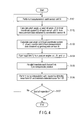
- FIG. 4 is a flowchart showing a method of detecting a form of the inserting section of the endoscope in a stationary state according to the first embodiment
- FIG. 5 is a schematic view showing a global coordinate system and a corrected coordinate system of the endoscopic form detection device according to the first embodiment in comparison to each other;
- FIG. 6 is a schematic view showing a detected linear form detected by a linear form detecting section of the endoscopic form detection device according to the first embodiment
- FIG. 7 is a schematic view explaining processing in a link position compensating section of the linear form detecting section according to the first embodiment
- FIG. 8 is a schematic view showing a detected curve form detected by a curve form detecting section of the endoscopic form detection device according to the first embodiment
- FIG. 9 is a flowchart showing a method of detecting the detected curve form by the curve form detecting section according to the first embodiment
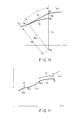
- FIG. 10 is a schematic view explaining processing in a curve interpolating section of the curve form detecting section according to the first embodiment
- FIG. 11 is a schematic view explaining processing in an arc position compensating section of the curve form detecting section according to the first embodiment
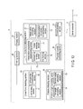
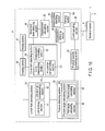
- FIG. 12 is a block diagram showing a configuration of a personal computer of an endoscopic form detection device according to a second embodiment of to the present invention.
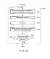
- FIG. 13 is a flowchart showing a method of detecting a detected curve form by the curve form detecting section of the endoscopic form detection device according to the second embodiment
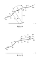
- FIG. 14 is a schematic view explaining processing in an interpolation sequentially implementing section of the curve form detecting section according to the second embodiment
- FIG. 15 is a schematic view explaining processing in an uninterpolated link position compensating section of the curve form detecting section according to the second embodiment
- FIG. 16 is a block diagram showing a configuration of a personal computer of an endoscopic form detection device according to a first modification of the present invention.
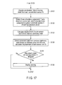
- FIG. 17 is a flowchart showing a method of detecting a form of an inserting section of an endoscope in a moving state according to the first modification.
- FIG. 1 to FIG. 15 A first embodiment according to the present invention will now be described with reference to FIG. 1 to FIG. 15 .
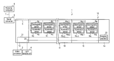
- FIG. 1 is a view showing an endoscopic form detection device 1 according to a first embodiment.
- an endoscope 10 of the endoscopic form detection device 1 includes an inserting section 11 configured to be inserted into a body cavity and an operating section 12 provided to a proximal end side of the inserting section 11 .
- the inserting section 11 includes a distal-end hard section 14 provided at a most distal end side; a bending section 16 provided to the proximal end side of the distal-end hard section 14 , and an elongated flexible tube section 18 provided to the proximal end side of the bending section 16 .
- An imaging element 20 such as a CCD configured to image a subject is provided in the distal-end hard section 14 .
- One end of an imaging signal line 21 is connected to the imaging element 20 .
- the imaging signal line 21 is extended to the outside of the endoscope 10 from the operating section 12 through the inserting section 11 , and the other end of the imaging signal line 21 is connected to a video processor 3 which is an image processing unit.
- a light guide 23 configured to guide illumination light applied to a subject is extended to an illumination window (not shown) of the distal-end hard section 14 along longitudinal directions in the inserting section 11 .
- the light guide 23 is extended to the outside of the endoscope 10 from the operating section 12 and connected to a light source unit 4 .
- each of four bending operation wires (not shown) as bending operation transmission members is connected to a distal end portion of the bending section 16 in the inserting section 11 .
- the other end of each bending operation wire is connected to a bending operation knob (not shown), which is a bending operating section provided to the operating section 12 , through the flexible tube section 18 .
- the bending operation wires move in the longitudinal directions by operations using the bending operation knob.
- the bending section 16 is configured to bend in up-down directions and left-right directions of the endoscope 10 by the movement of the bending operation wires.
- a plurality of (N+1 in this embodiment) sensor units S 0 to S N are provided in the inserting section 2 .
- the sensor unit S 0 provided on a most proximal end side is arranged in a proximal end portion of the flexible tube section 18
- the sensor unit S N provided on the most distal end side is arranged in the distal end portion of the bending section 16 .
- Each sensor unit S i includes an accelerator sensor A i configured to measure acceleration, and a geomagnetic sensor B i configured to measure earth magnetism.
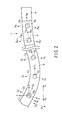
- FIG. 2 is a view showing the inserting section 11 of the endoscope 10 .
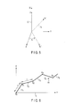
- each sensor unit S i has a local coordinate system C i (indicated by a dotted line in FIG. 2 ) having an origin at the center of the sensor unit S i , and also having an X i axis, a Y i axis, and a Z i axis.
- the X i axis directions coincide with the left-right directions of the endoscope 10 at the center of the sensor unit S i
- a right direction of the endoscope 10 as seen from the proximal end side is determined to be positive.
- the Y i axis directions coincide with the longitudinal directions at the center of the sensor unit S i , and the distal end side direction is determined to be positive.
- the Z i axis directions coincide with the up-down directions of the endoscope 10 at the center of the sensor unit S i , and an up direction of the endoscope 10 is determined to be positive.
- the acceleration sensor A i is configured to measure an X i axis directions component, a Y i axis directions component, and a Z i axis directions component of acceleration at the origin of the local coordinate system C i .
- a global coordinate system C (indicated by a solid line in FIG. 2 ) having an X axis, a Y axis, and a Z axis is defined with the center of the sensor unit S 0 provided on the most proximal end side being determined as an origin.
- the global coordinate system C is a rectangular Cartesian coordinate system for a right-hand system with the center of the sensor unit S 0 provided on the most proximal end side determined as an origin.
- the X-axis directions coincide with predetermined directions (directions parallel to arrows D 1 and D 2 in FIG. 2 in this embodiment) perpendicular to vertical directions in which gravity functions, and a direction of the arrow D 1 in FIG.
- the Y axis directions coincide with directions (directions parallel to arrows E 1 and E 2 in FIG. 2 in this embodiment) perpendicular to the vertical directions and the X axis directions, and a direction of the arrow E 1 in FIG. 2 is determined to be positive.
- the Z axis directions coincide with the vertical directions, and an up direction (direction extending from a back side to a front side of a paper sheet) of the vertical directions is determined to be positive. It is to be noted that a positive direction of the X axis directions of the global coordinate system is determined as a magnetic north direction for convenience of explanation.
- Each local coordinate system C i is a coordinate system obtained by rotating the global coordinate system C ⁇ i about the X axis, ⁇ i about the Y axis, and ⁇ i about the Z axis and parallel translating the origin from the center of the sensor unit S 0 provided on the most proximal end side to the center of the sensor unit S i .
- ⁇ i is referred to as a pitch angle
- ⁇ i is referred to as a roll angle
- ⁇ i is referred to as a yaw angle
- three angles, i.e., the pitch angle ⁇ i , the roll angle ⁇ i , and the yaw angle ⁇ i will be generically referred to as posture angles.
- a clockwise direction of each posture angle ⁇ i , ⁇ i , or ⁇ i seen from a negative direction of each of the X axis, the Y axis, and the Z axis is determined to be positive.
- a posture of the sensor unit S i can be detected by calculating values of the posture angles ⁇ i , ⁇ i , and ⁇ i .
- a serial bus 5 such as 12 C is connected to the acceleration sensor A i and the geomagnetic sensor B i of each sensor unit S i .
- the serial bus 5 is extended to the outside of the endoscope 10 from the operating section 12 through the inside of the inserting section 11 , and its proximal end is connected to a serial converter 6 .
- the serial converter 6 is configured to convert a serial signal of measurement data input from each sensor unit S i through the serial bus 5 into a USB signal.
- One end of a USB cable 7 is connected to the serial converter 6 .
- the other end of the USB cable 7 is connected to a personal computer 8 .
- the USB signal of the measurement data in each sensor unit S i is configured to be input to the personal computer 8 from the serial converter 6 .
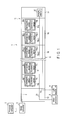
- FIG. 3 is a view showing a configuration of the personal computer 8 .
- the personal computer 8 includes a communicating section 26 connected to the serial converter 6 through the USB cable 7 .
- the communicating section 26 is configured to receive the measurement data in each sensor unit S i .
- a physical quantity converting section 28 is connected to the communicating section 26 .
- the physical quantity converting section 28 is configured to convert the measurement data in each sensor unit S i received by a communicating section 26 into a physical quantity by using an offset, a gain, and others.
- a posture detecting section 30 is connected to the physical quantity converting section 28 .
- the posture detecting section 30 is configured to detect a posture of each sensor unit S i based on the measurement data in each sensor unit S i .
- the posture detecting section 30 includes a posture angle calculating section 32 configured to calculate the three posture angles ⁇ i , ⁇ i , and ⁇ i as rotational angles in the local coordinate system C i of each sensor unit S i about the X axis, the Y axis, and the Z axis from the global coordinate system C based on measurement data obtained by the acceleration sensor A i and the geomagnetic sensor B i of each sensor unit S i .
- the posture angle calculating section 32 includes a first angle calculating section 34 configured to calculate a pitch angle ⁇ i as a rotational angle in the local coordinate system C i of each sensor unit S i about the X axis from the global coordinate system C and a roll angle ⁇ i as a rotational angle in the local coordinate system C i of each sensor unit S i about the Y axis from the global coordinate system C based on measurement data in the acceleration sensor A i and the geomagnetic sensor B i of each sensor unit S i .
- the posture angle calculating section 32 also includes a second angle calculating section 36 configured to calculate a yaw angle ⁇ i as a rotational angle in the local coordinate system C i of each sensor unit S i about the Z axis from the global coordinate system C based on the geomagnetic data in the geomagnetic sensor B i of each sensor unit S i .
- FIG. 4 is a flowchart showing a form detecting method of the inserting section 11 in a stationary state in which the inserting section 11 of the endoscope 10 is stopped.
- each sensor unit S i first performs measurement (a step S 101 ), and the posture detecting section 30 acquires measurement data in each sensor unit S i .
- the posture angle calculating section 32 calculates the three posture angles ⁇ i , ⁇ i , and ⁇ i in the local coordinate system C i of each sensor unit S i .
- the first angle calculating section 34 first calculates the pitch angle ⁇ i and the roll angle ⁇ i in the local coordinate system C i of each sensor unit S i (a step S 102 ) based on the measurement data in the acceleration sensor A i of each sensor unit S i .
- the posture angles ⁇ i , ⁇ i , and ⁇ i are determined as a (Z, X, Y) type that rotates in the order of the yaw angle ⁇ i , the pitch angle ⁇ i , and the roll angle ⁇ i . Therefore, a rotation matrix from the global coordinate system C to the local coordinate system C i is as follows:
- an X axis directions component, a Y axis directions component, and a Z axis directions component of an acceleration vector in the global coordinate system C are as follows:
- an X i axis directions component, a Y i axis directions component, and a Z i axis directions component of an acceleration vector in the local coordinate system C i measured by the acceleration sensor Ai are as follows:
- the local coordinate system C i is a coordinate system obtained by rotating the global coordinate system C in the order of the yaw angle ⁇ i , the pitch angle ⁇ i , and the roll angle ⁇ i . Therefore, based on Expression (1) to Expression (3), acceleration components observed in the local coordinate system C i are as follows:
- ⁇ i tan - 1 ( - a Bi ⁇ ⁇ _ ⁇ ⁇ Y a Bi ⁇ ⁇ _ ⁇ ⁇ X 2 + a Bi ⁇ ⁇ _ ⁇ ⁇ Z 2 ) ( 7 )
- ⁇ i tan - 1 ⁇ ( - a Bi ⁇ ⁇ _ ⁇ ⁇ X a Bi ⁇ ⁇ _ ⁇ ⁇ Z ) ( 8 )
- the roll angle ⁇ i in the local coordinate system C i can be derived. As described above, based on measurement data in each acceleration sensor A i , the pitch angle ⁇ i and the roll angle ⁇ i in the local coordinate system C i can be calculated.
- the second angle calculating section 36 calculates the yaw angle ⁇ i in the local coordinate system C i of each sensor unit Si based on measurement data obtained by the geomagnetic sensor B i of each sensor unit S i (a step S 103 ).
- a corrected coordinate system C′ i obtained by correcting the rotation from the global coordinate system C about the X axis and the rotation from the global coordinate system C about the Y axis in each local coordinate system C i is defined by using the pitch angle ⁇ i and the roll angle ⁇ i calculated at the step S 102 .
- FIG. 5 is a view showing the global coordinate system C (indicated by a solid line in FIG.
- the corrected coordinate system C′ i obtained by correcting the rotation about the X axis and the rotation about the Y axis is a coordinate system obtained by rotating the global coordinate system C by the yaw angle ⁇ i about the Z axis and has an X′ i axis, a Y′ i axis, and a Z′ i axis.
- X′ i directions and Y′ i axis directions coincide with directions rotated by the yaw angle ⁇ i about the Z axis from the X axis directions and the Y axis directions in the global coordinate system C, respectively.
- Z′ i axis directions coincide with the vertical directions, i.e., the Z axis directions in the global coordinate system C.
- a positive direction of the X′ i directions is a direction rotated by the yaw angle ⁇ i about the Z axis from the magnetic north direction.
- an X i axis directions component, a Y i axis directions component, and a Z i axis directions component of a geomagnetic vector in the local coordinate system C i measured by the geomagnetic sensor B i are as follows:
- the corrected coordinate system C′ i is a coordinate system obtained by correcting the rotation from the global coordinate system C about the X axis and the rotation from the global coordinate system C about the Y axis in the local coordinate system C i . Therefore, based on R xi and R yi in Expression (1) and Expression (9), an X′ i axis directions component, a Y′ i axis directions component, and a Z′ i axis directions component in the corrected coordinate system C′ i of a geomagnetic vector measured by the geomagnetic sensor B i are as follows:
- M Xi ′ M Xi cos ⁇ i +M Zi sin ⁇ i (11.1)
- a geomagnetic component on a horizontal plane (an X′ i -Y′ i plane in the corrected coordinate system C′ i ) perpendicular to the vertical directions directs the magnetic north direction. Therefore, based on Expression (11.2) and Expression (11.2), an angle ⁇ i from the X′ i axis to the magnetic north direction can be obtained by using the X′ i axis component and the Y′ i axis component of the geomagnetic vector in the corrected coordinate system C′ i . That is, the following expression can be obtained:
- the corrected coordinate system C′ i is a coordinate system obtained by rotating the global coordinate system C the yaw angle ⁇ i about the Z axis. Therefore, the angle ⁇ i obtained based on Expression (12) is the yaw angle ⁇ i in the local coordinate system C i when the global coordinate system C is determined as a reference.
- the X axis directions component, the Y axis directions component, and the Z axis directions component of the geomagnetic vector in the global coordinate system C can be obtained by using a geomagnetic sensor which is of the same type as the geomagnetic sensor B i to conduct the measurement in a state in which the X axis directions, the Y axis directions, and the Z axis directions in the global coordinate system C coincide with axis directions. Further, based on Expression (13), an angle ⁇ from the X axis to the magnetic north direction is obtained by using the X axis component and the Y axis component of the geomagnetic vector in the global coordinate system C. That is, the following expression can be acquired:
- the corrected coordinate system C′ i is a coordinate system obtained by rotating the global coordinate system C by the yaw angle ⁇ i about the Z axis. Therefore, based on Expression (12) and Expression (14), the following representation can be achieved:
- the posture detecting section 30 is configured to detect a posture of each sensor unit S i .
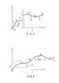
- FIG. 6 is a view showing a detected linear form 71 of the inserting section 11 of the endoscope 10 detected by the linear form detecting section 40 from the positive direction of the Z axis in the global coordinate C.
- the linear form detecting section 40 includes a link forming section 41 configured to form each link T j , and a link position compensating section 42 configured to parallel translate each link T j formed by the link forming section 41 to compensate a position of the link T j .
- the link position compensating section 42 is configured to parallel translate each link T j in such a manner that link boundaries between the link T j and adjacent links T j ⁇ 1 and T j+1 become continuous.
- a drawing section 45 is connected to the linear form detecting section 40 .
- a display section 47 is connected to the drawing section 45 .
- the detected linear form 71 of the inserting section 11 in the global coordinate system C detected by the linear form detecting section 40 is configured to be drawn by the drawing section 45 .
- An operator can confirm the detected linear form 71 drawn by the drawing section 45 in the display section 47 .
- the link forming section 41 first forms each link T j having the linear form based on the values of the posture angles ⁇ i , ⁇ i , and ⁇ i calculated at the steps S 102 and S 103 (a step S 104 ).
- a step S 104 description will be given as to formation of a kth link T k from the proximal end side between a kth sensor unit S k ⁇ 1 from the proximal end side and a (k+1)th sensor unit S k from the proximal end side.
- posture angles ⁇ k ⁇ 1 , ⁇ k ⁇ 1 , and ⁇ k ⁇ 1 in a local coordinate system C k ⁇ 1 are calculated at the steps S 102 and S 103 .
- Each of the posture angles ⁇ k ⁇ 1 , ⁇ k ⁇ 1 , and ⁇ k ⁇ 1 and the inter-sensor dimension l which is between each of the sensor units S i can be used to obtain a coordinate P′ k (l xk , l yk , l zk ) of the sensor unit S k when the sensor unit S k ⁇ 1 is placed at the origin of the global coordinate system C.
- the coordinate P′ k is represented as follows:
- e yk ⁇ 1 is a unit vector in Y k ⁇ 1 axis directions which are the longitudinal directions at the origin of the local coordinate system C k ⁇ 1 .
- a rotation matrix calculated by Expression (1) an X axis directions component, a Y axis directions component, and a Z axis directions component of the unit vector e yk ⁇ 1 in the global coordinate system C can be calculated, respectively.
- l xk , l yk , and l zk are components obtained by dividing a vector having a magnitude l in the Y k ⁇ 1 axis directions in the local coordinate system C k ⁇ 1 to the X axis directions, the Y axis directions, and the Z axis directions in the global coordinate system C, respectively.
- the link T k is formed by linearly connecting the origin of the global coordinate system C with the coordinate P′ k (l xk , l yk , l zk ) calculated by Expression (16.1) and Expression (16.2).
- each link T j other than the link T k is likewise formed by the link forming section 41 . That is, Expression (16.1) and Expression (16.2) are used to obtain a coordinate P′ j (l xj , l yj , l zj ) of the sensor unit S j on the distal end side (the side far from the origin of the global coordinate system C) of the link T j when the sensor unit S j ⁇ 1 on the proximal end side (the side close to the origin of the global coordinate system C) of the link T j is placed at the origin of the global coordinate system C.
- the link T j is formed by linearly connecting the origin of the global coordinate system C to the coordinate P′ j (l xj , l yj , l zj ). That is, the link forming section 41 is configured to form the link T j on the assumption that the link T j is extended in the longitudinal directions at the center of the sensor unit S j ⁇ 1 on the proximal end side from the center of the sensor unit S j ⁇ 1 on the proximal end side (the side close to the origin of the global coordinate system C) to the center of the sensor unit S j on the distal end side (the side far from the origin of the global coordinate system C).
- the inter-sensor dimension l is approximately 50 mm.
- the inter-sensor dimension l is increased, the number of the sensor units S i is reduced, thereby decreasing a cost.
- the inter-sensor dimension l is smaller than approximately 50 mm, an error when detecting a form of the inserting section 11 can be reduced even if the interval between the respective sensor units S i is assumed to be the linear link T j whose dimension is equal to the inter-sensor dimension l.
- the link position compensating section 42 is configured to correct a position of the link T j by parallel translating each link T j formed by the link forming section 41 in such a manner that link boundaries between the link T j and adjacent links T j ⁇ 1 and T j+1 become continuous (a step S 105 ).
- FIG. 7 is a view explaining processing in the link position compensating section 42 .
- description will be given as to positional compensation of the kth link T k from the proximal end side between the kth sensor unit S k ⁇ 1 from the proximal end side and the (k+1)th sensor unit S k from the proximal end side.
- the link position compensating section 42 parallel translates the link T k a distance from the origin to the distal end of the link positional compensation completed portion 73 . That is, the link T k is parallel translated from a position indicated by a dotted line in FIG. 7 to a position indicated by a solid line in FIG. 7 . As a result, a link boundary between the link T k ⁇ 1 and the link T k becomes continuous, and the position of the link T k is thereby compensated.
- a position of each link T j other than the link T k is likewise compensated. That is, when performing the positional compensation of the link T j , the link position compensating section 42 is configured to parallel translate the link T j a distance from the origin to the distal end (the end on the side far from the origin of the global coordinate system C) of the link positional compensation completed portion 73 . As a result, a link boundary between the link T j and a link T j ⁇ 1 adjacent to the proximal end side (the side close to the origin of the global coordinate system C) of the link T j becomes continuous, and a position of the link T j is thereby compensated. However, a position of a link T l is not compensated since a proximal end of the link T l is the origin of the global coordinate system C.
- FIG. 8 is a view showing a detected curve form 65 of the inserting section 11 of the endoscope 10 detected by the curve form detecting section 50 from a positive direction of the Z axis of the global coordinate system C.
- the detected curve form 65 is formed by performing the curve interpolation.
- a kth arc L k from the proximal end side is an arc between a kth sensor unit S k ⁇ 1 from the proximal end side and a (k+1)th sensor unit S k from the proximal end side.
- the curve form detecting section 50 includes a curve interpolating section 51 configured to perform the curve interpolation in accordance with each link T j to form the arc L j , an interpolation controlling section 52 configured to control the curve interpolating section 51 to perform the curve interpolation with respect to all the links T j , and an arc position compensating section 53 configured to parallel translate each arc L j formed by the curve interpolating section 51 to compensate a position of the arc L j .
- the arc position compensating section 53 is configured to translate each arc L j in such a manner that arc boundaries between the arc L j and adjacent arcs L j ⁇ 1 and L j+1 become continuous.
- the curve interpolating section 51 includes a normal line forming section 55 , a center deciding section 57 , and an arc forming section 59 . Details of the normal line forming section 55 , the center deciding section 57 , and the arc forming section 59 will be described later.
- the drawing section 45 is connected to the curve form detecting section 50 .
- the detected curve form 65 of the inserting section 11 in the global coordinate system C formed by the curve form detecting section 50 is drawn by the drawing section 45 .
- An operator can confirm the detected curve form 65 drawn by the drawing section 45 in the display section 47 .
- the curve form detecting section 50 is configured to carry out the curve interpolation of the detected linear form 61 on the assumption that a form between the respective sensor units S i is the arc L j whose arc length is equal to the inter-sensor dimension l, and configured to estimate the detected curve form 65 (a step S 106 ).
- the inter-sensor dimension l is smaller than approximately 50 mm, the error in the detection of the form of the inserting section 11 is small even though the portion between the respective sensor units S i is the linear link T j whose dimension is equal to the inter-sensor dimension l.
- a form of the inserting section 11 of the endoscope 10 when inserted into a body cavity is a curve form. Therefore, it is important to perform the curve interpolation of the detected linear form 61 .
- the inserting section 11 of the endoscope 10 has appropriate elasticity. Therefore, a curvature of the curved form of the inserting section 11 varies only slightly.
- the curve interpolating section 51 When performing the curve interpolation of the detected linear form 61 to detect the detected curve form 65 , the curve interpolating section 51 is configured to carry out the curve interpolation in accordance with each link T j to form the arc L j .
- a method of performing the curve interpolation of the link T j by the curve interpolating section 51 will be explained.
- description will be given as to the curve interpolation of a kth link T k from the proximal end side between a kth sensor unit S k ⁇ 1 from the proximal end side and a (k+1)th sensor unit S k from the proximal end side.
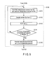
- FIG. 9 is a flowchart showing a method of using the curve form detecting section 50 to detect the detected curve form 65 from the detected linear form 61 .
- FIG. 10 is a view explaining processing in the curve interpolating section 51 . As shown in FIG. 10 , in a state before the curve interpolation of the link (an interpolation target link) T k as an interpolation target is carried out by the curve interpolating section 51 , the sensor unit S k is placed at a point Q′ k . As shown in FIG. 9 and FIG.
- the normal line forming section 55 is configured to first form a first interpolation normal line N k ⁇ 1 that runs through a proximal end (a first end point) of the link T k and is perpendicular to the link T k and a second interpolation normal line N k that runs through a distal end (a second end point) of the link T k and is perpendicular to a link (an interpolation target adjacent link) T k+1 adjacent to the distal end side of the link T k (a step S 111 ).
- the first interpolation normal line N k ⁇ 1 can be obtained under conditions that it is perpendicular to a directional vector of the link T k and that it runs through the sensor unit (the first endpoint) S k ⁇ 1 .
- the second interpolation normal line N k can be obtained under conditions that it is perpendicular to a directional vector of the link T k+1 and that it runs through the sensor unit (a second end point) S k .
- the center deciding section 57 is configured to calculate an intersection O k of the first interpolation normal line N k ⁇ 1 and the second interpolation normal line N k and to decide the intersection O k as the center of an arc L k (a step S 112 ). If the first interpolation normal line N k ⁇ 1 and the second interpolation normal line N k do not cross each other, an intermediate point O k of two points that minimize a distance between the first interpolation normal line N k ⁇ 1 and the second interpolation normal line N k is calculated.
- an equation of a straight line (not shown) perpendicular to both the first interpolation normal line N k ⁇ 1 and the second interpolation normal line N k is first obtained. Further, an intersection of this straight line and the first interpolation normal line N k ⁇ 1 and an intersection of this straight line and the second interpolation normal line N k are obtained, and an intermediate point of the two intersections is the intermediate point O k . Moreover, the intermediate point O k is determined as the center O k of the arc L k (a step S 112 ).
- the arc forming section 59 is configured to form the arc L k (a step S 113 ).
- the arc L k has a radius R k equal to a distance between the center O k decided by the center deciding section 57 and the proximal end (the first end point) of the link (the interpolation target link) T k . That is, the arc L k has curvature 1 /R k .
- the ark L k is the arc L k whose arc length starting from the proximal end (the first end point) of the link T k is equal to the inter-sensor dimension l.
- a distal end Q k of the arc L k is a position of the sensor unit S k after the curve interpolation. That is, the position of the sensor unit S k moves from the point Q′ k to the point Q k by the curve interpolation of the link T k . As described above, the curve interpolation of the link T k is performed.
- the curve interpolation is likewise carried out with respect to each link T j other than the link T k by the curve interpolating section 51 . That is, when performing the curve interpolation of the link (an interpolation target link) T j , the normal line forming section 55 is configured to form a first interpolation normal line N j ⁇ 1 that runs through a first end point which is a proximal end (an end on a side close to the origin of the global coordinate C) of the link T j and is perpendicular to the link T j and a second interpolation normal line N j that runs through a second end point which is a distal end (an end on a side far from the origin of the global coordinate C) of the link T j and is perpendicular to a link (an interpolation target adjacent link) T j+1 adjacent to the distal end side (the side far from the origin of the global coordinate C) of the link T j (the step S 111 ).
- the center deciding section 57 is configured to calculate an intersection O j of the first interpolation normal line N j ⁇ 1 and the second interpolation normal line N j or an intermediate point O j of two points that minimize a distance between the first interpolation normal line N j ⁇ 1 and the second interpolation normal line N j , and configured to decide the intersection O j or the intermediate point O j as the center O j of an arc L j (the step S 112 ).
- the arc forming section 59 is configured to form the arc L j whose radium R j is equal to a distance between the center O j and the proximal end of the link (the interpolation target link) T j and whose arc length starting from the proximal end of the link T j is equal to the inter-sensor dimension l (the step S 113 ).
- the interpolation controlling section 52 is configured to confirm whether the curve interpolation has been completed with regard to all the links T j (a step S 114 ).
- the processing advances to the next step (the step S 114 -Yes).
- the processing returns to the step S 111 (the step S 114 -No), and the curve interpolating section 51 is configured to perform the curve interpolation with respect to the links T j which have not been subjected to the curve interpolation. That is, the curve interpolating section 51 is configured to be controlled to carry out the steps S 111 to S 113 until the curve interpolation is completed with respect to all the links T j (N links in this embodiment).
- each arc L j formed by the curve interpolating section 51 is parallel translated by the arc position compensating section 53 in such a manner that arc boundaries between the arc L j and adjacent arcs L j ⁇ 1 and L j+1 become continuous, thereby compensating a position of the arc L j (a step S 115 ).
- FIG. 11 is a view explaining processing in the arc position compensating section 53 .
- the arc position compensating section 53 is configured to parallel translate the arc L k a distance from the proximal end of the arc L k before the positional compensation to the distal end of the arc position compensation completed portion 67 . That is, the arc L k is parallel translated from a position indicated by a dotted line in FIG. 11 to a position indicated by a solid line in FIG. 11 . As a result, an arc boundary between the arc L k ⁇ 1 and the arc L k becomes continuous, and the position of the arc L k is compensated.
- a position of each arc L j other than the arc L k is also compensated by the arc position compensating section 53 . That is, when performing the positional compensation of the arc L j , the arc position compensating section 53 is configured to parallel translate the arc L j a distance from a proximal end of the arc L j before the positional compensation to the distal end (the end on the side far from the origin of the global coordinate system C) of the arc position compensation completed portion 67 .
- an arc boundary between the arc L j and an arc L j ⁇ 1 adjacent to the proximal end side (the side close to the origin of the global coordinate system C) of the arc L j becomes continuous, and the position of the arc L j is compensated.
- the positional compensation is not performed.
- step S 107 when the curve interpolation of the detected linear form 61 by the curve form detecting section 50 is completed and the detected curve form 65 is formed, whether inspection by the endoscopic form detection device 1 has been completed is confirmed (a step S 107 ).
- the processing returns to the step S 101 to detect a form of the inserting section 11 of the endoscope 10 in the next stationary state.
- the step S 107 -Yes the form detection of the inserting section 11 of the endoscope 10 is finished.
- the endoscopic form detection device 1 and the form detecting method of the inserting section 11 of the endoscope 10 using the endoscopic form detection device 1 exercise the following effect. That is, in the endoscopic form detection device 1 , a posture detecting section 30 is configured to detect a posture of each sensor unit S i from measurement data of the sensor unit S i , and the linear form detecting section 40 is configured to detect the detected linear form 61 of the inserting section 11 of the endoscope 10 from the posture of each sensor unit S i . Furthermore, the curve form detecting section 50 is configured to carry out the curve interpolation of the detected linear form 61 to detect the detected linear form 65 .
- the detected linear form 65 of the inserting section 11 is detected from the measurement data of each sensor unit S i arranged in the inserting section 11 configured to be inserted in a body cavity at the time of observation, a sense coil and others do not have to be provided outside a body. Therefore, miniaturization and simplification of the endoscopic form detection device 1 can be realized.
- the curve form detecting section 50 is configured to perform the curve interpolation of the detected linear form 61 on the assumption that a form between the respective sensor units S i is the arc L j whose arc length is equal to the inter-sensor dimension l, and configured to detect the detected curve form 65 .
- the inserting section 11 of the endoscope 10 has appropriate elasticity. Therefore, a curvature of the curved form of the inserting section 11 varies only slightly.
- an acceleration sensor A i is configured to measure gravitational acceleration and a geomagnetic sensor B i is configured to measure geomagnetism in the stationary state in which the inserting section 11 is not moving.
- the posture detecting section 30 is configured to detect a posture of each sensor unit S i from the measured gravitational acceleration and geomagnetism.
- each of the gravitational acceleration and the geomagnetism constantly has a fixed intensity in a fixed direction. Since a posture of each sensor unit S i is detected from the gravitational acceleration and the geomagnetism, the posture of the sensor unit Si can be highly accurately detected even in the stationary state. As a result, the detected curve form 65 of the inserting section 11 can be highly accurately detected.
- FIG. 12 to FIG. 15 A second embodiment according to the present invention will now be described with reference to FIG. 12 to FIG. 15 . It is to be noted that like reference numerals denote the same parts or parts having the same functions as those in the first embodiment, thereby omitting description thereof.
- FIG. 12 is a view showing a configuration of a personal computer 8 according to this embodiment.
- a personal computer 8 includes a communicating section 26 , a physical quantity converting section 28 , a posture detecting section 30 , a linear form detecting section 40 , a drawing section 45 , and a display section 47 like the first embodiment.
- a curve form detecting section 70 is connected to the linear form detecting section 40 and the drawing section 45 .
- a technique of detecting the detected curve form 81 is different from that of the curve form detecting section 50 .
- the curve form detecting section 70 includes an interpolation sequentially implementing section 71 as a curve interpolating section configured to sequentially perform curve interpolation in accordance with each link T j starting from a link T j on a proximal end side (a side close to an origin of a global coordinate system C) to form an arc L j , and an interpolation controlling section 72 configured to control the interpolation sequentially implementing section 71 to carry out the curve interpolation with respect to all the links T j .
- the curve form detecting section 70 includes an uninterpolated link position compensating section 73 configured to parallel translate an interpolation uncompleted portion 85 constituted of a link that is not subjected to the curve interpolation (an uninterpolated link) T j to compensate a position every time the curve interpolation of one link T j is carried out by the interpolation sequentially implementing section 71 .
- the interpolation uncompleted portion 85 is parallel translated by the uninterpolated link position compensating section 73 in such a manner that a boundary between the interpolation uncompleted portion 85 and an interpolation completed portion 83 constituted of an arc L j formed by the curve interpolation becomes continuous.
- the interpolation sequentially implementing section 71 includes a normal line forming section 75 , a center deciding section 77 , and an arc forming section 79 . Details of the normal line forming section 75 , the center deciding section 77 , and the arc forming section 79 will be described later.
- the curve form detecting section 70 is configured to carry out the curve interpolation of the detected linear form 61 on the assumption that a form between the respective sensor units S i is the arc L j whose arc length is equal to the inter-sensor dimension l (a step S 106 in FIG. 4 ).
- the detected curve form 81 having a small error from an actual curve form of the inserting section 11 is formed.
- the interpolation sequentially implementing section 71 is configured to sequentially carry out the curve interpolation in accordance with each link T j starting from the link T j on the proximal end side (the side close to the origin of the global coordinate system C) to form the arc L j .
- a method of using the interpolation sequentially implementing section 71 to perform the curve interpolation of the link T j will now be described.
- FIG. 13 is a flowchart showing a method of detecting the detected curve form 81 from the detected linear form 61 by the curve form detecting section 70 .
- FIG. 14 is a view explaining processing in the interpolation sequentially implementing section 71 . As shown in FIG. 14 , in a state before the curve interpolation of the link T k is carried out by the interpolation sequentially implementing section 71 , the curve interpolation from a first link to a link T k ⁇ 1 has been completed, and an interpolation completed portion 83 is formed.
- the interpolation completed portion 83 is constituted of arcs L 1 to L k ⁇ 1 .
- an interpolation uncompleted portion 85 constituted of links (interpolation uncompleted links) T k to T N which have not been subjected to the interpolation is formed.
- a boundary between the interpolation completed portion 83 and the interpolation uncompleted portion 85 is continuous, and the sensor unit S k is placed at a point U′ k .
- the interpolation sequentially implementing section 71 is configured to carry out the curve interpolation of the link (an interpolation target link) T k placed on the most proximal end side in the interpolation uncompleted portion 85 . As shown in FIG. 13 and FIG.
- the normal line forming section 75 when performing the curve interpolation of the link T k , is configured to first form a first interpolation normal line N k ⁇ 1 that runs through a proximal end (a first end point) of the link T k and is perpendicular to the link T k and a second interpolation normal line N k that runs through a distal end (a second end point) of the link T k and is perpendicular to a link (an interpolation target adjacent link) T k+1 adjacent to the distal end side of the link T k (a step S 121 ).
- the center deciding section 77 is configured to calculate an intersection O k of the first interpolation normal line N k ⁇ 1 and the second interpolation normal line N k and configured to decide the intersection O k as the center of an arc L k (a step S 122 ). If the first interpolation normal line N k ⁇ 1 and the second interpolation normal line N k do not cross each other, an intermediate point O k of two points that minimize a distance between the first interpolation normal line N k ⁇ 1 and the second interpolation normal line N k is calculated. The intermediate point O k is calculated by the same technique as that in the first embodiment. Moreover, the intermediate point O k is determined as the center O k of the arc L k (a step S 122 ).
- the arc forming section 79 is configured to form the arc L k (a step S 123 ).
- the arc L k has a radius R k equal to a distance between the center O k decided by the center deciding section 77 and the proximal end of the link (the interpolation target link) T k . That is, the arc L k has curvature 1 /R k .
- the arc L k is the arc L k whose arc length starting from the proximal end of the link T k is equal to the inter-sensor dimension l.
- a distal end U k of the arc L k is a position of the sensor unit S k after the curve interpolation.
- the position of the sensor unit S k moves from the point U′ k to the point U k by the curve interpolation of the link T k .
- the boundary between the interpolation completed portion 83 and the interpolation uncompleted portion 85 which was continuous in the state before the curve interpolation of the link T k was carried out by the interpolation sequentially implementing section 71 , becomes discontinuous. That is, the arc L k and the link T k+1 become discontinuous.
- the curve interpolation is likewise carried out with respect to each link T j other than the link T k by the interpolation sequentially implementing section 71 . That is, when performing the curve interpolation of the link (an interpolation target link) T j , the normal line forming section 75 is configured to form a first interpolation normal line N j ⁇ 1 that runs through a first end point which is a proximal end (an end on a side close to the origin of the global coordinate C) of the link T j and is perpendicular to the link T j and a second interpolation normal line N j that runs through a second end point which is a distal end (an end on a side far from the origin of the global coordinate C) of the link T j and is perpendicular to a link (an interpolation target adjacent link) T j+1 adjacent to the distal end side (the side far from the origin of the global coordinate C) of the link T j (the step S 121 ).
- the center deciding section 77 is configured to calculate an intersection O j of the first interpolation normal line N j ⁇ 1 and the second interpolation normal line N j or an intermediate point O j of two points that minimize a distance between the first interpolation normal line N j ⁇ 1 and the second interpolation normal line N j and configured to decide the intersection O j or the intermediate point O j as the center O j of an arc L j (the step S 122 ).
- the arc forming section 79 is configured to form the arc L j whose radius R j is equal to a distance between the center O j and the proximal end of the link (the interpolation target link) T j and whose arc length starting from the proximal end of the link T j is equal to the inter-sensor dimension l (the step S 123 ).
- FIG. 15 is a view explaining processing in the unimplemented link position compensating section 73 .
- the interpolation completed portion 83 is constituted of the arcs L 1 to L k
- the interpolation uncompleted portion 85 is constituted of the links T k+1 to T N .
- the uninterpolated link position compensating section 73 is configured to parallel translate the interpolation uncompleted portion 85 in such a manner that the boundary between the interpolation uncompleted portion 85 and the interpolation completed portion 83 becomes continuous to compensate the position of the interpolation uncompleted portion 85 (a step S 124 ). That is, the interpolation uncompleted portion 85 is parallel translated from the position indicated by the dotted line in FIG. 15 to the position indicated by the solid line in FIG. 15 .
- a position of the interpolation uncompleted portion 85 is likewise compensated by the uninterpolated link position compensating section 73 . That is, after the curve interpolation of the link T j is performed by the interpolation sequentially implementing section 71 , the boundary between the interpolation completed portion 83 and the interpolation uncompleted portion 85 is discontinuous. In this state, the uninterpolated link position compensating section 73 is configured to parallel translate the interpolation uncompleted portion 85 to be continuous with the interpolation completed portion 83 , thereby compensating the position of the interpolation uncompleted portion 85 (the step S 124 ). The uninterpolated link position compensating section 73 is configured to compensate the position of the interpolation uncompleted portion 85 every time the curve interpolation of one link T j is carried out by the interpolation sequentially implementing section 71 .
- the interpolation controlling section 72 is configured to confirm whether the curve interpolation has been completed with respect to all the links T 1 (a step S 125 ).
- the detected curve form 81 of the inserting section 11 is formed, and the processing advances to the next step (the step S 125 -Yes).
- the processing returns to the step S 121 (the step S 125 -No), and the interpolation sequentially implementing section 71 performs the curve interpolation of the link (the interpolation target link) T j placed on the most proximal end side (the side close to the origin of the global coordinate system C) in the interpolation uncompleted portion 85 . That is, the interpolation sequentially implementing section 71 is configured to be controlled in such a manner that the steps S 121 to S 123 are carried out until the curve interpolation is completed with respect to all the links T j .
- the uninterpolated link position compensating section 73 is configured to compensate the position of the interpolation uncompleted portion 85 (the step S 124 ).
- the endoscopic form detection device 1 and the form detecting method of the inserting section 11 of the endoscope 10 using the endoscopic form detection device 1 exercise the following effect. That is, in the endoscopic form detection device 1 , the posture detecting section 30 is configured to detect a posture of each sensor unit S i from measurement data of each sensor unit S i , and the linear form detecting section 40 is configured to detect the detected linear form 61 of the inserting section 11 of the endoscope 10 from the posture of each sensor unit S i . Furthermore, the curve form detecting section 70 is configured to carry out the curve interpolation of the detected linear form 61 to detect the detected curve form 81 .
- the detected curve form 81 of the inserting section 11 is detected from the measurement data of each sensor unit S i arranged in the inserting section 11 configured to be inserted in a body cavity at the time of observation, a sense coil and others do not have to be provided outside a body. Therefore, miniaturization and simplification of the endoscopic form detection device 1 can be realized.
- the curve form detecting section 70 is configured to perform the curve interpolation of the detected linear form 61 on the assumption that a form between the respective sensor units S i is the arc L j whose arc length is equal to the inter-sensor dimension l, and configured to detect the detected curve form 81 .
- the inserting section 11 of the endoscope 10 has appropriate elasticity. Therefore, curvature of the curved form of the inserting section 11 varies only slightly.
- an acceleration sensor A i is configured to measure gravitational acceleration and a geomagnetic sensor B i is configured to measure geomagnetism in the stationary state in which the inserting section 11 is not moving.
- the posture detecting section 30 is configured to detect a posture of each sensor unit S i from the measured gravitational acceleration and geomagnetism.
- each of the gravitational acceleration and the geomagnetism constantly has a fixed intensity in a fixed direction. Since a posture of each sensor unit S i is detected from the gravitational acceleration and the geomagnetism, the posture of the sensor unit S i can be highly accurately detected even in the stationary state. As a result, the detected curve form 81 of the inserting section 11 can be highly accurately detected.
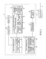
- FIG. 16 is a view showing a configuration of a personal computer 8 according to this modification.
- FIG. 17 is a flowchart showing a technique of detecting the form of the inserting section 11 in the moving state.
- the personal computer 8 includes a communicating section 26 , a physical quantity converting section 28 , a posture detecting section 30 , a linear form detecting section 40 , a drawing section 45 , a display section 47 , and a curve form detecting section 50 .
- An acceleration detecting section 90 is connected to the physical quantity converting section 28 . As shown in FIG. 17 , when detecting a form of the inserting section 11 in the moving state, the acceleration detecting section 90 is configured to acquire acceleration data in the moving state measured by an acceleration sensor A i of each sensor unit S i (a step S 131 ). Further, the acceleration detecting section 90 is configured to divide an acceleration vector measured at the center of each sensor unit Si into an X axis directions component, a Y axis directions component, and a Z axis directions component of a global coordinate system C based on the acceleration data in the moving state. Further, the X axis directions component, the Y axis directions component, and the Z axis directions component of the global coordinate system C of the acceleration vector measured at the center of each sensor unit S i are detected (a step S 132 ).
- an X i axis directions component, a Y i axis directions component, and a Z i axis directions component in a local coordinate system C i of an acceleration vector measured by the acceleration sensor A i of each sensor unit S i are represented as follows:
- an X axis directions component a thi — X , a Y axis directions component a thi — Y , and a Z axis directions component a thi — Z in the global coordinate system C of an acceleration vector other than the gravitational acceleration measured by each sensor unit S i can be obtained.
- a displacement calculating section 92 is connected to the acceleration detecting section 90 .
- the displacement calculating section 92 is configured to calculate a displacement of each sensor unit S i from the previous stationary state based on the acceleration vector other than the gravitational acceleration detected by the acceleration detecting section 90 (a step S 133 ).
- An X axis directions component, a Y axis directions component, and a Z axis directions component in the global coordinate system C of the displacement of each sensor unit S i from the previous stationary state can be obtained by performing double integration with respect to the X axis directions component a thi — X , the Y axis directions component a thi — Y , and the Z axis directions component a thi — Z in the global coordinate system C of the acceleration vector other than the gravitational acceleration measured by each sensor unit S i .
- the displacement calculating section 92 also is configured to calculate an X axis directions component, a Y axis directions component, and a Z axis directions component in the global coordinate system C of a velocity vector of each sensor unit S i .
- the X axis directions component, the Y axis directions component, and the Z axis directions component in the global coordinate system C of the velocity vector of each sensor unit S i can be obtained by performing integration only once with respect to the X axis directions component a thi — X , the Y axis directions component a thi — Y , and the Z axis directions component a thi — Z in the global coordinate system C of the acceleration vector other than the gravitational acceleration measured by each sensor unit S i .
- a movement state detecting section 94 is connected to the displacement calculating section 92 .
- the movement state detecting section 94 is connected to the curve form detecting section 50 .
- a detected curve form 65 of the inserting section 11 in the previous stationary state is detected by the above-described technique (the steps S 101 to S 106 in FIG. 4 ).
- the detected curve form 65 of the inserting section 11 in the previous stationary state is input to the movement state detecting section 94 from the curve form detecting section 50 .
- a calculation result of the X axis directions component, the Y axis directions component, and the Z axis directions component in the global coordinate system C of displacement of each sensor unit S i from the previous stationary state is input to the movement state detecting section 94 from the displacement calculating section 92 .
- the movement state detecting section 94 is configured to detect a movement state of the inserting section 11 from the previous stationary state based on the detected curve form 65 of the inserting section 11 in the previous stationary state and the displacement of each sensor unit S i from the previous stationary state (a step S 134 ). As a result, a form of the inserting section 11 of the endoscope 10 in the moving state is detected.
- the drawing section 45 is connected to the movement state detecting section 94 .
- the detected form of the inserting section 11 in the moving state in the global coordinate system C detected by the movement state detecting section 94 is drawn by the drawing section 45 .
- An operator can confirm the detected form in the moving state drawn by the drawing section 45 in the display section 47 .
- a staying state detecting section 96 is connected to the displacement calculating section 92 .
- a warning section 97 is connected to the staying state detecting section 96 .
- the staying state detecting section 96 is configured to detect a staying state of the inserting section 11 based on X axis directions components, Y axis directions components, and Z axis directions components in the global coordinate system C of the acceleration vector, the velocity vector, and the displacement of each sensor unit S i (a step S 135 ). That is, when observing, e.g., a sigmoid colon by using the endoscope 10 , a state in which the inserting section 11 is staying at an S-top and the like is detected.
- the warning section 98 is configured to carry out warning display (a step S 136 ).
- the warning display is not performed, and the processing advances to a step S 107 (see FIG. 4 ).
- the X axis directions component, the Y axis directions component, and the Z axis directions component in the global coordinate system C of the acceleration vector measured at the center of each sensor unit S i by the acceleration detecting section 90 are detected.
- the displacement calculating section 92 also is configured to calculate the X axis directions components, the Y axis directions components, and the Z axis directions components in the global coordinate system C of the displacement and the velocity vector of each sensor unit S i .
- the movement state detecting section 94 is configured to detect the form of the inserting section 11 in the moving state.
- the staying state detecting section 96 is configured to detect the staying state of the inserting section 11 .
- the warning section 98 is configured to perform the warning display.
- the curve compensating section 51 is configured to first perform the curve interpolation with respect to all the links T j to form the arcs L j in the first embodiment. Further, the arc position compensating section 53 is configured to parallel translate each arc L j in such a manner that the boundaries between the arc L j and the adjacent arcs L j ⁇ 1 and L j+1 become continuous, thereby compensating the position of the arc L j .
- the interpolation sequentially implementing section 71 is configured to sequentially carry out the curve interpolation starting from the link T j on the proximal end side in accordance with each link T j .
- the interpolation uncompleted portion 85 is parallel translated to be continuous with the interpolation completed portion 83 every time the curve interpolation is effected with respect to one link T j , thereby compensating the position of the interpolation uncompleted portion 85 . That is, the detected curve form 65 detected by the curve form detecting section 70 in the first embodiment is equal to the detected curve form 81 detected by the curve form detecting section 70 in the second embodiment.
- the circuit architecture and others are complicated, but the present invention may include a curve form detecting section which is a combination of the first embodiment and the second embodiment.
- this curve form detecting section is configured to first carry out the curve interpolation from the first link to a link T k to form arcs L 1 to L k like the first embodiment and then configured to perform the positional compensation of the arcs L 1 to L k . Furthermore, in regard to a link T k+1 and subsequent links, the positional compensation of the interpolation uncompleted portion 85 is effected every time the curve interpolation of one link T j is carried out like the second embodiment.
- each local coordinate system C i is a coordinate system whose Y i axis directions coincide with the longitudinal directions at the center of the sensor unit S i .
- each local coordinate system C i can suffice as long as an origin is set at the center of the sensor unit S i and axial directions of any one of an X i axis, a Y i axis, and a Z i axis coincide with the longitudinal directions at the center of the sensor unit S i .
- the X i axis is the longitudinal axis
- the following equation is used in place of e yk ⁇ 1 in Expression (16.1) and Expression (16.2):
- e xk ⁇ 1 is a unit vector in X k ⁇ 1 axis directions which are the longitudinal directions at the origin in a local coordinate system C k ⁇ 1
- e zk ⁇ 1 is a unit vector in Z k ⁇ 1 axis directions which are the longitudinal directions at the origin of the local coordinate system C k ⁇ 1 .
- the global coordinate system C is a coordinate system in which an origin is set at the center of the sensor unit S 0 provided on the most proximal end side, a Z axis coincides with the vertical directions, and an X axis and a Y axis are arranged on a horizontal plane.
- any coordinate system can suffice as long as any one of an X axis, a Y axis, and a Z axis is a vertical axis whose axial directions coincide with the vertical directions and two axes other than the vertical axis are horizontal axes arranged on the horizontal plane.
- the posture detecting section 30 can detect a posture of each sensor unit S i based on gravitational acceleration measured by the acceleration sensor A i and geomagnetism measured by the geomagnetic sensor B i .
- the X axis is the vertical axis
- each of an X axis directions component, a Y axis directions component, and a Z axis directions component in the global coordinate system C of a gravitational acceleration vector represented by Expression (2) is as follows:
- a first angle calculating section 34 is configured to calculate the posture angles ⁇ i and ⁇ i about the Y axis and the Z axis which are the horizontal axes based on acceleration data measured by the acceleration sensor A i .
- a second angle calculating section 36 is configured to calculate the posture angle ⁇ i about the X axis which is the vertical axis based on geomagnetic data measured by the geomagnetic sensor B i .
- This configuration is likewise applied when the Y axis is the vertical axis
- the first angle calculating section 34 is configured to calculate the posture angles ⁇ i and ⁇ i about the X axis and the Z axis as the horizontal axes based on the acceleration data measured by the acceleration sensor A i .
- the second angle calculating section 36 is configured to calculate the posture angle ⁇ i on the Y axis which is the vertical axis based on the geomagnetic data measured by the geomagnetic sensor B i .
- the global coordinate system C has the origin set at the center of the sensor unit S 0 provided on the most proximal end side in the foregoing embodiments, it may have the origin at the center of the sensor unit S N provided on the most distal end side.
- a link forming section 41 uses Expression (16.1) and Expression (16.2) to obtain a coordinate P′ j (l xj , l yj , l zj ) of a sensor unit S j ⁇ 1 on a proximal end side (a side far from the origin of the global coordinate system C) of a link T j when a sensor unit S j on a distal end side (a side close to the origin of the global coordinate system C) of the link T j is placed at the origin of the global coordinate system C.
- the link T j is formed by linearly connecting the origin of the global coordinate system C with the coordinate P′ j (l xj , l yj , l zj ).
- the normal line forming section 55 is configured to first form a first interpolation normal line N j that runs through a first end point as a distal end (an end on the side close to the origin of the global coordinate C) of the link T j and is perpendicular to the link T j and a second interpolation normal line N j ⁇ 1 that runs through a second end point as a proximal end (an end on the side far from the origin of the global coordinate C) of the link T j and is perpendicular to a link (an interpolation target adjacent link) T j ⁇ 1 adjacent to the proximal end side (the side far from the origin of the global coordinate C) of the link T j .
- the center deciding section 57 is configured to calculate an intersection O j of the first interpolation normal line N j and the second interpolation normal line N j ⁇ 1 or an intermediate point O j of two points that minimize a distance between the first interpolation normal line N j and the second interpolation normal line N j ⁇ 1 , and configured to decide the intersection O j or the intermediate point O j as the center O j of an arc L j .
- the arc forming section 59 is configured to form an arc L j whose radius R j is equal to a distance between the center O j and the distal end of the link (the interpolation target link) T j and whose arc length starting from the distal end of the link T j is equal to an inter-sensor dimension l.
- the interpolation sequentially implementing section 71 of the curve form detecting section 70 is configured to sequentially perform the curve interpolation from the link T j on the distal end side (the side close to the origin of the global coordinate system C) in accordance with each link T j , thereby forming the arc L j .
Abstract
Description
- This application is a Continuation Application of PCT Application No. PCT/JP2011/059637, filed Apr. 19, 2011 and based upon and claiming the benefit of priority from prior Japanese Patent Application No. 2010-125154, filed May 31, 2010, the entire contents of all of which are incorporated herein by reference.
- 1. Field of the Invention
- The present invention relates to an endoscopic form detection device including an endoscope configured to be inserted into a body cavity and a form detecting method of an inserting section of the endoscope.
- 2. Description of the Related Art
- In recent years, an endoscopic form detection device that can detect a form of an inserting section of an endoscope has been put to practical use. Jpn. Pat. Appln. KOKAI Publication No. 2000-175862 discloses an endoscope insertion form detection device including source coils disposed to an inserting section of an endoscope configured to be inserted into a body cavity. In this endoscope insertion form detection device, positions of the respective source coils are detected by a sense coil provided outside a body. Further, based on the detected positions of the source coils, a form of the inserting section of the endoscope is detected.
- Furthermore, Jpn. Pat. Appln. KOKAI Publication No. 2007-319622 discloses an endoscope device including two sensors disposed to an inserting section of an endoscope. In this endoscope device, a sensor on a proximal end side is determined as a reference, and a position and a posture of a sensor on a distal end side are detected. The sensor on the proximal end side is arranged near a proximal end of a bending section, and the sensor on the distal end side is arranged at a distal-end hard section. A bending angle and a bending direction of the bending section are calculated by detecting the position and the posture of the sensor on the distal end side with respect to the sensor on the proximal end side.
- Further, Jpn. Pat. Appln. KOKAI Publication No. 11-19027 discloses an endoscopic form detection device including gyroscopes disposed to an inserting section of an endoscope. In this endoscopic form detection device, a posture in a predetermined region (a region to which the gyroscope is disposed) of the inserting section of the endoscope is detected by the gyroscope. Furthermore, a form of the inserting section is detected based on the detected posture in the predetermined region.
- According to one aspect of the invention, an endoscopic form detection device includes that an endoscope including an inserting section in which sensor units are arranged in longitudinal directions at intervals of a predetermined inter-sensor dimension; a posture detecting section configured to detect a posture of each of the sensor units based on measurement data in the sensor unit; a linear form detecting section configured to detect a detected linear form of the inserting section of the endoscope on an assumption that a form between the respective sensor units is a linear link whose dimension is equal to the inter-sensor dimension based on the posture of each of the sensor units detected by the posture detecting section; and a curve form detecting section configured to perform curve interpolation with respect to the detected linear form detected by the linear form detecting section on an assumption that a form between the respective sensor units is an arc whose arc length is equal to the inter-sensor dimension, and configured to detect a detected curve form.
- According to one another aspect of the invention, a form detecting method of an inserting section of an endoscope, includes that performing measurement by using sensor units arranged in the inserting section of the endoscope in longitudinal directions at intervals of a predetermined inter-sensor dimension; detecting a posture of each sensor unit by using a posture detecting section based on measurement data in the sensor unit; detecting a detected linear form of the inserting section of the endoscope by using a linear form detecting section on the assumption that a form between the respective sensor units is a linear link whose dimension is equal to the inter-sensor dimension based on the posture of each sensor unit detected by the posture detecting section; and performing curve interpolation with respect to the detected linear form detected by the linear form detecting section and forming a detected curve form by using a curve form detecting section on the assumption that a form between the respective sensor units is an arc whose arc length is equal to the inter-sensor dimension.
- Advantages of the invention will be set forth in the description which follows, and in part will be obvious from the description, or may be learned by practice of the invention. The advantages of the invention may be realized and obtained by means of the instrumentalities and combinations particularly pointed out hereinafter.
- The accompanying drawings, which are incorporated in and constitute a part of the specification, illustrate embodiments of the invention, and together with the general description given above and the detailed description of the embodiments given below, serve to explain the principles of the invention.
-
FIG. 1 is a block diagram showing a configuration of an endoscopic form detection device according to a first embodiment of the present invention; -
FIG. 2 is a schematic view showing a configuration of an inserting section of an endoscope according to the first embodiment; -
FIG. 3 is a block diagram showing a configuration of a personal computer of the endoscopic form detection device according to the first embodiment; -
FIG. 4 is a flowchart showing a method of detecting a form of the inserting section of the endoscope in a stationary state according to the first embodiment; -
FIG. 5 is a schematic view showing a global coordinate system and a corrected coordinate system of the endoscopic form detection device according to the first embodiment in comparison to each other; -
FIG. 6 is a schematic view showing a detected linear form detected by a linear form detecting section of the endoscopic form detection device according to the first embodiment; -
FIG. 7 is a schematic view explaining processing in a link position compensating section of the linear form detecting section according to the first embodiment; -
FIG. 8 is a schematic view showing a detected curve form detected by a curve form detecting section of the endoscopic form detection device according to the first embodiment; -
FIG. 9 is a flowchart showing a method of detecting the detected curve form by the curve form detecting section according to the first embodiment; -
FIG. 10 is a schematic view explaining processing in a curve interpolating section of the curve form detecting section according to the first embodiment; -
FIG. 11 is a schematic view explaining processing in an arc position compensating section of the curve form detecting section according to the first embodiment; -
FIG. 12 is a block diagram showing a configuration of a personal computer of an endoscopic form detection device according to a second embodiment of to the present invention; -
FIG. 13 is a flowchart showing a method of detecting a detected curve form by the curve form detecting section of the endoscopic form detection device according to the second embodiment; -
FIG. 14 is a schematic view explaining processing in an interpolation sequentially implementing section of the curve form detecting section according to the second embodiment; -
FIG. 15 is a schematic view explaining processing in an uninterpolated link position compensating section of the curve form detecting section according to the second embodiment; -
FIG. 16 is a block diagram showing a configuration of a personal computer of an endoscopic form detection device according to a first modification of the present invention; and -
FIG. 17 is a flowchart showing a method of detecting a form of an inserting section of an endoscope in a moving state according to the first modification. - A first embodiment according to the present invention will now be described with reference to
FIG. 1 toFIG. 15 . -
FIG. 1 is a view showing an endoscopicform detection device 1 according to a first embodiment. As shown inFIG. 1 , anendoscope 10 of the endoscopicform detection device 1 includes aninserting section 11 configured to be inserted into a body cavity and anoperating section 12 provided to a proximal end side of theinserting section 11. Theinserting section 11 includes a distal-endhard section 14 provided at a most distal end side; abending section 16 provided to the proximal end side of the distal-endhard section 14, and an elongatedflexible tube section 18 provided to the proximal end side of thebending section 16. - An
imaging element 20 such as a CCD configured to image a subject is provided in the distal-endhard section 14. One end of animaging signal line 21 is connected to theimaging element 20. Theimaging signal line 21 is extended to the outside of theendoscope 10 from theoperating section 12 through theinserting section 11, and the other end of theimaging signal line 21 is connected to avideo processor 3 which is an image processing unit. Furthermore, alight guide 23 configured to guide illumination light applied to a subject is extended to an illumination window (not shown) of the distal-endhard section 14 along longitudinal directions in theinserting section 11. Thelight guide 23 is extended to the outside of theendoscope 10 from theoperating section 12 and connected to alight source unit 4. - Moreover, one end of each of four bending operation wires (not shown) as bending operation transmission members is connected to a distal end portion of the
bending section 16 in theinserting section 11. The other end of each bending operation wire is connected to a bending operation knob (not shown), which is a bending operating section provided to theoperating section 12, through theflexible tube section 18. The bending operation wires move in the longitudinal directions by operations using the bending operation knob. The bendingsection 16 is configured to bend in up-down directions and left-right directions of theendoscope 10 by the movement of the bending operation wires. - A plurality of (N+1 in this embodiment) sensor units S0 to SN are provided in the inserting
section 2. The respective sensor units Si (i=0, 1, 2, . . . , N) are arranged to be apart from each other in the longitudinal directions at fixed intervals (=50 mm). That is, respective sensor units Si are arranged to be apart from each other in the longitudinal directions at intervals of a predetermined inter-sensor dimension l. Here, for example, the sensor unit S0 provided on a most proximal end side is arranged in a proximal end portion of theflexible tube section 18, and the sensor unit SN provided on the most distal end side is arranged in the distal end portion of thebending section 16. Each sensor unit Si includes an accelerator sensor Ai configured to measure acceleration, and a geomagnetic sensor Bi configured to measure earth magnetism. -
FIG. 2 is a view showing the insertingsection 11 of theendoscope 10. As shown inFIG. 2 , each sensor unit Si has a local coordinate system Ci (indicated by a dotted line inFIG. 2 ) having an origin at the center of the sensor unit Si, and also having an Xi axis, a Yi axis, and a Zi axis. Here, the Xi axis directions coincide with the left-right directions of theendoscope 10 at the center of the sensor unit Si, and a right direction of theendoscope 10 as seen from the proximal end side is determined to be positive. The Yi axis directions coincide with the longitudinal directions at the center of the sensor unit Si, and the distal end side direction is determined to be positive. The Zi axis directions coincide with the up-down directions of theendoscope 10 at the center of the sensor unit Si, and an up direction of theendoscope 10 is determined to be positive. The acceleration sensor Ai is configured to measure an Xi axis directions component, a Yi axis directions component, and a Zi axis directions component of acceleration at the origin of the local coordinate system Ci. - Furthermore, in the endoscopic
form detection device 1, a global coordinate system C (indicated by a solid line inFIG. 2 ) having an X axis, a Y axis, and a Z axis is defined with the center of the sensor unit S0 provided on the most proximal end side being determined as an origin. Here, the global coordinate system C is a rectangular Cartesian coordinate system for a right-hand system with the center of the sensor unit S0 provided on the most proximal end side determined as an origin. The X-axis directions coincide with predetermined directions (directions parallel to arrows D1 and D2 inFIG. 2 in this embodiment) perpendicular to vertical directions in which gravity functions, and a direction of the arrow D1 inFIG. 2 is determined to be positive. The Y axis directions coincide with directions (directions parallel to arrows E1 and E2 inFIG. 2 in this embodiment) perpendicular to the vertical directions and the X axis directions, and a direction of the arrow E1 inFIG. 2 is determined to be positive. The Z axis directions coincide with the vertical directions, and an up direction (direction extending from a back side to a front side of a paper sheet) of the vertical directions is determined to be positive. It is to be noted that a positive direction of the X axis directions of the global coordinate system is determined as a magnetic north direction for convenience of explanation. - Each local coordinate system Ci is a coordinate system obtained by rotating the global coordinate system C αi about the X axis, βi about the Y axis, and γi about the Z axis and parallel translating the origin from the center of the sensor unit S0 provided on the most proximal end side to the center of the sensor unit Si. Here, αi is referred to as a pitch angle, βi is referred to as a roll angle, γi is referred to as a yaw angle, and three angles, i.e., the pitch angle αi, the roll angle βi, and the yaw angle γi will be generically referred to as posture angles. A clockwise direction of each posture angle αi, βi, or γi seen from a negative direction of each of the X axis, the Y axis, and the Z axis is determined to be positive. A posture of the sensor unit Si can be detected by calculating values of the posture angles αi, βi, and γi.
- As shown in
FIG. 1 , aserial bus 5 such as 12C is connected to the acceleration sensor Ai and the geomagnetic sensor Bi of each sensor unit Si. Theserial bus 5 is extended to the outside of theendoscope 10 from the operatingsection 12 through the inside of the insertingsection 11, and its proximal end is connected to aserial converter 6. Theserial converter 6 is configured to convert a serial signal of measurement data input from each sensor unit Si through theserial bus 5 into a USB signal. One end of aUSB cable 7 is connected to theserial converter 6. The other end of theUSB cable 7 is connected to apersonal computer 8. The USB signal of the measurement data in each sensor unit Si is configured to be input to thepersonal computer 8 from theserial converter 6. -
FIG. 3 is a view showing a configuration of thepersonal computer 8. As shown inFIG. 3 , thepersonal computer 8 includes a communicatingsection 26 connected to theserial converter 6 through theUSB cable 7. The communicatingsection 26 is configured to receive the measurement data in each sensor unit Si. A physicalquantity converting section 28 is connected to the communicatingsection 26. The physicalquantity converting section 28 is configured to convert the measurement data in each sensor unit Si received by a communicatingsection 26 into a physical quantity by using an offset, a gain, and others. - A
posture detecting section 30 is connected to the physicalquantity converting section 28. Theposture detecting section 30 is configured to detect a posture of each sensor unit Si based on the measurement data in each sensor unit Si. Theposture detecting section 30 includes a postureangle calculating section 32 configured to calculate the three posture angles αi, βi, and γi as rotational angles in the local coordinate system Ci of each sensor unit Si about the X axis, the Y axis, and the Z axis from the global coordinate system C based on measurement data obtained by the acceleration sensor Ai and the geomagnetic sensor Bi of each sensor unit Si. The postureangle calculating section 32 includes a firstangle calculating section 34 configured to calculate a pitch angle αi as a rotational angle in the local coordinate system Ci of each sensor unit Si about the X axis from the global coordinate system C and a roll angle βi as a rotational angle in the local coordinate system Ci of each sensor unit Si about the Y axis from the global coordinate system C based on measurement data in the acceleration sensor Ai and the geomagnetic sensor Bi of each sensor unit Si. Moreover, the postureangle calculating section 32 also includes a secondangle calculating section 36 configured to calculate a yaw angle γi as a rotational angle in the local coordinate system Ci of each sensor unit Si about the Z axis from the global coordinate system C based on the geomagnetic data in the geomagnetic sensor Bi of each sensor unit Si. - A method of detecting a posture of each sensor unit Si by the
posture detecting section 30 will now be described.FIG. 4 is a flowchart showing a form detecting method of the insertingsection 11 in a stationary state in which the insertingsection 11 of theendoscope 10 is stopped. As shown inFIG. 4 , when detecting a form of the insertingsection 11, each sensor unit Si first performs measurement (a step S101), and theposture detecting section 30 acquires measurement data in each sensor unit Si. Additionally, the postureangle calculating section 32 calculates the three posture angles αi, βi, and γi in the local coordinate system Ci of each sensor unit Si. - When calculating the posture angles αi, βi, and γi, the first
angle calculating section 34 first calculates the pitch angle αi and the roll angle βi in the local coordinate system Ci of each sensor unit Si (a step S102) based on the measurement data in the acceleration sensor Ai of each sensor unit Si. Here, the posture angles αi, βi, and γi are determined as a (Z, X, Y) type that rotates in the order of the yaw angle γi, the pitch angle αi, and the roll angle βi. Therefore, a rotation matrix from the global coordinate system C to the local coordinate system Ci is as follows: -
- In the stationary state in which the inserting
section 11 is stopped, gravitational acceleration alone functions downward in the vertical directions. That is, in both the global coordinate system C and the local coordinate system Ci, the gravitational acceleration alone functions downward in the vertical directions. Therefore, at this time, an X axis directions component, a Y axis directions component, and a Z axis directions component of an acceleration vector in the global coordinate system C are as follows: -
{dot over (a)} th=[0 0−g] T (2) - Further, it is assumed that an Xi axis directions component, a Yi axis directions component, and a Zi axis directions component of an acceleration vector in the local coordinate system Ci measured by the acceleration sensor Ai are as follows:
-
{dot over (a)} obsi =[a Bi— X a Bi— Y a Bi— Z]T (3) - Here, the local coordinate system Ci is a coordinate system obtained by rotating the global coordinate system C in the order of the yaw angle γi, the pitch angle αi, and the roll angle βi. Therefore, based on Expression (1) to Expression (3), acceleration components observed in the local coordinate system Ci are as follows:
-
- Here, when a square of Expression (4.1) is added to a square of Expression (4.2), the following expression can be obtained:
-
a Bi— X 2 +a Bi— Z 2 =g 2 cos2αi(sin2βi+cos2βi) (5) - Further, the following expression is derived:
-
g cos αi=√{square root over (aBi— X 2 +a Bi— Z 2)} (6)= - Furthermore, when Expression (4.2) is divided by Expression (6), the following expression can be obtained:
-
- As a result, the pitch angle αi in the local coordinate system Ci can be obtained. Moreover, when Expression (4.1) is divided by Expression (4.3), the following expression can be obtained:
-
- The roll angle βi in the local coordinate system Ci can be derived. As described above, based on measurement data in each acceleration sensor Ai, the pitch angle αi and the roll angle βi in the local coordinate system Ci can be calculated.
- Additionally, the second
angle calculating section 36 calculates the yaw angle γi in the local coordinate system Ci of each sensor unit Si based on measurement data obtained by the geomagnetic sensor Bi of each sensor unit Si (a step S103). Here, a corrected coordinate system C′i obtained by correcting the rotation from the global coordinate system C about the X axis and the rotation from the global coordinate system C about the Y axis in each local coordinate system Ci is defined by using the pitch angle αi and the roll angle βi calculated at the step S102.FIG. 5 is a view showing the global coordinate system C (indicated by a solid line inFIG. 5 ) and the corrected coordinate system C′i (indicated by a dotted line inFIG. 5 ). It is to be noted that the global coordinate system C and the corrected coordinate system C′i actually have origins provided at different positions, andFIG. 5 shows a state in which the origins are provided at the same position in order to compare both the coordinate systems. As shown inFIG. 5 , the corrected coordinate system C′i obtained by correcting the rotation about the X axis and the rotation about the Y axis is a coordinate system obtained by rotating the global coordinate system C by the yaw angle γi about the Z axis and has an X′i axis, a Y′i axis, and a Z′i axis. X′i directions and Y′i axis directions coincide with directions rotated by the yaw angle γi about the Z axis from the X axis directions and the Y axis directions in the global coordinate system C, respectively. Z′i axis directions coincide with the vertical directions, i.e., the Z axis directions in the global coordinate system C. Here, since the positive direction of the X axis directions in the global coordinate system C coincides with the magnetic north direction, a positive direction of the X′i directions is a direction rotated by the yaw angle γi about the Z axis from the magnetic north direction. - It is assumed that an Xi axis directions component, a Yi axis directions component, and a Zi axis directions component of a geomagnetic vector in the local coordinate system Ci measured by the geomagnetic sensor Bi are as follows:
-
{dot over (m)}obsi=[M Xi M Yi M Zi]T (9) - The corrected coordinate system C′i is a coordinate system obtained by correcting the rotation from the global coordinate system C about the X axis and the rotation from the global coordinate system C about the Y axis in the local coordinate system Ci. Therefore, based on Rxi and Ryi in Expression (1) and Expression (9), an X′i axis directions component, a Y′i axis directions component, and a Z′i axis directions component in the corrected coordinate system C′i of a geomagnetic vector measured by the geomagnetic sensor Bi are as follows:
-
- Based on Expression (10.1) and Expression (10.2), the following expressions can be obtained:
-
M Xi ′=M Xi cos βi +M Zi sin βi (11.1) -
M Yi ′=M Yi cos αi+sin αi(M Xi sin βi −M zi cos βi) (11.2) - A geomagnetic component on a horizontal plane (an X′i-Y′i plane in the corrected coordinate system C′i) perpendicular to the vertical directions directs the magnetic north direction. Therefore, based on Expression (11.2) and Expression (11.2), an angle θi from the X′i axis to the magnetic north direction can be obtained by using the X′i axis component and the Y′i axis component of the geomagnetic vector in the corrected coordinate system C′i. That is, the following expression can be obtained:
-
θi=tan−1(M Yi ′/M Xi′) (12) - In regard to the angle θi, a clockwise direction when seeing the Z′i axis (the Z axis) from a negative direction is determined to be positive. Here, the corrected coordinate system C′i is a coordinate system obtained by rotating the global coordinate system C the yaw angle γi about the Z axis. Therefore, the angle θi obtained based on Expression (12) is the yaw angle γi in the local coordinate system Ci when the global coordinate system C is determined as a reference.
- It is to be noted that, when one of the X axis directions in the global coordinate system C does not coincide with the magnetic north direction, the yaw angle γi can be likewise obtained with reference to the magnetic north. An X axis directions component, a Y axis directions component, and a Z axis directions component of the geomagnetic vector in the global coordinate system C are determined as follows:
-
{dot over (m)}th =[E X E Y E Z]T (13) - The X axis directions component, the Y axis directions component, and the Z axis directions component of the geomagnetic vector in the global coordinate system C can be obtained by using a geomagnetic sensor which is of the same type as the geomagnetic sensor Bi to conduct the measurement in a state in which the X axis directions, the Y axis directions, and the Z axis directions in the global coordinate system C coincide with axis directions. Further, based on Expression (13), an angle θ from the X axis to the magnetic north direction is obtained by using the X axis component and the Y axis component of the geomagnetic vector in the global coordinate system C. That is, the following expression can be acquired:
-
θ=tan−1(E Y /E X) (14) - Here, in regard to the angle θ, the clockwise direction when the Z axis is seen from the negative direction is determined to be positive. The corrected coordinate system C′i is a coordinate system obtained by rotating the global coordinate system C by the yaw angle γi about the Z axis. Therefore, based on Expression (12) and Expression (14), the following representation can be achieved:
-
γi=θ−θi (15) - As a result, when the global coordinate system C is determined as a reference the yaw angle γi of the local coordinate system Ci can be obtained.
- As described above, based on the measurement data in each geomagnetic sensor Bi, the yaw angle γi of each local coordinate system Ci is calculated. Based on the calculated values of the posture angles αi, βi, and γi, the
posture detecting section 30 is configured to detect a posture of each sensor unit Si. - As shown in
FIG. 3 , a linearform detecting section 40 is connected to theposture detecting section 30.FIG. 6 is a view showing a detectedlinear form 71 of the insertingsection 11 of theendoscope 10 detected by the linearform detecting section 40 from the positive direction of the Z axis in the global coordinate C. As shown inFIG. 6 , the linearform detecting section 40 is configured to detect the detectedlinear form 71 of the insertingsection 11 on the assumption that a form between the respective sensor units Si is a linear link Tj (j=, 1, 2, . . . N) whose dimension is equal to theinter-sensor dimension 1 based on the posture of each sensor unit Si detected by theposture detecting section 30. Here, the kth link Tk from the proximal end side is a link between the kth sensor unit Sk−1 from the proximal end side and the (K+1)th sensor unit Sk from the proximal end side. The linearform detecting section 40 includes alink forming section 41 configured to form each link Tj, and a linkposition compensating section 42 configured to parallel translate each link Tj formed by thelink forming section 41 to compensate a position of the link Tj. The linkposition compensating section 42 is configured to parallel translate each link Tj in such a manner that link boundaries between the link Tj and adjacent links Tj−1 and Tj+1 become continuous. - A
drawing section 45 is connected to the linearform detecting section 40. Adisplay section 47 is connected to thedrawing section 45. The detectedlinear form 71 of the insertingsection 11 in the global coordinate system C detected by the linearform detecting section 40 is configured to be drawn by thedrawing section 45. An operator can confirm the detectedlinear form 71 drawn by thedrawing section 45 in thedisplay section 47. - A method of detecting the detected
linear form 71 of the insertingsection 11 in the linearform detecting section 40 will now be described. As shown inFIG. 4 , when detecting the detectedlinear form 71 of the insertingsection 11, thelink forming section 41 first forms each link Tj having the linear form based on the values of the posture angles αi, βi, and γi calculated at the steps S102 and S103 (a step S104). Here, description will be given as to formation of a kth link Tk from the proximal end side between a kth sensor unit Sk−1 from the proximal end side and a (k+1)th sensor unit Sk from the proximal end side. - As represented by Expression (7), Expression (8), and Expression (12) (or Expression (15)), posture angles αk−1, βk−1, and γk−1 in a local coordinate system Ck−1 (i.e., the link) are calculated at the steps S102 and S103. Each of the posture angles αk−1, βk−1, and γk−1 and the inter-sensor dimension l which is between each of the sensor units Si can be used to obtain a coordinate P′k(lxk, lyk, lzk) of the sensor unit Sk when the sensor unit Sk−1 is placed at the origin of the global coordinate system C. Here, the coordinate P′k is represented as follows:
-
- In Expression (16.1) and Expression (16.2), eyk−1 is a unit vector in Yk−1 axis directions which are the longitudinal directions at the origin of the local coordinate system Ck−1. When the unit vector eyk−1 is multiplied by a rotation matrix calculated by Expression (1), an X axis directions component, a Y axis directions component, and a Z axis directions component of the unit vector eyk−1 in the global coordinate system C can be calculated, respectively. That is, lxk, lyk, and lzk are components obtained by dividing a vector having a magnitude l in the Yk−1 axis directions in the local coordinate system Ck−1 to the X axis directions, the Y axis directions, and the Z axis directions in the global coordinate system C, respectively. The link Tk is formed by linearly connecting the origin of the global coordinate system C with the coordinate P′k(lxk, lyk, lzk) calculated by Expression (16.1) and Expression (16.2).
- It is to be noted that each link Tj other than the link Tk is likewise formed by the
link forming section 41. That is, Expression (16.1) and Expression (16.2) are used to obtain a coordinate P′j(lxj, lyj, lzj) of the sensor unit Sj on the distal end side (the side far from the origin of the global coordinate system C) of the link Tj when the sensor unit Sj−1 on the proximal end side (the side close to the origin of the global coordinate system C) of the link Tj is placed at the origin of the global coordinate system C. Further, the link Tj is formed by linearly connecting the origin of the global coordinate system C to the coordinate P′j(lxj, lyj, lzj). That is, thelink forming section 41 is configured to form the link Tj on the assumption that the link Tj is extended in the longitudinal directions at the center of the sensor unit Sj−1 on the proximal end side from the center of the sensor unit Sj−1 on the proximal end side (the side close to the origin of the global coordinate system C) to the center of the sensor unit Sj on the distal end side (the side far from the origin of the global coordinate system C). - Furthermore, it is preferable for the inter-sensor dimension l to be approximately 50 mm. When the inter-sensor dimension l is increased, the number of the sensor units Si is reduced, thereby decreasing a cost. Moreover, when the inter-sensor dimension l is smaller than approximately 50 mm, an error when detecting a form of the inserting
section 11 can be reduced even if the interval between the respective sensor units Si is assumed to be the linear link Tj whose dimension is equal to the inter-sensor dimension l. - Additionally, the link
position compensating section 42 is configured to correct a position of the link Tj by parallel translating each link Tj formed by thelink forming section 41 in such a manner that link boundaries between the link Tj and adjacent links Tj−1 and Tj+1 become continuous (a step S105).FIG. 7 is a view explaining processing in the linkposition compensating section 42. Here, description will be given as to positional compensation of the kth link Tk from the proximal end side between the kth sensor unit Sk−1 from the proximal end side and the (k+1)th sensor unit Sk from the proximal end side. - As shown in
FIG. 7 , in a state before the linkposition compensating section 42 performs positional compensation of the link Tk, the positional compensation is completed from the first link to the link Tk−1 adjacent to the proximal end side of the link Tk, and a link positional compensation completedportion 73 is formed. When performing the positional compensation of the link Tk, the linkposition compensating section 42 parallel translates the link Tk a distance from the origin to the distal end of the link positional compensation completedportion 73. That is, the link Tk is parallel translated from a position indicated by a dotted line inFIG. 7 to a position indicated by a solid line inFIG. 7 . As a result, a link boundary between the link Tk−1 and the link Tk becomes continuous, and the position of the link Tk is thereby compensated. - It is to be noted that a position of each link Tj other than the link Tk is likewise compensated. That is, when performing the positional compensation of the link Tj, the link
position compensating section 42 is configured to parallel translate the link Tj a distance from the origin to the distal end (the end on the side far from the origin of the global coordinate system C) of the link positional compensation completedportion 73. As a result, a link boundary between the link Tj and a link Tj−1 adjacent to the proximal end side (the side close to the origin of the global coordinate system C) of the link Tj becomes continuous, and a position of the link Tj is thereby compensated. However, a position of a link Tl is not compensated since a proximal end of the link Tl is the origin of the global coordinate system C. - As shown in
FIG. 3 , a linearform detecting section 40 is connected to a curveform detecting section 50.FIG. 8 is a view showing a detectedcurve form 65 of the insertingsection 11 of theendoscope 10 detected by the curveform detecting section 50 from a positive direction of the Z axis of the global coordinate system C. As shown inFIG. 8 , the curveform detecting section 50 is configured to perform curve interpolation with respect to the detectedlinear form 61 on the assumption that a form between respective sensor units Si is an arc Lj (j=1, 2, . . . N) whose arc length is equal to the inter-sensor dimension l. The detectedcurve form 65 is formed by performing the curve interpolation. Here, a kth arc Lk from the proximal end side is an arc between a kth sensor unit Sk−1 from the proximal end side and a (k+1)th sensor unit Sk from the proximal end side. - The curve
form detecting section 50 includes acurve interpolating section 51 configured to perform the curve interpolation in accordance with each link Tj to form the arc Lj, aninterpolation controlling section 52 configured to control thecurve interpolating section 51 to perform the curve interpolation with respect to all the links Tj, and an arcposition compensating section 53 configured to parallel translate each arc Lj formed by thecurve interpolating section 51 to compensate a position of the arc Lj. The arcposition compensating section 53 is configured to translate each arc Lj in such a manner that arc boundaries between the arc Lj and adjacent arcs Lj−1 and Lj+1 become continuous. - As shown in
FIG. 3 , thecurve interpolating section 51 includes a normalline forming section 55, acenter deciding section 57, and anarc forming section 59. Details of the normalline forming section 55, thecenter deciding section 57, and thearc forming section 59 will be described later. - The
drawing section 45 is connected to the curveform detecting section 50. The detectedcurve form 65 of the insertingsection 11 in the global coordinate system C formed by the curveform detecting section 50 is drawn by thedrawing section 45. An operator can confirm the detectedcurve form 65 drawn by thedrawing section 45 in thedisplay section 47. - Here, description will be given as to a method of performing the curve interpolation with respect to the detected
linear form 61 detected by the linearform detecting section 40 to detect the detectedcurve form 65. As shown inFIG. 4 , the curveform detecting section 50 is configured to carry out the curve interpolation of the detectedlinear form 61 on the assumption that a form between the respective sensor units Si is the arc Lj whose arc length is equal to the inter-sensor dimension l, and configured to estimate the detected curve form 65 (a step S106). As described above, if the inter-sensor dimension l is smaller than approximately 50 mm, the error in the detection of the form of the insertingsection 11 is small even though the portion between the respective sensor units Si is the linear link Tj whose dimension is equal to the inter-sensor dimension l. However, a form of the insertingsection 11 of theendoscope 10 when inserted into a body cavity is a curve form. Therefore, it is important to perform the curve interpolation of the detectedlinear form 61. Here, although there are differences among products, the insertingsection 11 of theendoscope 10 has appropriate elasticity. Therefore, a curvature of the curved form of the insertingsection 11 varies only slightly. Therefore, when the curve interpolation is performed on the assumption that the form between the sensor units Si is the arc Lj having a radius Rj (curvature/Rj), it is possible to form the detectedcurve form 65 having a small error from an actual curve form of the insertingsection 11. - When performing the curve interpolation of the detected
linear form 61 to detect the detectedcurve form 65, thecurve interpolating section 51 is configured to carry out the curve interpolation in accordance with each link Tj to form the arc Lj. Here, a method of performing the curve interpolation of the link Tj by thecurve interpolating section 51 will be explained. Here, description will be given as to the curve interpolation of a kth link Tk from the proximal end side between a kth sensor unit Sk−1 from the proximal end side and a (k+1)th sensor unit Sk from the proximal end side. -
FIG. 9 is a flowchart showing a method of using the curveform detecting section 50 to detect the detectedcurve form 65 from the detectedlinear form 61.FIG. 10 is a view explaining processing in thecurve interpolating section 51. As shown inFIG. 10 , in a state before the curve interpolation of the link (an interpolation target link) Tk as an interpolation target is carried out by thecurve interpolating section 51, the sensor unit Sk is placed at a point Q′k. As shown inFIG. 9 andFIG. 10 , when performing the curve interpolation of the link (the interpolation target link) Tk by thecurve interpolating section 51, the normalline forming section 55 is configured to first form a first interpolation normal line Nk−1 that runs through a proximal end (a first end point) of the link Tk and is perpendicular to the link Tk and a second interpolation normal line Nk that runs through a distal end (a second end point) of the link Tk and is perpendicular to a link (an interpolation target adjacent link) Tk+1 adjacent to the distal end side of the link Tk (a step S111). That is, the first interpolation normal line Nk−1 can be obtained under conditions that it is perpendicular to a directional vector of the link Tk and that it runs through the sensor unit (the first endpoint) Sk−1. Likewise, the second interpolation normal line Nk can be obtained under conditions that it is perpendicular to a directional vector of the link Tk+1 and that it runs through the sensor unit (a second end point) Sk. - Furthermore, the
center deciding section 57 is configured to calculate an intersection Ok of the first interpolation normal line Nk−1 and the second interpolation normal line Nk and to decide the intersection Ok as the center of an arc Lk (a step S112). If the first interpolation normal line Nk−1 and the second interpolation normal line Nk do not cross each other, an intermediate point Ok of two points that minimize a distance between the first interpolation normal line Nk−1 and the second interpolation normal line Nk is calculated. When calculating the intermediate point Ok, an equation of a straight line (not shown) perpendicular to both the first interpolation normal line Nk−1 and the second interpolation normal line Nk is first obtained. Further, an intersection of this straight line and the first interpolation normal line Nk−1 and an intersection of this straight line and the second interpolation normal line Nk are obtained, and an intermediate point of the two intersections is the intermediate point Ok. Moreover, the intermediate point Ok is determined as the center Ok of the arc Lk (a step S112). - Additionally, the
arc forming section 59 is configured to form the arc Lk (a step S113). The arc Lk has a radius Rk equal to a distance between the center Ok decided by thecenter deciding section 57 and the proximal end (the first end point) of the link (the interpolation target link) Tk. That is, the arc Lk hascurvature 1/Rk. Further, the ark Lk is the arc Lk whose arc length starting from the proximal end (the first end point) of the link Tk is equal to the inter-sensor dimension l. A distal end Qk of the arc Lk is a position of the sensor unit Sk after the curve interpolation. That is, the position of the sensor unit Sk moves from the point Q′k to the point Qk by the curve interpolation of the link Tk. As described above, the curve interpolation of the link Tk is performed. - It is to be noted that the curve interpolation is likewise carried out with respect to each link Tj other than the link Tk by the
curve interpolating section 51. That is, when performing the curve interpolation of the link (an interpolation target link) Tj, the normalline forming section 55 is configured to form a first interpolation normal line Nj−1 that runs through a first end point which is a proximal end (an end on a side close to the origin of the global coordinate C) of the link Tj and is perpendicular to the link Tj and a second interpolation normal line Nj that runs through a second end point which is a distal end (an end on a side far from the origin of the global coordinate C) of the link Tj and is perpendicular to a link (an interpolation target adjacent link) Tj+1 adjacent to the distal end side (the side far from the origin of the global coordinate C) of the link Tj (the step S111). Furthermore, thecenter deciding section 57 is configured to calculate an intersection Oj of the first interpolation normal line Nj−1 and the second interpolation normal line Nj or an intermediate point Oj of two points that minimize a distance between the first interpolation normal line Nj−1 and the second interpolation normal line Nj, and configured to decide the intersection Oj or the intermediate point Oj as the center Oj of an arc Lj (the step S112). Moreover, thearc forming section 59 is configured to form the arc Lj whose radium Rj is equal to a distance between the center Oj and the proximal end of the link (the interpolation target link) Tj and whose arc length starting from the proximal end of the link Tj is equal to the inter-sensor dimension l (the step S113). - Additionally, as shown in
FIG. 9 , theinterpolation controlling section 52 is configured to confirm whether the curve interpolation has been completed with regard to all the links Tj (a step S114). When the curve interpolation has been completed with respect to all the links Tj, the processing advances to the next step (the step S114-Yes). When the curve interpolation has not been completed in regard to all the links Tj, the processing returns to the step S111 (the step S114-No), and thecurve interpolating section 51 is configured to perform the curve interpolation with respect to the links Tj which have not been subjected to the curve interpolation. That is, thecurve interpolating section 51 is configured to be controlled to carry out the steps S111 to S113 until the curve interpolation is completed with respect to all the links Tj (N links in this embodiment). - When the curve interpolation has been effected with respect to all the links Tj by the
curve interpolating section 51, each arc Lj formed by thecurve interpolating section 51 is parallel translated by the arcposition compensating section 53 in such a manner that arc boundaries between the arc Lj and adjacent arcs Lj−1 and Lj+1 become continuous, thereby compensating a position of the arc Lj (a step S115).FIG. 11 is a view explaining processing in the arcposition compensating section 53. Here, description will be given as to positional compensation of the kth arc Lk from the proximal end side between the kth sensor unit Sk−1 from the proximal end side and the sensor unit Sk from the proximal end side. - As shown in
FIG. 11 , in a state before the positional compensation of the arc Lk is carried out by the arcposition compensating section 53, the positional compensation from the first arc to an arc Lk−1 adjacent to the proximal end side of the arc Lk has been completed, whereby an arc positional compensation completedportion 67 is formed. When carrying out the positional compensation of the arc Lk, the arcposition compensating section 53 is configured to parallel translate the arc Lk a distance from the proximal end of the arc Lk before the positional compensation to the distal end of the arc position compensation completedportion 67. That is, the arc Lk is parallel translated from a position indicated by a dotted line inFIG. 11 to a position indicated by a solid line inFIG. 11 . As a result, an arc boundary between the arc Lk−1 and the arc Lk becomes continuous, and the position of the arc Lk is compensated. - It is to be noted that a position of each arc Lj other than the arc Lk is also compensated by the arc
position compensating section 53. That is, when performing the positional compensation of the arc Lj, the arcposition compensating section 53 is configured to parallel translate the arc Lj a distance from a proximal end of the arc Lj before the positional compensation to the distal end (the end on the side far from the origin of the global coordinate system C) of the arc position compensation completedportion 67. As a result, an arc boundary between the arc Lj and an arc Lj−1 adjacent to the proximal end side (the side close to the origin of the global coordinate system C) of the arc Lj becomes continuous, and the position of the arc Lj is compensated. However, in regard to an arc L1, since a proximal end of the arc L1 is the origin of the global coordinate system C, the positional compensation is not performed. - As shown in
FIG. 4 , when the curve interpolation of the detectedlinear form 61 by the curveform detecting section 50 is completed and the detectedcurve form 65 is formed, whether inspection by the endoscopicform detection device 1 has been completed is confirmed (a step S107). When the inspection has not been completed (the step S107-No), the processing returns to the step S101 to detect a form of the insertingsection 11 of theendoscope 10 in the next stationary state. When the inspection has been completed (the step S107-Yes), the form detection of the insertingsection 11 of theendoscope 10 is finished. - Therefore, the endoscopic
form detection device 1 and the form detecting method of the insertingsection 11 of theendoscope 10 using the endoscopicform detection device 1 exercise the following effect. That is, in the endoscopicform detection device 1, aposture detecting section 30 is configured to detect a posture of each sensor unit Si from measurement data of the sensor unit Si, and the linearform detecting section 40 is configured to detect the detectedlinear form 61 of the insertingsection 11 of theendoscope 10 from the posture of each sensor unit Si. Furthermore, the curveform detecting section 50 is configured to carry out the curve interpolation of the detectedlinear form 61 to detect the detectedlinear form 65. As described above, since the detectedlinear form 65 of the insertingsection 11 is detected from the measurement data of each sensor unit Si arranged in the insertingsection 11 configured to be inserted in a body cavity at the time of observation, a sense coil and others do not have to be provided outside a body. Therefore, miniaturization and simplification of the endoscopicform detection device 1 can be realized. - Additionally, in the endoscopic
form detection device 1, the curveform detecting section 50 is configured to perform the curve interpolation of the detectedlinear form 61 on the assumption that a form between the respective sensor units Si is the arc Lj whose arc length is equal to the inter-sensor dimension l, and configured to detect the detectedcurve form 65. In fact, although there are differences among products, the insertingsection 11 of theendoscope 10 has appropriate elasticity. Therefore, a curvature of the curved form of the insertingsection 11 varies only slightly. Therefore, when the curve interpolation is performed on the assumption that a form between the sensor units Si is the arc L1 having a radius Rj (curvature 1/Rj), it is possible to detect the detectedcurve form 65 having a small error from an actual curved form of the insertingsection 11. As a result, the detectedcurve form 65 of the insertingsection 11 can be highly accurately detected. - Further, in the endoscopic
form detection device 1, an acceleration sensor Ai is configured to measure gravitational acceleration and a geomagnetic sensor Bi is configured to measure geomagnetism in the stationary state in which the insertingsection 11 is not moving. Furthermore, theposture detecting section 30 is configured to detect a posture of each sensor unit Si from the measured gravitational acceleration and geomagnetism. In the stationary state, each of the gravitational acceleration and the geomagnetism constantly has a fixed intensity in a fixed direction. Since a posture of each sensor unit Si is detected from the gravitational acceleration and the geomagnetism, the posture of the sensor unit Si can be highly accurately detected even in the stationary state. As a result, the detectedcurve form 65 of the insertingsection 11 can be highly accurately detected. - A second embodiment according to the present invention will now be described with reference to
FIG. 12 toFIG. 15 . It is to be noted that like reference numerals denote the same parts or parts having the same functions as those in the first embodiment, thereby omitting description thereof. -
FIG. 12 is a view showing a configuration of apersonal computer 8 according to this embodiment. As shown inFIG. 12 , apersonal computer 8 includes a communicatingsection 26, a physicalquantity converting section 28, aposture detecting section 30, a linearform detecting section 40, adrawing section 45, and adisplay section 47 like the first embodiment. A curveform detecting section 70 is connected to the linearform detecting section 40 and thedrawing section 45. - Like the curve
form detecting section 50 according to the first embodiment, the curveform detecting section 70 is configured to perform curve interpolation with respect to a detectedlinear form 61 on the assumption that a form between respective sensor units Si is an arc Lj (j=1, 2, . . . N) whose arc length is equal to an inter-sensor dimension l, and configured to detect a detectedcurve form 81. However, a technique of detecting the detectedcurve form 81 is different from that of the curveform detecting section 50. - The curve
form detecting section 70 includes an interpolation sequentially implementingsection 71 as a curve interpolating section configured to sequentially perform curve interpolation in accordance with each link Tj starting from a link Tj on a proximal end side (a side close to an origin of a global coordinate system C) to form an arc Lj, and aninterpolation controlling section 72 configured to control the interpolation sequentially implementingsection 71 to carry out the curve interpolation with respect to all the links Tj. Further, the curveform detecting section 70 includes an uninterpolated linkposition compensating section 73 configured to parallel translate an interpolationuncompleted portion 85 constituted of a link that is not subjected to the curve interpolation (an uninterpolated link) Tj to compensate a position every time the curve interpolation of one link Tj is carried out by the interpolation sequentially implementingsection 71. The interpolationuncompleted portion 85 is parallel translated by the uninterpolated linkposition compensating section 73 in such a manner that a boundary between the interpolationuncompleted portion 85 and an interpolation completedportion 83 constituted of an arc Lj formed by the curve interpolation becomes continuous. - As shown in
FIG. 12 , the interpolation sequentially implementingsection 71 includes a normalline forming section 75, acenter deciding section 77, and anarc forming section 79. Details of the normalline forming section 75, thecenter deciding section 77, and thearc forming section 79 will be described later. - Here, description will now be given as to a method of using the curve
form detecting section 70 to perform the curve interpolation of the detectedlinear form 61 detected by the linearform detecting section 40 and to thereby detect the detectedcurve form 81. Like the curveform detecting section 50 according to the first embodiment, the curveform detecting section 70 is configured to carry out the curve interpolation of the detectedlinear form 61 on the assumption that a form between the respective sensor units Si is the arc Lj whose arc length is equal to the inter-sensor dimension l (a step S106 inFIG. 4 ). As a result, as described in the first embodiment, the detectedcurve form 81 having a small error from an actual curve form of the insertingsection 11 is formed. - When performing the curve interpolation of the detected
linear form 61, the interpolation sequentially implementingsection 71 is configured to sequentially carry out the curve interpolation in accordance with each link Tj starting from the link Tj on the proximal end side (the side close to the origin of the global coordinate system C) to form the arc Lj. Here, a method of using the interpolation sequentially implementingsection 71 to perform the curve interpolation of the link Tj will now be described. Here, description will be given as to the curve interpolation of a kth link Tk from the proximal end side between a kth sensor unit Sk−1 from the proximal end side and a (k+1)th sensor unit Sk from the proximal end side. -
FIG. 13 is a flowchart showing a method of detecting the detectedcurve form 81 from the detectedlinear form 61 by the curveform detecting section 70.FIG. 14 is a view explaining processing in the interpolation sequentially implementingsection 71. As shown inFIG. 14 , in a state before the curve interpolation of the link Tk is carried out by the interpolation sequentially implementingsection 71, the curve interpolation from a first link to a link Tk−1 has been completed, and an interpolation completedportion 83 is formed. The interpolation completedportion 83 is constituted of arcs L1 to Lk−1. Further, an interpolationuncompleted portion 85 constituted of links (interpolation uncompleted links) Tk to TN which have not been subjected to the interpolation is formed. At this time, a boundary between the interpolation completedportion 83 and the interpolationuncompleted portion 85 is continuous, and the sensor unit Sk is placed at a point U′k. - In this state, the interpolation sequentially implementing
section 71 is configured to carry out the curve interpolation of the link (an interpolation target link) Tk placed on the most proximal end side in the interpolationuncompleted portion 85. As shown inFIG. 13 andFIG. 14 , when performing the curve interpolation of the link Tk, the normalline forming section 75 is configured to first form a first interpolation normal line Nk−1 that runs through a proximal end (a first end point) of the link Tk and is perpendicular to the link Tk and a second interpolation normal line Nk that runs through a distal end (a second end point) of the link Tk and is perpendicular to a link (an interpolation target adjacent link) Tk+1 adjacent to the distal end side of the link Tk (a step S121). - Furthermore, the
center deciding section 77 is configured to calculate an intersection Ok of the first interpolation normal line Nk−1 and the second interpolation normal line Nk and configured to decide the intersection Ok as the center of an arc Lk (a step S122). If the first interpolation normal line Nk−1 and the second interpolation normal line Nk do not cross each other, an intermediate point Ok of two points that minimize a distance between the first interpolation normal line Nk−1 and the second interpolation normal line Nk is calculated. The intermediate point Ok is calculated by the same technique as that in the first embodiment. Moreover, the intermediate point Ok is determined as the center Ok of the arc Lk (a step S122). - Additionally, the
arc forming section 79 is configured to form the arc Lk (a step S123). The arc Lk has a radius Rk equal to a distance between the center Ok decided by thecenter deciding section 77 and the proximal end of the link (the interpolation target link) Tk. That is, the arc Lk hascurvature 1/Rk. Further, the arc Lk is the arc Lk whose arc length starting from the proximal end of the link Tk is equal to the inter-sensor dimension l. A distal end Uk of the arc Lk is a position of the sensor unit Sk after the curve interpolation. That is, the position of the sensor unit Sk moves from the point U′k to the point Uk by the curve interpolation of the link Tk. When the position of the sensor unit Sk moves, the boundary between the interpolation completedportion 83 and the interpolationuncompleted portion 85, which was continuous in the state before the curve interpolation of the link Tk was carried out by the interpolation sequentially implementingsection 71, becomes discontinuous. That is, the arc Lk and the link Tk+1 become discontinuous. - It is to be noted that the curve interpolation is likewise carried out with respect to each link Tj other than the link Tk by the interpolation sequentially implementing
section 71. That is, when performing the curve interpolation of the link (an interpolation target link) Tj, the normalline forming section 75 is configured to form a first interpolation normal line Nj−1 that runs through a first end point which is a proximal end (an end on a side close to the origin of the global coordinate C) of the link Tj and is perpendicular to the link Tj and a second interpolation normal line Nj that runs through a second end point which is a distal end (an end on a side far from the origin of the global coordinate C) of the link Tj and is perpendicular to a link (an interpolation target adjacent link) Tj+1 adjacent to the distal end side (the side far from the origin of the global coordinate C) of the link Tj (the step S121). Furthermore, thecenter deciding section 77 is configured to calculate an intersection Oj of the first interpolation normal line Nj−1 and the second interpolation normal line Nj or an intermediate point Oj of two points that minimize a distance between the first interpolation normal line Nj−1 and the second interpolation normal line Nj and configured to decide the intersection Oj or the intermediate point Oj as the center Oj of an arc Lj (the step S122). Moreover, thearc forming section 79 is configured to form the arc Lj whose radius Rj is equal to a distance between the center Oj and the proximal end of the link (the interpolation target link) Tj and whose arc length starting from the proximal end of the link Tj is equal to the inter-sensor dimension l (the step S123). -
FIG. 15 is a view explaining processing in the unimplemented linkposition compensating section 73. As shown inFIG. 15 , a state after the curve interpolation of the link Tk was carried out by the interpolation sequentially implementingsection 71 to form the arc Lk, the interpolation completedportion 83 which has been completely subjected to the curve interpolation and the interpolationuncompleted portion 85 which has not been subjected to the curve interpolation are formed. The interpolation completedportion 83 is constituted of the arcs L1 to Lk, and the interpolationuncompleted portion 85 is constituted of the links Tk+1 to TN. At this time, since the position of the sensor unit Sk is moved from the point U′k to the point Uk by the curve interpolation of the link Tk as described above, the boundary between the interpolation completedportion 83 and the interpolationuncompleted portion 85 is discontinuous. In this state, the uninterpolated linkposition compensating section 73 is configured to parallel translate the interpolationuncompleted portion 85 in such a manner that the boundary between the interpolationuncompleted portion 85 and the interpolation completedportion 83 becomes continuous to compensate the position of the interpolation uncompleted portion 85 (a step S124). That is, the interpolationuncompleted portion 85 is parallel translated from the position indicated by the dotted line inFIG. 15 to the position indicated by the solid line inFIG. 15 . - It is to be noted that, in regard to each link Tj other than the link Tk, a position of the interpolation
uncompleted portion 85 is likewise compensated by the uninterpolated linkposition compensating section 73. That is, after the curve interpolation of the link Tj is performed by the interpolation sequentially implementingsection 71, the boundary between the interpolation completedportion 83 and the interpolationuncompleted portion 85 is discontinuous. In this state, the uninterpolated linkposition compensating section 73 is configured to parallel translate the interpolationuncompleted portion 85 to be continuous with the interpolation completedportion 83, thereby compensating the position of the interpolation uncompleted portion 85 (the step S124). The uninterpolated linkposition compensating section 73 is configured to compensate the position of the interpolationuncompleted portion 85 every time the curve interpolation of one link Tj is carried out by the interpolation sequentially implementingsection 71. - Furthermore, as shown in
FIG. 13 , theinterpolation controlling section 72 is configured to confirm whether the curve interpolation has been completed with respect to all the links T1 (a step S125). When the curve interpolation has been completed with respect to all the links Tj, the detectedcurve form 81 of the insertingsection 11 is formed, and the processing advances to the next step (the step S125-Yes). When the curve interpolation has not been completed with respect to all the links Tj, the processing returns to the step S121 (the step S125-No), and the interpolation sequentially implementingsection 71 performs the curve interpolation of the link (the interpolation target link) Tj placed on the most proximal end side (the side close to the origin of the global coordinate system C) in the interpolationuncompleted portion 85. That is, the interpolation sequentially implementingsection 71 is configured to be controlled in such a manner that the steps S121 to S123 are carried out until the curve interpolation is completed with respect to all the links Tj. Moreover, when the interpolation sequentially implementingsection 71 performs the curve interpolation of the next link Tj (the steps S121 to S123), the uninterpolated linkposition compensating section 73 is configured to compensate the position of the interpolation uncompleted portion 85 (the step S124). - Therefore, the endoscopic
form detection device 1 and the form detecting method of the insertingsection 11 of theendoscope 10 using the endoscopicform detection device 1 exercise the following effect. That is, in the endoscopicform detection device 1, theposture detecting section 30 is configured to detect a posture of each sensor unit Si from measurement data of each sensor unit Si, and the linearform detecting section 40 is configured to detect the detectedlinear form 61 of the insertingsection 11 of theendoscope 10 from the posture of each sensor unit Si. Furthermore, the curveform detecting section 70 is configured to carry out the curve interpolation of the detectedlinear form 61 to detect the detectedcurve form 81. As described above, since the detectedcurve form 81 of the insertingsection 11 is detected from the measurement data of each sensor unit Si arranged in the insertingsection 11 configured to be inserted in a body cavity at the time of observation, a sense coil and others do not have to be provided outside a body. Therefore, miniaturization and simplification of the endoscopicform detection device 1 can be realized. - Additionally, in the endoscopic
form detection device 1, the curveform detecting section 70 is configured to perform the curve interpolation of the detectedlinear form 61 on the assumption that a form between the respective sensor units Si is the arc Lj whose arc length is equal to the inter-sensor dimension l, and configured to detect the detectedcurve form 81. In fact, although there are differences among products, the insertingsection 11 of theendoscope 10 has appropriate elasticity. Therefore, curvature of the curved form of the insertingsection 11 varies only slightly. Therefore, when the curve interpolation is performed on the assumption that a form between the sensor units Si is the arc Lj having a radius Rj (curvature 1/Rj), it is possible to detect the detectedcurve form 81 having a small error from an actual curved form of the insertingsection 11. As a result, the detectedcurve form 81 of the insertingsection 11 can be highly accurately detected. - Further, in the endoscopic
form detection device 1, an acceleration sensor Ai is configured to measure gravitational acceleration and a geomagnetic sensor Bi is configured to measure geomagnetism in the stationary state in which the insertingsection 11 is not moving. Furthermore, theposture detecting section 30 is configured to detect a posture of each sensor unit Si from the measured gravitational acceleration and geomagnetism. In the stationary state, each of the gravitational acceleration and the geomagnetism constantly has a fixed intensity in a fixed direction. Since a posture of each sensor unit Si is detected from the gravitational acceleration and the geomagnetism, the posture of the sensor unit Si can be highly accurately detected even in the stationary state. As a result, the detectedcurve form 81 of the insertingsection 11 can be highly accurately detected. - (First Modification)
- A first modification of the foregoing embodiment will now be described with reference to
FIG. 16 andFIG. 17 . It is to be noted that like reference numerals denote the same parts and parts having the same functions as those in the first embodiment and the second embodiment, thereby omitting description thereof. - In this modification, a form of an inserting
section 11 can be detected in a moving state in which the insertingsection 11 of anendoscope 10 is being parallel translated. The detection of the form of the insertingsection 11 in the moving state is carried out between the step S106 and the step S107 inFIG. 4 .FIG. 16 is a view showing a configuration of apersonal computer 8 according to this modification.FIG. 17 is a flowchart showing a technique of detecting the form of the insertingsection 11 in the moving state. - As shown in
FIG. 16 , like the first embodiment, thepersonal computer 8 includes a communicatingsection 26, a physicalquantity converting section 28, aposture detecting section 30, a linearform detecting section 40, adrawing section 45, adisplay section 47, and a curveform detecting section 50. - An
acceleration detecting section 90 is connected to the physicalquantity converting section 28. As shown inFIG. 17 , when detecting a form of the insertingsection 11 in the moving state, theacceleration detecting section 90 is configured to acquire acceleration data in the moving state measured by an acceleration sensor Ai of each sensor unit Si (a step S131). Further, theacceleration detecting section 90 is configured to divide an acceleration vector measured at the center of each sensor unit Si into an X axis directions component, a Y axis directions component, and a Z axis directions component of a global coordinate system C based on the acceleration data in the moving state. Further, the X axis directions component, the Y axis directions component, and the Z axis directions component of the global coordinate system C of the acceleration vector measured at the center of each sensor unit Si are detected (a step S132). - Here, description will now be given as to a technique of detecting the X axis directions component, the Y axis directions component, and the Z axis directions component in the global coordinate system C of the acceleration vector measured at the center of each sensor unit Si by the
acceleration detecting section 90. In the moving state, since components produced due to movement of the insertingsection 11 are added to gravitational acceleration generated in the vertical directions in the stationary state, the X axis directions component, the Y axis directions component, and the Z axis directions component in the global coordinate system C of the acceleration vector measured at the center of each sensor unit Si are represented as follows: -
{dot over (a)} thi =[a thi— X a thi— Y −g+a thi— Z]T (17) - Moreover, an Xi axis directions component, a Yi axis directions component, and a Zi axis directions component in a local coordinate system Ci of an acceleration vector measured by the acceleration sensor Ai of each sensor unit Si are represented as follows:
-
{dot over (a)} obsi ′=[a Bi— X ′a Bi— Y a Bi— Z′]T (18) - Additionally, in this modification, since a situation where the inserting
section 11 of theendoscope 10 is being parallel translated is considered, it is assumed that the sensor units arranged in proximity to each other have the same acceleration vector in the global coordinate system C. In theactual endoscope 10, since the inter-sensor dimension l between the respective sensor units Si is very small, such an assumption is possible. When the assumption is set in this manner, the following relationship is achieved between, e.g., an acceleration vector measured by a sensor unit S1 and acceleration vector measured by a sensor unit S2: -
{dot over (a)} th1 ={dot over (a)} th2 (19.1) -
∥{dot over (a)} obs1 ′∥=∥{dot over (a)} obs2′∥ (19.2) - Additionally, based on Expression (19.1) and Expression (19.2), the following relationship can be achieved:
-
- Here, in the sensor unit S1, based on a relationship between the global coordinate system C and the local coordinate system C1, the following expression can be attained by using a rotation matrix in Expression (1):
-
- Likewise, in the sensor unit S2, based on a relationship between the global coordinate system C and a local coordinate system O2, the following expression can be achieved by using the rotation matrix in Expression (1):
-
- When Expression (21) and (22) are solved by utilizing the relationship represented by Expression (20.1), an X axis directions component ath1
— X (ath2— X), a Y axis directions component ath1— Y (ath2— Y), and a Z axis directions component ath1— Z (ath2— Z) in the global coordinate system C of the acceleration vector other than the gravitational acceleration measured in the sensor unit S1 or S2 can be obtained. When the rotation matrix in Expression (1) is used, a relationship between the respective axis directions components in the global coordinate system C of a geomagnetic vector measured by a geomagnetic sensor Bi represented by Expression (13) and respective axis directions components in the local coordinate system Ci of a geomagnetic vector represented by Expression (9) is as follows: -
- When solving Expressions (20.1), (21), and (22) including the relational expression of the geomagnetism obtained by i=1 (or 2) assigned in Expression (23), a total of 12 unknowns, i.e., six posture angels and six accelerations are present with respect to 12 equations. As a result, it is possible to mathematically solve the X axis directions component ath1
— X(ath2— X), the Y axis directions component ath1— Y(ath2— Y), and the Z axis directions component ath1— Z(ath2— Z) in the global coordinate system C of the acceleration vector other than the gravitational acceleration measured by each of the sensor unit S1 and S2. In regard to any other sensor unit Si, likewise, an X axis directions component athi— X, a Y axis directions component athi— Y, and a Z axis directions component athi— Z in the global coordinate system C of an acceleration vector other than the gravitational acceleration measured by each sensor unit Si can be obtained. - A
displacement calculating section 92 is connected to theacceleration detecting section 90. Thedisplacement calculating section 92 is configured to calculate a displacement of each sensor unit Si from the previous stationary state based on the acceleration vector other than the gravitational acceleration detected by the acceleration detecting section 90 (a step S133). An X axis directions component, a Y axis directions component, and a Z axis directions component in the global coordinate system C of the displacement of each sensor unit Si from the previous stationary state can be obtained by performing double integration with respect to the X axis directions component athi— X, the Y axis directions component athi— Y, and the Z axis directions component athi— Z in the global coordinate system C of the acceleration vector other than the gravitational acceleration measured by each sensor unit Si. Additionally, thedisplacement calculating section 92 also is configured to calculate an X axis directions component, a Y axis directions component, and a Z axis directions component in the global coordinate system C of a velocity vector of each sensor unit Si. The X axis directions component, the Y axis directions component, and the Z axis directions component in the global coordinate system C of the velocity vector of each sensor unit Si can be obtained by performing integration only once with respect to the X axis directions component athi— X, the Y axis directions component athi— Y, and the Z axis directions component athi— Z in the global coordinate system C of the acceleration vector other than the gravitational acceleration measured by each sensor unit Si. - A movement
state detecting section 94 is connected to thedisplacement calculating section 92. The movementstate detecting section 94 is connected to the curveform detecting section 50. As shown inFIG. 17 , when detecting a form of the insertingsection 11 in the moving state, a detectedcurve form 65 of the insertingsection 11 in the previous stationary state is detected by the above-described technique (the steps S101 to S106 inFIG. 4 ). The detectedcurve form 65 of the insertingsection 11 in the previous stationary state is input to the movementstate detecting section 94 from the curveform detecting section 50. Furthermore, a calculation result of the X axis directions component, the Y axis directions component, and the Z axis directions component in the global coordinate system C of displacement of each sensor unit Si from the previous stationary state is input to the movementstate detecting section 94 from thedisplacement calculating section 92. The movementstate detecting section 94 is configured to detect a movement state of the insertingsection 11 from the previous stationary state based on the detectedcurve form 65 of the insertingsection 11 in the previous stationary state and the displacement of each sensor unit Si from the previous stationary state (a step S134). As a result, a form of the insertingsection 11 of theendoscope 10 in the moving state is detected. - The
drawing section 45 is connected to the movementstate detecting section 94. The detected form of the insertingsection 11 in the moving state in the global coordinate system C detected by the movementstate detecting section 94 is drawn by thedrawing section 45. An operator can confirm the detected form in the moving state drawn by thedrawing section 45 in thedisplay section 47. - Additionally, a staying
state detecting section 96 is connected to thedisplacement calculating section 92. A warning section 97 is connected to the stayingstate detecting section 96. The stayingstate detecting section 96 is configured to detect a staying state of the insertingsection 11 based on X axis directions components, Y axis directions components, and Z axis directions components in the global coordinate system C of the acceleration vector, the velocity vector, and the displacement of each sensor unit Si (a step S135). That is, when observing, e.g., a sigmoid colon by using theendoscope 10, a state in which the insertingsection 11 is staying at an S-top and the like is detected. As a result, an operator can confirm whether an operation in theoperating section 12 has been transmitted to the insertingsection 11. When the insertingsection 11 is staying (the step S135-Yes), thewarning section 98 is configured to carry out warning display (a step S136). When the insertingsection 11 is not staying (the step S135-No), the warning display is not performed, and the processing advances to a step S107 (seeFIG. 4 ). - As described above, in the endoscopic
form detection device 1 according to this modification, the X axis directions component, the Y axis directions component, and the Z axis directions component in the global coordinate system C of the acceleration vector measured at the center of each sensor unit Si by theacceleration detecting section 90 are detected. Further, thedisplacement calculating section 92 also is configured to calculate the X axis directions components, the Y axis directions components, and the Z axis directions components in the global coordinate system C of the displacement and the velocity vector of each sensor unit Si. Based on the calculated acceleration vector, velocity vector, displacement, and the detectedform 65 in the previous stationary state, the movementstate detecting section 94 is configured to detect the form of the insertingsection 11 in the moving state. Furthermore, based on the calculated acceleration vector, velocity vector, and displacement, the stayingstate detecting section 96 is configured to detect the staying state of the insertingsection 11. Moreover, when the staying state is detected, thewarning section 98 is configured to perform the warning display. With such a configuration, an operator can confirm whether an operation in theoperating section 12 has been transmitted to the insertingsection 11. As a result, when operating theendoscope 10, the operator can make a more appropriate judgment. - (Other Modifications)
- It is to be noted that the
curve compensating section 51 is configured to first perform the curve interpolation with respect to all the links Tj to form the arcs Lj in the first embodiment. Further, the arcposition compensating section 53 is configured to parallel translate each arc Lj in such a manner that the boundaries between the arc Lj and the adjacent arcs Lj−1 and Lj+1 become continuous, thereby compensating the position of the arc Lj. On the other hand, in the second embodiment, the interpolation sequentially implementingsection 71 is configured to sequentially carry out the curve interpolation starting from the link Tj on the proximal end side in accordance with each link Tj. Furthermore, the interpolationuncompleted portion 85 is parallel translated to be continuous with the interpolation completedportion 83 every time the curve interpolation is effected with respect to one link Tj, thereby compensating the position of the interpolationuncompleted portion 85. That is, the detectedcurve form 65 detected by the curveform detecting section 70 in the first embodiment is equal to the detectedcurve form 81 detected by the curveform detecting section 70 in the second embodiment. Based on the above configuration, the circuit architecture and others are complicated, but the present invention may include a curve form detecting section which is a combination of the first embodiment and the second embodiment. For example, this curve form detecting section is configured to first carry out the curve interpolation from the first link to a link Tk to form arcs L1 to Lk like the first embodiment and then configured to perform the positional compensation of the arcs L1 to Lk. Furthermore, in regard to a link Tk+1 and subsequent links, the positional compensation of the interpolationuncompleted portion 85 is effected every time the curve interpolation of one link Tj is carried out like the second embodiment. - Moreover, in the foregoing embodiments, each local coordinate system Ci is a coordinate system whose Yi axis directions coincide with the longitudinal directions at the center of the sensor unit Si. However, in the present invention, each local coordinate system Ci can suffice as long as an origin is set at the center of the sensor unit Si and axial directions of any one of an Xi axis, a Yi axis, and a Zi axis coincide with the longitudinal directions at the center of the sensor unit Si. However, when the Xi axis is the longitudinal axis, the following equation is used in place of eyk−1 in Expression (16.1) and Expression (16.2):
-
e xk−1=[1 0 0]T (24) - Likewise, when the Zi axis is the longitudinal axis, the following equation is used in place of eyk−1 in Expression (16.1) and Expression (16.2):
-
e zk−1=[0 0 1]T (25) - Here, exk−1 is a unit vector in Xk−1 axis directions which are the longitudinal directions at the origin in a local coordinate system Ck−1, and ezk−1 is a unit vector in Zk−1 axis directions which are the longitudinal directions at the origin of the local coordinate system Ck−1.
- Furthermore, in the foregoing embodiments, the global coordinate system C is a coordinate system in which an origin is set at the center of the sensor unit S0 provided on the most proximal end side, a Z axis coincides with the vertical directions, and an X axis and a Y axis are arranged on a horizontal plane. However, in the present invention, any coordinate system can suffice as long as any one of an X axis, a Y axis, and a Z axis is a vertical axis whose axial directions coincide with the vertical directions and two axes other than the vertical axis are horizontal axes arranged on the horizontal plane. As a result, the
posture detecting section 30 can detect a posture of each sensor unit Si based on gravitational acceleration measured by the acceleration sensor Ai and geomagnetism measured by the geomagnetic sensor Bi. However, when the X axis is the vertical axis, each of an X axis directions component, a Y axis directions component, and a Z axis directions component in the global coordinate system C of a gravitational acceleration vector represented by Expression (2) is as follows: -
{dot over (a)} th =[−g0 0]T (26) - In this case, although the posture angles αi, βi, and γi are the (Z, X, Y) type by which rotation is effected in the order of the yaw angle γi, the pitch angle αi, and the roll angle βi in the first embodiment, the rotation order of the posture angles αi, βi, and γi is changed and a rotation matrix different from that in Expression (1) is used. As a result, a first
angle calculating section 34 is configured to calculate the posture angles βi and γi about the Y axis and the Z axis which are the horizontal axes based on acceleration data measured by the acceleration sensor Ai. Further, a secondangle calculating section 36 is configured to calculate the posture angle αi about the X axis which is the vertical axis based on geomagnetic data measured by the geomagnetic sensor Bi. This configuration is likewise applied when the Y axis is the vertical axis, and the firstangle calculating section 34 is configured to calculate the posture angles αi and γi about the X axis and the Z axis as the horizontal axes based on the acceleration data measured by the acceleration sensor Ai. Furthermore, the secondangle calculating section 36 is configured to calculate the posture angle βi on the Y axis which is the vertical axis based on the geomagnetic data measured by the geomagnetic sensor Bi. - Moreover, although the global coordinate system C has the origin set at the center of the sensor unit S0 provided on the most proximal end side in the foregoing embodiments, it may have the origin at the center of the sensor unit SN provided on the most distal end side. In this case, a
link forming section 41 uses Expression (16.1) and Expression (16.2) to obtain a coordinate P′j (lxj, lyj, lzj) of a sensor unit Sj−1 on a proximal end side (a side far from the origin of the global coordinate system C) of a link Tj when a sensor unit Sj on a distal end side (a side close to the origin of the global coordinate system C) of the link Tj is placed at the origin of the global coordinate system C. Additionally, the link Tj is formed by linearly connecting the origin of the global coordinate system C with the coordinate P′j (lxj, lyj, lzj). - Further, in this case, when performing the curve interpolation with respect to the link (an interpolation target link) Tj by the curve interpolating section 51 of the curve form detecting section 50, the normal line forming section 55 is configured to first form a first interpolation normal line Nj that runs through a first end point as a distal end (an end on the side close to the origin of the global coordinate C) of the link Tj and is perpendicular to the link Tj and a second interpolation normal line Nj−1 that runs through a second end point as a proximal end (an end on the side far from the origin of the global coordinate C) of the link Tj and is perpendicular to a link (an interpolation target adjacent link) Tj−1 adjacent to the proximal end side (the side far from the origin of the global coordinate C) of the link Tj. Furthermore, the center deciding section 57 is configured to calculate an intersection Oj of the first interpolation normal line Nj and the second interpolation normal line Nj−1 or an intermediate point Oj of two points that minimize a distance between the first interpolation normal line Nj and the second interpolation normal line Nj−1, and configured to decide the intersection Oj or the intermediate point Oj as the center Oj of an arc Lj. Moreover, the arc forming section 59 is configured to form an arc Lj whose radius Rj is equal to a distance between the center Oj and the distal end of the link (the interpolation target link) Tj and whose arc length starting from the distal end of the link Tj is equal to an inter-sensor dimension l.
- Additionally, in this case, the interpolation sequentially implementing
section 71 of the curveform detecting section 70 is configured to sequentially perform the curve interpolation from the link Tj on the distal end side (the side close to the origin of the global coordinate system C) in accordance with each link Tj, thereby forming the arc Lj. - Additional advantages and modifications will readily occur to those skilled in the art. Therefore, the invention in its broader aspects is not limited to the specific details and representative embodiments shown and described herein. Accordingly, various modifications may be made without departing from the spirit or scope of the general inventive concept as defined by the appended claims and their equivalents.
Claims (16)
Applications Claiming Priority (3)
| Application Number | Priority Date | Filing Date | Title |
|---|---|---|---|
| JP2010-125154 | 2010-05-31 | ||
| JP2010125154 | 2010-05-31 | ||
| PCT/JP2011/059637 WO2011152141A1 (en) | 2010-05-31 | 2011-04-19 | Endoscope shape detection device and method for detecting shape of inserted part of endoscope |
Related Parent Applications (1)
| Application Number | Title | Priority Date | Filing Date |
|---|---|---|---|
| PCT/JP2011/059637 Continuation WO2011152141A1 (en) | 2010-05-31 | 2011-04-19 | Endoscope shape detection device and method for detecting shape of inserted part of endoscope |
Publications (2)
| Publication Number | Publication Date |
|---|---|
| US20120053418A1 true US20120053418A1 (en) | 2012-03-01 |
| US8419619B2 US8419619B2 (en) | 2013-04-16 |
Family
ID=45066525
Family Applications (1)
| Application Number | Title | Priority Date | Filing Date |
|---|---|---|---|
| US13/229,182 Active 2031-07-15 US8419619B2 (en) | 2010-05-31 | 2011-09-09 | Endoscopic form detection device and form detecting method of insertion section of endoscope |
Country Status (5)
| Country | Link |
|---|---|
| US (1) | US8419619B2 (en) |
| EP (1) | EP2446806A4 (en) |
| JP (1) | JP4897121B2 (en) |
| CN (1) | CN102481089B (en) |
| WO (1) | WO2011152141A1 (en) |
Families Citing this family (5)
| Publication number | Priority date | Publication date | Assignee | Title |
|---|---|---|---|---|
| CN102621584B (en) * | 2011-12-14 | 2015-07-22 | 吉林大学 | Aeromagnetic vector data processing method |
| JP6128796B2 (en) * | 2012-10-25 | 2017-05-17 | オリンパス株式会社 | INSERTION SYSTEM, INSERTION SUPPORT DEVICE, OPERATION METHOD AND PROGRAM FOR INSERTION SUPPORT DEVICE |
| JP2015181643A (en) * | 2014-03-24 | 2015-10-22 | オリンパス株式会社 | Curved shape estimation system, tubular insert system, and method for estimating curved shape of curved member |
| CN104142119B (en) * | 2014-08-20 | 2017-06-09 | 广州市易轩生物科技有限公司 | Flexible pipe 3D shape sensing device |
| CN111012289A (en) * | 2019-12-24 | 2020-04-17 | 西安申兆光电科技有限公司 | Curved shape detection device, detection method and endoscope system |
Citations (10)
| Publication number | Priority date | Publication date | Assignee | Title |
|---|---|---|---|---|
| US6059718A (en) * | 1993-10-18 | 2000-05-09 | Olympus Optical Co., Ltd. | Endoscope form detecting apparatus in which coil is fixedly mounted by insulating member so that form is not deformed within endoscope |
| US20040116775A1 (en) * | 1999-08-05 | 2004-06-17 | Olympus Optical Co., Ltd. | Apparatus and method using it for detecting and displaying form of insertion part of endoscope inserted into body cavity |
| US20050284221A1 (en) * | 2004-06-25 | 2005-12-29 | Lee Danisch | Shape-acceleration measurement device and method |
| US20060173289A1 (en) * | 2003-08-22 | 2006-08-03 | Chieko Aizawa | Device for detecting shape of endoscope |
| US20070106116A1 (en) * | 2005-11-09 | 2007-05-10 | Pentax Corporation | Endoscope-shape monitoring system |
| US20070106114A1 (en) * | 2005-11-09 | 2007-05-10 | Pentax Corporation | Endoscope-shape monitoring system |
| US20070112247A1 (en) * | 2005-11-16 | 2007-05-17 | Yasuo Hirata | Endoscope |
| US7691056B2 (en) * | 2003-12-19 | 2010-04-06 | Olympus Corporation | Endoscope apparatus |
| US20100191056A1 (en) * | 2007-10-02 | 2010-07-29 | Olympus Medical Systems Corp. | Endoscope shape analysis apparatus |
| US20100204545A1 (en) * | 2007-11-29 | 2010-08-12 | Olympus Medical Systems Corp. | Endoscope system |
Family Cites Families (11)
| Publication number | Priority date | Publication date | Assignee | Title |
|---|---|---|---|---|
| JP3910688B2 (en) * | 1997-07-01 | 2007-04-25 | オリンパス株式会社 | Endoscope shape detection device and endoscope shape detection method |
| JP3290153B2 (en) * | 1998-12-17 | 2002-06-10 | オリンパス光学工業株式会社 | Endoscope insertion shape detection device |
| JP4142189B2 (en) * | 1998-12-28 | 2008-08-27 | オリンパス株式会社 | Endoscope shape detection system |
| US6612992B1 (en) * | 2000-03-02 | 2003-09-02 | Acuson Corp | Medical diagnostic ultrasound catheter and method for position determination |
| US10555775B2 (en) * | 2005-05-16 | 2020-02-11 | Intuitive Surgical Operations, Inc. | Methods and system for performing 3-D tool tracking by fusion of sensor and/or camera derived data during minimally invasive robotic surgery |
| US9661991B2 (en) * | 2005-08-24 | 2017-05-30 | Koninklijke Philips N.V. | System, method and devices for navigated flexible endoscopy |
| JP4708963B2 (en) * | 2005-11-09 | 2011-06-22 | Hoya株式会社 | Endoscope insertion part shape grasping system |
| JP2007319622A (en) | 2006-06-05 | 2007-12-13 | Olympus Corp | Endoscope system |
| CN101099657A (en) * | 2007-07-13 | 2008-01-09 | 上海大学 | Thin long flexible rod spatial shape detecting device and method |
| JP5011057B2 (en) * | 2007-10-11 | 2012-08-29 | オリンパスメディカルシステムズ株式会社 | Endoscope shape analyzer |
| JP5259340B2 (en) * | 2008-10-28 | 2013-08-07 | オリンパスメディカルシステムズ株式会社 | Medical equipment |
-
2011
- 2011-04-19 JP JP2011535736A patent/JP4897121B2/en not_active Expired - Fee Related
- 2011-04-19 EP EP11789550.8A patent/EP2446806A4/en not_active Withdrawn
- 2011-04-19 CN CN201180003546.7A patent/CN102481089B/en active Active
- 2011-04-19 WO PCT/JP2011/059637 patent/WO2011152141A1/en active Application Filing
- 2011-09-09 US US13/229,182 patent/US8419619B2/en active Active
Patent Citations (11)
| Publication number | Priority date | Publication date | Assignee | Title |
|---|---|---|---|---|
| US6059718A (en) * | 1993-10-18 | 2000-05-09 | Olympus Optical Co., Ltd. | Endoscope form detecting apparatus in which coil is fixedly mounted by insulating member so that form is not deformed within endoscope |
| US20040116775A1 (en) * | 1999-08-05 | 2004-06-17 | Olympus Optical Co., Ltd. | Apparatus and method using it for detecting and displaying form of insertion part of endoscope inserted into body cavity |
| US20060173289A1 (en) * | 2003-08-22 | 2006-08-03 | Chieko Aizawa | Device for detecting shape of endoscope |
| US7691056B2 (en) * | 2003-12-19 | 2010-04-06 | Olympus Corporation | Endoscope apparatus |
| US20050284221A1 (en) * | 2004-06-25 | 2005-12-29 | Lee Danisch | Shape-acceleration measurement device and method |
| US7296363B2 (en) * | 2004-06-25 | 2007-11-20 | N.B. Inc. | Shape-acceleration measurement device and method |
| US20070106116A1 (en) * | 2005-11-09 | 2007-05-10 | Pentax Corporation | Endoscope-shape monitoring system |
| US20070106114A1 (en) * | 2005-11-09 | 2007-05-10 | Pentax Corporation | Endoscope-shape monitoring system |
| US20070112247A1 (en) * | 2005-11-16 | 2007-05-17 | Yasuo Hirata | Endoscope |
| US20100191056A1 (en) * | 2007-10-02 | 2010-07-29 | Olympus Medical Systems Corp. | Endoscope shape analysis apparatus |
| US20100204545A1 (en) * | 2007-11-29 | 2010-08-12 | Olympus Medical Systems Corp. | Endoscope system |
Also Published As
| Publication number | Publication date |
|---|---|
| US8419619B2 (en) | 2013-04-16 |
| EP2446806A1 (en) | 2012-05-02 |
| CN102481089A (en) | 2012-05-30 |
| JPWO2011152141A1 (en) | 2013-07-25 |
| EP2446806A4 (en) | 2017-06-21 |
| WO2011152141A1 (en) | 2011-12-08 |
| CN102481089B (en) | 2014-09-17 |
| JP4897121B2 (en) | 2012-03-14 |
Similar Documents
| Publication | Publication Date | Title |
|---|---|---|
| US8585585B2 (en) | Endoscopic form detection device and form detecting method of insertion section of endoscope | |
| US8698886B2 (en) | Apparatus for estimating shape of insertion portion | |
| US20110060185A1 (en) | Medical device system and calibration method for medical instrument | |
| EP2460457B1 (en) | Endoscope shape detection device and method for detecting shape of insertion portion of endoscope | |
| US8419619B2 (en) | Endoscopic form detection device and form detecting method of insertion section of endoscope | |
| CN108882837A (en) | Utilize the automatic calibration of the endoscope of bracing wire | |
| US20070106115A1 (en) | Endoscope-shape monitoring system | |
| EP2581027B1 (en) | Probe shape detection apparatus and probe shape detection method | |
| JP4967858B2 (en) | Calibration method and apparatus between camera and robot | |
| US8403829B2 (en) | Endoscopic form detection device and form detecting method of insertion section of endoscope | |
| JP5870656B2 (en) | Trajectory calculation device and trajectory calculation method | |
| JP2019072259A (en) | Endoscope image processing program, endoscope system, and endoscope image processing method | |
| CN113384347B (en) | Robot calibration method, device, equipment and storage medium | |
| CN110740674B (en) | Insertion assistance system and insertion assistance method | |
| KR101411512B1 (en) | Apparatus for measuring curvature of cable and method thereof |
Legal Events
| Date | Code | Title | Description |
|---|---|---|---|
| AS | Assignment |
Owner name: OLYMPUS MEDICAL SYSTEMS, CORP., JAPAN Free format text: ASSIGNMENT OF ASSIGNORS INTEREST;ASSIGNOR:HIRAKAWA, KATSUMI;REEL/FRAME:027183/0510 Effective date: 20111014 |
|
| STCF | Information on status: patent grant |
Free format text: PATENTED CASE |
|
| FEPP | Fee payment procedure |
Free format text: PAYOR NUMBER ASSIGNED (ORIGINAL EVENT CODE: ASPN); ENTITY STATUS OF PATENT OWNER: LARGE ENTITY |
|
| AS | Assignment |
Owner name: OLYMPUS CORPORATION, JAPAN Free format text: ASSIGNMENT OF ASSIGNORS INTEREST;ASSIGNOR:OLYMPUS MEDICAL SYSTEMS CORP.;REEL/FRAME:036276/0543 Effective date: 20150401 |
|
| AS | Assignment |
Owner name: OLYMPUS CORPORATION, JAPAN Free format text: CHANGE OF ADDRESS;ASSIGNOR:OLYMPUS CORPORATION;REEL/FRAME:039344/0502 Effective date: 20160401 |
|
| FPAY | Fee payment |
Year of fee payment: 4 |
|
| MAFP | Maintenance fee payment |
Free format text: PAYMENT OF MAINTENANCE FEE, 8TH YEAR, LARGE ENTITY (ORIGINAL EVENT CODE: M1552); ENTITY STATUS OF PATENT OWNER: LARGE ENTITY Year of fee payment: 8 |