US20100110012A1 - Asymmetric shuffle keyboard - Google Patents
Asymmetric shuffle keyboard Download PDFInfo
- Publication number
- US20100110012A1 US20100110012A1 US12/440,468 US44046807A US2010110012A1 US 20100110012 A1 US20100110012 A1 US 20100110012A1 US 44046807 A US44046807 A US 44046807A US 2010110012 A1 US2010110012 A1 US 2010110012A1
- Authority
- US
- United States
- Prior art keywords
- computer readable
- keyboard
- readable medium
- state
- regions
- Prior art date
- Legal status (The legal status is an assumption and is not a legal conclusion. Google has not performed a legal analysis and makes no representation as to the accuracy of the status listed.)
- Granted
Links
Images


Classifications
-
- G—PHYSICS
- G06—COMPUTING; CALCULATING OR COUNTING
- G06F—ELECTRIC DIGITAL DATA PROCESSING
- G06F3/00—Input arrangements for transferring data to be processed into a form capable of being handled by the computer; Output arrangements for transferring data from processing unit to output unit, e.g. interface arrangements
- G06F3/01—Input arrangements or combined input and output arrangements for interaction between user and computer
- G06F3/02—Input arrangements using manually operated switches, e.g. using keyboards or dials
-
- G—PHYSICS
- G06—COMPUTING; CALCULATING OR COUNTING
- G06F—ELECTRIC DIGITAL DATA PROCESSING
- G06F3/00—Input arrangements for transferring data to be processed into a form capable of being handled by the computer; Output arrangements for transferring data from processing unit to output unit, e.g. interface arrangements
- G06F3/01—Input arrangements or combined input and output arrangements for interaction between user and computer
- G06F3/048—Interaction techniques based on graphical user interfaces [GUI]
- G06F3/0487—Interaction techniques based on graphical user interfaces [GUI] using specific features provided by the input device, e.g. functions controlled by the rotation of a mouse with dual sensing arrangements, or of the nature of the input device, e.g. tap gestures based on pressure sensed by a digitiser
- G06F3/0488—Interaction techniques based on graphical user interfaces [GUI] using specific features provided by the input device, e.g. functions controlled by the rotation of a mouse with dual sensing arrangements, or of the nature of the input device, e.g. tap gestures based on pressure sensed by a digitiser using a touch-screen or digitiser, e.g. input of commands through traced gestures
- G06F3/04886—Interaction techniques based on graphical user interfaces [GUI] using specific features provided by the input device, e.g. functions controlled by the rotation of a mouse with dual sensing arrangements, or of the nature of the input device, e.g. tap gestures based on pressure sensed by a digitiser using a touch-screen or digitiser, e.g. input of commands through traced gestures by partitioning the display area of the touch-screen or the surface of the digitising tablet into independently controllable areas, e.g. virtual keyboards or menus
-
- G—PHYSICS
- G06—COMPUTING; CALCULATING OR COUNTING
- G06F—ELECTRIC DIGITAL DATA PROCESSING
- G06F1/00—Details not covered by groups G06F3/00 - G06F13/00 and G06F21/00
- G06F1/16—Constructional details or arrangements
- G06F1/1613—Constructional details or arrangements for portable computers
- G06F1/1615—Constructional details or arrangements for portable computers with several enclosures having relative motions, each enclosure supporting at least one I/O or computing function
- G06F1/1616—Constructional details or arrangements for portable computers with several enclosures having relative motions, each enclosure supporting at least one I/O or computing function with folding flat displays, e.g. laptop computers or notebooks having a clamshell configuration, with body parts pivoting to an open position around an axis parallel to the plane they define in closed position
-
- G—PHYSICS
- G06—COMPUTING; CALCULATING OR COUNTING
- G06F—ELECTRIC DIGITAL DATA PROCESSING
- G06F1/00—Details not covered by groups G06F3/00 - G06F13/00 and G06F21/00
- G06F1/16—Constructional details or arrangements
- G06F1/1613—Constructional details or arrangements for portable computers
- G06F1/1615—Constructional details or arrangements for portable computers with several enclosures having relative motions, each enclosure supporting at least one I/O or computing function
- G06F1/1622—Constructional details or arrangements for portable computers with several enclosures having relative motions, each enclosure supporting at least one I/O or computing function with enclosures rotating around an axis perpendicular to the plane they define or with ball-joint coupling, e.g. PDA with display enclosure orientation changeable between portrait and landscape by rotation with respect to a coplanar body enclosure
-
- G—PHYSICS
- G06—COMPUTING; CALCULATING OR COUNTING
- G06F—ELECTRIC DIGITAL DATA PROCESSING
- G06F1/00—Details not covered by groups G06F3/00 - G06F13/00 and G06F21/00
- G06F1/16—Constructional details or arrangements
- G06F1/1613—Constructional details or arrangements for portable computers
- G06F1/1633—Constructional details or arrangements of portable computers not specific to the type of enclosures covered by groups G06F1/1615 - G06F1/1626
- G06F1/1662—Details related to the integrated keyboard
-
- G—PHYSICS
- G06—COMPUTING; CALCULATING OR COUNTING
- G06F—ELECTRIC DIGITAL DATA PROCESSING
- G06F1/00—Details not covered by groups G06F3/00 - G06F13/00 and G06F21/00
- G06F1/16—Constructional details or arrangements
- G06F1/1613—Constructional details or arrangements for portable computers
- G06F1/1633—Constructional details or arrangements of portable computers not specific to the type of enclosures covered by groups G06F1/1615 - G06F1/1626
- G06F1/1684—Constructional details or arrangements related to integrated I/O peripherals not covered by groups G06F1/1635 - G06F1/1675
- G06F1/169—Constructional details or arrangements related to integrated I/O peripherals not covered by groups G06F1/1635 - G06F1/1675 the I/O peripheral being an integrated pointing device, e.g. trackball in the palm rest area, mini-joystick integrated between keyboard keys, touch pads or touch stripes
-
- G—PHYSICS
- G06—COMPUTING; CALCULATING OR COUNTING
- G06F—ELECTRIC DIGITAL DATA PROCESSING
- G06F3/00—Input arrangements for transferring data to be processed into a form capable of being handled by the computer; Output arrangements for transferring data from processing unit to output unit, e.g. interface arrangements
- G06F3/01—Input arrangements or combined input and output arrangements for interaction between user and computer
- G06F3/02—Input arrangements using manually operated switches, e.g. using keyboards or dials
- G06F3/0202—Constructional details or processes of manufacture of the input device
- G06F3/0216—Arrangements for ergonomically adjusting the disposition of keys of a keyboard
-
- G—PHYSICS
- G06—COMPUTING; CALCULATING OR COUNTING
- G06F—ELECTRIC DIGITAL DATA PROCESSING
- G06F3/00—Input arrangements for transferring data to be processed into a form capable of being handled by the computer; Output arrangements for transferring data from processing unit to output unit, e.g. interface arrangements
- G06F3/01—Input arrangements or combined input and output arrangements for interaction between user and computer
- G06F3/02—Input arrangements using manually operated switches, e.g. using keyboards or dials
- G06F3/023—Arrangements for converting discrete items of information into a coded form, e.g. arrangements for interpreting keyboard generated codes as alphanumeric codes, operand codes or instruction codes
- G06F3/0238—Programmable keyboards
Definitions
- the most commonly recognized keyboard from its inception to this day is the QWERTY keyboard. With the advancements in technology, it becomes easier to manufacture portable computing devices varying in size, and the most recognized keyboard just seems to be a logical choice for an input device.
- Portable computing devices generally fall into two categories: those that incorporate an onscreen keyboard, a keyboard displayed on a touch screen where the input is directed to a designated program, and those that incorporate a physical keyboard.
- the category with an onscreen keyboard ranges from tablet PCs, personal computers with a touch screen, to mobile phones. Since the majority of the portable computing devices that rely on an onscreen keyboard are smaller than the typical full-size QWERTY keyboard at the widest dimension, the user typically has to rely on a stylus to be able to precisely select a key on the relatively smaller onscreen keyboard. Despite this limitation, however, the onscreen keyboard layouts have remained relatively unchanged to this day.
- One approach is to use miniaturization to incorporate a QWERTY style keyboard into portable computing devices, however, with a tradeoff in operability. While there are several approaches taken to improve the operability of miniaturized keyboards, such as modifying the shape and orientation of the keys as in U.S. Pat. No. 7,227,536 Griffin et al, or staggering the keys as in U.S. Pat. No. 7,220,069 Griffin et al, they still don't free them from their inherited fundamental deficiency, miniaturization.
- Miniaturized physical keyboards clearly suffer from proportionally scaling down the full-size QWERTY keyboards.
- the QWERTY keyboard which is designed for two-handed use, is practical only above a certain size.
- the keyboard can be scaled down proportionally, but the user's hands cannot be, at least without a considerable amount of difficulty. Therefore, the physical keyboards, when miniaturized, are essentially reduced to “two-thumbed” use, where they are only practical for typing with a person's thumbs. Accordingly, they have become to be known as “thumb-pads.”
- the keyboards with extension panels installed on notebook computers can offer key sizes comparable to a full-size QWERTY keyboard, but the ones installed on palm held devices end up having keys closer in size to miniaturized keys, due to the physical limitation imposed on the extension panels by the folded size of the palm held device.
- the portability of a device is inversely proportional to each additional unit of mass, and the added bulk of the extension panels clearly reduce the portability of a device.
- the primary object of this invention is to provide large keys on a QWERTY style keyboard incorporated into portable computing devices while meeting the conflicting demands of portability and ease-of-use.
- Another object is to factor in the realization that portable computing devices are mostly operated in a one-handed manner, for having to carry it by the other hand, or due to limited access in confined spaces, and optimize the usage of the limited space available for a keyboard on a portable device.
- Yet another object is to have a compact and low maintenance QWERTY style keyboard that is free of a total dependency on miniaturization, extension panels, elastic bands, or complex linkages, on portable computing devices.
- the final object is to deliver a clean design of a QWERTY style keyboard, ideal to be incorporated into portable computing devices for travelers, mobile businesses, and emergency response and law enforcement parties.
- Portable computing devices call for conflicting and competing demands where all things being equal, portability is inversely and ease-of-use is directly proportional to its size.
- the small keys make it even harder to press when the user is wearing protective gear such as a glove, which makes the contact point of a digit larger than normal, or see with reduced visibility when the user is wearing a facemask, in hazardous environments.
- the proposed invention takes these factors into account and had the QWERTY style layout of the keyboard reorganized to make use of the limited space more efficiently.
- the basic design reorganizes the keyboard into an asymmetric layout where the left and right halves of the keyboard are of different sizes and densities.
- the key labels are arranged so that those in the dense grid region are substantially small and those in the sparse grid region are substantially large.
- the top and bottom halves of the keyboard can be arranged in a similar manner, or a combination of both to have more than one dense grid region.
- the asymmetry of the keyboard layout results in a sparse grid region containing keys with a keycap area substantially large enough to be operated with ease by a person's fingertips, and is designated as the primary grid for operating the keyboard.
- the key assignments are shuffled, or swapped, between the dense and sparse grid regions by a simple swipe across a designated border at the user's discretion.
- the other key groups in the dense grid regions with substantially smaller keys and labels are functional, but less convenient to operate than the primary group of keys in the sparse grid region. However, they serve as a visual clue positioned in the user's peripheral vision aiding one to retrieve from memory the position of a key on the familiar QWERTY keyboard.
- the proposed solution not only is free from the burden of additional bulk, weight, complexity, or total dependency on miniaturization, but also offers keys that are actually large.
- the only mechanical components are the pushbuttons, which are widely and reliably used in many of the palm held devices on the market. It, in fact, can be built without the pushbuttons.
- the majority of the parts are commonly available electronic components that are proven to be highly reliable and durable in their applications in an extensive range and types of portable computing devices.
- the proposed solution offers a compact, lightweight and reliable design that meets the conflicting and competing demands of portability and ease-of-use imposed on portable computing devices.
- the QWERTY style keyboard is, perhaps, the most widely recognized keyboard.
- Portable computing devices call for conflicting and competing demands of portability and operability, and incorporating QWERTY style keyboards into portable computing devices have been fraught with a multitude of challenges.
- the QWERTY style keyboards incorporated into portable computing devices generally falls into two categories: onscreen or virtual keyboards, and physical keyboards.
- the onscreen keyboard layouts have remained relatively unchanged. However, they are typically small enough that the user has to resort to using a stylus.
- the proposed invention takes into consideration that most of the portable computing devices are used only by one hand, and in the majority of cases, the keyboard is used only to write short phrases. It departs from the trend of emulating the keyboard layout designed for two-handed-use, and employs a reusable space design, offering a keyboard layout designed specifically for one-handed-use.
- An asymmetric keyboard with a QWERTY style layout comprising a number of sparse and dense grids defined in a medium, such as a touch pad or a touch screen, is provided.
- a sparse grid is substantially large in size containing large keys and labels, and a dense grid is the opposite. All of the keys are functional, however, the larger keys in the sparse grid offer greater visibility and operability than the smaller keys in the dense grid.
- the user makes use of the sparse grid as the primary grid to input data, while the dense grid remains in the user's peripheral vision acting as a clue to the other side of the familiar QWERTY keyboard layout.
- An effortless and intuitive shuffling motion a swipe across a designated common boundary between the sparse and dense grids, interchanges the key labels between the corresponding pairs of keys in the designated sparse and dense grids.
- the proposed design also allows the user to compress and uncompress a corresponding area of the onscreen keyboard with a simple swiping motion across a designated border.
- the keycap regions and designated borders are automatically reconfigured to match the change in the compression levels of the grids they are associated with.
- the result is a design that offers a compact, lightweight and reliable device that meets the conflicting and competing demands of portable computing devices.
- FIG. 1 is the structure of the onscreen keyboard
- FIG. 31 is the onscreen keyboard with the left side compressed
- FIG. 32 is the onscreen keyboard with the right side compressed
- FIG. 33 is the onscreen keyboard with the top side compressed
- FIG. 41 is the onscreen keyboard with the left and right halves swapped after a horizontal shuffle
- FIG. 42 is the onscreen keyboard with the top and bottom halves swapped after a vertical shuffle
- FIG. 101 is the structure of the physical keyboard
- FIG. 101H is the structure of the bi-axial hinge system
- FIG. 102 is the operational layout
- FIG. 111 is the system in CHAR mode
- FIG. 111A is the system with the left and right halves of the keyboard swapped after a horizontal shuffle
- FIG. 111B is the system with the two halves of the body rotated to the right side of the hinge assembly
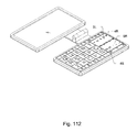
- FIG. 112 is the system in POINT mode
- FIG. 113 is the system in 12-KEY mode
- FIG. 1 shows the structure of the system, where keyboard 3 is displayed as an onscreen keyboard on the touch screen 3 S of a tablet PC. Sub-systems including a software component (not shown) manage the operational aspects of the system. The keyboard is in the uncompressed state.
- FIG. 31 shows the system after the left side of the keyboard is compressed after the user makes a swipe, moving the contact point 0 across the designated left border 4 L.
- the borders of the individual regions defining the keycap areas and the designated borders are also reconfigured according to the compressed state of the keyboard. Repeating the swiping motion brings the left side of the keyboard back to the uncompressed state.
- FIG. 32 shows the system after the right side of the keyboard is compressed after the user makes a swipe, moving the contact point 0 across the designated right border 4 R, from the state of the system shown in FIG. 31 .
- the left side of the keyboard is automatically uncompressed.
- FIG. 33 shows the system after the topside of the keyboard is compressed after the user makes a swipe, moving the contact point 0 across the designated top border 4 T, from the state of the system shown in FIG. 31 .
- FIG. 41 shows the system after the left and right halves of the keyboard are shuffled, or swapped, after the user makes a swipe, moving the contact point 0 across the designated center border 4 C.
- FIG. 42 shows the system after the top and bottom halves of the keyboard are shuffled, or swapped, after the user makes a swipe, moving the contact point 0 across the designated middle border 4 M.
- FIG. 101 shows the structure of the system, where a keyboard 3 comprising a bed of pushbuttons 3 P and a light emitting diode (LED) assembly 3 L are placed under a flexible transparent or translucent touch pad 3 T with a visible or tactile grid 3 G.
- a hinge assembly 1 holds the two halves, display 2 and keyboard 3 , together.
- a software component (not shown) controls the operational aspects of the system. In addition to controlling the basic features, the software component (not shown) allows configuring the system to treat a tap and a click on touch pad 3 T the same or differently, wherein a tap is a touchdown and liftoff of the contact point that does not activate a push button underneath, whereas a click does.
- FIG. 101H shows the structure of the bi-axial hinge assembly 1 where axis 1 X is positioned in line with the X-axis and axis 1 Z is positioned in line with the Z-axis of the standard three dimensional coordinate system with X, Y and Z axes.
- FIG. 102 shows the operational layout of the system.
- the surface of the touch pad 3 T is divided into a grid halve 4 G and a slab halve 4 S.
- the grid halve 4 G has a tactile or visible grid as shown in FIG. 101 , whereas the slab halve 4 S, which also doubles as a pointing device, does not.
- the system can be set to function in CHAR, POINT, or 12-KEY modes. More than one mode can be active at the same time depending on the state of the system.
- FIG. 111 shows the system in CHAR mode where the QWERT halve of the keys are located on the grid halve 4 G and the other halve YUIOP is located on the slab halve 4 S. Both halves of the keypad can be used for data input, but the grid halve 4 G with well defined grids and larger key labels is far more convenient to use than the slab halve 4 S, hence would be primarily used for data input.
- the contact point 0 is located in the grid halve 4 G at this stage.
- FIG. 111A shows the system after the left and right halves of the keyboard are shuffled, or swapped.
- the key labels on the slab halve 4 S and the grid halve 4 G are exchanged by a swipe, moving the contact point 0 across the designated center border 4 C.
- the YUIOP halve is now located on the grid halve 4 G and the QWERT halve on the slab halve 4 S.
- the contact point 0 is now located in the slab halve 4 S.
- FIG. 111E shows the system with display 2 and keyboard 3 rotated to the right side of the hinge assembly 1 .
- FIG. 112 shows the system in POINT mode.
- a swipe across the designated right border 4 R, or an alternative means toggles the pointing device mode of the slab halve 4 S, turning it on in this scenario. While key labels are still displayed on the slab halve 4 S, it no longer functions as a keyboard. It now functions as a touch pad pointing device where sliding across the surface of slab halve 4 S is interpreted as a signal to move the pointer, and a tap or a click, depending on the configuration of the system, on the regions 5 L and 5 R are interpreted as left and right mouse clicks respectively.
- FIG. 113 shows the system in 12-KEY mode.
- the present invention providing a QWERTY style keyboard with large letters on a palm held device, is a preferable alternative to competing approaches employing miniaturization, extension panels or elastic materials. It offers a compact and a reliable design that meets not only the competing, but also the conflicting demands of portability and practicality, imposed upon portable computing devices.
- mapping schemes can also be applied.
- a compact symbol to an elaborate symbol an acronym to a fully expanded description, or a sign to a worded description, for mapping abbreviated to descriptive marks of a core attribute.
- the task of tracking groups of keys in different regions can be made easier by displaying them with a certain shade that migrates together with them as they are being shuffled from one region to another. This would aid the user to recognize them at a glance, similar to how the audience recognizes players of different soccer teams by their uniforms as they move around the field. Different colors, backgrounds, hatchings, styles, or other markings can also be used to achieve a similar effect.
Abstract
An asymmetric keyboard with a QWERTY style layout comprising a plurality of sparse grids and a plurality of dense grids is provided. A sparse grid is substantially large in size containing large keys with large labels, whereas a dense grid is substantially small in size containing small keys with small labels. All keys are functional but the larger keys in the sparse grid offer greater visibility and operability than the smaller keys in the dense grid. The user makes use of the sparse grid as the primary grid to input data. A swipe across a designated boundary interchanges the key labels between corresponding pairs of keys in the designated sparse and dense grids. On the software-based version, a swipe across another designated boundary compresses or decompresses a corresponding grid. On the hardware-based version, a bi-axial hinge allows the display and the keyboard to rotate around two axes.
Description
- This application claims the benefits of provisional applications U.S. 60/857,996 filed Nov. 8, 2006 and U.S. 60/877,599 filed Dec. 29, 2006, and is related to regular application U.S. Ser. No. 11/194,788 filed Aug. 1, 2005, and international application PCT/US2005/027272 filed Aug. 1, 2005.
- The most commonly recognized keyboard from its inception to this day is the QWERTY keyboard. With the advancements in technology, it becomes easier to manufacture portable computing devices varying in size, and the most recognized keyboard just seems to be a logical choice for an input device.
- In general, as a device gets smaller, it becomes more portable, however, less practical to incorporate a keyboard with a QWERTY layout. Various approaches have been attempted to incorporate the standard QWERTY style keyboard, a keyboard layout similar to the standard QWERTY keyboard layout, into portable computing devices including palm held devices, devices small enough to fit into a person's palm.
- Portable computing devices generally fall into two categories: those that incorporate an onscreen keyboard, a keyboard displayed on a touch screen where the input is directed to a designated program, and those that incorporate a physical keyboard.
- The category with an onscreen keyboard ranges from tablet PCs, personal computers with a touch screen, to mobile phones. Since the majority of the portable computing devices that rely on an onscreen keyboard are smaller than the typical full-size QWERTY keyboard at the widest dimension, the user typically has to rely on a stylus to be able to precisely select a key on the relatively smaller onscreen keyboard. Despite this limitation, however, the onscreen keyboard layouts have remained relatively unchanged to this day.
- The category with a physical keyboard ranges from notebook computers to PDAs (personal digital assistants). It appears that more attempts have been made in this category.
- One approach is to use miniaturization to incorporate a QWERTY style keyboard into portable computing devices, however, with a tradeoff in operability. While there are several approaches taken to improve the operability of miniaturized keyboards, such as modifying the shape and orientation of the keys as in U.S. Pat. No. 7,227,536 Griffin et al, or staggering the keys as in U.S. Pat. No. 7,220,069 Griffin et al, they still don't free them from their inherited fundamental deficiency, miniaturization.
- Miniaturized physical keyboards clearly suffer from proportionally scaling down the full-size QWERTY keyboards. The QWERTY keyboard, which is designed for two-handed use, is practical only above a certain size. The keyboard can be scaled down proportionally, but the user's hands cannot be, at least without a considerable amount of difficulty. Therefore, the physical keyboards, when miniaturized, are essentially reduced to “two-thumbed” use, where they are only practical for typing with a person's thumbs. Accordingly, they have become to be known as “thumb-pads.”
- Perhaps, the most glaring deficiency of miniaturized physical keyboards on portable computing devices is highlighted by the common practice of incorporating typing assistant software, which predicts the next letter or series of letters the user would type, saving the user from having to find and press another miniaturized key.
- Another approach is to make the keyboard extendable by use of extension panels as in U.S. Pat. No. 7,206,616 Choi, U.S. Pat. No. 7,221,560 Varela, U.S. Pat. No. 6,707,664 Murphy, U.S. Pat. No. 6,111,527 Susel, and U.S. Pat. No. 5,187,644 Crisan. Some designs have the extension panels rotate out, while others either flip up or pull out. While some of these approaches offer a keyboard nearly as big as a full-size QWERTY keyboard, they are not only bulky and complicated, but also result in serious limitations when applying to palm held devices.
- The keyboards with extension panels installed on notebook computers can offer key sizes comparable to a full-size QWERTY keyboard, but the ones installed on palm held devices end up having keys closer in size to miniaturized keys, due to the physical limitation imposed on the extension panels by the folded size of the palm held device. In general, the portability of a device is inversely proportional to each additional unit of mass, and the added bulk of the extension panels clearly reduce the portability of a device.
- While it looks like an acceptable solution for notebook computers, it doesn't appear to be widely adopted in the industry, probably due to their added bulk, if not weight.
- Yet another approach is to use elastic material, or scissor linkages or alike to hold the individual keys to make the whole keyboard expandable and compressible as in U.S. Pat. No. 5,141,343 Roylance et al., U.S. Pat. No. 5,951,178 Lim, U.S. Pat. No. 6,092,944 Butler, U.S. Pat. No. 7,030,323 Lahr, U.S. Pat. No. 6,882,336 Lahr, U.S. Pat. No. 6,830,397 Lahr, U.S. Pat. No. 6,810,119 Lahr, and U.S. Pat. No. 6,739,774 Lahr. While one approach claims to change the size of the key, in essence it is only giving the perception of a larger key surface area by use of foam or rubber like materials, or a fragmented key surface. These approaches allow changing the spacing between the keys, but despite the variations portrayed in the prior art, the effective core surface area of the keys remain more or less the same.
- There are several deficiencies inherent to this approach. Not only the materials would be difficult to manufacture and maintain, but also the wear and tear would make its operability susceptible to failure. It would also be very difficult, if not impossible, to manufacture scaled down components of this nature to fit into a palm held device. Even if that is possible and the added mass isn't an issue, its reliability and durability would be highly questionable.
- All of these approaches suffer from proportionally scaling down the layout of the full-size QWERTY keyboard and reducing the size of the keys to fit the entire keyboard into a limited surface area. Having a keyboard intended for use with both hands in environments where it is only practical to use one hand results in an inefficient use of the available space. Moreover, it becomes impractical to use the scaled down keyboard due to the substantially small size of the keycaps. A stylus can be used to manipulate the scaled down onscreen keyboard. However, in the majority of cases, holding, using and keeping track of a stylus in such environments can quickly become a burden.
- The primary object of this invention is to provide large keys on a QWERTY style keyboard incorporated into portable computing devices while meeting the conflicting demands of portability and ease-of-use.
- Another object is to factor in the realization that portable computing devices are mostly operated in a one-handed manner, for having to carry it by the other hand, or due to limited access in confined spaces, and optimize the usage of the limited space available for a keyboard on a portable device.
- Yet another object is to have a compact and low maintenance QWERTY style keyboard that is free of a total dependency on miniaturization, extension panels, elastic bands, or complex linkages, on portable computing devices.
- The final object is to deliver a clean design of a QWERTY style keyboard, ideal to be incorporated into portable computing devices for travelers, mobile businesses, and emergency response and law enforcement parties.
- Portable computing devices call for conflicting and competing demands where all things being equal, portability is inversely and ease-of-use is directly proportional to its size.
- Most of the portable computing devices are used only by one hand, yet more precisely by one digit (one finger), while the other hand is used to hold it up. Moreover, in the majority of cases, the keyboard is used only to write short phrases. The proportionally scaled down QWERTY keyboard, onscreen or physical, designed for two-handed use results in an inefficient use of the limited space available on portable computing devices.
- The small keys make it even harder to press when the user is wearing protective gear such as a glove, which makes the contact point of a digit larger than normal, or see with reduced visibility when the user is wearing a facemask, in hazardous environments.
- The proposed invention takes these factors into account and had the QWERTY style layout of the keyboard reorganized to make use of the limited space more efficiently. In contrast to the traditional symmetric layout where the two halves of the keyboard are of comparable sizes and densities, the basic design reorganizes the keyboard into an asymmetric layout where the left and right halves of the keyboard are of different sizes and densities. The key labels are arranged so that those in the dense grid region are substantially small and those in the sparse grid region are substantially large. Alternatively, the top and bottom halves of the keyboard can be arranged in a similar manner, or a combination of both to have more than one dense grid region.
- The asymmetry of the keyboard layout results in a sparse grid region containing keys with a keycap area substantially large enough to be operated with ease by a person's fingertips, and is designated as the primary grid for operating the keyboard. The key assignments are shuffled, or swapped, between the dense and sparse grid regions by a simple swipe across a designated border at the user's discretion. The other key groups in the dense grid regions with substantially smaller keys and labels are functional, but less convenient to operate than the primary group of keys in the sparse grid region. However, they serve as a visual clue positioned in the user's peripheral vision aiding one to retrieve from memory the position of a key on the familiar QWERTY keyboard.
- For devices comparable in size to an average PDA, it offers large keys that a user can comfortably see with their naked eyes and select with a digit under normal circumstances. Not only this approach allows a more natural typing style, but it also eliminates the need for any artificial assistance such as a stylus or typing assistance software.
- For devices substantially larger in size than a PDA, it offers relatively large keycap areas that make it easier to see while wearing a mask, and operated with a fingertip while wearing protective gear.
- The proposed solution not only is free from the burden of additional bulk, weight, complexity, or total dependency on miniaturization, but also offers keys that are actually large. The only mechanical components are the pushbuttons, which are widely and reliably used in many of the palm held devices on the market. It, in fact, can be built without the pushbuttons. The majority of the parts are commonly available electronic components that are proven to be highly reliable and durable in their applications in an extensive range and types of portable computing devices.
- The proposed solution offers a compact, lightweight and reliable design that meets the conflicting and competing demands of portability and ease-of-use imposed on portable computing devices.
- The QWERTY style keyboard is, perhaps, the most widely recognized keyboard. Portable computing devices call for conflicting and competing demands of portability and operability, and incorporating QWERTY style keyboards into portable computing devices have been fraught with a multitude of challenges.
- The QWERTY style keyboards incorporated into portable computing devices generally falls into two categories: onscreen or virtual keyboards, and physical keyboards.
- The onscreen keyboard layouts have remained relatively unchanged. However, they are typically small enough that the user has to resort to using a stylus.
- While there are several approaches taken to improve the physical keyboards, they are usually based upon miniaturized keys, extension panels, or elastic backings. They all suffer from proportionally scaling down the layout of the full-size QWERTY keyboard, and due to the burden of additional bulk, weight, complexity, or total dependency on miniaturization, their operability, reliability and durability is questionable.
- The proposed invention takes into consideration that most of the portable computing devices are used only by one hand, and in the majority of cases, the keyboard is used only to write short phrases. It departs from the trend of emulating the keyboard layout designed for two-handed-use, and employs a reusable space design, offering a keyboard layout designed specifically for one-handed-use.
- An asymmetric keyboard with a QWERTY style layout comprising a number of sparse and dense grids defined in a medium, such as a touch pad or a touch screen, is provided. A sparse grid is substantially large in size containing large keys and labels, and a dense grid is the opposite. All of the keys are functional, however, the larger keys in the sparse grid offer greater visibility and operability than the smaller keys in the dense grid. The user makes use of the sparse grid as the primary grid to input data, while the dense grid remains in the user's peripheral vision acting as a clue to the other side of the familiar QWERTY keyboard layout. An effortless and intuitive shuffling motion, a swipe across a designated common boundary between the sparse and dense grids, interchanges the key labels between the corresponding pairs of keys in the designated sparse and dense grids.
- The proposed design also allows the user to compress and uncompress a corresponding area of the onscreen keyboard with a simple swiping motion across a designated border. The keycap regions and designated borders are automatically reconfigured to match the change in the compression levels of the grids they are associated with.
- The result is a design that offers a compact, lightweight and reliable device that meets the conflicting and competing demands of portable computing devices.
-
FIG. 1 is the structure of the onscreen keyboard -
FIG. 31 is the onscreen keyboard with the left side compressed -
FIG. 32 is the onscreen keyboard with the right side compressed -
FIG. 33 is the onscreen keyboard with the top side compressed -
FIG. 41 is the onscreen keyboard with the left and right halves swapped after a horizontal shuffle -
FIG. 42 is the onscreen keyboard with the top and bottom halves swapped after a vertical shuffle -
FIG. 101 is the structure of the physical keyboard -
FIG. 101H is the structure of the bi-axial hinge system -
FIG. 102 is the operational layout -
FIG. 111 is the system in CHAR mode -
FIG. 111A is the system with the left and right halves of the keyboard swapped after a horizontal shuffle -
FIG. 111B is the system with the two halves of the body rotated to the right side of the hinge assembly -
FIG. 112 is the system in POINT mode -
FIG. 113 is the system in 12-KEY mode -
- 0 Contact point
- 1 Bi-axial hinge
- 1X First axis
- 1Z Second axis
- 2 Display
- 3 Keyboard
- 3G Grid
- 3L Light emitting diode (LED) assembly
- 3P Pushbuttons
- 3S Touch screen
- 3T Touch pad
- 4C Designated center border
- 4G Grid halve
- 4L Designated left border
- 4M Designated middle border
- 4R Designated right border
- 4S Slab halve
- 4T Designated top border
- 5L Mouse left
- 5R Mouse right
-
FIG. 1 shows the structure of the system, wherekeyboard 3 is displayed as an onscreen keyboard on thetouch screen 3S of a tablet PC. Sub-systems including a software component (not shown) manage the operational aspects of the system. The keyboard is in the uncompressed state. -
FIG. 31 shows the system after the left side of the keyboard is compressed after the user makes a swipe, moving thecontact point 0 across the designated leftborder 4L. The borders of the individual regions defining the keycap areas and the designated borders are also reconfigured according to the compressed state of the keyboard. Repeating the swiping motion brings the left side of the keyboard back to the uncompressed state. -
FIG. 32 shows the system after the right side of the keyboard is compressed after the user makes a swipe, moving thecontact point 0 across the designatedright border 4R, from the state of the system shown inFIG. 31 . In the system illustrated, the left side of the keyboard is automatically uncompressed. -
FIG. 33 shows the system after the topside of the keyboard is compressed after the user makes a swipe, moving thecontact point 0 across the designatedtop border 4T, from the state of the system shown inFIG. 31 . -
FIG. 41 shows the system after the left and right halves of the keyboard are shuffled, or swapped, after the user makes a swipe, moving thecontact point 0 across the designatedcenter border 4C. -
FIG. 42 shows the system after the top and bottom halves of the keyboard are shuffled, or swapped, after the user makes a swipe, moving thecontact point 0 across the designatedmiddle border 4M. -
FIG. 101 shows the structure of the system, where akeyboard 3 comprising a bed ofpushbuttons 3P and a light emitting diode (LED)assembly 3L are placed under a flexible transparent ortranslucent touch pad 3T with a visible ortactile grid 3G. Ahinge assembly 1 holds the two halves,display 2 andkeyboard 3, together. A software component (not shown) controls the operational aspects of the system. In addition to controlling the basic features, the software component (not shown) allows configuring the system to treat a tap and a click ontouch pad 3T the same or differently, wherein a tap is a touchdown and liftoff of the contact point that does not activate a push button underneath, whereas a click does. -
FIG. 101H shows the structure of thebi-axial hinge assembly 1 whereaxis 1X is positioned in line with the X-axis andaxis 1Z is positioned in line with the Z-axis of the standard three dimensional coordinate system with X, Y and Z axes. -
FIG. 102 shows the operational layout of the system. The surface of thetouch pad 3T is divided into agrid halve 4G and aslab halve 4S. Thegrid halve 4G has a tactile or visible grid as shown inFIG. 101 , whereas the slab halve 4S, which also doubles as a pointing device, does not. The system can be set to function in CHAR, POINT, or 12-KEY modes. More than one mode can be active at the same time depending on the state of the system. -
FIG. 111 shows the system in CHAR mode where the QWERT halve of the keys are located on the grid halve 4G and the other halve YUIOP is located on the slab halve 4S. Both halves of the keypad can be used for data input, but the grid halve 4G with well defined grids and larger key labels is far more convenient to use than the slab halve 4S, hence would be primarily used for data input. Thecontact point 0, is located in the grid halve 4G at this stage. -
FIG. 111A shows the system after the left and right halves of the keyboard are shuffled, or swapped. The key labels on the slab halve 4S and the grid halve 4G are exchanged by a swipe, moving thecontact point 0 across the designatedcenter border 4C. The YUIOP halve is now located on the grid halve 4G and the QWERT halve on the slab halve 4S. Thecontact point 0 is now located in the slab halve 4S. -
FIG. 111E shows the system withdisplay 2 andkeyboard 3 rotated to the right side of thehinge assembly 1. -
FIG. 112 shows the system in POINT mode. A swipe across the designatedright border 4R, or an alternative means, toggles the pointing device mode of the slab halve 4S, turning it on in this scenario. While key labels are still displayed on the slab halve 4S, it no longer functions as a keyboard. It now functions as a touch pad pointing device where sliding across the surface of slab halve 4S is interpreted as a signal to move the pointer, and a tap or a click, depending on the configuration of the system, on theregions -
FIG. 113 shows the system in 12-KEY mode. - The reader will see that the present invention providing a QWERTY style keyboard with large letters on a palm held device, is a preferable alternative to competing approaches employing miniaturization, extension panels or elastic materials. It offers a compact and a reliable design that meets not only the competing, but also the conflicting demands of portability and practicality, imposed upon portable computing devices.
- While the embodiments illustrated rely on small and large labels respectively for substantially obscure and evident representations of a letter, alternative mapping schemes can also be applied. For example, a compact symbol to an elaborate symbol, an acronym to a fully expanded description, or a sign to a worded description, for mapping abbreviated to descriptive marks of a core attribute.
- The basic principles applied on visual mediums as illustrated in the embodiments, can be easily extended to tactile mediums as well. For example, an asymmetric keyboard with keys incorporating a pinhead array surface similar to a dot-matrix print head where the individual pinheads can be raised or lowered to create a Braille lettering system.
- The task of tracking groups of keys in different regions can be made easier by displaying them with a certain shade that migrates together with them as they are being shuffled from one region to another. This would aid the user to recognize them at a glance, similar to how the audience recognizes players of different soccer teams by their uniforms as they move around the field. Different colors, backgrounds, hatchings, styles, or other markings can also be used to achieve a similar effect.
- While the above description contains many specifications, these should not be construed as a limitation of the scope of the invention, but rather as an exemplification of a few embodiments thereof.
Claims (20)
1. A keyboard for data input comprising:
a) at least one major and one minor key;
b) a set of core symbols wherein each core symbol has a large label and a small label to represent it;
c) a software subsystem in communication with said major and minor keys, and core symbols; and
d) a set of instructions defined within said software subsystem,
wherein said set of instructions is configured to:
i) mark said major key with a large label of an assigned core symbol belonging to said set of core symbols;
ii) mark said minor key with a small label of an assigned core symbol belonging to said set of core symbols;
iii) make each of said major and minor keys represent an attribute corresponding to said assigned core symbol;
iv) interchange said assigned core symbols of said major and minor keys; and
v) make each of said major and minor keys represent an attribute corresponding to said interchanged assigned core symbol.
2. An asymmetric keyboard for data input in claim 1 wherein said keyboard is a virtual keyboard.
3. An asymmetric keyboard for data input in claim 1 wherein said keyboard is a physical keyboard.
4. A computer readable medium encoded with computer readable instructions for a keyboard comprising instructions for:
a) defining at least one major and one minor region in a spatial medium;
b) providing a set of core symbols wherein each core symbol has a descriptive or expanded symbol, and an abbreviated or reduced symbol to represent it;
c) marking said major region with the descriptive or expanded symbol of an assigned core symbol belonging to said set of core symbols;
d) marking said minor regions with the abbreviated or reduced symbol of an assigned core symbol belonging to said set of core symbols;
e) making each of said major and minor regions represent an attribute corresponding to said assigned core symbol; and
g) detecting an interchange signal,
wherein said set of instructions interchange said assigned core symbols of said major and minor regions on detecting said interchange signal.
5. A computer readable medium encoded with computer readable instructions for a keyboard in claim 4 wherein said major regions is larger than said minor region.
6. A computer readable medium encoded with computer readable instructions for a keyboard in claim 4 wherein said computer readable medium is a carrier.
7. A computer readable medium encoded with computer readable instructions for a keyboard in claim 4 wherein said computer readable medium is volatile.
8. A computer readable medium encoded with computer readable instructions for a keyboard in claim 4 wherein said computer readable medium is nonvolatile.
9. A computer readable medium encoded with computer readable instructions for an asymmetric keyboard in claim 4 wherein said spatial medium allows tactile input.
10. A computer readable medium encoded with computer readable instructions for an asymmetric keyboard in claim 4 wherein said spatial medium provides visual feedback.
11. A computer readable medium encoded with computer readable instructions for an asymmetric keyboard in claim 4 wherein said spatial medium provides tactile feedback.
12. A computer readable medium encoded with computer readable instructions for changing the state of a set of regions configured for:
a) defining said set of regions in a spatial medium by a set of spatial boundaries;
b) tracking the state of an object in said spatial medium;
c) generating a traversal signal when said object traverses a designated boundary which is a member of said set of spatial boundaries; and
d) defining and maintaining a first and a second states of said set of regions,
wherein said instructions change said state of said set of regions from said first to second state when said traversal signal is detected.
13. A computer readable medium encoded with computer readable instructions for changing the state of a set of regions in claim 12 wherein:
a) said first state is a first definition of said set of spatial boundaries; and
b) said second state is a second definition of said set of spatial boundaries.
14. A computer readable medium encoded with computer readable instructions for changing the state of a set of regions in claim 12 further comprising an interpreter for translating said state of said object in said spatial medium into a signal to control a pointer wherein:
a) said first state is the state where said interpreter is active; and
b) said second state is the state where said interpreter is inactive.
15. A computer readable medium encoded with computer readable instructions for changing the state of a set of regions in claim 12 wherein said computer readable medium is a carrier.
16. A computer readable medium encoded with computer readable instructions for changing the state of a set of regions in claim 12 wherein said computer readable medium is volatile.
17. A computer readable medium encoded with computer readable instructions for changing the state of a set of regions in claim 12 wherein said computer readable medium is nonvolatile.
18. A bi-axial hinge mechanism comprising:
a) a first hinge mechanism allowing a set of attached branches to rotate around a first axis; and
b) a second hinge mechanism on each of said set of attached branches allowing an attached leaf component to rotate around a second axis which is perpendicular to said first axis,
thereby allowing each of said leaf components to rotate around said first and second axes.
19. A bi-axial hinge mechanism in claim 18 wherein said set of attached branches consists of two members, a first and a second attached branches.
20. A bi-axial hinge mechanism in claim 19 wherein:
a) said attached leaf component of said first attached branch is a display device; and
b) said attached leaf component of said second attached branch is an input device.
Priority Applications (2)
| Application Number | Priority Date | Filing Date | Title |
|---|---|---|---|
| US12/440,468 US9152238B2 (en) | 2005-08-01 | 2007-10-25 | Asymmetric shuffle keyboard |
| US14/833,446 US20160231927A1 (en) | 2005-08-01 | 2015-08-24 | Asymmetric Shuffle Keyboard |
Applications Claiming Priority (5)
| Application Number | Priority Date | Filing Date | Title |
|---|---|---|---|
| US11/194,788 US8797192B2 (en) | 2004-08-16 | 2005-08-01 | Virtual keypad input device |
| US85799606P | 2006-11-08 | 2006-11-08 | |
| US87759906P | 2006-12-29 | 2006-12-29 | |
| PCT/US2007/082513 WO2008057785A2 (en) | 2006-11-08 | 2007-10-25 | Asymmetric shuffle keyboard |
| US12/440,468 US9152238B2 (en) | 2005-08-01 | 2007-10-25 | Asymmetric shuffle keyboard |
Publications (2)
| Publication Number | Publication Date |
|---|---|
| US20100110012A1 true US20100110012A1 (en) | 2010-05-06 |
| US9152238B2 US9152238B2 (en) | 2015-10-06 |
Family
ID=39365199
Family Applications (2)
| Application Number | Title | Priority Date | Filing Date |
|---|---|---|---|
| US12/440,468 Active 2030-09-05 US9152238B2 (en) | 2005-08-01 | 2007-10-25 | Asymmetric shuffle keyboard |
| US14/833,446 Abandoned US20160231927A1 (en) | 2005-08-01 | 2015-08-24 | Asymmetric Shuffle Keyboard |
Family Applications After (1)
| Application Number | Title | Priority Date | Filing Date |
|---|---|---|---|
| US14/833,446 Abandoned US20160231927A1 (en) | 2005-08-01 | 2015-08-24 | Asymmetric Shuffle Keyboard |
Country Status (4)
| Country | Link |
|---|---|
| US (2) | US9152238B2 (en) |
| EP (1) | EP2092405A4 (en) |
| KR (1) | KR20090098967A (en) |
| WO (1) | WO2008057785A2 (en) |
Cited By (11)
| Publication number | Priority date | Publication date | Assignee | Title |
|---|---|---|---|---|
| US20110078567A1 (en) * | 2009-09-30 | 2011-03-31 | Pantech Co., Ltd. | Apparatus and method for providing virtual keyboard |
| US20110181535A1 (en) * | 2010-01-27 | 2011-07-28 | Kyocera Corporation | Portable electronic device and method of controlling device |
| US20110285631A1 (en) * | 2010-05-21 | 2011-11-24 | Kabushiki Kaisha Toshiba | Information processing apparatus and method of displaying a virtual keyboard |
| US20120047454A1 (en) * | 2010-08-18 | 2012-02-23 | Erik Anthony Harte | Dynamic Soft Input |
| US8665233B2 (en) * | 2010-07-22 | 2014-03-04 | Samsung Electronics Co., Ltd. | Input device and control method thereof |
| US20150026639A1 (en) * | 2013-07-19 | 2015-01-22 | Fuji Xerox Co., Ltd. | Information processing apparatus and method, and non-transitory computer readable medium |
| JPWO2013024526A1 (en) * | 2011-08-15 | 2015-03-05 | 富士通株式会社 | Portable electronic device and key display program |
| US9086775B1 (en) * | 2008-07-10 | 2015-07-21 | Google Inc. | Minimizing software based keyboard |
| US20160092047A1 (en) * | 2014-09-29 | 2016-03-31 | Samsung Electronics Co., Ltd. | Display apparatus and method for displaying a screen in display apparatus |
| US20160231927A1 (en) * | 2005-08-01 | 2016-08-11 | Cubic Design Studios Llc | Asymmetric Shuffle Keyboard |
| WO2017105008A1 (en) * | 2015-12-17 | 2017-06-22 | Samsung Electronics Co., Ltd. | Electronic device for providing character input function and method for controlling thereof |
Families Citing this family (23)
| Publication number | Priority date | Publication date | Assignee | Title |
|---|---|---|---|---|
| NO328721B1 (en) * | 2008-05-02 | 2010-05-03 | Filophone Electronics As | Input Device |
| US8279174B2 (en) * | 2008-08-27 | 2012-10-02 | Lg Electronics Inc. | Display device and method of controlling the display device |
| JP5487679B2 (en) * | 2009-03-31 | 2014-05-07 | ソニー株式会社 | Information processing apparatus, information processing method, and information processing program |
| US8591128B2 (en) | 2009-07-01 | 2013-11-26 | Nokia Corporation | Extendable mechanism |
| US8627224B2 (en) | 2009-10-27 | 2014-01-07 | Qualcomm Incorporated | Touch screen keypad layout |
| US8490008B2 (en) | 2011-11-10 | 2013-07-16 | Research In Motion Limited | Touchscreen keyboard predictive display and generation of a set of characters |
| US9652448B2 (en) | 2011-11-10 | 2017-05-16 | Blackberry Limited | Methods and systems for removing or replacing on-keyboard prediction candidates |
| US9310889B2 (en) | 2011-11-10 | 2016-04-12 | Blackberry Limited | Touchscreen keyboard predictive display and generation of a set of characters |
| US9122672B2 (en) | 2011-11-10 | 2015-09-01 | Blackberry Limited | In-letter word prediction for virtual keyboard |
| US9715489B2 (en) | 2011-11-10 | 2017-07-25 | Blackberry Limited | Displaying a prediction candidate after a typing mistake |
| US9152323B2 (en) | 2012-01-19 | 2015-10-06 | Blackberry Limited | Virtual keyboard providing an indication of received input |
| US9557913B2 (en) | 2012-01-19 | 2017-01-31 | Blackberry Limited | Virtual keyboard display having a ticker proximate to the virtual keyboard |
| WO2013123572A1 (en) | 2012-02-24 | 2013-08-29 | Research In Motion Limited | Touchscreen keyboard providing word predictions in partitions of the touchscreen keyboard in proximate association with candidate letters |
| US20130222255A1 (en) * | 2012-02-24 | 2013-08-29 | Research In Motion Limited | Portable electronic device including touch-sensitive display and method of controlling same |
| US9201510B2 (en) | 2012-04-16 | 2015-12-01 | Blackberry Limited | Method and device having touchscreen keyboard with visual cues |
| US9292192B2 (en) | 2012-04-30 | 2016-03-22 | Blackberry Limited | Method and apparatus for text selection |
| US9354805B2 (en) | 2012-04-30 | 2016-05-31 | Blackberry Limited | Method and apparatus for text selection |
| US9207860B2 (en) | 2012-05-25 | 2015-12-08 | Blackberry Limited | Method and apparatus for detecting a gesture |
| US9116552B2 (en) | 2012-06-27 | 2015-08-25 | Blackberry Limited | Touchscreen keyboard providing selection of word predictions in partitions of the touchscreen keyboard |
| US9063653B2 (en) | 2012-08-31 | 2015-06-23 | Blackberry Limited | Ranking predictions based on typing speed and typing confidence |
| US9524290B2 (en) | 2012-08-31 | 2016-12-20 | Blackberry Limited | Scoring predictions based on prediction length and typing speed |
| US20140208263A1 (en) * | 2013-01-24 | 2014-07-24 | Victor Maklouf | System and method for dynamically displaying characters over a screen of a computerized mobile device |
| KR102206385B1 (en) | 2014-04-11 | 2021-01-22 | 엘지전자 주식회사 | Mobile terminal and method for controlling the same |
Citations (28)
| Publication number | Priority date | Publication date | Assignee | Title |
|---|---|---|---|---|
| US5579037A (en) * | 1993-06-29 | 1996-11-26 | International Business Machines Corporation | Method and system for selecting objects on a tablet display using a pen-like interface |
| US6073036A (en) * | 1997-04-28 | 2000-06-06 | Nokia Mobile Phones Limited | Mobile station with touch input having automatic symbol magnification function |
| US6169538B1 (en) * | 1998-08-13 | 2001-01-02 | Motorola, Inc. | Method and apparatus for implementing a graphical user interface keyboard and a text buffer on electronic devices |
| US6271835B1 (en) * | 1998-09-03 | 2001-08-07 | Nortel Networks Limited | Touch-screen input device |
| US20020174183A1 (en) * | 2001-04-04 | 2002-11-21 | Babak Saeidi | System and method for identifying information |
| US20030080945A1 (en) * | 2001-10-29 | 2003-05-01 | Betts-Lacroix Jonathan | Keyboard with variable-sized keys |
| US20040118751A1 (en) * | 2002-12-24 | 2004-06-24 | Wagner Jon P. | Multicomponent sorption bed for the desulfurization of hydrocarbons |
| US20050020325A1 (en) * | 2003-07-24 | 2005-01-27 | Motorola, Inc. | Multi-configuration portable electronic device and method for operating the same |
| US20050030292A1 (en) * | 2001-12-12 | 2005-02-10 | Diederiks Elmo Marcus Attila | Display system with tactile guidance |
| US20050071778A1 (en) * | 2003-09-26 | 2005-03-31 | Nokia Corporation | Method for dynamic key size prediction with touch displays and an electronic device using the method |
| US20050243069A1 (en) * | 2004-04-30 | 2005-11-03 | Rudy Yorio | Display-input apparatus for a multi-configuration portable device |
| US20060033723A1 (en) * | 2004-08-16 | 2006-02-16 | Wai-Lin Maw | Virtual keypad input device |
| US20060135225A1 (en) * | 2004-12-22 | 2006-06-22 | Chi-Hsiung Lin | Handheld electronic data processing device |
| US20060161846A1 (en) * | 2002-11-29 | 2006-07-20 | Koninklijke Philips Electronics N.V. | User interface with displaced representation of touch area |
| US20060190836A1 (en) * | 2005-02-23 | 2006-08-24 | Wei Ling Su | Method and apparatus for data entry input |
| US20060197753A1 (en) * | 2005-03-04 | 2006-09-07 | Hotelling Steven P | Multi-functional hand-held device |
| US7117009B2 (en) * | 2002-12-20 | 2006-10-03 | Motorola, Inc. | Apparatus and method for electronic device control |
| US7136687B2 (en) * | 2004-12-16 | 2006-11-14 | Chi Mei Communication Systems, Inc. | Electrical device for adjusting the angle between a top module and a bottom module |
| US7286861B2 (en) * | 2003-12-10 | 2007-10-23 | Curitel Communications, Inc. | Rotary folder-type mobile communication terminal |
| US20080024451A1 (en) * | 2006-07-27 | 2008-01-31 | Satoru Aimi | Remote input device and electronic apparatus using the same |
| US7346375B2 (en) * | 2003-10-24 | 2008-03-18 | Mitsubishi Steel Mfg. Co., Ltd. | Rotating mechanism of biaxial hinge and portable telephone with the same |
| US20080096610A1 (en) * | 2006-10-20 | 2008-04-24 | Samsung Electronics Co., Ltd. | Text input method and mobile terminal therefor |
| US7419099B2 (en) * | 2003-10-17 | 2008-09-02 | Samsung Electronics Co., Ltd. | Portable terminal and swing hinge module thereof |
| US20080284744A1 (en) * | 2007-05-14 | 2008-11-20 | Samsung Electronics Co. Ltd. | Method and apparatus for inputting characters in a mobile communication terminal |
| US7602378B2 (en) * | 2006-10-26 | 2009-10-13 | Apple Inc. | Method, system, and graphical user interface for selecting a soft keyboard |
| US7694231B2 (en) * | 2006-01-05 | 2010-04-06 | Apple Inc. | Keyboards for portable electronic devices |
| US7797026B2 (en) * | 2004-11-19 | 2010-09-14 | Lite-On Technology Corporation | Portable electric device |
| US7844050B2 (en) * | 2004-08-28 | 2010-11-30 | Samsung Electronics Co., Ltd. | Biaxial hinge device for mobile terminal and mounting mechanism thereof |
Family Cites Families (5)
| Publication number | Priority date | Publication date | Assignee | Title |
|---|---|---|---|---|
| US20040119751A1 (en) * | 2002-08-07 | 2004-06-24 | Minolta Co., Ltd. | Data input device, image processing device, data input method and computer readable recording medium on which data input program is recorded |
| CN2745286Y (en) | 2004-11-18 | 2005-12-07 | 鸿富锦精密工业(深圳)有限公司 | Folding handset |
| KR20110127248A (en) * | 2006-09-28 | 2011-11-24 | 교세라 가부시키가이샤 | Apparatus with touch panel and control method therefor |
| EP2092405A4 (en) * | 2006-11-08 | 2012-10-17 | Cubic Design Studios Llc | Asymmetric shuffle keyboard |
| KR101515064B1 (en) * | 2007-09-04 | 2015-04-24 | 삼성전자주식회사 | Portable terminal and method for displaying touch keypad thereof |
-
2007
- 2007-10-25 EP EP07863506A patent/EP2092405A4/en not_active Withdrawn
- 2007-10-25 KR KR1020097011828A patent/KR20090098967A/en not_active Application Discontinuation
- 2007-10-25 WO PCT/US2007/082513 patent/WO2008057785A2/en active Application Filing
- 2007-10-25 US US12/440,468 patent/US9152238B2/en active Active
-
2015
- 2015-08-24 US US14/833,446 patent/US20160231927A1/en not_active Abandoned
Patent Citations (29)
| Publication number | Priority date | Publication date | Assignee | Title |
|---|---|---|---|---|
| US5579037A (en) * | 1993-06-29 | 1996-11-26 | International Business Machines Corporation | Method and system for selecting objects on a tablet display using a pen-like interface |
| US6073036A (en) * | 1997-04-28 | 2000-06-06 | Nokia Mobile Phones Limited | Mobile station with touch input having automatic symbol magnification function |
| US6169538B1 (en) * | 1998-08-13 | 2001-01-02 | Motorola, Inc. | Method and apparatus for implementing a graphical user interface keyboard and a text buffer on electronic devices |
| US6271835B1 (en) * | 1998-09-03 | 2001-08-07 | Nortel Networks Limited | Touch-screen input device |
| US20020174183A1 (en) * | 2001-04-04 | 2002-11-21 | Babak Saeidi | System and method for identifying information |
| US7372454B2 (en) * | 2001-10-29 | 2008-05-13 | Oqo Incorporated | Keyboard with variable-sized keys |
| US20030080945A1 (en) * | 2001-10-29 | 2003-05-01 | Betts-Lacroix Jonathan | Keyboard with variable-sized keys |
| US20050030292A1 (en) * | 2001-12-12 | 2005-02-10 | Diederiks Elmo Marcus Attila | Display system with tactile guidance |
| US20060161846A1 (en) * | 2002-11-29 | 2006-07-20 | Koninklijke Philips Electronics N.V. | User interface with displaced representation of touch area |
| US7117009B2 (en) * | 2002-12-20 | 2006-10-03 | Motorola, Inc. | Apparatus and method for electronic device control |
| US20040118751A1 (en) * | 2002-12-24 | 2004-06-24 | Wagner Jon P. | Multicomponent sorption bed for the desulfurization of hydrocarbons |
| US20050020325A1 (en) * | 2003-07-24 | 2005-01-27 | Motorola, Inc. | Multi-configuration portable electronic device and method for operating the same |
| US20050071778A1 (en) * | 2003-09-26 | 2005-03-31 | Nokia Corporation | Method for dynamic key size prediction with touch displays and an electronic device using the method |
| US7419099B2 (en) * | 2003-10-17 | 2008-09-02 | Samsung Electronics Co., Ltd. | Portable terminal and swing hinge module thereof |
| US7346375B2 (en) * | 2003-10-24 | 2008-03-18 | Mitsubishi Steel Mfg. Co., Ltd. | Rotating mechanism of biaxial hinge and portable telephone with the same |
| US7286861B2 (en) * | 2003-12-10 | 2007-10-23 | Curitel Communications, Inc. | Rotary folder-type mobile communication terminal |
| US20050243069A1 (en) * | 2004-04-30 | 2005-11-03 | Rudy Yorio | Display-input apparatus for a multi-configuration portable device |
| US20060033723A1 (en) * | 2004-08-16 | 2006-02-16 | Wai-Lin Maw | Virtual keypad input device |
| US7844050B2 (en) * | 2004-08-28 | 2010-11-30 | Samsung Electronics Co., Ltd. | Biaxial hinge device for mobile terminal and mounting mechanism thereof |
| US7797026B2 (en) * | 2004-11-19 | 2010-09-14 | Lite-On Technology Corporation | Portable electric device |
| US7136687B2 (en) * | 2004-12-16 | 2006-11-14 | Chi Mei Communication Systems, Inc. | Electrical device for adjusting the angle between a top module and a bottom module |
| US20060135225A1 (en) * | 2004-12-22 | 2006-06-22 | Chi-Hsiung Lin | Handheld electronic data processing device |
| US20060190836A1 (en) * | 2005-02-23 | 2006-08-24 | Wei Ling Su | Method and apparatus for data entry input |
| US20060197753A1 (en) * | 2005-03-04 | 2006-09-07 | Hotelling Steven P | Multi-functional hand-held device |
| US7694231B2 (en) * | 2006-01-05 | 2010-04-06 | Apple Inc. | Keyboards for portable electronic devices |
| US20080024451A1 (en) * | 2006-07-27 | 2008-01-31 | Satoru Aimi | Remote input device and electronic apparatus using the same |
| US20080096610A1 (en) * | 2006-10-20 | 2008-04-24 | Samsung Electronics Co., Ltd. | Text input method and mobile terminal therefor |
| US7602378B2 (en) * | 2006-10-26 | 2009-10-13 | Apple Inc. | Method, system, and graphical user interface for selecting a soft keyboard |
| US20080284744A1 (en) * | 2007-05-14 | 2008-11-20 | Samsung Electronics Co. Ltd. | Method and apparatus for inputting characters in a mobile communication terminal |
Cited By (18)
| Publication number | Priority date | Publication date | Assignee | Title |
|---|---|---|---|---|
| US20160231927A1 (en) * | 2005-08-01 | 2016-08-11 | Cubic Design Studios Llc | Asymmetric Shuffle Keyboard |
| US11941244B1 (en) | 2008-07-10 | 2024-03-26 | Google Llc | Presenting suggestions from search corpora |
| US9086775B1 (en) * | 2008-07-10 | 2015-07-21 | Google Inc. | Minimizing software based keyboard |
| US11461003B1 (en) | 2008-07-10 | 2022-10-04 | Google Llc | User interface for presenting suggestions from a local search corpus |
| US10678429B1 (en) | 2008-07-10 | 2020-06-09 | Google Llc | Native search application providing search results of multiple search types |
| US9933938B1 (en) * | 2008-07-10 | 2018-04-03 | Google Llc | Minimizing software based keyboard |
| US20110078567A1 (en) * | 2009-09-30 | 2011-03-31 | Pantech Co., Ltd. | Apparatus and method for providing virtual keyboard |
| US20110181535A1 (en) * | 2010-01-27 | 2011-07-28 | Kyocera Corporation | Portable electronic device and method of controlling device |
| US20110285631A1 (en) * | 2010-05-21 | 2011-11-24 | Kabushiki Kaisha Toshiba | Information processing apparatus and method of displaying a virtual keyboard |
| US8665233B2 (en) * | 2010-07-22 | 2014-03-04 | Samsung Electronics Co., Ltd. | Input device and control method thereof |
| US20120047454A1 (en) * | 2010-08-18 | 2012-02-23 | Erik Anthony Harte | Dynamic Soft Input |
| JPWO2013024526A1 (en) * | 2011-08-15 | 2015-03-05 | 富士通株式会社 | Portable electronic device and key display program |
| US9965144B2 (en) * | 2013-07-19 | 2018-05-08 | Fuji Xerox Co., Ltd. | Information processing apparatus and method, and non-transitory computer readable medium |
| US20150026639A1 (en) * | 2013-07-19 | 2015-01-22 | Fuji Xerox Co., Ltd. | Information processing apparatus and method, and non-transitory computer readable medium |
| US10656790B2 (en) * | 2014-09-29 | 2020-05-19 | Samsung Electronics Co., Ltd. | Display apparatus and method for displaying a screen in display apparatus |
| US20160092047A1 (en) * | 2014-09-29 | 2016-03-31 | Samsung Electronics Co., Ltd. | Display apparatus and method for displaying a screen in display apparatus |
| WO2017105008A1 (en) * | 2015-12-17 | 2017-06-22 | Samsung Electronics Co., Ltd. | Electronic device for providing character input function and method for controlling thereof |
| US10782876B2 (en) | 2015-12-17 | 2020-09-22 | Samsung Electronics Co., Ltd. | Electronic device for providing character input function and method for controlling thereof |
Also Published As
| Publication number | Publication date |
|---|---|
| WO2008057785A2 (en) | 2008-05-15 |
| KR20090098967A (en) | 2009-09-18 |
| WO2008057785A3 (en) | 2008-12-04 |
| US9152238B2 (en) | 2015-10-06 |
| US20160231927A1 (en) | 2016-08-11 |
| EP2092405A2 (en) | 2009-08-26 |
| EP2092405A4 (en) | 2012-10-17 |
Similar Documents
| Publication | Publication Date | Title |
|---|---|---|
| US9152238B2 (en) | Asymmetric shuffle keyboard | |
| US7986985B2 (en) | Portable electronic device with a sliding mechanism for a component thereof | |
| US8130199B2 (en) | Compact universal keyboard | |
| US5861823A (en) | Data entry device having multifunction keys | |
| US6657560B1 (en) | Rounded keypad | |
| US6107997A (en) | Touch-sensitive keyboard/mouse and computing device using the same | |
| US20080252603A1 (en) | Condensed Keyboard for Electronic Devices | |
| US7859830B2 (en) | Mobile quick-keying device | |
| WO1999037025A1 (en) | Data entry device having multifunction keys | |
| JP2004032548A (en) | Mobile terminal | |
| CN202563450U (en) | Mouse and keyboard integrated device | |
| Mehring et al. | KITTY: Keyboard independent touch typing in VR | |
| RU2214619C2 (en) | Keyboard, key, method for character output and change using electronic-device keyboard keys | |
| US20040069600A1 (en) | Keyboard and apparatus comprising the same | |
| JP2004220536A (en) | Input device for information processor | |
| CN101589355A (en) | Asymmetric shuffle keyboard | |
| CA2699299A1 (en) | Asymmetric shuffle keyboard | |
| WO2008047172A2 (en) | Glove as computer control input unit | |
| US6398437B1 (en) | Keyboard and computer | |
| CN102495685A (en) | Data input and mouse locating device of computer | |
| JP2003273995A (en) | Portable device | |
| US20200150779A1 (en) | Keyboard | |
| WO2020212866A1 (en) | Handheld controller device | |
| Rathod et al. | Touchpad: A versatile Input Device | |
| Yoon et al. | Square: 3x3 keypad mapped to geometric elements of a square |
Legal Events
| Date | Code | Title | Description |
|---|---|---|---|
| STCF | Information on status: patent grant |
Free format text: PATENTED CASE |
|
| MAFP | Maintenance fee payment |
Free format text: PAYMENT OF MAINTENANCE FEE, 4TH YR, SMALL ENTITY (ORIGINAL EVENT CODE: M2551); ENTITY STATUS OF PATENT OWNER: SMALL ENTITY Year of fee payment: 4 |
|
| MAFP | Maintenance fee payment |
Free format text: PAYMENT OF MAINTENANCE FEE, 8TH YR, SMALL ENTITY (ORIGINAL EVENT CODE: M2552); ENTITY STATUS OF PATENT OWNER: SMALL ENTITY Year of fee payment: 8 |