US20080109061A1 - Adjustable bifurcation catheter incorporating electroactive polymer and methods of making and using the same - Google Patents
Adjustable bifurcation catheter incorporating electroactive polymer and methods of making and using the same Download PDFInfo
- Publication number
- US20080109061A1 US20080109061A1 US11/591,848 US59184806A US2008109061A1 US 20080109061 A1 US20080109061 A1 US 20080109061A1 US 59184806 A US59184806 A US 59184806A US 2008109061 A1 US2008109061 A1 US 2008109061A1
- Authority
- US
- United States
- Prior art keywords
- eap
- catheter
- electrical configuration
- electrical
- assembly
- Prior art date
- Legal status (The legal status is an assumption and is not a legal conclusion. Google has not performed a legal analysis and makes no representation as to the accuracy of the status listed.)
- Granted
Links
- 0 *C1=C(C)NC(C)=C1.CC1=C2OCCOC2=C(C)S1.[1*]C1=C(/C=C/C)C=C([2*])C(C)=C1.[H]N(C)C1=CC=C(C)C=C1.[H]N1C(C)=CC=C1C Chemical compound *C1=C(C)NC(C)=C1.CC1=C2OCCOC2=C(C)S1.[1*]C1=C(/C=C/C)C=C([2*])C(C)=C1.[H]N(C)C1=CC=C(C)C=C1.[H]N1C(C)=CC=C1C 0.000 description 2
- CDBMLCHWSOVELK-UHFFFAOYSA-N CC(C)(C)c1c2OCCOc2c(C)[s]1 Chemical compound CC(C)(C)c1c2OCCOc2c(C)[s]1 CDBMLCHWSOVELK-UHFFFAOYSA-N 0.000 description 1
- MYWZUWQSOOTKRX-UHFFFAOYSA-N CC1=CC=C(C)N1.CC1=CC=C(C)N1 Chemical compound CC1=CC=C(C)N1.CC1=CC=C(C)N1 MYWZUWQSOOTKRX-UHFFFAOYSA-N 0.000 description 1
- QCIFLGSATTWUQJ-UHFFFAOYSA-N Cc(cc1)ccc1NC Chemical compound Cc(cc1)ccc1NC QCIFLGSATTWUQJ-UHFFFAOYSA-N 0.000 description 1
- XILGXSYEQPUUEW-UHFFFAOYSA-N [H]N1C(C)=CC=C1C1=CC=C(C2=CC=C(C3=CC=C(C4=CC=C(C5=CC=C(C6=CC=C(C7=CC=C(C)N7[H])N6[H])N5[H])N4[H])N3[H])N2[H])N1[H] Chemical compound [H]N1C(C)=CC=C1C1=CC=C(C2=CC=C(C3=CC=C(C4=CC=C(C5=CC=C(C6=CC=C(C7=CC=C(C)N7[H])N6[H])N5[H])N4[H])N3[H])N2[H])N1[H] XILGXSYEQPUUEW-UHFFFAOYSA-N 0.000 description 1
Images


Classifications
-
- A—HUMAN NECESSITIES
- A61—MEDICAL OR VETERINARY SCIENCE; HYGIENE
- A61M—DEVICES FOR INTRODUCING MEDIA INTO, OR ONTO, THE BODY; DEVICES FOR TRANSDUCING BODY MEDIA OR FOR TAKING MEDIA FROM THE BODY; DEVICES FOR PRODUCING OR ENDING SLEEP OR STUPOR
- A61M25/00—Catheters; Hollow probes
- A61M25/10—Balloon catheters
-
- A—HUMAN NECESSITIES
- A61—MEDICAL OR VETERINARY SCIENCE; HYGIENE
- A61F—FILTERS IMPLANTABLE INTO BLOOD VESSELS; PROSTHESES; DEVICES PROVIDING PATENCY TO, OR PREVENTING COLLAPSING OF, TUBULAR STRUCTURES OF THE BODY, e.g. STENTS; ORTHOPAEDIC, NURSING OR CONTRACEPTIVE DEVICES; FOMENTATION; TREATMENT OR PROTECTION OF EYES OR EARS; BANDAGES, DRESSINGS OR ABSORBENT PADS; FIRST-AID KITS
- A61F2/00—Filters implantable into blood vessels; Prostheses, i.e. artificial substitutes or replacements for parts of the body; Appliances for connecting them with the body; Devices providing patency to, or preventing collapsing of, tubular structures of the body, e.g. stents
- A61F2/95—Instruments specially adapted for placement or removal of stents or stent-grafts
- A61F2/958—Inflatable balloons for placing stents or stent-grafts
-
- A—HUMAN NECESSITIES
- A61—MEDICAL OR VETERINARY SCIENCE; HYGIENE
- A61M—DEVICES FOR INTRODUCING MEDIA INTO, OR ONTO, THE BODY; DEVICES FOR TRANSDUCING BODY MEDIA OR FOR TAKING MEDIA FROM THE BODY; DEVICES FOR PRODUCING OR ENDING SLEEP OR STUPOR
- A61M25/00—Catheters; Hollow probes
- A61M25/10—Balloon catheters
- A61M25/1027—Making of balloon catheters
-
- A—HUMAN NECESSITIES
- A61—MEDICAL OR VETERINARY SCIENCE; HYGIENE
- A61M—DEVICES FOR INTRODUCING MEDIA INTO, OR ONTO, THE BODY; DEVICES FOR TRANSDUCING BODY MEDIA OR FOR TAKING MEDIA FROM THE BODY; DEVICES FOR PRODUCING OR ENDING SLEEP OR STUPOR
- A61M25/00—Catheters; Hollow probes
- A61M25/0043—Catheters; Hollow probes characterised by structural features
- A61M2025/0058—Catheters; Hollow probes characterised by structural features having an electroactive polymer material, e.g. for steering purposes, for control of flexibility, for locking, for opening or closing
-
- A—HUMAN NECESSITIES
- A61—MEDICAL OR VETERINARY SCIENCE; HYGIENE
- A61M—DEVICES FOR INTRODUCING MEDIA INTO, OR ONTO, THE BODY; DEVICES FOR TRANSDUCING BODY MEDIA OR FOR TAKING MEDIA FROM THE BODY; DEVICES FOR PRODUCING OR ENDING SLEEP OR STUPOR
- A61M25/00—Catheters; Hollow probes
- A61M25/10—Balloon catheters
- A61M2025/1043—Balloon catheters with special features or adapted for special applications
- A61M2025/1045—Balloon catheters with special features or adapted for special applications for treating bifurcations, e.g. balloons in y-configuration, separate balloons or special features of the catheter for treating bifurcations
-
- A—HUMAN NECESSITIES
- A61—MEDICAL OR VETERINARY SCIENCE; HYGIENE
- A61M—DEVICES FOR INTRODUCING MEDIA INTO, OR ONTO, THE BODY; DEVICES FOR TRANSDUCING BODY MEDIA OR FOR TAKING MEDIA FROM THE BODY; DEVICES FOR PRODUCING OR ENDING SLEEP OR STUPOR
- A61M25/00—Catheters; Hollow probes
- A61M25/10—Balloon catheters
- A61M2025/1043—Balloon catheters with special features or adapted for special applications
- A61M2025/1088—Balloon catheters with special features or adapted for special applications having special surface characteristics depending on material properties or added substances, e.g. for reducing friction
-
- A—HUMAN NECESSITIES
- A61—MEDICAL OR VETERINARY SCIENCE; HYGIENE
- A61M—DEVICES FOR INTRODUCING MEDIA INTO, OR ONTO, THE BODY; DEVICES FOR TRANSDUCING BODY MEDIA OR FOR TAKING MEDIA FROM THE BODY; DEVICES FOR PRODUCING OR ENDING SLEEP OR STUPOR
- A61M25/00—Catheters; Hollow probes
- A61M25/01—Introducing, guiding, advancing, emplacing or holding catheters
- A61M25/0105—Steering means as part of the catheter or advancing means; Markers for positioning
- A61M25/0133—Tip steering devices
- A61M25/0158—Tip steering devices with magnetic or electrical means, e.g. by using piezo materials, electroactive polymers, magnetic materials or by heating of shape memory materials
Abstract
Description
- The present invention relates to the field of medical catheters, in particular, medical catheters employing electroactive polymers.
- Balloon catheters, having expandable balloon members located at the distal end of the balloon catheter, are employed in a variety of medical procedures. These procedures include using balloons as dilatation devices for compressing atherosclerotic plaque which results in a narrowing of the arterial lumen. They also include using balloons for delivery and expansion of prosthetic devices such as stents, to a lesion site, i.e. vessel obstruction, within a body vessel.
- One medical procedure where balloon catheters are employed is percutaneous transluminal coronary angioplasty, or balloon angioplasty, which is a non-invasive, non-surgical means of treating peripheral and coronary arteries. This technique consists of inserting an uninflated balloon catheter into the affected artery. Dilation of the diseased segment of artery is accomplished by inflating the balloon which pushes the atherosclerotic lesion outward, thereby enlarging the arterial diameter.
- In the most widely used form of angioplasty, a balloon catheter is guided through the vascular system until the balloon, which is carried at the distal end of a catheter shaft is positioned across the stenosis or lesion, i.e., vessel obstruction. An expandable stent can be included on the balloon. The balloon is then inflated to apply pressure to the obstruction whereby the vessel is opened for improved flow. Expansion of the balloon causes expansion of the stent to provide support to the vessel wall.
- Within the vasculature however it is not uncommon for stenoses to form at a vessel bifurcation. A bifurcation is an area of the vasculature or other portion of the body where a first (or parent) vessel is bifurcated (branches) into two or more branch vessels. Where a stenotic lesion or lesions form at such a bifurcation, the lesion(s) can affect only one of the vessels (i.e., either of the branch vessels or the parent vessel) two of the vessels, or all three vessels. Many prior art stents however are not wholly satisfactory for use where the site of desired application of the stent is juxtaposed or extends across a bifurcation in an artery or vein such, for example, as the bifurcation in the mammalian aortic artery into the common iliac arteries.
- Desirable characteristics for such assemblies include flexibility and maneuverability for ease of advancement through the body vessel, as well as thin walls and high strength. Furthermore, it is desirable to control dimensional changes in medical balloons including both radial and longitudinal expansion characteristics and.
- All US patents and applications and all other published documents mentioned anywhere in this application are incorporated herein by reference in their entirety.
- Without limiting the scope of the invention a brief summary of some of the claimed embodiments of the invention is set forth below. Additional details of the summarized embodiments of the invention and/or additional embodiments of the invention may be found in the Detailed Description of the Invention below.
- A brief abstract of the technical disclosure in the specification is provided as well only for the purposes of complying with 37 C.F.R. 1.72. The abstract is not intended to be used for interpreting the scope of the claims.
- At least some embodiments of the invention relate to catheter assemblies in particular catheter assemblies for use around vessel bifurcations wherein the assembly comprises one or more regions of electroactive polymer (EAP) to enhance catheter performance. At least one embodiment is directed towards a catheter assembly in which the EAP increases the volume of a portion of the catheter to better address bifurcated geometry. At least one embodiment is directed towards a catheter assembly in which the EAP forms a helix which provides rotational torque to better position the assembly at the bifurcated vessel. At least one embodiment is directed towards an assembly comprising two or more balloon members in which the EAP facilitates coordination of the two or more balloon inflations. At least one embodiment is directed to a catheter assembly the catheter assembly further comprising a bifurcated stent in which the EAP facilitates fine motion and increased length in the side branch assembly.
- These and other aspects, embodiments and advantages of the present invention will be apparent to those of ordinary skill in the art upon review of the Detailed Description and Claims to follow.
-
FIG. 1A is an illustration of a stent assembly on a catheter with a stent rotating EAP salient on the catheter. -
FIG. 1B is an illustration of a stent assembly on a catheter with two stent rotating EAP salients on the catheter. -
FIG. 2 is an illustration of a stent assembly on a catheter with a side branch guide wire lumen with an EAP salient on the guide wire lumen. -
FIG. 3 is an illustration of a stent assembly on a catheter with a side branch guide wire lumen with an EAP salient on the guide wire lumen in which the EAP salient has moved the guide wire lumen. -
FIG. 4 is an illustration of a stent assembly on a catheter with an EAP salient on the expansion balloon which is capable of rotating or moving the stent. -
FIG. 5A is an illustration of a catheter assembly with an unbranched and unexpanded bifurcated stent in with an EAP salient on the side branch petals. -
FIG. 5B is an illustration of a catheter assembly with a branched and expanded bifurcated stent in with an EAP salient on the side branch petals. -
FIG. 5C is an illustration of a catheter assembly with an branched and expanded bifurcated stent in with an EAP salient on the side branch petals in which the EAP salient increases the length of the petals. -
FIG. 6 is an illustration of a dual balloon assembly with an EAP lock holding the balloons together. - While this invention may be embodied in many different forms, there are described in detail herein specific embodiments of the invention. This description is an exemplification of the principles of the invention and is not intended to limit the invention to the particular embodiments illustrated.
- All published documents, including all US patent documents, mentioned anywhere in this application are hereby expressly incorporated herein by reference in their entirety. Any copending patent applications, mentioned anywhere in this application are also hereby expressly incorporated herein by reference in their entirety.
- For the purposes of this disclosure, like reference numerals in the figures shall refer to like features unless otherwise indicated.
- Depicted in the figures are various aspects of the invention. Elements depicted in one figure may be combined with, or substituted for, elements depicted in another figure as desired.
- The present invention relates to the use of electroactive polymer (EAP) actuators embedded within a matrix material which forms at least a portion of a medical device such as a catheter or component thereof. The EAP actuators described herein may be used in any type of medical device, particularly those which are insertable and/or implantable within a body lumen. Specific examples of medical devices where the invention described herein may be employed include catheter assemblies and components thereof which are employed for a variety of medical procedures. Examples of catheter assemblies include, but are not limited to, guide catheters, balloon catheters such as PTA and PTCA catheters for angioplasty, catheters for prostate therapy, TTS endoscopic catheters for gastrointestinal use, single operator exchange or rapid exchange (SOE or RX) catheters, over-the-wire (OTW) catheters, fixed wire catheters, medical device delivery catheters including stent delivery devices in both the self-expanding and balloon expandable varieties, catheters for delivery of vena cava filters, catheters for delivery of percutaneous patent foramen ovale (PFO) closure devices, therapeutic substance delivery devices, thrombectomy devices, endoscopic devices, angiographic catheters, neuro catheters, dilatation catheters, urinary tract catheters, gastrointestinal catheter devices, heat transfer catheters including thermal catheters and cooling, intravascular ultrasound systems, electrophysiology devices, and so on and so forth. The above list is intended for illustrative purposes only, and not as a limitation on the scope of the present invention. The above list is intended for illustrative purposes only, and not as a limitation on the scope of the present invention.
- The expandable catheters according to the invention may be actuated, at least in part, with electroactive polymer (EAP) actuators. Electroactive polymers are characterized by their ability to change shape in response to electrical stimulation. EAPs include electric EAPs, ionic EAPs, and piezoelectric material EAPs. Electric EAPs include ferroelectric polymers (commonly known polyvinylidene fluoride and nylon 11, for example), dielectric EAPs, electrorestrictive polymers such as the electrorestrictive graft elastomers and electro-viscoelastic elastomers, and liquid crystal elastomer materials. Ionic EAPs include ionic polymer gels, ionomeric polymer-metal composites, carbon nanotube composites, and liquid crystal elastomer composite materials wherein conductive polymers are distributed within their network structure. Piezoelectric material EAPs may be employed but they tend to undergo small deformations when voltage is applied. The induced displacement of both electronic EAPs and ionic EAPs can be geometrically designed to bend, stretch, contract or rotate.
- Ionic EAPs also have a number of additional properties that make them attractive for use in the devices of the present invention. Ionic EAPs, upon application of a small voltage, as small as 1 or 2 volts, and proper design of a substrate, can bend significantly. In addition: (a) they are lightweight, flexible, small and easily manufactured; (b) energy sources are available which are easy to control, and energy can be easily delivered to the EAPS; (c) small changes in potential (e.g., potential changes on the order of 1V) can be used to effect volume change in the EAPs; d) can be used to effect volume change in the EAPs; (e) relatively fast in actuation (e.g., full expansion/contraction in a few seconds); (f) EAP regions can be created using a variety of techniques, for example, electrodeposition; and (g) EAP regions can be patterned, for example, using photolithography, if desired.
- Conductive plastics may also be employed. Conductive plastics include common polymer materials which are almost exclusively thermoplastics that require the addition of conductive fillers such as powdered metals or carbon (usually carbon black or fiber).
- Ionic polymer gels are activated by chemical reactions and can become swollen upon a change from an acid to an alkaline environment.
- Ionomeric polymer-metal composites can bend as a result of the mobility of cations in the polymer network. Suitable base polymers include perfluorosulfonate and perfluorocarboxylate.
- Essentially any electroactive polymer that exhibits contractile or expansile properties may be used in connection with the various active regions of the invention, including any of those listed above. The activation of the polymers can be can be modulated by controlling the electronic pulses with a controlling device. Such modulation allows EAP to perform fine and complicated coordinated motions.
- Referring now to
FIG. 1A , there is shown acatheter assembly 1 comprising animplantable catheter 3. Theassembly 1 may also include astent 4, a stent expansion mechanism (including balloons and/or self expanding stent members) emplaced on thecatheter 3. Thecatheter 3 includes an EAP salient orregion 51. The salient can be an integrated feature of the catheter or it can be an add-on patch of EAP material. In at least one embodiment, the stent is rotate able relative to thecatheter 3 or to at least a portion of the catheter assembly. - The EAP salient has at least two electrical configurations, a first configuration and a second electrical configuration. In at least one embodiment, in the first electronic configuration the salient has a + charge and in the second electronic configuration the salient has a − charge. In at least one embodiment, the first electrical configuration the EAP salient receives a greater electrical charge than in the second. When in the first configuration, the EAP region has a greater volume than when in the second configuration and is referred to as “activated”. When activated, the EAP salient 51 can undergo a number of volumetric changes which can move at least a portion of the
assembly 1. When the EAP salient is not receiving as great a charge as in the first configuration it is said to be “inactivated” or “deactivated”. For purposes of this application, and EAP salient can be said to be “inactivated” and “deactivated” both when it is receiving some electrical current and when it is receiving no electrical current. In at least one embodiment, the EAP salient can also have one or more intermediate configurations. When in one or more intermediate configurations, the EAP salient receives an electrical charge with a voltage less than that of the first configuration and greater than that of the second configuration. By use of multiple intermediate configurations, the EAP salient undergoes intermediate degrees of volumetric change. As a result, controlling the amount of voltage/current received by the EAP salient will allow for a fine degree of control over the EAP induced motion. - In addition to controlling the degree of volumetric change in the EAP salient, the timing of the volumetric change can also be modified. Selecting particular dopants or electrolytes in the EAP salient can adjust the conductivity in the salient. This change in conductivity can slow the reaction times in the salient which will in turn slow the rate of volumetric change. Slow movement by the EAP salient can be used to accurately monitor and adjust catheter alignment.
- In at least one embodiment, the EAP salient 51 is in the form of a (primary) helix and winding around the circumference of the
catheter 3. When the salient 51 is activated by receiving an electrical pulse the salient 51 increases or reduces its length relative to the shaft of thecatheter 3. By extending along the length of the shaft, the helix extends and rotates about the catheter which pushes against both thecatheter 3 and the stent. This rotational pushing causes torque which rotates a portion of theassembly 1. In at least one embodiment, a second helix is present and functions as a fine rotation helix. The fine rotation EAP helix is also disposed about the catheter shaft and also has at least two electrical configurations which stimulate changes in volume. The fine rotational helix can be wound in the same or opposite orientation as the primary helix. The volumetric change the fine rotation EAP helix undergoes between its two electrical configurations is designed to be no greater than 30% of the volumetric change of the primary EAP helix allowing for fine modification of the rotational position of theassembly 1. - Although
FIG. 1A illustrates the EAP salient as a helix, the salient can be of any shape including a ring around the catheter, a longitudinal or diagonal strip along the catheter or it can be shaped into any other geometric configuration. When the salient is in a non-helical shape, the activation causes the salient to expand against other portions of the assembly and pushing it into some other geometric configuration. All of the EAP pushing mechanisms can be combined with other mechanisms for rotating or moving catheters or other stent components to create highly maneuverable catheter assemblies and stent assemblies. - At least one embodiment involves combining EAP salients with a biased pre-wound catheter. This allows for the
catheter 3 to be wound up so as to be biased towards unwinding. The wound up catheter however does not unwind because the inactivated EAP salient 51 is configured to restrain thecatheter 3 from unwinding. When the EAP is activated however, the salient moves in such a manner so as to release the restraint and allow thecatheter 3 to rotate and unwind. In at least one embodiment, an EAP salient is tightly attached to and wrapped around the catheter shaft forming a tight ring holding the catheter in a wound up state. When activated however the salient could either loosen its grip on the catheter allowing it to unwind, or the salient could expand in a circular path in the same direction in which the catheter unwinds which allows thecatheter 3 to unwind. - At least one embodiment as shown in
FIG. 1B involves having a second EAP salient 53 also engaged to thecatheter 3. Each salient (51 and 53) is positioned in a configuration opposite to the other. InFIG. 1B , the second salient 53 forms a helix winding along a path opposite to that of the first salient 51. The oppositely positioned salient allows for moving an object in the reverse or opposite direction. In the context ofFIG. 1B this would mean the stent can be rotated in either a clockwise direction or in a counterclockwise direction. This would allow for last minute adjustments of the stent in the body lumen, for on site correcting of inadvertently misaligned stent positioning, or simply providing the option to rotate the stent in either direction. The positioning of a second EAP salient opposite to a first EAP salient is not limited to application with a helical salient and can be applied to any EAP salient currently disclosed or known in the art. - Referring now to
FIG. 2 there is shown anunexpanded catheter assembly 1 having acatheter 3. Attached to theassembly 1 is a secondary lumen or guidewire portal 34 containing aguide wire 33. Such aguide wire 33 is typically fed into a second vessel lumen at a vessel bifurcation. Along thesecond lumen 34 is an EAP salient 51. Once the catheter reaches the desired location in a body vessel, the current to the salient is reduced which causes the salient to have a shorter length than when activated. As shown inFIG. 3 , the salient contraction can contract in a direction generally parallel to the length of the second lumen. This contraction pulls on thesecond lumen 34 and causes the second lumen to bend or twist away from thecatheter assembly 1. In at least one embodiment there can be salients which expand and push the second lumen in the opposite direction. - The EAP guide wire portal can also undergo other changes in response to changing its electrical configurations. In at least one embodiment there is at least a first portal electrical configuration and a second portal electrical configuration. Transitioning between these at least two electrical configurations causes the EAP portal volume to be greater when in the first portal electrical configuration than when in the second portal electrical configuration. The greater volume of the first portal electrical configuration cause a portion of the side branch assembly to be levered open and release the at least one guide wire it is disposed about. The EAP salient 51 can also be designed to hold the
wire 33 in place by shaping it in the form of a ring, clamp, opening portal or other attaching geometry holding the wire while in an un-activated state, and to then release the wire upon activation. This also allows for advancement of the device by pushing on the wire which would allow better engagement of the vessel bifurcation. - By placing multiple salients around the second lumen that expand and contract, the second lumen can be pushed and pulled into multiple oblique angles and can be “aimed” into a bifurcated body vessel with a high degree of precision. For purposes of this application, the term “oblique” means an angle between 0 and 180 degrees and explicitly includes 90 degree angles. In addition, there can be at least two EAP regions capable of assuming volumetric changes which push the side branch assembly in opposite directions. These two or more oppositely directed EAP regions can each be linked to one or more independent or linked controller devices capable of coordinating the assumption of the respective electrical configurations of the at least two EAP regions. Oppositely directed EAP regions can allow for motional and counter-motional movement along lateral and rotational vectors, to increase or decrease the depth into the vessel bifurcation a portion of the device will extend, and to change the angle at which the bifurcating portion extends.
- In at least one embodiment, by adjusting the number of salients, their position on a catheter assembly, their geometry, and the timing and coordination of their activation or deactivation, a high degree of control over the orientation and positioning of the
second lumen 34 or any other portion of the catheter can be achieved. This in turn greatly facilitates the direction of and effectiveness of theguide wire 33 being fed through thesecond lumen 34 into the vessel bifurcation. In addition, because the salient 51 can bend thesecond lumen 34 before after and during expansion of thecatheter assembly 1 it can be used to both aid in positioning of the unexpanded stent as well as adjusting an expanded stent. - Coordinating the motion of any portion of the catheter assembly can be facilitated by regulating the current released to the various EAP salients by a controller mechanism. This controller mechanism can increase or decrease the voltage causing various EAP salients to expand or contract. The controller mechanism can also be regulated by a computer device or a microchip.
- Referring now to
FIG. 4 there is shown acatheter assembly 1 attached to acatheter 3. The catheter assembly includes aballoon 6 for expansion located within astent 4. Part of theballoon 6 is an EAP salient 51. When activated, the EAP salient 51 expands and presses against thestent 4 exerting a force against thestent 4 which moves thestent 4 relative to theballoon 6. In at least one embodiment, the salient expands in a direction above the circumferential plane of the balloon and at an oblique angle to the catheter towards the stent. By directing how the salient expands, the movement of the stent can be achieved. If thestent 4 is rotate able about the balloon, then extending the salient controls the rotation of the stent. If the stent is not rigidly fixed to a particular point on the catheter, the salient can push the stent in a proximal or a distal direction. The movement capable of implementation by the salient includes lateral movement towards the distal or proximal terminals of the assembly, dorsal movement away from the balloon, rotational movement about the balloon or any combination of these vectors. This allows for increased rotation or positioning of the stent before or after stent deployment and allows for improved “aiming” of the stent at the optimal site on the body vessel for stent deployment. - Referring now to
FIGS. 5A , 5B, and 5C, there are shown bifurcatingcatheter assemblies 1 featuring a stent with aside branch assembly 30 for extension into a bifurcated body vessel. InFIG. 5A thecatheter assembly 1 is in an unbranched state and inFIGS. 5B and 5C the catheter assembly is in a branched state. Although in these illustrations, theside branch assembly 30 comprisespetal members 37 capable of defining asecond fluid lumen 34, theside branch assembly 30 can be constructed out of any structure including flaps, plates, or any other known shape. Emplaced on at least one of theside branch members 37 is an EAP salient orregion 51.FIG. 5A shows that when in the unbranched state, thelength 40 of the side branch assembly is generally oriented in a non-oblique configuration relative to thecatheter assembly 1 as a whole. In contrast as shown inFIGS. 5B and 5C , when in a branched state, thelength 40 of theside branch assembly 30 extends at a significantly more oblique configuration relative to thecatheter assembly 1 as a whole. This oblique configuration allows the side branch assembly to extend into a branched body vessel. In the context of this application, the term oblique refers to angles of more than 0 and less than 180 degrees and explicitly includes angles of 90 degrees. - In
FIG. 5B it is shown that the EAP salient 51 can be positioned along the side branch assembly of either a stent or of the catheter itself. When activated, this salient 51 can facilitate fine and precise movement of theside branch 30. This movement can be used to direct the side branch into difficult to fit body vessels, or to improve the positioning or coverage of a deployed bifurcated stent. The salient 51 can precisely push thelength 40 into a particular oblique angle relative to thecatheter assembly 1 as a whole. - This fine oblique movement can be further facilitated by the structure of the salient 51. As an example, if the salient expands in a direction generally following length of a
member 37 it would push the member to bend and change its angular position. A salient generally following the length of themember 37 could also contract which would pull on the member and bend it in an opposite direction. In addition, as illustrated inFIG. 5C , the EAP salient 51 in a second electrical configuration could push or pull on a portion of the side branch member to extend along thelength 40 of theside branch assembly 30 thus increasing theoverall length 40 of the side branch. Such an increase inside branch length 40 would allow theside branch assembly 30 to extend deeper into a branch of a body vessel. - In at least one embodiment, the location of the salient on the member can also affect how it can move the side branch. An expanding salient member located on the distal side (relative to two ends of the stent 4) of a
member 37, will bend that member in the proximal direction and a proximally located expanding salient can push the member in the distal direction. A distally located contracting salient however will pull the member towards the distal location and a proximally located contracting salient will pull the member in the proximal direction. The salients can be designed to push and pull the members in other directions and to position the side branch into extremely oblique angles. - In addition to moving the side branch, EAP salients can also be used to alter the rigidity or flexibility of a portion of the catheter as well as that of the stent. This is possible by taking advantage of the volume change that EAP activation causes. EAP activation can add volume which would increase rigidity or its deactivation can detract volume and increase flexibility. These volumetric changes can be used to change the size of an inner lumen portion or of a catheter assembly.
- The EAP salient can also be used to move some or all of a stent disposed about a catheter relative to the catheter itself. A stent such as a bifurcated stent having a main stent body and at least one projecting member which in an expanded state extends obliquely from the main stent body can be disposed about at least a portion of the catheter. When extended, the at least one projecting member defines a second fluid lumen in fluid communication with the main stent body. In at least one embodiment, when in the first electrical configuration, the EAP region at least partially pushes the at least one projecting member away from the main stent body.
- In at least one embodiment, the catheter assembly comprises at least one intermediate electrical configuration which causes the EAP region to assume a volume less than that of the first electrical configuration and greater than that of the second electrical configuration. When in at least one of these intermediate electrical configurations the change in volume of the EAP region can change how the projecting member of the stent is pushed away from the main stent body. The intermediate configurations can cause one or more projecting members to assume a different oblique angle relative to the main stent body than when in the first electrical configuration or extend to a different distance from the main stent body. Because the intermediate configurations are a result of voltages of intermediate magnitudes, they will usually result in volumetric changes between the minima and maxima (of oblique angle, distance, etc. . . . ) of the first and second electrical configurations. In some circumstances however geometric constraints or other factors can cause an intermediate voltage level to result in a volumetric change greater or lesser than what is associated with a greater or lesser voltage. In at least one embodiment, at least one projecting member is a petal member as illustrated in
FIGS. 5A and 5B . - In addition to locating EAP salients on the side branch of the stent, EAP salients can also be a component of the
stent 4. As an example if thestent 4 comprises a number ofstruts 5 assembled intocolumns 7, the EAP salient can cover astrut 5 or at least a portion of acolumn 7. By attaching EAP to thestent 4, the salient can expand and bend a strut if it overlays a strut. It can also expand and lengthen a member if it is located between rigid strut materials, or it can bend or shorten a strut if a contracting salient is used. At least one embodiment involves having an inactivated EAP salient on astent 4 which is designed to have a low profile (by having a low volume) during insertion. However, once thestent 4 is located at the deployment site, activating the EAP can increase the volume of thestent 4 providing better body vessel coverage, better structural support, greater lumen volume, greater wall thickness, or improved fluid flow attributes. - Referring now to
FIG. 6 there are shown twocatheter assemblies 1 havingcatheters 3 where each catheter has anexpansion balloon 6 which abuts the other balloon. This configuration is commonly known as a “kissing balloon” and makes use of the dual balloon expansion for specific stent deployment trajectories. At least one of thecatheters 3 has an EAP salient 51. When activated, the salient 51 expands a projecting member which connects the twocatheters 3 and restrains the two together. Once thecatheters 3 are connected, they can prevent eitherballoon 6 from pushing the other away from the deployment region and can better assure proper deployment. The EAP salient 51 can be designed to attach and detach as desired and can be designed to move theballoons 6 as well as hold them together. - There are a number of mechanisms by which the EAP salient can bind the two
catheters 3 together. In at least one embodiment, one of thecatheters 3 have an aperture or opening into which into which either the salient expands or the salient pushes a member which locks the twocatheters 3 into place. The opening can be either a blind-hole (a depression with a definite bottom) or a through hole (a cavity which extends completely through the catheter material) as well. The salient could also be designed to loop around or push a member to loop around the other catheter forming a retaining ring. Any other known design for binding two objects could also be utilized to hold the two catheters together. - In some embodiments herein, the EAPs employed are ionic EAPs, more specifically, the ionic EAPs are conductive polymers that feature a conjugated backbone (they include a backbone that has an alternating series of single and double carbon-carbon bonds, and sometimes carbon-nitrogen bonds, i.e. π-conjugation) and have the ability to increase the electrical conductivity under oxidation or reduction. For polymers allows freedom of movement of electrons, therefore allowing the polymers to become conductive. The pi-conjugated polymers are converted into electrically conducting materials by oxidation (p-doping) or reduction (n-doping).
- The volume of these polymers changes dramatically through redox reactions at corresponding electrodes through exchanges of ions with an electrolyte. The EAP-containing active region contracts of expands in response to the flow of ions out of, or into, the same. These exchanges occur with small applied voltages and voltage variation can be used to control actuation speeds.
- Any of a variety of pi-conjugated polymers may be employed herein. Examples of suitable conductive polymers include, but are not limited to, polypyrroles, polyanilines, polythiophenes, polyethylenedioxythiophenes, poly(p-phenylenes), poly(p-phenylene vinylene)s, polysulfones, polypyridines, polyquinoxalines, polyanthraquinones, poly(N-vinylcarbazole)s and polyacetylenes, with the most common being polythiophenes, polyanilines, and polypyrroles.
- Some of the structures are shown below:
-
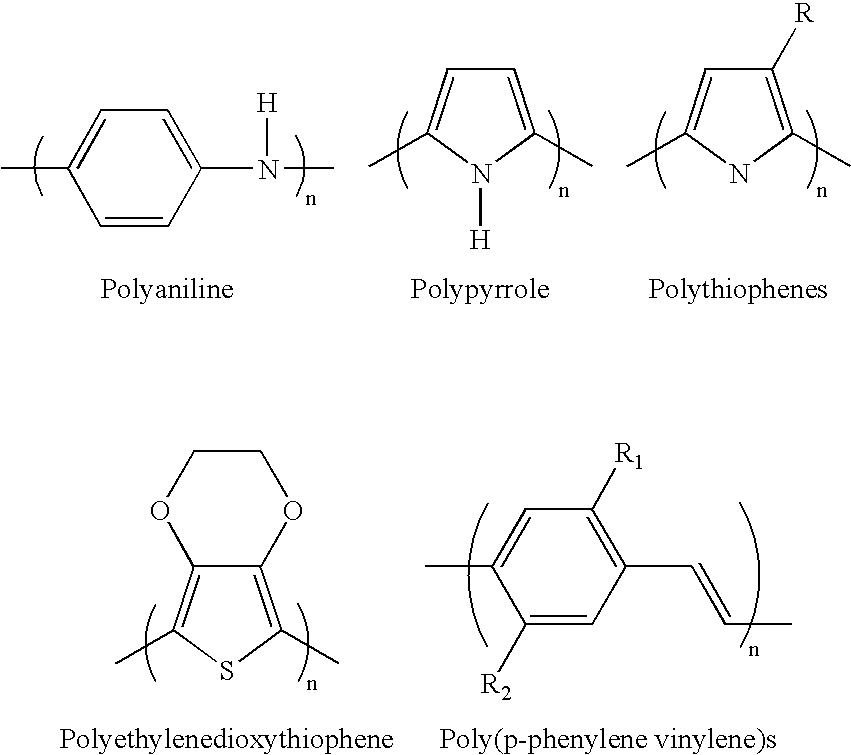
- Polypyrrole, shown in more detail below, is one of the most stable of these polymers under physiological conditions:
-

- The above list is intended for illustrative purposes only, and not as a limitation on the scope of the present invention.
- The behavior of conjugated polymers is dramatically altered with the addition of charge transfer agents (dopants). These materials can be oxidized to a p-type doped material by doping with an anionic dopant species or reducible to an n-type doped material by doping with a cationic dopant species. Generally, polymers such as polypyrrole (PPy) are partially oxidized to produce p-doped materials:
-

- Dopants have an effect on this oxidation-reduction scenario and convert semi-conducting polymers to conducting versions close to metallic conductivity in many instances. Such oxidation and reduction are believed to lead to a charge imbalance that, in turn, results in a flow of ions into or out of the material. These ions typically enter/exit the material from/into an ironically conductive electrolyte medium associated with the electroactive polymer.
- Dimensional or volumetric changes can be effectuated in certain polymers by the mass transfer of ions into or out of the polymer. This ion transfer is used to build conductive polymer actuators (volume change). For example, in some conductive polymers, expansion is believed to be due to ion insertion between chains, whereas in others inter-chain repulsion is believed to be the dominant effect. Regardless of the mechanism, the mass transfer of ions into and out of the material leads to an expansion or contraction of the polymer, delivering significant stresses (e.g., on the order of 1 MPa) and strains (e.g., on the order of 10%). These characteristics are ideal for construction of the devices of the present invention. As used herein, the expansion or the contraction of the active region of the device is generally referred to as “actuation.”
- The following elements are commonly utilized to bring about electroactive polymer actuation: (a) a source of electrical potential, (b) an active region, which comprises the electroactive polymer, (c) a counter electrode and (d) an electrolyte in contact with both the active region and the counter electrode.
- The source of electrical potential for use in connection with the present invention can be quite simple, consisting, for example, of a dc battery and an on/off switch. Alternatively, more complex systems can be utilized. For example, an electrical link can be established with a microprocessor, allowing a complex set of control signals to be sent to the EAP-containing active region(s).
- The electrolyte, which is in contact with at least a portion of the surface of the active region, allows for the flow of ions and thus acts as a source/sink for the ions. Any suitable electrolyte may be employed herein. The electrolyte may be, for example, a liquid, a gel, or a solid, so long as ion movement is permitted. Examples of suitable liquid electrolytes include, but are not limited to, an aqueous solution containing a salt, for example, a NaCl solution, a KCl solution, a sodium dodecylbenzene sulfonate solution, a phosphate buffered solution, physiological fluid, etc. Examples of suitable gel electrolytes include, but are not limited to, a salt-containing agar gel or polymethylmethacrylate (PMMA) gel. Solid electrolytes include ionic polymers different from the EAP and salt films.
- The counter electrode may be formed from any suitable electrical conductor, for example, a conducting polymer, a conducting gel, or a metal, such as stainless steel, gold or platinum. At least a portion of the surface of the counter electrode is generally in contact with the electrolyte, in order to provide a return path for charge.
- In at least one embodiment, the EAP employed is polypyrrole. Polypyrrole-containing active regions can be fabricated using a number of known techniques, for example, extrusion, casting, dip coating, spin coating, or electro-polymerization/deposition techniques. Such active regions can also be patterned, for example, using micro extrusion or lithographic techniques, if desired.
- As a specific example of a fabrication technique, polypyrrole can be galvanostatically deposited on a platinised substrate from a pyrrole monomer solution using the procedures described in D. Zhou et al., “Actuators for the Cochlear Implant,” Synthetic Metals 135-136 (2003) 39-40. Polypyrrole can also be deposited on gold. In some embodiments, adhesion of the electrodeposited polypyrrole layer is enhanced by covering a metal such as gold with a chemisorbed layer of molecules that can be copolymerized into the polymer layer with chemical bonding. Thiol is one example of a head group for strong chemisorbtion to metal. The tail group may be chemically similar to structured groups formed in the specific EAP employed. The use of a pyrrole ring attached to a thiol group (e.g., via a short alkyl chain) is an example for a polypyrrole EAP. Specific examples of such molecules are 1-(2-thioethyl)-pyrrole and 3-(2-thioethyl)-pyrrole. See, e.g., E. Smela et al., “Thiol Modified Pyrrole Monomers: 1. Synthesis, Characterization, and Polymerization of 1-(2-Thioethyl)-Pyrrole and 3-(2-Thioethyl)-Pyrrole,” Langmuir, 14 (11), 2970-2975, 1998.
- Various dopants can be used in the polypyrrole-containing active regions including large immobile anions and large immobile cations. According to at least one embodiment, the active region comprises polypyrrole (PPy) doped with dodecylbenzene sulfonate (DBS) anions. When placed in contact with an electrolyte containing small mobile cations, for example, Na+ cations, and when a current is passed between the polypyrrole-containing active region and a counter electrode, the cations are inserted/removed upon reduction/oxidation of the polymer, leading to expansion/contraction of the same. This process can be represented by the following equation:
-
PPy+(DBS−)+Na++e−⇄PPyo(Na+DBS−) - Where Na+ represents a sodium ion, e− represents an electron, PPy+ represents the oxidized state of the polypyrrole, PPyo represents the reduced state of the polymer, and species are enclosed in parentheses to indicate that they are incorporated into the polymer. In this case the sodium ions are supplied by the electrolyte that is in contact with the electroactive polymer member. Specifically, when the EAP is oxidized, the positive charges on the backbone are at least partially compensated by the DBS− anions present within the polymer. Upon reduction of the polymer, however, the immobile DBS− ions cannot exit the polymer to maintain charge neutrality, so the smaller, more mobile, Na+ ions enter the polymer, expanding the volume of the same. Upon re-oxidation, the Na+ ions again exit the polymer into the electrolyte, reducing the volume of the polymer.
- EAP-containing active regions can be provided that either expand or contract when an applied voltage of appropriate value is interrupted depending, for example, upon the selection of the EAP, dopant, and electrolyte.
- Additional information regarding EAP actuators, their design considerations, and the materials and components that may be employed therein, can be found, for example, in E. W. H. Jager, E. Smela, O. Inganäs, “Microfabricating Conjugated Polymer Actuators,” Science, 290, 1540-1545, 2000; E. Smela, M. Kallenbach, and J. Holdenried, “Electrochemically Driven Polypyrrole Bilayers for Moving and Positioning Bulk Micromachined Silicon Plates,” J. Microelectromechanical Systems, 8(4), 373-383, 1999; U.S. Pat. No. 6,249,076, assigned to Massachusetts Institute of Technology, and Proceedings of the SPIE, Vol. 4329 (2001) entitled “Smart Structures and Materials 2001: Electroactive Polymer and Actuator Devices (see, e.g., Madden et al, “Polypyrrole actuators: modeling and performance,” at pp. 72-83), each of which is hereby incorporated by reference in its entirety.
- Furthermore, networks of conductive polymers may also be employed. For example, it has been known to polymerize pyrrole in electroactive polymer networks such as poly(vinylchloride), poly(vinyl alcohol), NAFION®, a perfluorinated polymer that contains small proportions of sulfonic or carboxylic ionic functional groups., available from E.I. DuPont Co., Inc. of Wilmington, Del.
- Electroactive polymers are also discussed in detail in commonly assigned copending U.S. patent application Ser. No. 10/763,825, the entire content of which is incorporated by reference herein.
- In at least one embodiment, the medical devices of the present invention are actuated, at least in part, using materials involving piezoelectric, electrostrictive, and/or Maxwell stresses.
- The above disclosure is intended to be illustrative and not exhaustive. This description will suggest many variations and alternatives to one of ordinary skill in this art. All these alternatives and variations are intended to be included within the scope of the attached claims. Those familiar with the art may recognize other equivalents to the embodiments described herein which equivalents are also intended to be encompassed by the claims attached hereto.
Claims (20)
Priority Applications (3)
| Application Number | Priority Date | Filing Date | Title |
|---|---|---|---|
| US11/591,848 US8206429B2 (en) | 2006-11-02 | 2006-11-02 | Adjustable bifurcation catheter incorporating electroactive polymer and methods of making and using the same |
| PCT/US2007/020237 WO2008054577A1 (en) | 2006-11-02 | 2007-09-18 | Adjustable bifurcation catheter incorporating electroactive polymer and methods of making and using the same. |
| US13/530,400 US8556955B2 (en) | 2006-11-02 | 2012-06-22 | Adjustable bifurcation catheter incorporating electroactive polymer and methods of makings and using the same |
Applications Claiming Priority (1)
| Application Number | Priority Date | Filing Date | Title |
|---|---|---|---|
| US11/591,848 US8206429B2 (en) | 2006-11-02 | 2006-11-02 | Adjustable bifurcation catheter incorporating electroactive polymer and methods of making and using the same |
Related Child Applications (1)
| Application Number | Title | Priority Date | Filing Date |
|---|---|---|---|
| US13/530,400 Continuation US8556955B2 (en) | 2006-11-02 | 2012-06-22 | Adjustable bifurcation catheter incorporating electroactive polymer and methods of makings and using the same |
Publications (2)
| Publication Number | Publication Date |
|---|---|
| US20080109061A1 true US20080109061A1 (en) | 2008-05-08 |
| US8206429B2 US8206429B2 (en) | 2012-06-26 |
Family
ID=38754735
Family Applications (2)
| Application Number | Title | Priority Date | Filing Date |
|---|---|---|---|
| US11/591,848 Expired - Fee Related US8206429B2 (en) | 2006-11-02 | 2006-11-02 | Adjustable bifurcation catheter incorporating electroactive polymer and methods of making and using the same |
| US13/530,400 Expired - Fee Related US8556955B2 (en) | 2006-11-02 | 2012-06-22 | Adjustable bifurcation catheter incorporating electroactive polymer and methods of makings and using the same |
Family Applications After (1)
| Application Number | Title | Priority Date | Filing Date |
|---|---|---|---|
| US13/530,400 Expired - Fee Related US8556955B2 (en) | 2006-11-02 | 2012-06-22 | Adjustable bifurcation catheter incorporating electroactive polymer and methods of makings and using the same |
Country Status (2)
| Country | Link |
|---|---|
| US (2) | US8206429B2 (en) |
| WO (1) | WO2008054577A1 (en) |
Cited By (6)
| Publication number | Priority date | Publication date | Assignee | Title |
|---|---|---|---|---|
| US20080114434A1 (en) * | 2004-12-31 | 2008-05-15 | Boston Scientific Scimed, Inc. | Smart textile vascular graft |
| US20090306757A1 (en) * | 2008-06-10 | 2009-12-10 | Boston Scientific Scimed, Inc. | Side Branch Wiring Assist Sheath and Methods |
| US20100312322A1 (en) * | 2006-07-31 | 2010-12-09 | Boston Scientific Scimed, Inc. | Medical Balloon Incorporating Electroactive Polymer and Methods of Making and Using the Same |
| US20140276620A1 (en) * | 2013-03-14 | 2014-09-18 | Volcano Corporation | Auxiliary small vasculature guidewire |
| US20180272111A1 (en) * | 2013-03-14 | 2018-09-27 | Volcano Corporation | Auxiliary small vasculature guidewire |
| US10470871B2 (en) | 2001-12-20 | 2019-11-12 | Trivascular, Inc. | Advanced endovascular graft |
Families Citing this family (55)
| Publication number | Priority date | Publication date | Assignee | Title |
|---|---|---|---|---|
| US7850645B2 (en) * | 2005-02-11 | 2010-12-14 | Boston Scientific Scimed, Inc. | Internal medical devices for delivery of therapeutic agent in conjunction with a source of electrical power |
| US9867530B2 (en) | 2006-08-14 | 2018-01-16 | Volcano Corporation | Telescopic side port catheter device with imaging system and method for accessing side branch occlusions |
| WO2009009799A1 (en) | 2007-07-12 | 2009-01-15 | Volcano Corporation | Catheter for in vivo imaging |
| US9596993B2 (en) | 2007-07-12 | 2017-03-21 | Volcano Corporation | Automatic calibration systems and methods of use |
| WO2009009802A1 (en) | 2007-07-12 | 2009-01-15 | Volcano Corporation | Oct-ivus catheter for concurrent luminal imaging |
| US20090287148A1 (en) * | 2008-05-15 | 2009-11-19 | Martin Daryl L | Joined Inflation Portions for Bifurcation Catheter |
| EP2344068B1 (en) | 2008-09-25 | 2022-10-19 | Advanced Bifurcation Systems Inc. | Partially crimped stent |
| US11298252B2 (en) | 2008-09-25 | 2022-04-12 | Advanced Bifurcation Systems Inc. | Stent alignment during treatment of a bifurcation |
| US8769796B2 (en) | 2008-09-25 | 2014-07-08 | Advanced Bifurcation Systems, Inc. | Selective stent crimping |
| CA2794080A1 (en) | 2010-03-24 | 2011-09-29 | Advanced Bifurcation Systems, Inc. | System and methods for treating a bifurcation |
| US11141063B2 (en) | 2010-12-23 | 2021-10-12 | Philips Image Guided Therapy Corporation | Integrated system architectures and methods of use |
| US11040140B2 (en) | 2010-12-31 | 2021-06-22 | Philips Image Guided Therapy Corporation | Deep vein thrombosis therapeutic methods |
| US20120179097A1 (en) | 2011-01-06 | 2012-07-12 | Cully Edward H | Methods and apparatus for an adjustable stiffness catheter |
| US9360630B2 (en) | 2011-08-31 | 2016-06-07 | Volcano Corporation | Optical-electrical rotary joint and methods of use |
| US9147825B2 (en) | 2012-03-07 | 2015-09-29 | Board of Regents of the Nevada System of Higher Education on behalf of the University of Nevado, Reno | Methods of fabricating multi-degree of freedom shaped electroactive polymer actuators/sensors for catheters |
| US9292918B2 (en) | 2012-10-05 | 2016-03-22 | Volcano Corporation | Methods and systems for transforming luminal images |
| US10070827B2 (en) | 2012-10-05 | 2018-09-11 | Volcano Corporation | Automatic image playback |
| US9858668B2 (en) | 2012-10-05 | 2018-01-02 | Volcano Corporation | Guidewire artifact removal in images |
| US9324141B2 (en) | 2012-10-05 | 2016-04-26 | Volcano Corporation | Removal of A-scan streaking artifact |
| US9307926B2 (en) | 2012-10-05 | 2016-04-12 | Volcano Corporation | Automatic stent detection |
| US9367965B2 (en) | 2012-10-05 | 2016-06-14 | Volcano Corporation | Systems and methods for generating images of tissue |
| US9286673B2 (en) | 2012-10-05 | 2016-03-15 | Volcano Corporation | Systems for correcting distortions in a medical image and methods of use thereof |
| US11272845B2 (en) | 2012-10-05 | 2022-03-15 | Philips Image Guided Therapy Corporation | System and method for instant and automatic border detection |
| JP2015532536A (en) | 2012-10-05 | 2015-11-09 | デイビッド ウェルフォード, | System and method for amplifying light |
| US10568586B2 (en) | 2012-10-05 | 2020-02-25 | Volcano Corporation | Systems for indicating parameters in an imaging data set and methods of use |
| US9840734B2 (en) | 2012-10-22 | 2017-12-12 | Raindance Technologies, Inc. | Methods for analyzing DNA |
| EP2931132B1 (en) | 2012-12-13 | 2023-07-05 | Philips Image Guided Therapy Corporation | System for targeted cannulation |
| CA2895770A1 (en) | 2012-12-20 | 2014-07-24 | Jeremy Stigall | Locating intravascular images |
| US10939826B2 (en) | 2012-12-20 | 2021-03-09 | Philips Image Guided Therapy Corporation | Aspirating and removing biological material |
| EP2934310A4 (en) | 2012-12-20 | 2016-10-12 | Nathaniel J Kemp | Optical coherence tomography system that is reconfigurable between different imaging modes |
| US10942022B2 (en) | 2012-12-20 | 2021-03-09 | Philips Image Guided Therapy Corporation | Manual calibration of imaging system |
| US11406498B2 (en) | 2012-12-20 | 2022-08-09 | Philips Image Guided Therapy Corporation | Implant delivery system and implants |
| WO2014099899A1 (en) | 2012-12-20 | 2014-06-26 | Jeremy Stigall | Smooth transition catheters |
| EP2934323A4 (en) | 2012-12-21 | 2016-08-17 | Andrew Hancock | System and method for multipath processing of image signals |
| US9486143B2 (en) | 2012-12-21 | 2016-11-08 | Volcano Corporation | Intravascular forward imaging device |
| CA2896006A1 (en) | 2012-12-21 | 2014-06-26 | David Welford | Systems and methods for narrowing a wavelength emission of light |
| EP2936426B1 (en) | 2012-12-21 | 2021-10-13 | Jason Spencer | System and method for graphical processing of medical data |
| EP2934280B1 (en) | 2012-12-21 | 2022-10-19 | Mai, Jerome | Ultrasound imaging with variable line density |
| WO2014100162A1 (en) | 2012-12-21 | 2014-06-26 | Kemp Nathaniel J | Power-efficient optical buffering using optical switch |
| US10058284B2 (en) | 2012-12-21 | 2018-08-28 | Volcano Corporation | Simultaneous imaging, monitoring, and therapy |
| WO2014100606A1 (en) | 2012-12-21 | 2014-06-26 | Meyer, Douglas | Rotational ultrasound imaging catheter with extended catheter body telescope |
| US10413317B2 (en) | 2012-12-21 | 2019-09-17 | Volcano Corporation | System and method for catheter steering and operation |
| US9612105B2 (en) | 2012-12-21 | 2017-04-04 | Volcano Corporation | Polarization sensitive optical coherence tomography system |
| US9770172B2 (en) | 2013-03-07 | 2017-09-26 | Volcano Corporation | Multimodal segmentation in intravascular images |
| US10226597B2 (en) | 2013-03-07 | 2019-03-12 | Volcano Corporation | Guidewire with centering mechanism |
| US11154313B2 (en) | 2013-03-12 | 2021-10-26 | The Volcano Corporation | Vibrating guidewire torquer and methods of use |
| EP2967391A4 (en) | 2013-03-12 | 2016-11-02 | Donna Collins | Systems and methods for diagnosing coronary microvascular disease |
| US9301687B2 (en) | 2013-03-13 | 2016-04-05 | Volcano Corporation | System and method for OCT depth calibration |
| US10758207B2 (en) | 2013-03-13 | 2020-09-01 | Philips Image Guided Therapy Corporation | Systems and methods for producing an image from a rotational intravascular ultrasound device |
| US11026591B2 (en) | 2013-03-13 | 2021-06-08 | Philips Image Guided Therapy Corporation | Intravascular pressure sensor calibration |
| US20160030151A1 (en) | 2013-03-14 | 2016-02-04 | Volcano Corporation | Filters with echogenic characteristics |
| US10292677B2 (en) | 2013-03-14 | 2019-05-21 | Volcano Corporation | Endoluminal filter having enhanced echogenic properties |
| US10219887B2 (en) | 2013-03-14 | 2019-03-05 | Volcano Corporation | Filters with echogenic characteristics |
| CA3185892A1 (en) | 2016-02-05 | 2017-08-10 | Board Of Regents Of The University Of Texas System | Surgical apparatus |
| AU2017214568B9 (en) | 2016-02-05 | 2020-07-09 | Board Of Regents Of The University Of Texas System | Steerable intra-luminal medical device |
Citations (28)
| Publication number | Priority date | Publication date | Assignee | Title |
|---|---|---|---|---|
| US5396879A (en) * | 1992-04-09 | 1995-03-14 | Wilk; Peter J. | Elongate medical instrument with distal end orientation control |
| US5573520A (en) * | 1991-09-05 | 1996-11-12 | Mayo Foundation For Medical Education And Research | Flexible tubular device for use in medical applications |
| US5800421A (en) * | 1996-06-12 | 1998-09-01 | Lemelson; Jerome H. | Medical devices using electrosensitive gels |
| US5855565A (en) * | 1997-02-21 | 1999-01-05 | Bar-Cohen; Yaniv | Cardiovascular mechanically expanding catheter |
| US6117296A (en) * | 1998-07-21 | 2000-09-12 | Thomson; Timothy | Electrically controlled contractile polymer composite |
| US6249076B1 (en) * | 1998-04-14 | 2001-06-19 | Massachusetts Institute Of Technology | Conducting polymer actuator |
| US6379393B1 (en) * | 1998-09-14 | 2002-04-30 | Rutgers, The State University Of New Jersey | Prosthetic, orthotic, and other rehabilitative robotic assistive devices actuated by smart materials |
| US20020054060A1 (en) * | 2000-05-24 | 2002-05-09 | Schena Bruce M. | Haptic devices using electroactive polymers |
| US6388043B1 (en) * | 1998-02-23 | 2002-05-14 | Mnemoscience Gmbh | Shape memory polymers |
| US20020193735A1 (en) * | 2001-06-19 | 2002-12-19 | Medtronic Ave, Inc. | Intraluminal therapy catheter with inflatable helical member and methods of use |
| US6514237B1 (en) * | 2000-11-06 | 2003-02-04 | Cordis Corporation | Controllable intralumen medical device |
| US20030065373A1 (en) * | 2001-10-02 | 2003-04-03 | Lovett Eric G. | Medical device having rheometric materials and method therefor |
| US20030068522A1 (en) * | 2001-05-31 | 2003-04-10 | Cheng-Chi Wang | Hillock-free aluminum wiring layer and method of forming the same |
| US20030236445A1 (en) * | 2002-06-21 | 2003-12-25 | Couvillon Lucien Alfred | Universal programmable guide catheter |
| US20040068161A1 (en) * | 2002-10-02 | 2004-04-08 | Couvillon Lucien Alfred | Thrombolysis catheter |
| US20040087982A1 (en) * | 2002-08-07 | 2004-05-06 | Eskuri Alan David | Electroactive polymer actuated medical devices |
| US6749556B2 (en) * | 2002-05-10 | 2004-06-15 | Scimed Life Systems, Inc. | Electroactive polymer based artificial sphincters and artificial muscle patches |
| US6770027B2 (en) * | 2001-10-05 | 2004-08-03 | Scimed Life Systems, Inc. | Robotic endoscope with wireless interface |
| US6812624B1 (en) * | 1999-07-20 | 2004-11-02 | Sri International | Electroactive polymers |
| US6835173B2 (en) * | 2001-10-05 | 2004-12-28 | Scimed Life Systems, Inc. | Robotic endoscope |
| US6882086B2 (en) * | 2001-05-22 | 2005-04-19 | Sri International | Variable stiffness electroactive polymer systems |
| US20050085693A1 (en) * | 2000-04-03 | 2005-04-21 | Amir Belson | Activated polymer articulated instruments and methods of insertion |
| US20050102017A1 (en) * | 2003-11-06 | 2005-05-12 | Mattison Richard C. | Electroactive polymer actuated sheath for implantable or insertable medical device |
| US20050165439A1 (en) * | 2004-01-23 | 2005-07-28 | Jan Weber | Electrically actuated medical devices |
| US20050187602A1 (en) * | 2004-02-24 | 2005-08-25 | Tracee Eidenschink | Rotatable catheter assembly |
| US20050183259A1 (en) * | 2004-02-23 | 2005-08-25 | Tracee Eidenschink | Apparatus and method for crimping a stent assembly |
| US7063671B2 (en) * | 2002-06-21 | 2006-06-20 | Boston Scientific Scimed, Inc. | Electronically activated capture device |
| US20060206188A1 (en) * | 2005-03-14 | 2006-09-14 | Jan Weber | Bifurcation delivery system |
Family Cites Families (178)
| Publication number | Priority date | Publication date | Assignee | Title |
|---|---|---|---|---|
| US4309994A (en) | 1980-02-25 | 1982-01-12 | Grunwald Ronald P | Cardiovascular cannula |
| US4774949A (en) | 1983-06-14 | 1988-10-04 | Fogarty Thomas J | Deflector guiding catheter |
| DE8717643U1 (en) | 1987-05-12 | 1989-09-21 | Foerster, Ernst, Dr.Med. Dr.Rer.Nat. | |
| US4769005A (en) | 1987-08-06 | 1988-09-06 | Robert Ginsburg | Selective catheter guide |
| US4896670A (en) | 1988-04-19 | 1990-01-30 | C. R. Bard, Inc. | Kissing balloon catheter |
| US4994071A (en) | 1989-05-22 | 1991-02-19 | Cordis Corporation | Bifurcating stent apparatus and method |
| US5147385A (en) | 1989-11-01 | 1992-09-15 | Schneider (Europe) A.G. | Stent and catheter for the introduction of the stent |
| AR246020A1 (en) | 1990-10-03 | 1994-03-30 | Hector Daniel Barone Juan Carl | A ball device for implanting an intraluminous aortic prosthesis, for repairing aneurysms. |
| EP0479730B1 (en) | 1990-10-04 | 1995-04-19 | Schneider (Europe) Ag | Balloon dilatation catheter |
| US5628783A (en) | 1991-04-11 | 1997-05-13 | Endovascular Technologies, Inc. | Bifurcated multicapsule intraluminal grafting system and method |
| US5304220A (en) | 1991-07-03 | 1994-04-19 | Maginot Thomas J | Method and apparatus for implanting a graft prosthesis in the body of a patient |
| FR2678508B1 (en) | 1991-07-04 | 1998-01-30 | Celsa Lg | DEVICE FOR REINFORCING VESSELS OF THE HUMAN BODY. |
| US5693084A (en) | 1991-10-25 | 1997-12-02 | Cook Incorporated | Expandable transluminal graft prosthesis for repair of aneurysm |
| US5387235A (en) | 1991-10-25 | 1995-02-07 | Cook Incorporated | Expandable transluminal graft prosthesis for repair of aneurysm |
| US5342387A (en) | 1992-06-18 | 1994-08-30 | American Biomed, Inc. | Artificial support for a blood vessel |
| US5487730A (en) | 1992-12-30 | 1996-01-30 | Medtronic, Inc. | Balloon catheter with balloon surface retention means |
| IL106738A (en) | 1993-08-19 | 1998-02-08 | Mind E M S G Ltd | Device for external correction of deficient valves in venous junctions |
| US5632772A (en) | 1993-10-21 | 1997-05-27 | Corvita Corporation | Expandable supportive branched endoluminal grafts |
| US5639278A (en) | 1993-10-21 | 1997-06-17 | Corvita Corporation | Expandable supportive bifurcated endoluminal grafts |
| US5607444A (en) | 1993-12-02 | 1997-03-04 | Advanced Cardiovascular Systems, Inc. | Ostial stent for bifurcations |
| US5609627A (en) | 1994-02-09 | 1997-03-11 | Boston Scientific Technology, Inc. | Method for delivering a bifurcated endoluminal prosthesis |
| US5683451A (en) | 1994-06-08 | 1997-11-04 | Cardiovascular Concepts, Inc. | Apparatus and methods for deployment release of intraluminal prostheses |
| US5636641A (en) | 1994-07-25 | 1997-06-10 | Advanced Cardiovascular Systems, Inc. | High strength member for intracorporeal use |
| US5609605A (en) | 1994-08-25 | 1997-03-11 | Ethicon, Inc. | Combination arterial stent |
| CA2134997C (en) | 1994-11-03 | 2009-06-02 | Ian M. Penn | Stent |
| CA2175720C (en) | 1996-05-03 | 2011-11-29 | Ian M. Penn | Bifurcated stent and method for the manufacture and delivery of same |
| US5613980A (en) | 1994-12-22 | 1997-03-25 | Chauhan; Tusharsindhu C. | Bifurcated catheter system and method |
| NL9500094A (en) | 1995-01-19 | 1996-09-02 | Industrial Res Bv | Y-shaped stent and method of deployment. |
| US7204848B1 (en) | 1995-03-01 | 2007-04-17 | Boston Scientific Scimed, Inc. | Longitudinally flexible expandable stent |
| US5709713A (en) | 1995-03-31 | 1998-01-20 | Cardiovascular Concepts, Inc. | Radially expansible vascular prosthesis having reversible and other locking structures |
| FR2733682B1 (en) | 1995-05-04 | 1997-10-31 | Dibie Alain | ENDOPROSTHESIS FOR THE TREATMENT OF STENOSIS ON BIFURCATIONS OF BLOOD VESSELS AND LAYING EQUIPMENT THEREFOR |
| US5591228A (en) | 1995-05-09 | 1997-01-07 | Edoga; John K. | Methods for treating abdominal aortic aneurysms |
| US5707348A (en) | 1995-06-06 | 1998-01-13 | Krogh; Steve S. | Intravenous bandage |
| EP0830108B1 (en) | 1995-06-08 | 2003-09-17 | Ave Galway Limited | Endovascular stent |
| FR2737969B1 (en) | 1995-08-24 | 1998-01-30 | Rieu Regis | INTRALUMINAL ENDOPROSTHESIS IN PARTICULAR FOR ANGIOPLASTY |
| US5824036A (en) | 1995-09-29 | 1998-10-20 | Datascope Corp | Stent for intraluminal grafts and device and methods for delivering and assembling same |
| US5669924A (en) | 1995-10-26 | 1997-09-23 | Shaknovich; Alexander | Y-shuttle stent assembly for bifurcating vessels and method of using the same |
| FR2740346A1 (en) | 1995-10-30 | 1997-04-30 | Debiotech Sa | ANGIOPLASTY DEVICE FOR ARTERIAL BIFURCATION |
| US5632762A (en) | 1995-11-09 | 1997-05-27 | Hemodynamics, Inc. | Ostial stent balloon |
| US5824040A (en) | 1995-12-01 | 1998-10-20 | Medtronic, Inc. | Endoluminal prostheses and therapies for highly variable body lumens |
| US6436104B2 (en) | 1996-01-26 | 2002-08-20 | Cordis Corporation | Bifurcated axially flexible stent |
| US6017363A (en) | 1997-09-22 | 2000-01-25 | Cordis Corporation | Bifurcated axially flexible stent |
| US6258116B1 (en) | 1996-01-26 | 2001-07-10 | Cordis Corporation | Bifurcated axially flexible stent |
| US5824042A (en) | 1996-04-05 | 1998-10-20 | Medtronic, Inc. | Endoluminal prostheses having position indicating markers |
| BE1010183A3 (en) | 1996-04-25 | 1998-02-03 | Dereume Jean Pierre Georges Em | Luminal endoprosthesis FOR BRANCHING CHANNELS OF A HUMAN OR ANIMAL BODY AND MANUFACTURING METHOD THEREOF. |
| US6251133B1 (en) | 1996-05-03 | 2001-06-26 | Medinol Ltd. | Bifurcated stent with improved side branch aperture and method of making same |
| UA58485C2 (en) | 1996-05-03 | 2003-08-15 | Медінол Лтд. | Method for manufacture of bifurcated stent (variants) and bifurcated stent (variants) |
| US6440165B1 (en) | 1996-05-03 | 2002-08-27 | Medinol, Ltd. | Bifurcated stent with improved side branch aperture and method of making same |
| US6770092B2 (en) | 1996-05-03 | 2004-08-03 | Medinol Ltd. | Method of delivering a bifurcated stent |
| US5851464A (en) | 1996-05-13 | 1998-12-22 | Cordis Corporation | Method of making a fuseless soft tip catheter |
| US5669932A (en) | 1996-05-29 | 1997-09-23 | Isostent, Inc. | Means for accurately positioning an expandable stent |
| US5617878A (en) | 1996-05-31 | 1997-04-08 | Taheri; Syde A. | Stent and method for treatment of aortic occlusive disease |
| IL122904A0 (en) | 1996-05-31 | 1998-08-16 | Bard Galway Ltd | Bifurcated endovascular stents and method and apparatus for their placement |
| US5755773A (en) | 1996-06-04 | 1998-05-26 | Medtronic, Inc. | Endoluminal prosthetic bifurcation shunt |
| FR2749500B1 (en) | 1996-06-06 | 1998-11-20 | Jacques Seguin | DEVICE ALLOWING THE TREATMENT OF BODY DUCTS AT THE LEVEL OF A BIFURCATION |
| US7238197B2 (en) | 2000-05-30 | 2007-07-03 | Devax, Inc. | Endoprosthesis deployment system for treating vascular bifurcations |
| US8728143B2 (en) | 1996-06-06 | 2014-05-20 | Biosensors International Group, Ltd. | Endoprosthesis deployment system for treating vascular bifurcations |
| US5697971A (en) | 1996-06-11 | 1997-12-16 | Fischell; Robert E. | Multi-cell stent with cells having differing characteristics |
| US5676697A (en) | 1996-07-29 | 1997-10-14 | Cardiovascular Dynamics, Inc. | Two-piece, bifurcated intraluminal graft for repair of aneurysm |
| US5749825A (en) | 1996-09-18 | 1998-05-12 | Isostent, Inc. | Means method for treatment of stenosed arterial bifurcations |
| US5755778A (en) | 1996-10-16 | 1998-05-26 | Nitinol Medical Technologies, Inc. | Anastomosis device |
| ATE539702T1 (en) | 1996-11-04 | 2012-01-15 | Advanced Stent Tech Inc | DEVICE FOR EXPANDING A STENT AND METHOD FOR DEPLOYING IT |
| US6596020B2 (en) | 1996-11-04 | 2003-07-22 | Advanced Stent Technologies, Inc. | Method of delivering a stent with a side opening |
| US7591846B2 (en) | 1996-11-04 | 2009-09-22 | Boston Scientific Scimed, Inc. | Methods for deploying stents in bifurcations |
| US6692483B2 (en) | 1996-11-04 | 2004-02-17 | Advanced Stent Technologies, Inc. | Catheter with attached flexible side sheath |
| US6599316B2 (en) | 1996-11-04 | 2003-07-29 | Advanced Stent Technologies, Inc. | Extendible stent apparatus |
| US6835203B1 (en) | 1996-11-04 | 2004-12-28 | Advanced Stent Technologies, Inc. | Extendible stent apparatus |
| US7341598B2 (en) | 1999-01-13 | 2008-03-11 | Boston Scientific Scimed, Inc. | Stent with protruding branch portion for bifurcated vessels |
| US6325826B1 (en) | 1998-01-14 | 2001-12-04 | Advanced Stent Technologies, Inc. | Extendible stent apparatus |
| US5972017A (en) | 1997-04-23 | 1999-10-26 | Vascular Science Inc. | Method of installing tubular medical graft connectors |
| FR2756173B1 (en) | 1996-11-22 | 1999-02-12 | Marcade Jean Paul | MODULAR AND EXPANDABLE ENDOPROSTHESIS FOR THE ARTERIAL NETWORK |
| US5749890A (en) | 1996-12-03 | 1998-05-12 | Shaknovich; Alexander | Method and system for stent placement in ostial lesions |
| DE29701758U1 (en) | 1997-02-01 | 1997-03-27 | Jomed Implantate Gmbh | Radially expandable stent for implantation in a body vessel, particularly in the area of a vascular branch |
| DE29701883U1 (en) | 1997-02-04 | 1997-03-27 | Beck Harry | Central lubrication |
| US6781284B1 (en) | 1997-02-07 | 2004-08-24 | Sri International | Electroactive polymer transducers and actuators |
| US5720735A (en) | 1997-02-12 | 1998-02-24 | Dorros; Gerald | Bifurcated endovascular catheter |
| US6096073A (en) | 1997-02-25 | 2000-08-01 | Scimed Life Systems, Inc. | Method of deploying a stent at a lesion site located at a bifurcation in a parent vessel |
| US20020133222A1 (en) | 1997-03-05 | 2002-09-19 | Das Gladwin S. | Expandable stent having a plurality of interconnected expansion modules |
| US6258115B1 (en) | 1997-04-23 | 2001-07-10 | Artemis Medical, Inc. | Bifurcated stent and distal protection system |
| US6013054A (en) | 1997-04-28 | 2000-01-11 | Advanced Cardiovascular Systems, Inc. | Multifurcated balloon catheter |
| DE69835634T3 (en) | 1997-05-07 | 2010-09-23 | Cordis Corp. | Intravascular stent and insertion system (obstruction of the ostium of a vessel) |
| DE29708803U1 (en) | 1997-05-17 | 1997-07-31 | Jomed Implantate Gmbh | Radially expandable stent for implantation in a body vessel in the area of a vascular branch |
| US5906641A (en) | 1997-05-27 | 1999-05-25 | Schneider (Usa) Inc | Bifurcated stent graft |
| CA2424551A1 (en) | 1997-05-27 | 1998-11-27 | Schneider (Usa) Inc. | Stent and stent-graft for treating branched vessels |
| EP0891751A1 (en) | 1997-07-18 | 1999-01-20 | Thomas Prof. Dr. Ischinger | Vascular stent for bifurcations, sidebranches and ostial lesions and an application catheter and method for implantation |
| IT1293690B1 (en) | 1997-08-08 | 1999-03-08 | Sorin Biomedica Cardio Spa | ANGIOPLASTIC STENT, PARTICULARLY FOR THE TREATMENT OF AORTO-HOSPITAL AND HOSPITAL INJURIES. |
| US6165195A (en) | 1997-08-13 | 2000-12-26 | Advanced Cardiovascylar Systems, Inc. | Stent and catheter assembly and method for treating bifurcations |
| US6361544B1 (en) | 1997-08-13 | 2002-03-26 | Advanced Cardiovascular Systems, Inc. | Stent and catheter assembly and method for treating bifurcations |
| US6520988B1 (en) | 1997-09-24 | 2003-02-18 | Medtronic Ave, Inc. | Endolumenal prosthesis and method of use in bifurcation regions of body lumens |
| US6086611A (en) | 1997-09-25 | 2000-07-11 | Ave Connaught | Bifurcated stent |
| US5893887A (en) | 1997-10-14 | 1999-04-13 | Iowa-India Investments Company Limited | Stent for positioning at junction of bifurcated blood vessel and method of making |
| US6033435A (en) | 1997-11-03 | 2000-03-07 | Divysio Solutions Ulc | Bifurcated stent and method for the manufacture and delivery of same |
| AU1170199A (en) | 1997-11-07 | 1999-05-31 | Ave Connaught | Balloon catheter for repairing bifurcated vessels |
| US6030414A (en) | 1997-11-13 | 2000-02-29 | Taheri; Syde A. | Variable stent and method for treatment of arterial disease |
| US5961548A (en) | 1997-11-18 | 1999-10-05 | Shmulewitz; Ascher | Bifurcated two-part graft and methods of implantation |
| CA2220864A1 (en) | 1998-01-20 | 1999-07-20 | Nisar Huq | A bifurcation stent |
| US6395018B1 (en) | 1998-02-09 | 2002-05-28 | Wilfrido R. Castaneda | Endovascular graft and process for bridging a defect in a main vessel near one of more branch vessels |
| AU754966B2 (en) | 1998-02-12 | 2002-11-28 | Thomas R. Marotta | Endovascular prosthesis |
| US6113579A (en) | 1998-03-04 | 2000-09-05 | Scimed Life Systems, Inc. | Catheter tip designs and methods for improved stent crossing |
| US5938697A (en) | 1998-03-04 | 1999-08-17 | Scimed Life Systems, Inc. | Stent having variable properties |
| US6099497A (en) | 1998-03-05 | 2000-08-08 | Scimed Life Systems, Inc. | Dilatation and stent delivery system for bifurcation lesions |
| US6093203A (en) | 1998-05-13 | 2000-07-25 | Uflacker; Renan | Stent or graft support structure for treating bifurcated vessels having different diameter portions and methods of use and implantation |
| US6168621B1 (en) | 1998-05-29 | 2001-01-02 | Scimed Life Systems, Inc. | Balloon expandable stent with a self-expanding portion |
| US6129738A (en) | 1998-06-20 | 2000-10-10 | Medtronic Ave, Inc. | Method and apparatus for treating stenoses at bifurcated regions |
| US6264662B1 (en) | 1998-07-21 | 2001-07-24 | Sulzer Vascutek Ltd. | Insertion aid for a bifurcated prosthesis |
| US6143002A (en) | 1998-08-04 | 2000-11-07 | Scimed Life Systems, Inc. | System for delivering stents to bifurcation lesions |
| US6117117A (en) | 1998-08-24 | 2000-09-12 | Advanced Cardiovascular Systems, Inc. | Bifurcated catheter assembly |
| US6017324A (en) | 1998-10-20 | 2000-01-25 | Tu; Lily Chen | Dilatation catheter having a bifurcated balloon |
| US6293967B1 (en) | 1998-10-29 | 2001-09-25 | Conor Medsystems, Inc. | Expandable medical device with ductile hinges |
| AU1474700A (en) | 1998-12-11 | 2000-06-26 | Endologix, Inc. | Endoluminal vascular prosthesis |
| US6059824A (en) | 1998-12-23 | 2000-05-09 | Taheri; Syde A. | Mated main and collateral stent and method for treatment of arterial disease |
| US7655030B2 (en) | 2003-07-18 | 2010-02-02 | Boston Scientific Scimed, Inc. | Catheter balloon systems and methods |
| US20050060027A1 (en) | 1999-01-13 | 2005-03-17 | Advanced Stent Technologies, Inc. | Catheter balloon systems and methods |
| CA2360587A1 (en) | 1999-01-15 | 2000-07-20 | Darin C. Gittings | Methods and devices for forming vascular anastomoses |
| IT1309583B1 (en) | 1999-02-26 | 2002-01-24 | Ams Italia S R L | PERFECTED CATHETER FOR VASCULAR INTERVENTIONS. |
| US6261316B1 (en) | 1999-03-11 | 2001-07-17 | Endologix, Inc. | Single puncture bifurcation graft deployment system |
| US6258099B1 (en) | 1999-03-31 | 2001-07-10 | Scimed Life Systems, Inc. | Stent security balloon/balloon catheter |
| US6290673B1 (en) | 1999-05-20 | 2001-09-18 | Conor Medsystems, Inc. | Expandable medical device delivery system and method |
| US7387639B2 (en) | 1999-06-04 | 2008-06-17 | Advanced Stent Technologies, Inc. | Short sleeve stent delivery catheter and methods |
| US6884258B2 (en) | 1999-06-04 | 2005-04-26 | Advanced Stent Technologies, Inc. | Bifurcation lesion stent delivery using multiple guidewires |
| DE19934923A1 (en) | 1999-07-20 | 2001-01-25 | Biotronik Mess & Therapieg | Balloon catheter |
| DE19938377A1 (en) | 1999-08-06 | 2001-03-01 | Biotronik Mess & Therapieg | Stent for vascular branching |
| US6293968B1 (en) | 1999-09-02 | 2001-09-25 | Syde A. Taheri | Inflatable intraluminal vascular stent |
| US6689156B1 (en) | 1999-09-23 | 2004-02-10 | Advanced Stent Technologies, Inc. | Stent range transducers and methods of use |
| EP1229859A2 (en) | 1999-09-23 | 2002-08-14 | Advanced Stent Technologies, Inc. | Bifurcation stent system and method |
| US6383213B2 (en) | 1999-10-05 | 2002-05-07 | Advanced Cardiovascular Systems, Inc. | Stent and catheter assembly and method for treating bifurcations |
| US6387120B2 (en) | 1999-12-09 | 2002-05-14 | Advanced Cardiovascular Systems, Inc. | Stent and catheter assembly and method for treating bifurcations |
| US6254593B1 (en) | 1999-12-10 | 2001-07-03 | Advanced Cardiovascular Systems, Inc. | Bifurcated stent delivery system having retractable sheath |
| US6361555B1 (en) | 1999-12-15 | 2002-03-26 | Advanced Cardiovascular Systems, Inc. | Stent and stent delivery assembly and method of use |
| US6325822B1 (en) | 2000-01-31 | 2001-12-04 | Scimed Life Systems, Inc. | Braided stent having tapered filaments |
| PT1259192E (en) | 2000-03-03 | 2004-04-30 | Cook Inc | ENDOVASCULAR DEVICE WITH A ENDOPROTESE |
| US6210433B1 (en) | 2000-03-17 | 2001-04-03 | LARRé JORGE CASADO | Stent for treatment of lesions of bifurcated vessels |
| US6468301B1 (en) | 2000-03-27 | 2002-10-22 | Aga Medical Corporation | Repositionable and recapturable vascular stent/graft |
| US6334864B1 (en) | 2000-05-17 | 2002-01-01 | Aga Medical Corp. | Alignment member for delivering a non-symmetric device with a predefined orientation |
| US6982514B1 (en) | 2000-05-22 | 2006-01-03 | Santa Fe Science And Technology, Inc. | Electrochemical devices incorporating high-conductivity conjugated polymers |
| US7101391B2 (en) | 2000-09-18 | 2006-09-05 | Inflow Dynamics Inc. | Primarily niobium stent |
| US20020072792A1 (en) | 2000-09-22 | 2002-06-13 | Robert Burgermeister | Stent with optimal strength and radiopacity characteristics |
| AU2001296716A1 (en) | 2000-10-13 | 2002-04-22 | Rex Medical, Lp | Covered stents with side branch |
| US6582394B1 (en) | 2000-11-14 | 2003-06-24 | Advanced Cardiovascular Systems, Inc. | Stent and catheter assembly and method for treating bifurcated vessels |
| US6645242B1 (en) | 2000-12-11 | 2003-11-11 | Stephen F. Quinn | Bifurcated side-access intravascular stent graft |
| AU2003279704A1 (en) | 2000-12-27 | 2004-04-08 | Advanced Stent Technologies, Inc. | Stent with protruding branch portion for bifurcated vessels |
| US6695877B2 (en) | 2001-02-26 | 2004-02-24 | Scimed Life Systems | Bifurcated stent |
| AU2002250189A1 (en) | 2001-02-26 | 2002-09-12 | Scimed Life Systems, Inc. | Bifurcated stent and delivery system |
| US7799064B2 (en) | 2001-02-26 | 2010-09-21 | Boston Scientific Scimed, Inc. | Bifurcated stent and delivery system |
| FR2822370B1 (en) | 2001-03-23 | 2004-03-05 | Perouse Lab | TUBULAR ENDOPROSTHESIS COMPRISING A DEFORMABLE RING AND REQUIRED OF INTERVENTION FOR ITS IMPLANTATION |
| US6749628B1 (en) | 2001-05-17 | 2004-06-15 | Advanced Cardiovascular Systems, Inc. | Stent and catheter assembly and method for treating bifurcations |
| US8337540B2 (en) | 2001-05-17 | 2012-12-25 | Advanced Cardiovascular Systems, Inc. | Stent for treating bifurcations and method of use |
| WO2002102277A2 (en) | 2001-06-18 | 2002-12-27 | Eva Corporation | Prosthetic graft assembly and method of use |
| US6743259B2 (en) | 2001-08-03 | 2004-06-01 | Core Medical, Inc. | Lung assist apparatus and methods for use |
| JP4460289B2 (en) | 2001-08-23 | 2010-05-12 | シー. ガム、ダレル | Catheter assembly |
| US7252679B2 (en) | 2001-09-13 | 2007-08-07 | Cordis Corporation | Stent with angulated struts |
| US7004963B2 (en) | 2001-09-14 | 2006-02-28 | Scimed Life Systems, Inc. | Conformable balloons |
| US6939368B2 (en) | 2002-01-17 | 2005-09-06 | Scimed Life Systems, Inc. | Delivery system for self expanding stents for use in bifurcated vessels |
| AU2003234651B2 (en) | 2002-05-28 | 2005-10-06 | The Cleveland Clinic Foundation | Minimally invasive treatment system for aortic aneurysms |
| US6858038B2 (en) | 2002-06-21 | 2005-02-22 | Richard R. Heuser | Stent system |
| US6761734B2 (en) | 2002-07-22 | 2004-07-13 | William S. Suhr | Segmented balloon catheter for stenting bifurcation lesions |
| US20040059406A1 (en) | 2002-09-20 | 2004-03-25 | Cully Edward H. | Medical device amenable to fenestration |
| AU2003276920A1 (en) | 2002-09-20 | 2004-04-08 | Innovational Holdings, Llc | Expandable medical device with openings for delivery of multiple beneficial agents |
| US7326242B2 (en) | 2002-11-05 | 2008-02-05 | Boston Scientific Scimed, Inc. | Asymmetric bifurcated crown |
| US7314480B2 (en) | 2003-02-27 | 2008-01-01 | Boston Scientific Scimed, Inc. | Rotating balloon expandable sheath bifurcation delivery |
| US7731747B2 (en) | 2003-04-14 | 2010-06-08 | Tryton Medical, Inc. | Vascular bifurcation prosthesis with multiple thin fronds |
| US20040225345A1 (en) | 2003-05-05 | 2004-11-11 | Fischell Robert E. | Means and method for stenting bifurcated vessels |
| US8298280B2 (en) | 2003-08-21 | 2012-10-30 | Boston Scientific Scimed, Inc. | Stent with protruding branch portion for bifurcated vessels |
| DE602004015486D1 (en) | 2003-10-10 | 2008-09-11 | Cook Inc | DEHNIBLE PROSTHESIS WINDOW |
| AU2004281704B2 (en) | 2003-10-10 | 2008-11-13 | Cardiaq Valve Technologies, Inc. | System and method for endoluminal grafting of bifurcated and branched vessels |
| US20050131526A1 (en) | 2003-12-10 | 2005-06-16 | Shing-Chiu Wong | Stent and balloon system for bifurcated vessels and lesions |
| US7686841B2 (en) | 2003-12-29 | 2010-03-30 | Boston Scientific Scimed, Inc. | Rotating balloon expandable sheath bifurcation delivery system |
| US7922753B2 (en) | 2004-01-13 | 2011-04-12 | Boston Scientific Scimed, Inc. | Bifurcated stent delivery system |
| US20050209673A1 (en) | 2004-03-04 | 2005-09-22 | Y Med Inc. | Bifurcation stent delivery devices |
| JP5054524B2 (en) | 2004-06-08 | 2012-10-24 | アドバンスド ステント テクノロジーズ, インコーポレイテッド | Stent with protruding branch for branch pipe |
| US20060041303A1 (en) | 2004-08-18 | 2006-02-23 | Israel Henry M | Guidewire with stopper |
| WO2006028925A1 (en) | 2004-09-02 | 2006-03-16 | Med Institute, Inc. | Modular prosthesis and method for branch vessels |
| JP5207737B2 (en) | 2004-09-15 | 2013-06-12 | イノヴェイショナル・ホールディングズ・エルエルシー | Bifurcated stent with collapsible end |
| CN101102728B (en) | 2005-01-10 | 2011-06-22 | 曲利姆医疗股份有限公司 | Stand with self-deployable portion |
| US10092429B2 (en) | 2005-08-22 | 2018-10-09 | Incept, Llc | Flared stents and apparatus and methods for delivering them |
| US8876772B2 (en) | 2005-11-16 | 2014-11-04 | Boston Scientific Scimed, Inc. | Variable stiffness shaft |
| US8414632B2 (en) | 2006-03-06 | 2013-04-09 | Boston Scientific Scimed, Inc. | Adjustable catheter tip |
| US7766896B2 (en) | 2006-04-25 | 2010-08-03 | Boston Scientific Scimed, Inc. | Variable stiffness catheter assembly |
-
2006
- 2006-11-02 US US11/591,848 patent/US8206429B2/en not_active Expired - Fee Related
-
2007
- 2007-09-18 WO PCT/US2007/020237 patent/WO2008054577A1/en active Application Filing
-
2012
- 2012-06-22 US US13/530,400 patent/US8556955B2/en not_active Expired - Fee Related
Patent Citations (36)
| Publication number | Priority date | Publication date | Assignee | Title |
|---|---|---|---|---|
| US5573520A (en) * | 1991-09-05 | 1996-11-12 | Mayo Foundation For Medical Education And Research | Flexible tubular device for use in medical applications |
| US5396879A (en) * | 1992-04-09 | 1995-03-14 | Wilk; Peter J. | Elongate medical instrument with distal end orientation control |
| US5800421A (en) * | 1996-06-12 | 1998-09-01 | Lemelson; Jerome H. | Medical devices using electrosensitive gels |
| US5855565A (en) * | 1997-02-21 | 1999-01-05 | Bar-Cohen; Yaniv | Cardiovascular mechanically expanding catheter |
| US6388043B1 (en) * | 1998-02-23 | 2002-05-14 | Mnemoscience Gmbh | Shape memory polymers |
| US6249076B1 (en) * | 1998-04-14 | 2001-06-19 | Massachusetts Institute Of Technology | Conducting polymer actuator |
| US6117296A (en) * | 1998-07-21 | 2000-09-12 | Thomson; Timothy | Electrically controlled contractile polymer composite |
| US6379393B1 (en) * | 1998-09-14 | 2002-04-30 | Rutgers, The State University Of New Jersey | Prosthetic, orthotic, and other rehabilitative robotic assistive devices actuated by smart materials |
| US6812624B1 (en) * | 1999-07-20 | 2004-11-02 | Sri International | Electroactive polymers |
| US20050085693A1 (en) * | 2000-04-03 | 2005-04-21 | Amir Belson | Activated polymer articulated instruments and methods of insertion |
| US20020054060A1 (en) * | 2000-05-24 | 2002-05-09 | Schena Bruce M. | Haptic devices using electroactive polymers |
| US6514237B1 (en) * | 2000-11-06 | 2003-02-04 | Cordis Corporation | Controllable intralumen medical device |
| US6882086B2 (en) * | 2001-05-22 | 2005-04-19 | Sri International | Variable stiffness electroactive polymer systems |
| US20030068522A1 (en) * | 2001-05-31 | 2003-04-10 | Cheng-Chi Wang | Hillock-free aluminum wiring layer and method of forming the same |
| US20020193735A1 (en) * | 2001-06-19 | 2002-12-19 | Medtronic Ave, Inc. | Intraluminal therapy catheter with inflatable helical member and methods of use |
| US20030065373A1 (en) * | 2001-10-02 | 2003-04-03 | Lovett Eric G. | Medical device having rheometric materials and method therefor |
| US6770027B2 (en) * | 2001-10-05 | 2004-08-03 | Scimed Life Systems, Inc. | Robotic endoscope with wireless interface |
| US20050107669A1 (en) * | 2001-10-05 | 2005-05-19 | Couvillon Lucien A.Jr. | Robotic endoscope |
| US6835173B2 (en) * | 2001-10-05 | 2004-12-28 | Scimed Life Systems, Inc. | Robotic endoscope |
| US6921360B2 (en) * | 2002-05-10 | 2005-07-26 | Boston Scientific Scimed. Inc. | Electroactive polymer based artificial sphincters and artificial muscle patches |
| US6749556B2 (en) * | 2002-05-10 | 2004-06-15 | Scimed Life Systems, Inc. | Electroactive polymer based artificial sphincters and artificial muscle patches |
| US20050004425A1 (en) * | 2002-05-10 | 2005-01-06 | Banik Michael S. | Electroactive polymer based artificial sphincters and artificial muscle patches |
| US20040143160A1 (en) * | 2002-06-21 | 2004-07-22 | Couvillon Lucien Alfred | Universal, programmable guide catheter |
| US7063671B2 (en) * | 2002-06-21 | 2006-06-20 | Boston Scientific Scimed, Inc. | Electronically activated capture device |
| US6679836B2 (en) * | 2002-06-21 | 2004-01-20 | Scimed Life Systems, Inc. | Universal programmable guide catheter |
| US20030236445A1 (en) * | 2002-06-21 | 2003-12-25 | Couvillon Lucien Alfred | Universal programmable guide catheter |
| US20060111618A1 (en) * | 2002-06-21 | 2006-05-25 | Couvillon Lucien A Jr | Universal, programmable guide catheter |
| US6969395B2 (en) * | 2002-08-07 | 2005-11-29 | Boston Scientific Scimed, Inc. | Electroactive polymer actuated medical devices |
| US20040087982A1 (en) * | 2002-08-07 | 2004-05-06 | Eskuri Alan David | Electroactive polymer actuated medical devices |
| US20060041264A1 (en) * | 2002-08-07 | 2006-02-23 | Eskuri Alan D | Electroactive polymer actuated medical devices |
| US20040068161A1 (en) * | 2002-10-02 | 2004-04-08 | Couvillon Lucien Alfred | Thrombolysis catheter |
| US20050102017A1 (en) * | 2003-11-06 | 2005-05-12 | Mattison Richard C. | Electroactive polymer actuated sheath for implantable or insertable medical device |
| US20050165439A1 (en) * | 2004-01-23 | 2005-07-28 | Jan Weber | Electrically actuated medical devices |
| US20050183259A1 (en) * | 2004-02-23 | 2005-08-25 | Tracee Eidenschink | Apparatus and method for crimping a stent assembly |
| US20050187602A1 (en) * | 2004-02-24 | 2005-08-25 | Tracee Eidenschink | Rotatable catheter assembly |
| US20060206188A1 (en) * | 2005-03-14 | 2006-09-14 | Jan Weber | Bifurcation delivery system |
Cited By (12)
| Publication number | Priority date | Publication date | Assignee | Title |
|---|---|---|---|---|
| US10470871B2 (en) | 2001-12-20 | 2019-11-12 | Trivascular, Inc. | Advanced endovascular graft |
| US11439497B2 (en) | 2001-12-20 | 2022-09-13 | Trivascular, Inc. | Advanced endovascular graft |
| US20080114434A1 (en) * | 2004-12-31 | 2008-05-15 | Boston Scientific Scimed, Inc. | Smart textile vascular graft |
| US20100312322A1 (en) * | 2006-07-31 | 2010-12-09 | Boston Scientific Scimed, Inc. | Medical Balloon Incorporating Electroactive Polymer and Methods of Making and Using the Same |
| US7919910B2 (en) * | 2006-07-31 | 2011-04-05 | Boston Scientific Scimed, Inc. | Medical balloon incorporating electroactive polymer and methods of making and using the same |
| US20090306757A1 (en) * | 2008-06-10 | 2009-12-10 | Boston Scientific Scimed, Inc. | Side Branch Wiring Assist Sheath and Methods |
| US8292900B2 (en) * | 2008-06-10 | 2012-10-23 | Boston Scientific Scimed, Inc. | Side branch wiring assist sheath and methods |
| US20140276620A1 (en) * | 2013-03-14 | 2014-09-18 | Volcano Corporation | Auxiliary small vasculature guidewire |
| CN105307601A (en) * | 2013-03-14 | 2016-02-03 | 火山公司 | Auxiliary small vasculature guidewire |
| JP2016513542A (en) * | 2013-03-14 | 2016-05-16 | ブレット ミレット | Small blood vessel auxiliary guidewire |
| US20180272111A1 (en) * | 2013-03-14 | 2018-09-27 | Volcano Corporation | Auxiliary small vasculature guidewire |
| US10925688B2 (en) * | 2013-03-14 | 2021-02-23 | Philips Image Guided Therapy Corporation | Auxiliary small vasculature guidewire |
Also Published As
| Publication number | Publication date |
|---|---|
| US8206429B2 (en) | 2012-06-26 |
| WO2008054577A1 (en) | 2008-05-08 |
| US8556955B2 (en) | 2013-10-15 |
| US20120265286A1 (en) | 2012-10-18 |
Similar Documents
| Publication | Publication Date | Title |
|---|---|---|
| US8206429B2 (en) | Adjustable bifurcation catheter incorporating electroactive polymer and methods of making and using the same | |
| US7919910B2 (en) | Medical balloon incorporating electroactive polymer and methods of making and using the same | |
| US8439961B2 (en) | Stent retaining mechanisms | |
| JP4699378B2 (en) | Electroactive polymer driven sheath for implantable or insertable medical devices | |
| EP2051765B1 (en) | Catheters having actuatable lumen assemblies | |
| US8414632B2 (en) | Adjustable catheter tip | |
| US8694076B2 (en) | Electroactive polymer radiopaque marker | |
| US20070250036A1 (en) | Variable stiffness catheter assembly | |
| US7452372B2 (en) | Bifurcated stent | |
| EP2012846A2 (en) | Embedded electroactive polymer structures for use in medical devices | |
| US20070249909A1 (en) | Catheter configurations |
Legal Events
| Date | Code | Title | Description |
|---|---|---|---|
| AS | Assignment |
Owner name: BOSTON SCIENTIFIC SCIMED, INC., MINNESOTA Free format text: ASSIGNMENT OF ASSIGNORS INTEREST;ASSIGNORS:GREGORICH, DANIEL;JENNINGS, ADAM;ALKHATIB, YOUSEF;REEL/FRAME:018566/0803;SIGNING DATES FROM 20060724 TO 20060815 Owner name: BOSTON SCIENTIFIC SCIMED, INC., MINNESOTA Free format text: ASSIGNMENT OF ASSIGNORS INTEREST;ASSIGNORS:GREGORICH, DANIEL;HEIDNER, MATT;EIDENSCHINK, TRACEE;AND OTHERS;REEL/FRAME:018566/0845;SIGNING DATES FROM 20060724 TO 20060808 Owner name: BOSTON SCIENTIFIC SCIMED, INC., MINNESOTA Free format text: ASSIGNMENT OF ASSIGNORS INTEREST;ASSIGNORS:GREGORICH, DANIEL;JENNINGS, ADAM;ALKHATIB, YOUSEF;SIGNING DATES FROM 20060724 TO 20060815;REEL/FRAME:018566/0803 Owner name: BOSTON SCIENTIFIC SCIMED, INC., MINNESOTA Free format text: ASSIGNMENT OF ASSIGNORS INTEREST;ASSIGNORS:GREGORICH, DANIEL;HEIDNER, MATT;EIDENSCHINK, TRACEE;AND OTHERS;SIGNING DATES FROM 20060724 TO 20060808;REEL/FRAME:018566/0845 |
|
| STCF | Information on status: patent grant |
Free format text: PATENTED CASE |
|
| FPAY | Fee payment |
Year of fee payment: 4 |
|
| FEPP | Fee payment procedure |
Free format text: MAINTENANCE FEE REMINDER MAILED (ORIGINAL EVENT CODE: REM.); ENTITY STATUS OF PATENT OWNER: LARGE ENTITY |
|
| LAPS | Lapse for failure to pay maintenance fees |
Free format text: PATENT EXPIRED FOR FAILURE TO PAY MAINTENANCE FEES (ORIGINAL EVENT CODE: EXP.); ENTITY STATUS OF PATENT OWNER: LARGE ENTITY |
|
| STCH | Information on status: patent discontinuation |
Free format text: PATENT EXPIRED DUE TO NONPAYMENT OF MAINTENANCE FEES UNDER 37 CFR 1.362 |
|
| FP | Lapsed due to failure to pay maintenance fee |
Effective date: 20200626 |