US20080098697A1 - Method and apparatus for opening a flexible pouch using opening fingers - Google Patents
Method and apparatus for opening a flexible pouch using opening fingers Download PDFInfo
- Publication number
- US20080098697A1 US20080098697A1 US11/933,784 US93378407A US2008098697A1 US 20080098697 A1 US20080098697 A1 US 20080098697A1 US 93378407 A US93378407 A US 93378407A US 2008098697 A1 US2008098697 A1 US 2008098697A1
- Authority
- US
- United States
- Prior art keywords
- pouch
- opening
- pair
- zipper
- wall
- Prior art date
- Legal status (The legal status is an assumption and is not a legal conclusion. Google has not performed a legal analysis and makes no representation as to the accuracy of the status listed.)
- Granted
Links
Images


Classifications
-
- B—PERFORMING OPERATIONS; TRANSPORTING
- B65—CONVEYING; PACKING; STORING; HANDLING THIN OR FILAMENTARY MATERIAL
- B65B—MACHINES, APPARATUS OR DEVICES FOR, OR METHODS OF, PACKAGING ARTICLES OR MATERIALS; UNPACKING
- B65B43/00—Forming, feeding, opening or setting-up containers or receptacles in association with packaging
- B65B43/42—Feeding or positioning bags, boxes, or cartons in the distended, opened, or set-up state; Feeding preformed rigid containers, e.g. tins, capsules, glass tubes, glasses, to the packaging position; Locating containers or receptacles at the filling position; Supporting containers or receptacles during the filling operation
- B65B43/46—Feeding or positioning bags, boxes, or cartons in the distended, opened, or set-up state; Feeding preformed rigid containers, e.g. tins, capsules, glass tubes, glasses, to the packaging position; Locating containers or receptacles at the filling position; Supporting containers or receptacles during the filling operation using grippers
- B65B43/465—Feeding or positioning bags, boxes, or cartons in the distended, opened, or set-up state; Feeding preformed rigid containers, e.g. tins, capsules, glass tubes, glasses, to the packaging position; Locating containers or receptacles at the filling position; Supporting containers or receptacles during the filling operation using grippers for bags
-
- B—PERFORMING OPERATIONS; TRANSPORTING
- B65—CONVEYING; PACKING; STORING; HANDLING THIN OR FILAMENTARY MATERIAL
- B65B—MACHINES, APPARATUS OR DEVICES FOR, OR METHODS OF, PACKAGING ARTICLES OR MATERIALS; UNPACKING
- B65B43/00—Forming, feeding, opening or setting-up containers or receptacles in association with packaging
- B65B43/26—Opening or distending bags; Opening, erecting, or setting-up boxes, cartons, or carton blanks
- B65B43/30—Opening or distending bags; Opening, erecting, or setting-up boxes, cartons, or carton blanks by grippers engaging opposed walls, e.g. suction-operated
-
- B—PERFORMING OPERATIONS; TRANSPORTING
- B65—CONVEYING; PACKING; STORING; HANDLING THIN OR FILAMENTARY MATERIAL
- B65D—CONTAINERS FOR STORAGE OR TRANSPORT OF ARTICLES OR MATERIALS, e.g. BAGS, BARRELS, BOTTLES, BOXES, CANS, CARTONS, CRATES, DRUMS, JARS, TANKS, HOPPERS, FORWARDING CONTAINERS; ACCESSORIES, CLOSURES, OR FITTINGS THEREFOR; PACKAGING ELEMENTS; PACKAGES
- B65D75/00—Packages comprising articles or materials partially or wholly enclosed in strips, sheets, blanks, tubes, or webs of flexible sheet material, e.g. in folded wrappers
- B65D75/008—Standing pouches, i.e. "Standbeutel"
-
- B—PERFORMING OPERATIONS; TRANSPORTING
- B65—CONVEYING; PACKING; STORING; HANDLING THIN OR FILAMENTARY MATERIAL
- B65D—CONTAINERS FOR STORAGE OR TRANSPORT OF ARTICLES OR MATERIALS, e.g. BAGS, BARRELS, BOTTLES, BOXES, CANS, CARTONS, CRATES, DRUMS, JARS, TANKS, HOPPERS, FORWARDING CONTAINERS; ACCESSORIES, CLOSURES, OR FITTINGS THEREFOR; PACKAGING ELEMENTS; PACKAGES
- B65D75/00—Packages comprising articles or materials partially or wholly enclosed in strips, sheets, blanks, tubes, or webs of flexible sheet material, e.g. in folded wrappers
- B65D75/04—Articles or materials wholly enclosed in single sheets or wrapper blanks
- B65D75/06—Articles or materials wholly enclosed in single sheets or wrapper blanks in sheets or blanks initially folded to form tubes
- B65D75/12—Articles or materials wholly enclosed in single sheets or wrapper blanks in sheets or blanks initially folded to form tubes with the ends of the tube closed by flattening and heat-sealing
-
- B—PERFORMING OPERATIONS; TRANSPORTING
- B65—CONVEYING; PACKING; STORING; HANDLING THIN OR FILAMENTARY MATERIAL
- B65D—CONTAINERS FOR STORAGE OR TRANSPORT OF ARTICLES OR MATERIALS, e.g. BAGS, BARRELS, BOTTLES, BOXES, CANS, CARTONS, CRATES, DRUMS, JARS, TANKS, HOPPERS, FORWARDING CONTAINERS; ACCESSORIES, CLOSURES, OR FITTINGS THEREFOR; PACKAGING ELEMENTS; PACKAGES
- B65D75/00—Packages comprising articles or materials partially or wholly enclosed in strips, sheets, blanks, tubes, or webs of flexible sheet material, e.g. in folded wrappers
- B65D75/04—Articles or materials wholly enclosed in single sheets or wrapper blanks
- B65D75/20—Articles or materials wholly enclosed in single sheets or wrapper blanks in sheets or blanks doubled around contents and having their opposed free margins united, e.g. by pressure-sensitive adhesive, crimping, heat-sealing, or welding
-
- B—PERFORMING OPERATIONS; TRANSPORTING
- B65—CONVEYING; PACKING; STORING; HANDLING THIN OR FILAMENTARY MATERIAL
- B65D—CONTAINERS FOR STORAGE OR TRANSPORT OF ARTICLES OR MATERIALS, e.g. BAGS, BARRELS, BOTTLES, BOXES, CANS, CARTONS, CRATES, DRUMS, JARS, TANKS, HOPPERS, FORWARDING CONTAINERS; ACCESSORIES, CLOSURES, OR FITTINGS THEREFOR; PACKAGING ELEMENTS; PACKAGES
- B65D75/00—Packages comprising articles or materials partially or wholly enclosed in strips, sheets, blanks, tubes, or webs of flexible sheet material, e.g. in folded wrappers
- B65D75/28—Articles or materials wholly enclosed in composite wrappers, i.e. wrappers formed by associating or interconnecting two or more sheets or blanks
- B65D75/30—Articles or materials enclosed between two opposed sheets or blanks having their margins united, e.g. by pressure-sensitive adhesive, crimping, heat-sealing, or welding
-
- B—PERFORMING OPERATIONS; TRANSPORTING
- B65—CONVEYING; PACKING; STORING; HANDLING THIN OR FILAMENTARY MATERIAL
- B65D—CONTAINERS FOR STORAGE OR TRANSPORT OF ARTICLES OR MATERIALS, e.g. BAGS, BARRELS, BOTTLES, BOXES, CANS, CARTONS, CRATES, DRUMS, JARS, TANKS, HOPPERS, FORWARDING CONTAINERS; ACCESSORIES, CLOSURES, OR FITTINGS THEREFOR; PACKAGING ELEMENTS; PACKAGES
- B65D75/00—Packages comprising articles or materials partially or wholly enclosed in strips, sheets, blanks, tubes, or webs of flexible sheet material, e.g. in folded wrappers
- B65D75/52—Details
- B65D75/522—Inspection openings or windows
-
- B—PERFORMING OPERATIONS; TRANSPORTING
- B65—CONVEYING; PACKING; STORING; HANDLING THIN OR FILAMENTARY MATERIAL
- B65D—CONTAINERS FOR STORAGE OR TRANSPORT OF ARTICLES OR MATERIALS, e.g. BAGS, BARRELS, BOTTLES, BOXES, CANS, CARTONS, CRATES, DRUMS, JARS, TANKS, HOPPERS, FORWARDING CONTAINERS; ACCESSORIES, CLOSURES, OR FITTINGS THEREFOR; PACKAGING ELEMENTS; PACKAGES
- B65D75/00—Packages comprising articles or materials partially or wholly enclosed in strips, sheets, blanks, tubes, or webs of flexible sheet material, e.g. in folded wrappers
- B65D75/52—Details
- B65D75/54—Cards, coupons, or other inserts or accessories
- B65D75/56—Handles or other suspension means
- B65D75/566—Hand holes or suspension apertures
-
- B—PERFORMING OPERATIONS; TRANSPORTING
- B65—CONVEYING; PACKING; STORING; HANDLING THIN OR FILAMENTARY MATERIAL
- B65D—CONTAINERS FOR STORAGE OR TRANSPORT OF ARTICLES OR MATERIALS, e.g. BAGS, BARRELS, BOTTLES, BOXES, CANS, CARTONS, CRATES, DRUMS, JARS, TANKS, HOPPERS, FORWARDING CONTAINERS; ACCESSORIES, CLOSURES, OR FITTINGS THEREFOR; PACKAGING ELEMENTS; PACKAGES
- B65D75/00—Packages comprising articles or materials partially or wholly enclosed in strips, sheets, blanks, tubes, or webs of flexible sheet material, e.g. in folded wrappers
- B65D75/52—Details
- B65D75/58—Opening or contents-removing devices added or incorporated during package manufacture
- B65D75/5816—Opening or contents-removing devices added or incorporated during package manufacture for tearing a corner or other small portion next to the edge, e.g. a U-shaped portion
-
- B—PERFORMING OPERATIONS; TRANSPORTING
- B65—CONVEYING; PACKING; STORING; HANDLING THIN OR FILAMENTARY MATERIAL
- B65D—CONTAINERS FOR STORAGE OR TRANSPORT OF ARTICLES OR MATERIALS, e.g. BAGS, BARRELS, BOTTLES, BOXES, CANS, CARTONS, CRATES, DRUMS, JARS, TANKS, HOPPERS, FORWARDING CONTAINERS; ACCESSORIES, CLOSURES, OR FITTINGS THEREFOR; PACKAGING ELEMENTS; PACKAGES
- B65D75/00—Packages comprising articles or materials partially or wholly enclosed in strips, sheets, blanks, tubes, or webs of flexible sheet material, e.g. in folded wrappers
- B65D75/52—Details
- B65D75/58—Opening or contents-removing devices added or incorporated during package manufacture
- B65D75/5861—Spouts
- B65D75/5872—Non-integral spouts
- B65D75/5883—Non-integral spouts connected to the package at the sealed junction of two package walls
-
- B—PERFORMING OPERATIONS; TRANSPORTING
- B65—CONVEYING; PACKING; STORING; HANDLING THIN OR FILAMENTARY MATERIAL
- B65D—CONTAINERS FOR STORAGE OR TRANSPORT OF ARTICLES OR MATERIALS, e.g. BAGS, BARRELS, BOTTLES, BOXES, CANS, CARTONS, CRATES, DRUMS, JARS, TANKS, HOPPERS, FORWARDING CONTAINERS; ACCESSORIES, CLOSURES, OR FITTINGS THEREFOR; PACKAGING ELEMENTS; PACKAGES
- B65D2203/00—Decoration means, markings, information elements, contents indicators
- B65D2203/10—Transponders
-
- B—PERFORMING OPERATIONS; TRANSPORTING
- B65—CONVEYING; PACKING; STORING; HANDLING THIN OR FILAMENTARY MATERIAL
- B65D—CONTAINERS FOR STORAGE OR TRANSPORT OF ARTICLES OR MATERIALS, e.g. BAGS, BARRELS, BOTTLES, BOXES, CANS, CARTONS, CRATES, DRUMS, JARS, TANKS, HOPPERS, FORWARDING CONTAINERS; ACCESSORIES, CLOSURES, OR FITTINGS THEREFOR; PACKAGING ELEMENTS; PACKAGES
- B65D2205/00—Venting means
- B65D2205/02—Venting holes
- B65D2205/025—Venting holes having a removable label, sticker or adhesive foil covering the hole
-
- B—PERFORMING OPERATIONS; TRANSPORTING
- B65—CONVEYING; PACKING; STORING; HANDLING THIN OR FILAMENTARY MATERIAL
- B65D—CONTAINERS FOR STORAGE OR TRANSPORT OF ARTICLES OR MATERIALS, e.g. BAGS, BARRELS, BOTTLES, BOXES, CANS, CARTONS, CRATES, DRUMS, JARS, TANKS, HOPPERS, FORWARDING CONTAINERS; ACCESSORIES, CLOSURES, OR FITTINGS THEREFOR; PACKAGING ELEMENTS; PACKAGES
- B65D2575/00—Packages comprising articles or materials partially or wholly enclosed in strips, sheets, blanks, tubes or webs of flexible sheet material, e.g. in folded wrappers
- B65D2575/52—Details
- B65D2575/54—Cards, coupons, or other inserts or accessories
- B65D2575/56—Handles or other suspension means
- B65D2575/565—Handles or other suspension means means explicitly used for suspending
-
- B—PERFORMING OPERATIONS; TRANSPORTING
- B65—CONVEYING; PACKING; STORING; HANDLING THIN OR FILAMENTARY MATERIAL
- B65D—CONTAINERS FOR STORAGE OR TRANSPORT OF ARTICLES OR MATERIALS, e.g. BAGS, BARRELS, BOTTLES, BOXES, CANS, CARTONS, CRATES, DRUMS, JARS, TANKS, HOPPERS, FORWARDING CONTAINERS; ACCESSORIES, CLOSURES, OR FITTINGS THEREFOR; PACKAGING ELEMENTS; PACKAGES
- B65D2575/00—Packages comprising articles or materials partially or wholly enclosed in strips, sheets, blanks, tubes or webs of flexible sheet material, e.g. in folded wrappers
- B65D2575/52—Details
- B65D2575/58—Opening or contents-removing devices added or incorporated during package manufacture
- B65D2575/583—Opening or contents-removing devices added or incorporated during package manufacture the non-integral spout having an elongate cross-sectional shape, e.g. canoe or boat shaped
Definitions
- the present invention relates generally to a flexible pouch for packaging products, and more particularly to a method and apparatus for opening a flexible pouch using a pair of opening fingers.
- a fluid or dry product such as a liquid, granular material, powder or the like.
- An example of such a container is a flexible pouch.
- Consumers prefer the convenience of flexible pouches over other types of containers, due to their shape, size, shelf life and storage adaptability.
- Manufacturers recognize the packaging benefits of a flexible pouch, since the pouch can be formed and filled on the same manufacturing line.
- An example of a method and apparatus for filling a flexible pouch with a product is disclosed in commonly assigned U.S. Pat. No. 6,199,601, which is incorporated herein by reference.
- the pouch may be formed through conventionally available manufacturing techniques using a machine.
- Various styles of machines can be utilized, such as a form machine, or fill-seal machine, or form-fill-seal machine.
- the machine can have various configurations, such as horizontal, vertical or flat bed, or the like, as well as a single or multiple lanes.
- the machine can include various stations, with a particular operation or operations taking place at each station.
- the formed pouch may be opened, filled, sealed and finished as required for a particular style of pouch.
- Various techniques are used to open the pouch, such as grippers, diving rods, or gas or a combination thereof.
- the pouch may not be fully opened prior to filling, depending on the configuration of the pouch.
- an apparatus, method and machine for opening a flexible pouch are provided.
- the apparatus is an opening station that includes a pair of opposed side grippers each holding a side of the pouch and operatively connected to an actuating mechanism.
- a pair of opposed panel grippers each hold an upper edge of the pouch.
- the actuating mechanism simultaneously displaces the side grippers inwardly towards each other and the panel grippers outwardly away from each other to partially open the pouch.
- a pair of pouch opening fingers are displaceable between a raised position above the pouch and a lowered position within the pouch.
- the pair of pouch opening fingers are open in the raised position and closed after the pouch is lowered into the pouch to grip the wall of the pouch.
- the pouch opening fingers move together a predetermined distance in an outboard direction to fully separate the pouch walls.
- the machine for opening, filling with a product and closing a flexible pouch contained within the pouch includes a receiving station for receiving an unfilled flexible pouch having a wall and an opening means integrally formed in the wall for accessing a product.
- the machine includes a pair of opposed side grippers each holding a side of the pouch for transporting the pouch between stations of the machine.
- the machine includes an opening station having an actuating mechanism and a pair of opposed panel grippers operatively connected to an actuating mechanism that each hold an upper edge of the pouch, and a pair of pouch opening fingers operatively connected to the opening station actuating mechanism that are displaceable between a raised position above the pouch and a lowered position within the pouch, and an outboard direction to fully open the pouch.
- the machine further includes a filling station for filling the opened pouch with the product and a closing station for closing the pouch opening means.
- the method includes the steps of providing a formed pouch having a wall and an opening means integrally formed in the wall for accessing a product contained within the pouch.
- the pouch is partially opened using a pair of opposed side grippers, each holding a side of the pouch, a pair of opposed panel grippers, each holding an upper edge of the pouch.
- the side grippers are displaced inwardly towards each other and the panel grippers are displaced outwardly away from each other to partially open the pouch.
- the pouch is fully opened by displacing a pair of pouch opening fingers into the partially opened pouch from a raised position above the pouch to a lowered position within the pouch.
- the pouch opening fingers are open in the raised position, and closed after being lowered into the pouch, to grip the wall of the pouch, and the pouch opening fingers move together in an outboard direction to fully open the pouch.
- One advantage of the present invention is that an improved apparatus and method and machine for opening a flexible pouch for filling with a product using a pouch opening finger is provided. Another advantage of the present invention is that an apparatus, method and machine for making a flexible pouch is provided that utilizes a pair of fingers to open the pouch prior to filling. Still another advantage of the present invention is that an apparatus, method and machine for making a flexible pouch is provided that includes a pouch opening device or plunger, to more fully and reliably opens a pouch with a zipper. A further advantage of the present invention is that an apparatus, method and machine for making a flexible pouch with a pouch opening finger is provided that is cost effective to manufacture and implement. Still yet a further advantage of the present invention is that an apparatus, method and machine is provided that can be utilized with a multi-compartment pouch.
- FIG. 1 is an elevational view of a flexible pouch with a zipper fitment, according to the present invention.
- FIG. 2 is an elevational view of a flexible pouch with a spout fitment, according to the present invention.
- FIG. 3 is a flowchart illustrating a method of forming and filling the flexible pouch, according to the present invention.
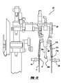
- FIG. 4 is a perspective view illustrating a machine for forming, filling and sealing the flexible pouch, according to the present invention.
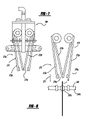
- FIG. 5 is an elevational view of a pouch opening station for the machine of FIG. 4 , according to the present invention.
- FIG. 6 is another elevational view of the pouch opening station of FIG. 5 , according to the present invention.
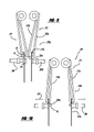
- FIG. 7 is a cross-sectional view of the zipper fingers in an open position prior to lowering into a pouch, according to the present invention.
- FIG. 8 is another cross-sectional view of the zipper fingers in a closed position, according to the present invention.
- FIG. 9 is a cross-sectional view of the zipper fingers lowered into the pouch, according to the present invention.
- FIG. 10 is a cross-sectional view of the opened pouch, according to the present invention.
- FIG. 11 is an elevational view of the opened pouch with the opening plunger, according to the present invention.
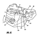
- FIG. 12 is a partial elevational view of the zipper fingers lowered into the pouch, according to the present invention.
- the filled pouch 10 may assume various shapes, such as cylindrical, cube, conical, spherical, or the like.
- the type of product and usage of the pouch influences the shape.
- the type of product is unlimited, and could have a solid or a liquid form.
- the pouch 10 may form one compartment for the product.
- the pouch 10 may include multiple discrete compartments.
- An example of such a pouch is disclosed in commonly assigned U.S. patent application Ser. No. 11/367,613, which is incorporated herein by reference.
- the flexible pouch 10 is preferably formed from a roll of flexible, preprinted laminate material.
- the choice of laminate material is nonlimiting, and is influenced by factors such as the product contained in the pouch 10 , the shape of the pouch or the anticipated use of the pouch.
- the laminate is either a three, four, five or more gauge material, and the outer layer is preprinted. It should be appreciated that a portion of the material may be a clear laminate as shown at 46 , in order to view the contents of the pouch.
- the laminate material may include at least one layer of virgin polyethylene terephthalate (PET) and at least one layer of aluminum foil (AL) and another layer such as EVOH, PET, polyethylene, or polypropylene or nylon or the like.
- the laminate may also include a metalized foil paper layer laminated to a cast polypropylene layer and another layer of PET, polyethylene or EVOH. It should be appreciated that there may be a fourth layer of nylon.
- Another material example includes a cast polypropylene (CPP) layer, a polyethylene (PET) layer, a foil (AL) layer, a nylon (ONO) layer and another CPP layer.
- CPP cast polypropylene
- PET polyethylene
- AL foil
- ONO nylon
- Another example of a material structure is the use of nylon, foil, nylon, and cast polypropylene (ONO/AL/ONO/CPP) or CPP/NY/AL/CPP.
- a further example of a laminate material structure is CPP/AL/ONO/PE.
- a pouch 10 made using the cast polypropylene laminate material retains its filled shape even as the product is removed from the pouch 10 . It should be appreciated that if a filled carbonated pouch is stored at ambient temperature, the laminate will start to creep after a period of time, such as ten days.
- the laminate material may include an extrusion layer to contain “creepage” or “stretch” of the film after filling due to carbonation expansion, if the product is carbonated.
- the laminate material may include another layer of sealable material, such as LDPE, to facilitate sealing.
- the selected material may be organoleptic compliant in order to avoid the transfer of odor contaminants to the product, or product contamination during the shelf life period of the product.
- the pouch 10 itself is defined by a panel, which may be formed using one or more sheets of material.
- the pouch 10 includes a front wall 12 and a back wall 14 , and the edges of the panel are joined along a seam 22 . With one sheet of material, the panel is manipulated so that its edges are joined together to form one seam.
- the pouch may be formed from two facing panels of material that are joined together along corresponding edges.
- the pouch generally defines an upper edge 16 , an opposed lower edge 18 , and at least one side edge 20 extending therebetween the upper and lower edges 16 , 18 .
- Any of the edges of the pouch may be shaped, such as linear or curvilinear or the like.
- the upper edge may include an elongated spout or neck portion.
- the edges of the pouch 10 may be sealed using heat or ultrasonics or by a combination of heat and ultrasonics.
- the pouch sealed edges form a seam 22 .
- the seam 22 may be a fin-style seam, or a flat seam or the like.
- a side edge seal may extend into a predetermined portion of the upper edge of the pouch, and a predetermined portion of the closing seal may overlap a predetermined portion of the side seal.
- the pouch 10 may include a feature such as a sidewall.
- the sidewall 26 advantageously allows the pouch 10 to acquire another shape, such as cylindrical, or to stand upright.
- the sidewall 26 may be integrally formed in the panel as a gusset or a separate piece of material as an insert.
- the sidewall may be located between any of the edges, such as the side edges of the panel, between the lower edges, between the upper edges, or a combination thereof.
- the sidewall may have a shape. For example a sidewall in a side edge may be generally wider at the lower edge and tapering upwardly towards the upper edge, or be of a uniform dimension.
- the sidewall may be formed between the lower edges of the pouch 10 to provide a base for the pouch 10 to stand upright.
- a sidewall formed may also serve as an area for receiving an opening means, such as between an upper edge.
- the inner surface of the gusset may have a curvilinear shape, such as parabolic, concave or the like.
- the rounded shape may be advantageous in opening and filling of the pouch, since a reduced amount of air may be utilized to open the pouch, depending on the size of the pouch of seals.
- the pouch includes an opening means 28 for accessing the contents or dispensing the contents from at least one compartment of the pouch 10 .
- opening means 28 are known in the art for this purpose. It should be appreciated that the opening means 28 may be incorporated into the pouch 10 prior to filling the pouch 10 . In addition, the pouch may be filled through an open edge of the pouch or through a fitment.
- an opening means is a tear-off portion 30 .
- the tear-off portion 30 usually has an integral tear notch 32 and tear line, for removing a designated portion of the pouch to access the product contained therein.
- the tear-off portion 30 could be utilized in conjunction with another opening means, such as a zipper 42 .
- the zipper opening means is a resealable zipper 42 that provides a hermetic seal through interlocking teeth, such as a zipper 42 that is sold under the name TopTiteTM.
- the zipper 42 may be used with another opening means.
- Another example of an opening means 28 is a weakened, straw-pierceable portion in the pouch for receiving a straw within at least one of the compartments.
- a further example of an opening means 28 is a pull tab covering an opening in the pouch.
- Still a further example of an opening means 28 is a fitment, such as a removable and replaceable cap 34 secured to a spout 36 .
- the spout fitment 36 may be mounted to the top
- the flexible pouch 10 may advantageously include other features that are known in the art.
- the pouch may include a tracking device 38 feature integrally located within the pouch 10 that includes electronic tracking information relevant to the pouch 10 , as described in commonly assigned U.S. patent application Ser. No. 11/686,666, which is incorporated by reference.
- the tracking device 38 may be an electronic tag, such as a Radio Frequency Identification (RFID) transmitter.
- RFID Radio Frequency Identification
- the tracking device 38 can store a predetermined amount of electronic information. An example of the information is unique tracking information for a particular package 10 .
- the tracking device 38 can provide information about the status of the pouch 10 , such as physical location of the pouch 10 , or age of the pouch 10 or the like.
- the tracking device 38 can be utilized for inventory control, delivery, purchase behavior, returns, pricing, and other tracking purposes.
- the tracking device 38 is in communication with a receiver (not shown) for reading the information.
- the receiver may be a computer system having a memory and a processor, a handheld device for receiving an RFID signal, or any other type of device capable of electronic communication with the tracking device 38 .
- the receiver may be a transceiver capable of emitting a radio signal that initiates transmission of information from the tracking device 38 .
- the packages are individually read, the RFID tag may be advantageously read at a faster rate than using a barcode in conjunction with a barcode scanner, since the packages are not physically scanned on an individual basis.
- the signal from the RFID tag may be advantageously read through an outer layer of material, such as a packaging material, or under various environmental conditions. Another advantage is that the tracking of the physical location of the package may be electronically monitored within a predetermined geographical range.
- the tracking device 38 may be integrally embedded in the pouch 10 .
- a plurality of apertures may be punched in the folded area of the gusset 26 to reduce the amount of material in the gusset 26 .
- the tracking device 38 may be inserted in an air pocket 40 formed within one of the gusset apertures. The inclusion of the tracking device 38 in the air pocket 40 is advantageous because it improves the signal strength of the tracking device 38 .
- the tracking device 38 may be inserted in a sealed portion of the pouch, and an air pocket 40 is formed around the tracking device 38 during application of the seal.
- the tracking device may be integrally formed in the opening means.
- the pouch 10 may include a feature such as an angled top seal 44 extending between a first side edge and a predetermined location on the upper edge 16 of the pouch.
- the angled top seal 44 facilitates the removal of product from the pouch 10 by directing the flow of the product towards the opening means.
- An example of such a pouch is disclosed in commonly assigned U.S. patent application Ser. No. 11/683,133 which is incorporated herein by reference.
- the pouch 10 may include a feature such as a hanging aperture 48 located within an edge, such as an upper edge or side edge.
- the aperture 48 may have various shapes, such as round or curved.
- the pouch 10 may be supported by a support means, such as a hook that extends through the aperture 48 .
- the pouch 10 may be hung for display or storage purposes. The positioning of the hanging aperture 48 above the angled top seal 44 or within a sealed portion prevents the contents of the pouch from leaking out through the aperture 46 .
- the pouch may include a feature such as a guide pocket formed in a wall 14 , 16 of the pouch 10 prior to filling and sealing, to facilitate the separation of the front and back walls 14 , 16 prior to the filling of the pouch 10 .
- a feature such as a guide pocket formed in a wall 14 , 16 of the pouch 10 prior to filling and sealing, to facilitate the separation of the front and back walls 14 , 16 prior to the filling of the pouch 10 .
- An example of such a pouch is disclosed in commonly assigned U.S. patent application Ser. No. 10/310,221.
- the pouch may contain a rib 50 that adds strength or support or form to the body of the pouch. The rib 50 may be thermoformed.
- the pouch may include a frangible seal. An example of a pouch with a frangible seal is disclosed in commonly assigned U.S. patent application Ser. No. 11/367,613 which is incorporated herein by reference.
- the pouch may include a feature such as an integral vent means 24 .
- the vent means such as a valve, functions to exhaust a gas from the pouch.
- the gas may be formed within the package while heating the pouch.
- the valve may also be operable to respire gas formed in the pouch for other reasons, such as gas formed by decaying food or during freezing or the like.
- the valve remains tightly closed, until pressure from the gas, such as steam, reaches a predetermined pressure value.
- the valve opens and remains open, to release the gas or stream from the package in a controlled manner.
- a tape may be used to cover a hole in the wall.
- a pressure relief device such as that manufactured by PPI Technologies Global, Sarasota, Fla.
- model number P033F may be utilized.
- Another example of a valve is disclosed in commonly assigned U.S. patent application Ser. Nos. 10/228,430 and 10/967,547 and PCT Patent Application No. PCT/US2004/34361 which is incorporated herein by reference.
- the pouch may include a feature such as an ergonomic shape.
- a feature such as an ergonomic shape.
- An example of an ergonomically shaped pouch for a carbonated beverage is disclosed in commonly assigned U.S. patent application Ser. No. 11/454,241 which is incorporated herein by reference.
- the ergonomic shape may be achieved through carbonation as the pouch 10 is filled with a carbonated product, since the carbonation causes the pressure within the pouch to increase.
- the flexible pouch 10 may include a feature such as an outer layer or sleeve (not shown) covering the outer surface of the pouch.
- the sleeve may be a label containing information about the product, such as a barcode or the like.
- the sleeve may cover only a portion of the pouch outer surface.
- the sleeve is shrunk over the outer surface of the pouch 10 after the pouch 10 is formed and filled with the product.
- the sleeve is advantageous because it covers the side seam. It also adds one or more layers of material to strengthen the pouch and improve its durability.
- Various types of material may be utilized for the sleeve, such as paper or plastic including PET or PVC and the choice is non-limiting.
- the filled pouch 10 may undergo a secondary process.
- the filled pouch may be refrigerated, frozen or otherwise modified for an extended shelf life.
- the filled pouch may be pasteurized for increased shelf life.
- pasteurized food products include dairy products such as milk, or meat products such as chicken or the like.
- the flexible pouch 10 may incorporate any of the above-described features or any other feature, in any combination.
- the finished pouch may assume various shapes, such as cylindrical, cubical, spherical, conical, and hourglass or the like, as influenced by the type of product and intended usage of the pouch. It should further be appreciated that the designated upper edge and lower edge is merely for reference purposes.
- the pouch 10 is available for filling, such as through an opening formed between open edges of the panels.
- the open edges of the pouch are sealed using a conventional method, such as heat sealing, or ultrasonic sealing or the like.
- the closing seal may be a single seal, or a wide double seal, as previously described. The sealed pouch is then available for shipping or additional processing.
- FIG. 3 a method for forming, filling and sealing the flexible pouch 10 , such as that described with respect to FIGS. 1 or 2 , using a high speed machine 200 as shown in FIGS. 4-11 is illustrated.
- the method may be implemented on various styles and combinations of machines, including be a form machine, a fill-seal machine, or a form-fill-seal machine.
- An example of a pouch forming machine is the Nishibe SMB500, SMB600 or SMB700.
- Another example is the Laudenberg form-fill-seal machine, FBM 10, 54, 20, 22.
- the method begins in block 100 at a first station with the step of forming the body of the pouch 10 .
- the body of the pouch may be formed from one or more panels of material that may be cut and positioned to form the front wall and a back wall of the pouch. Each wall panel has an inner surface and an outer surface, and an outer layer of the material 204 may include preprinted information.
- One layer of the material may also be preprinted with a tracking device 38 , such as the RFID transmitter previously described.
- a tracking device 38 such as the RFID transmitter previously described.
- several pouches are formed from one width of material. The material is removed from the roll, and may be cut into sections that are positioned to form the front wall and rear wall of the pouch.
- a roll of a preprinted laminate material as previously described is unrolled along a horizontally oriented plane.
- the initial width of the roll of material is determined by the desired finished size of the pouch and the number of pouches to be obtained from the width.
- two to four pouches representing four to eight wall panels can be obtained from a width of the roll of material on a machine having two or more lanes.
- the film may pass through an ultraviolet light chamber without reflection to remove pathogen and microbiological contaminants.
- the material may be aligned.
- a precise alignment is advantageous, especially at a higher machine speed since it allows for provide a more precise seam tolerance and a contaminant reduction in the amount of material required.
- An example of an alignment method is disclosed in commonly assigned U.S. patent application Ser. No. 11/674,923, which is incorporated herein by reference.
- An example of aligning the material includes modifying the planar orientation of the unrolling material 204 from a horizontal orientation to a vertical planar orientation. The vertical orientation is advantageous in aligning the unrolling material 204 prior to cutting.
- the machine 200 may utilize an angled roll bar to modify the planar orientation of the unrolling material.
- An optical reader device may be utilized, such as an optical scanner or the like to identify a predetermined location of the material, such as an edge of the material or a registration mark.
- the determined alignment of the unrolling material may be used to automatically correct the alignment of the unrolling material.
- a moveable roller may be utilized to adjust the alignment of the material along a vertically oriented axis. For example, the adjustment movement is ⁇ 2 degrees from the vertically oriented axis.
- a feature may be added to the pouch.
- a sidewall or gusset 26 may be inserted between the walls of the pouch.
- the gusset 26 fold or pleat is formed in the panel using a folding operation to fold the panel.
- the gusset may have a “V” shape, and in another example, the gusset has a “W” shape.
- a plurality of apertures may be formed in the gusset, such as by using a punch. The plurality of apertures may be positioned in the gusseted portion of the material, so as to reduce the amount of material in the gusseted portion of the pouch for sealing purposes.
- the tracking device 38 may be advantageously located within an airspace 40 created by the aperture.
- the RFID transmitter may be secured on a surface of the panel in a predetermined position, so that it is located in an air pocket created during a later step.
- a shaping means such as an insert may be positioned between the walls of the pouch.
- the shaping means may be positioned at any edge, such as a lower edge of the pouch or an upper edge. More than one shaping means may be utilized to achieve a desired shape.
- Still another example of a feature is a vent valve 24 inserted into one of the panels.
- an opening means 28 may be applied at this time to the panels.
- an opening means 28 such as a press-to-close zipper 42 may be applied to the panel walls 12 , 14 .
- the methodology advances to block 110 .
- a seal is applied to the pouch in a sealing operation.
- the seal can be a permanent seal, a temporary seal, a rib, or a frangible seal.
- Various types of seals are available, such as a single seal, a double seal, or an insulating seal, or the like.
- Various sealing techniques are known in the art to form each seal, and a combination of sealing techniques may be utilized.
- the seals may be a heat weld formed by applying heat and compression, or an ultrasonic seal formed using vibrational energy, or a combination of heat and ultrasonic seals. It should be appreciated that a previous seal may be absorbed during the sealing process.
- the side edges and lower edges of the pouch 10 may be sealed, leaving the upper edges open, or all of the edges may be sealed.
- the side seal may be an overlap seal, whereby the side seal extends along the side edge of the panel and a predetermined distance along the upper edge.
- An angled top seal 44 may also be applied at this time.
- the seals may be shaped. For example, a radius on an outer edge may be rounded to avoid a sharp edge. A radius on an interior edge facilitates removal of the product.
- a seal bar 229 or forming plate may be used to apply any of the seals.
- An example of a seal bar 229 is a generally rectangular member.
- the seal bar 229 may include a cavity used to create an air pocket, or to conform to the shape of a member.
- the seal bar or forming plate may have a plasma coating that makes the surface of the seal bar or forming plate more resilient. When the seal bar is heated, the coating expands due to this resiliency. The shear stress on the inner edge of the seal is reduced; resulting in reduced creepage of the material and greater durability of the seal.
- the plasma coating reduces the opportunity for potential damage to the material during the sealing step.
- the plasma coating is a smooth, hard plastic that mimics glass. Since the outer layer of material is not weakened, there is no creepage of the outer layer. An advantage of the plasma coating is that the line speed may increase.
- the side seal is a two-step seal formed using more than one seal bar.
- One seal bar may include the previously described seal bar cavity for forming an air pocket in the sealed portion.
- An example of a two-step seal is disclosed in commonly assigned U.S. patent application Ser. No. 11/551,071.
- the two-step seal advantageously avoids the generation of ketones due to application of heat to the material.
- the first or inner seal is a low temperature seal.
- the second or outer seal is a high temperature seal.
- the second seal is spaced apart from the first seal by a predetermined distance, to create an air gap.
- the first seal is a tack seal, such as 6 mm wide, and is of a sufficient temperature so as to melt the layers of material and tack the edges together.
- the predetermined distance between the first and second seal is 1 ⁇ 2-1 mm.
- the second seal is applied at a higher temperature and pressure than the first seal.
- any gas such as steam, ketones, aromatics or the like, is pushed in an outwardly direction, out through the open edges of the panels, and not into the pouch.
- the first seal prevents entry of contaminates into the pouch to avoid organoleptic contamination.
- the heat weld may include a heat weld followed by a cold weld. The methodology advances to block 115 .
- each section of material may be first separated along its width, i.e. along the side seams of the pouches.
- the section is then is separated into individual pouches along a cutting line.
- the width of unrolling material represents the side edges.
- the material is cut into a pouch 10 using a known cutting apparatus, such as a laser or punch or the like.
- the cutting apparatus imparts a single cut in the material to separate the pouches.
- a single widthwise and lengthwise cut separates the web into individual pouches.
- two rows of pouches are cut out at one time by adding a double cut between two lengthwise cuts, preferably in the center.
- separating out multiple pouches during the cutting operation effectively doubles the assembly line speed.
- two consecutive pouches 10 may be separated using a double cutting process, whereby two cuts are made at the same time to separate the upper and lower edges of two pouches at the same time from the sheet of material.
- separating multiple pouches during the cutting operation effectively increases the assembly line speed.
- the methodology advances to block 120 and the pouch is finished.
- an edge may be trimmed so that the pouch may acquire a predetermined shape, or the pouch corners may be shaped to have a radius, or the like.
- a hanging aperture 48 if present, may be formed at this time.
- the trimming operation may be performed using a cutter or a die cut or the like.
- a crease or guide pocket may be formed in a top portion of each wall 12 , 14 in a creasing operation, in order to facilitate opening and filling of the pouch.
- An example of a method of forming a crease in a wall to facilitate opening the pouch is disclosed in commonly assigned U.S. patent application Ser. No. 10/310,221, which is incorporated herein by reference.
- the sleeve is applied over the individual pouch and shrunk to fit using an application of heat to the pouch.
- a rib 50 may be added to the pouch. The rib may be thermoformed, and may provide the pouch 10 with shape or structure.
- the methodology advances to 125 , and the formed pouch 10 is removed from the form line by a transfer means.
- the fill-seal machine may be integral with the pouch forming machine, or may be a separate machine.
- the unfilled pouch may be loaded into a receptacle and the carrier is transferred to a fill-seal machine.
- the unfilled pouch may be directly placed on a fill-seal line using the transfer means.
- An example of a transfer means an individual, or a robotic transfer device, as disclosed in commonly assigned U.S. patent application Ser. No. 11/829,401, which is incorporated herein by reference.
- the pouches 10 may be temporarily stored in a receptacle such as a magazine between the forming and filling operations. This increases the flexibility of the machine and may result in a manufacturing cost savings.
- the pouch is loaded onto the fill-seal line or machine 258 .
- the fill-seal line 258 can be integral with the pouch forming machine, or a separate fill-seal machine.
- the fill-seal line 258 can have stations arranged in a linear manner, or rotary or another configuration.
- a line worker removes the pouch 10 from the form line or from the carrier, and places the pouch in a pouch carrier 262 on the fill-seal line 258 .
- a robotic transfer device 252 is used to transfer the pouch from the either form line 210 or the receptacle to the fill-seal line 258 .
- the robotic transfer device 252 can be a robotic device having an arm 254 and a gripping device 256 that picks up an individual pouch and places it in a pouch carrier 262 that moves between the fill-seal stations.
- a robotic device having an arm 254 and a gripping device 256 that picks up an individual pouch and places it in a pouch carrier 262 that moves between the fill-seal stations.
- An example is disclosed in commonly assigned U.S. patent application Ser. No. 11/829,401, which is incorporated herein by reference.
- Various types of pouch carriers 262 are available, such as a holder 262 or a gripper or the like.
- An example of a holder is a cup-shaped member, as disclosed in commonly assigned U.S. patent application Ser. No. 10/336,601, which is incorporated herein by reference.
- the methodology advances to block 135 , and the pouch 10 is partially opened in an opening operation.
- a pair of side edge grippers 264 hold the pouch along a side edge 20 .
- a pair of opposed panel grippers 266 are positioned adjacent each of the front panel and the rear panel respectively. In this example, the panel grippers 266 are located near an upper edge of the front panel and real panel.
- the panel grippers 266 are of the suction vacuum type. To partially open the pouch, the side edge grippers 264 move inwardly towards each other while the suction panel grippers 266 adjacent each panel move in an outwardly direction away from each other.
- the methodology advances to block 140 and the pouch is fully opened using a pouch opening device.
- the pouch opening device 270 includes a pair of pouch opening fingers 272 .
- the pouch opening fingers 272 are movable between an open position as shown at 274 a representing a maximum separation between the fingers, and closed position representing a minimum separation as shown at 274 b .
- the pouch opening finger pair includes an outer opening finger 272 a and an inner opening finger 272 b .
- the pouch opening finger pair 272 is initially located in a raised position above the partially open edges of the pouch as shown at 276 a and in an open pouch finger position 274 a .
- the inner opening fingers are adjacent each other, and the outer fingers are located outside the outer surface of each pouch wall.
- the opening fingers are lowered into the partially opened pouch as shown at 276 b , so that the inner pouch opening fingers 272 b are disposed between the open edges of the pouch, and each of the outer pouch opening fingers 272 a are adjacent an outer surface of each pouch wall, as shown in FIG. 9 .
- the inner pouch opening finger 272 b is displaceable towards the outer pouch opening finger 272 a , as shown at 275 .
- the pair of pouch opening fingers 272 surround and grab a respective pouch wall.
- Each pair of pouch opening fingers 272 is displaced together in an outward direction, as shown at 278 to fully open the pouch by separating the walls of the pouch, as shown in FIG. 10 .
- a pouch opening member 280 may be used to insure the fitment is fully opened. For example a plunger is lowered into the opened pouch.
- the pouch opening member 280 opens a zipper profile by moving back and forth along the length of the zipper, as shown in FIG. 5 , in order to separate the teeth of the zipper and provide access to the interior of the pouch.
- a nozzle may be mechanically lowered into each pouch to direct a stream of compressed gas into the pouch, to force the walls of the pouch 10 away from each other.
- An example of a gas is carbon dioxide or nitrogen.
- the opening station may also include a blowing station having a manifold with a hood extending over the top of (not shown) the upper edges of the pouch 10 , as is known in the art.
- the manifold has rows of apertures (not shown) formed above the upper edges of the pouch.
- the hood may be placed over the pouch 10 to assist in maintaining the air pressure in the pouch 10 .
- the supply of pressurized gas is directed through the aperture to form a plurality of jets of pressurized gas or air.
- the jets are directed downwardly at the diamond-shaped openings formed at the upper edges to further assist in overcoming the surface tension of the pouch and assist in separation of the walls of each compartment.
- a diving rod (not shown) may then be used to make sure the pouch 10 is fully opened.
- the inner pouch opening fingers 272 return to the initial open finger position and the panel gripper and side edge gripper moves away from the pouch. It should be appreciated that the open zipper may be confirmed using a detect switch. The methodology advances to block 145 .
- the pouch 10 is filled with the product in a filling operation.
- a fill tube is lowered into the pouch a predetermined distance and the product is dispensed into the opened pouch.
- the product is preferably dispensed at a predetermined temperature, depending on the type of product.
- the fill tube may be raised out of the pouch at a predetermined rate as the product is dispensed.
- the fill tube may be removed just ahead of the filling product.
- the pouch is preferably filled while immersed in a nitrogen or carbon dioxide atmosphere.
- the product is not naturally carbonated and carbonation is desirable, it is immersed in a carbonator to introduce carbon dioxide into the product.
- carbon dioxide is introduced into cold water or juice to provide a carbonated beverage.
- the product may contain a mixture of up to four volumes of carbon dioxide. It should be appreciated that the carbon dioxide masks any undesirable taste from ketones and other solvents released during the sealing process.
- the carbon dioxide also increases the pressure within the product so that the walls of the pouch are rigid after the top is sealed.
- the product is preferably filled at a temperature ranging from 29 OF to ambient temperature.
- the filled pouch may have the oxygen removed from the pouch.
- the pouch may be flushed with carbon dioxide. Any gas in the head space of the pouch is removed.
- oxygen may be removed by applying a vacuum.
- the pouches 10 may be moved to a station where any oxygen in the pouch residing above the product is removed, if necessary. This can be done by providing a hood or diving nozzle where oxygen is either evacuated or replaced with carbon dioxide or nitrogen into the pouch to displace the oxygen. A diving nozzle is used to inject the gas. The methodology advances to block 150 .
- the pouch is closed.
- Various techniques are available for sealing the pouch 10 .
- the seal technique depends on the product contained in the pouch, the pouch shape, or type of opening means or how the pouch is filled.
- the closing seal may be an ultrasonic seal or an ultra pulse seal or a heat weld or the like.
- a closing seal 52 may be applied to the portion of the pouch outboard of the zipper, to seal the upper edges 16 together using a closing sealing process as previously described.
- the open edges of the pouch are closed by applying a first closing seal.
- the first closing seal may be an ultrasonic seal, or an ultra pulse seal.
- An example of a closing seal for a pouch containing a carbonated product is described in commonly owned PCT Patent Application No. PCT/US03/034396 which is incorporated herein by reference.
- a second closing seal may be applied a predetermined distance apart from the first seal.
- the second seal may be a heat weld or a cosmetic seal or an ultrasonic seal or the like.
- the location of the second seal is selected so that some of the product is trapped between the first and second seals. This is advantageous since it eliminates the potential for gas in the head space, i.e. the region between the product and the heat seal.
- the second seal is spaced outboard of the first seal. Another advantage of the location of the second seal is that the overall length of the pouch may be reduced, resulting in less pouch material.
- the first closing seal is a tack seal
- the second closing seal is a high pressure, high temperature seal.
- a cosmetic seal may be applied with respect to the first and second closing seals, or the second seal may be a cosmetic seal. In an example of an overlap seal, the closing seal extends a predetermined amount over the side seal along the upper edge.
- the cap 34 is applied the spout 36 to close the pouch 10 .
- the cap 34 contains the product in the filled pouch, to prevent leakage of the product from the pouch 10 .
- the cap 34 may be a tamper-evident cap for a carbonated product.
- the filled pouch 10 is finished in a finishing operation.
- the edges of the pouch may be trimmed to achieve a predetermined pouch shape.
- the filled pouch may be cooled at a cooling station using a conventionally known cooling technique.
- the sleeve may be placed over the filled pouch and shrunk to fit over the pouch by applying heat.
- the sleeve layer forms an outer layer of the pouch. The methodology advances to block 160 .
- the filled pouch 10 is discharged from the machine.
- a plurality of pouches may be placed in a package for sales or shipping purposes.
- the pouch is available for additional processing if desired.
- the pouches are moved to a discharge station 232 .
- a robotic transfer device 252 may be used to remove the pouch from the carrier 262 .
- the carriers may then be moved by the conveyor through a rinsing station and returned to the other side of the machine for use.
- the pouches 10 may be placed into cartons.
- the filled pouch is available for distribution or additional processing.
- the filled pouch may be pasteurized in an integral retort chamber (not shown) that heats and then cools the pouch.
- the pouch may be tested, such as burst testing or the like prior to packaging for shipping.
- a manufacturing station may perform one or a plurality of operations, to enhance the efficiency of the methodology and apparatus.
- the methodology may include other steps, such as an upstream oxygen purging station, a downstream oxygen purging station, or pasteurization or the like. It is also contemplated that the order of implementing the steps may vary to facilitate the manufacturing process.
- FIGS. 4-11 a machine 200 for carrying out the method described with respect to FIG. 3 for the pouch of FIGS. 1-2 is illustrated.
- Various styles of machines 200 are contemplated for forming or filling and sealing the pouch 10 , such as a flat bed, conveyor or the like.
- An example of such a machine is manufactured by Nishibe, such as the model number SBM500, SMB600 or SMB700.
- the machine 200 may include form stations 210 and/or fill-seal stations 258 . It should be appreciated that a particular manufacturing station may perform one or a plurality of operations, to enhance the efficiency of the methodology and apparatus.
- the stations may be arranged in a linear manner, rotary manner, or a combination thereof.
- the machine includes a base 216 and a transport device 212 that transports the material through the various stations.
- Various styles of transport devices are contemplated, and a particular machine may include more than one style.
- An example of a transport device is a conveyor, rollers, a turret or the like.
- the roll of material 204 is initially mounted along a horizontally oriented axis, and is unrolled along at a material feed station.
- the machine 200 includes an alignment station 218 that aligns the unrolling material 204 .
- the material rolls pass through sensing device, such as an optical reader, that identifies a predefined point on the material 204 .
- This predefined point may be a registration mark on the material, or the edge of the material 204 .
- the machine 200 utilizes the registration marks to automatically adjust the orientation of the unrolling material position along an axis.
- rollers 220 are used to adjust the position of the unrolling material ⁇ 2 degrees relative to a vertically oriented center axis.
- the machine may include a fitment application station 222 that applies an opening means 28 , such as a zipper fitment to the unrolling material at a predetermined location on the material.
- the machine includes a feeder mechanism 223 , which supplies the zipper 42 to the machine.
- a feeder mechanism 223 supplies the unrolling material roll with pre-applied zipper at a 90 degree angle to the direction of material 204 flow.
- the zipper fitment may be simultaneously applied across all lanes in the predetermined panel location. For example, in a 10 lane machine with 10 panels, arranged in a linear line of 10, 10 fitments are simultaneously sealed to the material. At a rate of 50 strokes per minute, 500 fitments per minute may be applied to the unrolling material.
- the machine includes a cutting station 224 where the material is cut into a predetermined number of sections.
- a cutting station 224 where the material is cut into a predetermined number of sections.
- one of the sections is rotated 180 degrees, and the first and second sections of this example are positioned such that inner sides face one another.
- the sections are used to form the front panel and back panel of the pouch, respectively.
- the machine may include a feature insertion station that adds a feature, as previously described, between the facing sheets of material.
- the facing sections are transferred along the conveyer to a sealing station.
- the machine includes a sealing station 228 that applies a seal to the pouch.
- a sealing station 228 that applies a seal to the pouch.
- the seal may be a heat weld formed by applying heat and compression, or an ultrasonic seal formed using vibrational energy, or a combination of heat and ultrasonic seals.
- a previous seal may be absorbed during the sealing process.
- An example of some applications includes to seal an edge of the pouch, secure a fitment to the pouch, form a rib or another thermoformed feature.
- the sealing station may include a seal bar 229 to apply the seal.
- the seal bar may include a cavity surface that corresponds to a predetermined shape.
- the cavity may be for sealing a fitment, or creating an airspace or the like.
- the sealing station 228 may form the seams joining the edge of each panel to delineate each pouch.
- the side edges of each of the pouches along the width of material are heat-sealed. By precise alignment of the material sheets, the width of the side edge seam may be reduced, such as 4 mm, with a tolerance of ⁇ 1 mm.
- the machine includes a cutting station 230 and the sealed panels are separated into individual pouches.
- the pouch is separated along an edge seam.
- the pouch may also be separated from the unrolling material along the upper edge and lower edge.
- the cut may be a double cut, so as to separate two pouches at one time. It should be appreciated that the pouches 10 are fully formed, and are now ready for filling.
- the machine includes an unloading station 232 .
- the transport device transfers the individual pouches to an unloading station 232 , wherein the individual pouches are removed.
- the pouches may be placed into a receptacle, such as a holder, or magazine or the like.
- the pouches may be placed directly on a fill-seal line 258 associated with the machine, using a robotic transfer device 252 , as previously described.
- the line speed between the form stations 210 and the fill-seal stations 258 can be coordinated to output filled pouches at a predetermined rate, and such coordination may increase the overall pouch production rate.
- the fill-seal line 258 includes a pouch receiving station 234 for receiving the pouch that includes a pouch carrier 262 that moves the pouch, arranged in a predetermined manner, through each of the stations in the fill-seal line 258 .
- the fill-seal stations may be associated with a second frame 284 .
- the stations of the fill seal line 258 of the machine 200 may be arranged in various configurations, such as a linear manner, or a circular manner.
- An example of a circular transport means is a rotational transport table.
- the linearly arranged stations may be further oriented transversely or vertically.
- Various types of pouch carriers are available, such as a holder 262 or a gripper, a combination thereof or the like.
- An example of a holder 262 is a cup-shaped member, as disclosed in commonly assigned U.S. patent application Ser. No. 10/336,601, which is incorporated herein by reference.
- a pair of opposed side edge grippers 264 each hold a corresponding side edge of the pouch.
- the side edge grippers 264 may be operatively connected to an actuating device 268 for displacing the side edge gripper in the manner described to open the pouch.
- the holder 262 is operatively connected to a transport device 282 , as previously described, for moving the pouch carrier between stations.
- the machine includes an opening station 236 , in order to separate the upper edges of the pouch for filling.
- the opening station 236 includes panel grippers 266 that grip the outside panels of the pouch.
- the panel gripper 266 includes a gripping member 267 a positioned on an end of an arm 267 b .
- the arm is attached to an actuating device 268 for simultaneously moving the panel gripper 266 and side edge grippers 264 in predetermined directions.
- the gripping member 267 a is a suction cup that relies on the creation of a vacuum in order to grip the pouch.
- Other types of gripping members may be used, such as fingers or the like.
- each panel gripper 266 is adjacent an outer surface of the front wall 12 and back wall 14 respectively.
- the panel grippers 266 are located near an uppermost edge of the front wall 12 and back wall 14 .
- the side edge grippers 264 are moved inwardly towards each other as shown at 263 while the panel grippers 266 holding the outer surface of each panel are displaced in an outwardly direction perpendicular or to the orientation of the pouch as shown at 275 .
- the opening station 236 also includes a pouch opening device 270 for fully opening the pouch.
- the pouch opening device 270 includes at least one pair of pouch opening fingers 272 .
- the pouch opening finger pair 272 includes an outer opening finger 272 a and an inner opening finger 272 b .
- each of the pouch opening fingers 272 is a generally rectangular bar.
- a lower end of the bar may include a gripping surface 272 c that is in contact with the pouch.
- the upper end of the bar is secured to actuating device 268 .
- the actuating device 268 controls the movement of the pouch opening device between various positions, such as a finger open position 274 a , a finger closed position 274 b , a finger raised position 276 a and a finger lowered position 276 b or an outward opening position 278 .
- the actuating device includes a motor, a controller or other actuating linkage, or the like utilized mechanisms for performing the desired opening operation in a predetermined sequence.
- the finger closed position 274 b represents a minimum separation between a pair of fingers to grip the pouch wall, and the finger open position 274 a representing a maximum separation between a pair of fingers.
- the pairs of pouch opening fingers initially have an open finger position 274 a , and are located in a raised position 276 a above the partially open edges of the pouch.
- an edge of each of the inner opening fingers are adjacent each other, and an edge 272 c each of the outer fingers are located adjacent the outer surface of each pouch wall.
- the actuating device 268 lowers the pair of pouch opening fingers 272 into the partially opened pouch in the direction shown at 271 of FIG.
- each of the inner fingers 272 b is adjacent an inner surface of the pouch wall
- the gripping surface 272 c of the outer fingers 272 a are positioned adjacent an outer surface of each pouch wall, into the partially opened pouch, as shown in FIG. 9 .
- the pair of pouch opening fingers 272 come together to grip the wall disposed therebetween, and the actuating mechanism 268 operatively displaces each pair of pouch opening fingers in an opposite direction away from each other as shown at 278 , i.e. an outward direction, to fully open the pouch by separating the walls of the pouch, as shown in FIG. 10 .
- the opening station 236 also includes a pouch opening member 280 operatively controlled by the actuating mechanism 268 .
- the pouch opening member includes an arm 280 a and a head 280 b located on a distal end of the arm 280 a .
- the proximate end of the arm is secured to the actuating mechanism, for displacement of the pouch opening member into the pouch.
- the head portion may assume various shapes, depending on the type of fitment.
- the head portion 280 b is a plunger which has a semi-spherical shape.
- the actuating device 268 positions the opener 280 b between the open edges of the pouch to insure the fitment is open.
- the pouch opening member 280 insures the zipper is open by simultaneously moving up and down while traveling back and forth along the length of the zipper, as shown at 281 in FIG. 5 , in order to separate the teeth of the zipper and provide access to the interior of the pouch.
- a stream of heated air may be directed toward the upper edges of the pouch, or through the spout.
- a nozzle may be mechanically lowered into the pouch opened 10 .
- the nozzle is secured to a gas supply means.
- a stream of compressed gas downwardly into the pouch to further force the walls of the pouch 10 away from each other to further the pouch as shown at 238 .
- An example of a gas is carbon dioxide or nitrogen.
- the opening station 238 may include a manifold, with a hood extending over the top of the edges of the pouch.
- the manifold has rows of apertures (not shown) formed above the upper edges of the walls of the pouch.
- the hood is placed over the pouch to assist in maintaining the air pressure in the pouch.
- the supply of pressurized gas is directed through the aperture to form a plurality of jets of pressurized gas or air.
- the jets are directed downwardly at the diamond-shaped openings formed at the upper edges to assist in overcoming the surface tension of the walls and assist in separation of the walls.
- a diving rod may then be used to make sure the pouch is fully opened. Steam or another type of sterilizer may be utilized to clean an inside wall of the opened pouch.
- the opened pouch moves to a filling station 240 , and the pouch is filled with the product.
- a product is stored in a storage device, and one end of a feed line is in communication with the product in the storage device. The other end of the feed line is secured to a nozzle that dispenses a predetermined amount of product into the opened pouch.
- the product may be dispensed directly through the opened edges of the pouch or through the spout.
- the feed line is operatively controlled by an actuator that lowers the nozzle into the opened pouch, and dispenses the product into the opened pouch.
- the nozzle may be raised at a predetermined rate out of the pouch that corresponds to the rate of filling the pouch.
- the controlled delivery of product may reduce any overspray.
- the pouch may be filled while immersed in a nitrogen atmosphere.
- the product may be immersed in a carbonator to introduce carbon dioxide into the product.
- carbon dioxide is introduced into cold water or juice to provide a carbonated beverage.
- the product may contain a mixture of up to four volumes of carbon dioxide. It should be appreciated that the carbon dioxide may also mask any undesirable taste from ketones and other solvents released during the sealing process.
- the carbon dioxide also increases the pressure within the product so that the walls of the pouch 10 are rigid after the top is sealed.
- the product is preferably filled at a temperature ranging from 29° F. to ambient temperature.
- the carbonation is also advantageous as a microbiocide that can enhance the flavor or prevent mold or contamination.
- the machine includes a gas removal station for removing any oxygen from the pouch as shown at 242 .
- the gas removal station may include a hood that evacuates the oxygen, or a diving nozzle that delivers a gas, such as carbon dioxide or nitrogen, or liquid nitrogen or the like, into the pouch to displace the oxygen.
- the machine includes a closing station 244 that closes the pouch.
- the filled pouch may also return to a partially closed position due to the product contained therein.
- the grippers are moved in a direction opposite the pouch, to close the upper edge of the pouch by increasing the tension in the walls of the pouch.
- a pouch includes a zipper fitment
- the zipper is closed using a closing apparatus that engages the zipper, and a portion of the pouch outboard of the zipper may be sealed.
- the closed edges of the pouch are sealed using a closing seal.
- the closing seal may be a thermal seal.
- a moveable heat sealing member is positioned over the upper edge of the pouch to seal the upper edges together through the application of heat or heat and pressure.
- the heat sealing member may have a plasma coating.
- Another example of a closing seal for a product utilizes an ultrasonic sealing process that includes a first closing seal.
- the ultrasonic seal may include sound waves and is formed using a horn and anvil.
- the machine may include a second closing station for applying a second closing seal.
- the second closing seal may be applied using a heat seal means to form a second heat seal spaced apart a predetermined distance from the first closing seal. It should be appreciated that the second closing seal may be spaced slightly outboard of the first closing seal.
- the second heat-sealing station is conventional and utilizes heat or a combination of heat and pressure to form the seal.
- the second closing seal may also be a cosmetic seal or another type of seal, such as ultrasonic, ultra pulse or the like.
- the first and second seals are applied for a carbonated product as disclosed in commonly assigned Patent Application No. PCT/US03/34396, which is incorporated herein by reference.
- the pouch 10 is filled through the spout fitment 36 , the pouch 10 is closed by securing a cap 34 to the spout 36 using a cap application device.
- the cap 34 may have a tamper-evident feature.
- the cap 34 may contain a tracking device 38 .
- the machine includes a removal station 246 for finishing and removing the pouch from the machine 200 .
- a feature such as a hanging aperture 48 , may be formed at this time using a cutting device, such as a punch.
- the edges of the pouch 10 may be trimmed to achieve a desired shape using a cutting device.
- the machine includes a pouch transfer device such as a robotic transfer device for removing the pouches 10 from the machine 200 .
- the pouch may be placed into a box or moved to another device or machine for additional processing.
- the automated machine 200 may include other operations.
- the filled pouch may be transferred to another transport device, or otherwise collected.
- other stations may include a straw pierceable opening station, an upstream oxygen purging station, downstream oxygen purging station, or the like.
- the pouch is transferred to a packaging machine, which may be integral with the fill-seal machine or a separate line.
- the pouch may be transferred to a pasteurization station. Pasteurization enhances the shelf life of the product.
- the pouch is inserted into an enclosed chamber. For example, a combination of steam and water is used to heat the pouch to a predetermined temperature for a predetermined period of time to pasteurize the product contained within the pouch.
- the package is then cooled.
- recirculated water surrounds the pouch cool the pouch.
Abstract
Description
- This application claims priority of U.S. Provisional Patent Application Ser. No. 60/863,864 filed Nov. 1, 2006, which is incorporated herein by reference.
- 1. Field of the Invention
- The present invention relates generally to a flexible pouch for packaging products, and more particularly to a method and apparatus for opening a flexible pouch using a pair of opening fingers.
- 2. Description of the Related Art
- Various types of disposable, portable containers are known in the art for storing a fluid or dry product, such as a liquid, granular material, powder or the like. An example of such a container is a flexible pouch. Consumers prefer the convenience of flexible pouches over other types of containers, due to their shape, size, shelf life and storage adaptability. Manufacturers recognize the packaging benefits of a flexible pouch, since the pouch can be formed and filled on the same manufacturing line. An example of a method and apparatus for filling a flexible pouch with a product is disclosed in commonly assigned U.S. Pat. No. 6,199,601, which is incorporated herein by reference.
- The pouch may be formed through conventionally available manufacturing techniques using a machine. Various styles of machines can be utilized, such as a form machine, or fill-seal machine, or form-fill-seal machine. The machine can have various configurations, such as horizontal, vertical or flat bed, or the like, as well as a single or multiple lanes. The machine can include various stations, with a particular operation or operations taking place at each station. The formed pouch may be opened, filled, sealed and finished as required for a particular style of pouch. Various techniques are used to open the pouch, such as grippers, diving rods, or gas or a combination thereof.
- While all of these opening techniques work, the pouch may not be fully opened prior to filling, depending on the configuration of the pouch. Thus, there is a need in the art for an improved apparatus and method of reliably opening a flexible pouch using a pair of opening fingers, in order to fully open the pouch and fill the pouch with a product.
- Accordingly, an apparatus, method and machine for opening a flexible pouch are provided. The apparatus is an opening station that includes a pair of opposed side grippers each holding a side of the pouch and operatively connected to an actuating mechanism. A pair of opposed panel grippers each hold an upper edge of the pouch. The actuating mechanism simultaneously displaces the side grippers inwardly towards each other and the panel grippers outwardly away from each other to partially open the pouch. A pair of pouch opening fingers are displaceable between a raised position above the pouch and a lowered position within the pouch. The pair of pouch opening fingers are open in the raised position and closed after the pouch is lowered into the pouch to grip the wall of the pouch. The pouch opening fingers move together a predetermined distance in an outboard direction to fully separate the pouch walls.
- The machine for opening, filling with a product and closing a flexible pouch contained within the pouch includes a receiving station for receiving an unfilled flexible pouch having a wall and an opening means integrally formed in the wall for accessing a product. The machine includes a pair of opposed side grippers each holding a side of the pouch for transporting the pouch between stations of the machine. The machine includes an opening station having an actuating mechanism and a pair of opposed panel grippers operatively connected to an actuating mechanism that each hold an upper edge of the pouch, and a pair of pouch opening fingers operatively connected to the opening station actuating mechanism that are displaceable between a raised position above the pouch and a lowered position within the pouch, and an outboard direction to fully open the pouch. The machine further includes a filling station for filling the opened pouch with the product and a closing station for closing the pouch opening means.
- The method includes the steps of providing a formed pouch having a wall and an opening means integrally formed in the wall for accessing a product contained within the pouch. The pouch is partially opened using a pair of opposed side grippers, each holding a side of the pouch, a pair of opposed panel grippers, each holding an upper edge of the pouch. The side grippers are displaced inwardly towards each other and the panel grippers are displaced outwardly away from each other to partially open the pouch. The pouch is fully opened by displacing a pair of pouch opening fingers into the partially opened pouch from a raised position above the pouch to a lowered position within the pouch. The pouch opening fingers are open in the raised position, and closed after being lowered into the pouch, to grip the wall of the pouch, and the pouch opening fingers move together in an outboard direction to fully open the pouch.
- One advantage of the present invention is that an improved apparatus and method and machine for opening a flexible pouch for filling with a product using a pouch opening finger is provided. Another advantage of the present invention is that an apparatus, method and machine for making a flexible pouch is provided that utilizes a pair of fingers to open the pouch prior to filling. Still another advantage of the present invention is that an apparatus, method and machine for making a flexible pouch is provided that includes a pouch opening device or plunger, to more fully and reliably opens a pouch with a zipper. A further advantage of the present invention is that an apparatus, method and machine for making a flexible pouch with a pouch opening finger is provided that is cost effective to manufacture and implement. Still yet a further advantage of the present invention is that an apparatus, method and machine is provided that can be utilized with a multi-compartment pouch.
- Other features and advantages of the present invention will be readily appreciated, as the same becomes better understood after reading the subsequent description taken in conjunction with the accompanying drawings.
-
FIG. 1 is an elevational view of a flexible pouch with a zipper fitment, according to the present invention. -
FIG. 2 is an elevational view of a flexible pouch with a spout fitment, according to the present invention. -
FIG. 3 is a flowchart illustrating a method of forming and filling the flexible pouch, according to the present invention. -
FIG. 4 is a perspective view illustrating a machine for forming, filling and sealing the flexible pouch, according to the present invention. -
FIG. 5 is an elevational view of a pouch opening station for the machine ofFIG. 4 , according to the present invention. -
FIG. 6 is another elevational view of the pouch opening station ofFIG. 5 , according to the present invention. -
FIG. 7 is a cross-sectional view of the zipper fingers in an open position prior to lowering into a pouch, according to the present invention. -
FIG. 8 is another cross-sectional view of the zipper fingers in a closed position, according to the present invention. -
FIG. 9 is a cross-sectional view of the zipper fingers lowered into the pouch, according to the present invention. -
FIG. 10 is a cross-sectional view of the opened pouch, according to the present invention. -
FIG. 11 is an elevational view of the opened pouch with the opening plunger, according to the present invention. -
FIG. 12 is a partial elevational view of the zipper fingers lowered into the pouch, according to the present invention. - Referring to
FIGS. 1-2 , aflexible pouch 10 is illustrated. The filledpouch 10 may assume various shapes, such as cylindrical, cube, conical, spherical, or the like. The type of product and usage of the pouch influences the shape. The type of product is unlimited, and could have a solid or a liquid form. Thepouch 10 may form one compartment for the product. Alternatively, thepouch 10 may include multiple discrete compartments. An example of such a pouch is disclosed in commonly assigned U.S. patent application Ser. No. 11/367,613, which is incorporated herein by reference. - The
flexible pouch 10 is preferably formed from a roll of flexible, preprinted laminate material. The choice of laminate material is nonlimiting, and is influenced by factors such as the product contained in thepouch 10, the shape of the pouch or the anticipated use of the pouch. Preferably, the laminate is either a three, four, five or more gauge material, and the outer layer is preprinted. It should be appreciated that a portion of the material may be a clear laminate as shown at 46, in order to view the contents of the pouch. For example, the laminate material may include at least one layer of virgin polyethylene terephthalate (PET) and at least one layer of aluminum foil (AL) and another layer such as EVOH, PET, polyethylene, or polypropylene or nylon or the like. The laminate may also include a metalized foil paper layer laminated to a cast polypropylene layer and another layer of PET, polyethylene or EVOH. It should be appreciated that there may be a fourth layer of nylon. Another material example includes a cast polypropylene (CPP) layer, a polyethylene (PET) layer, a foil (AL) layer, a nylon (ONO) layer and another CPP layer. Another example of a material structure is the use of nylon, foil, nylon, and cast polypropylene (ONO/AL/ONO/CPP) or CPP/NY/AL/CPP. A further example of a laminate material structure is CPP/AL/ONO/PE. This structure works well when the product has a short shelf life, and the nylon eliminates stretching or cracking of the AL layer. Advantageously, apouch 10 made using the cast polypropylene laminate material retains its filled shape even as the product is removed from thepouch 10. It should be appreciated that if a filled carbonated pouch is stored at ambient temperature, the laminate will start to creep after a period of time, such as ten days. The laminate material may include an extrusion layer to contain “creepage” or “stretch” of the film after filling due to carbonation expansion, if the product is carbonated. The laminate material may include another layer of sealable material, such as LDPE, to facilitate sealing. In addition, the selected material may be organoleptic compliant in order to avoid the transfer of odor contaminants to the product, or product contamination during the shelf life period of the product. - The
pouch 10 itself is defined by a panel, which may be formed using one or more sheets of material. Thepouch 10 includes afront wall 12 and aback wall 14, and the edges of the panel are joined along aseam 22. With one sheet of material, the panel is manipulated so that its edges are joined together to form one seam. In another example of a pouch formed from two sheets of material, the pouch may be formed from two facing panels of material that are joined together along corresponding edges. These examples are merely illustrative of pouch shapes, and other pouch shapes may be utilized. - Further, the pouch generally defines an
upper edge 16, an opposedlower edge 18, and at least oneside edge 20 extending therebetween the upper andlower edges - The edges of the
pouch 10 may be sealed using heat or ultrasonics or by a combination of heat and ultrasonics. The pouch sealed edges form aseam 22. Theseam 22 may be a fin-style seam, or a flat seam or the like. In an example of an overlap seam, a side edge seal may extend into a predetermined portion of the upper edge of the pouch, and a predetermined portion of the closing seal may overlap a predetermined portion of the side seal. - The
pouch 10 may include a feature such as a sidewall. Thesidewall 26 advantageously allows thepouch 10 to acquire another shape, such as cylindrical, or to stand upright. Thesidewall 26 may be integrally formed in the panel as a gusset or a separate piece of material as an insert. The sidewall may be located between any of the edges, such as the side edges of the panel, between the lower edges, between the upper edges, or a combination thereof. The sidewall may have a shape. For example a sidewall in a side edge may be generally wider at the lower edge and tapering upwardly towards the upper edge, or be of a uniform dimension. The sidewall may be formed between the lower edges of thepouch 10 to provide a base for thepouch 10 to stand upright. A sidewall formed may also serve as an area for receiving an opening means, such as between an upper edge. - In an example of a sidewall forming a gusset between the lower edges of the pouch, the inner surface of the gusset may have a curvilinear shape, such as parabolic, concave or the like. For a pouch having a predetermined size the rounded shape may be advantageous in opening and filling of the pouch, since a reduced amount of air may be utilized to open the pouch, depending on the size of the pouch of seals.
- The pouch includes an opening means 28 for accessing the contents or dispensing the contents from at least one compartment of the
pouch 10. Various types of opening means 28 are known in the art for this purpose. It should be appreciated that the opening means 28 may be incorporated into thepouch 10 prior to filling thepouch 10. In addition, the pouch may be filled through an open edge of the pouch or through a fitment. - One example of an opening means is a tear-
off portion 30. The tear-off portion 30 usually has anintegral tear notch 32 and tear line, for removing a designated portion of the pouch to access the product contained therein. The tear-off portion 30 could be utilized in conjunction with another opening means, such as azipper 42. The zipper opening means is aresealable zipper 42 that provides a hermetic seal through interlocking teeth, such as azipper 42 that is sold under the name TopTite™. Thezipper 42 may be used with another opening means. Another example of an opening means 28 is a weakened, straw-pierceable portion in the pouch for receiving a straw within at least one of the compartments. A further example of an opening means 28 is a pull tab covering an opening in the pouch. Still a further example of an opening means 28 is a fitment, such as a removable andreplaceable cap 34 secured to aspout 36. Thespout fitment 36 may be mounted to the top portion or side portion of the wall. - It should be appreciated that the
flexible pouch 10 may advantageously include other features that are known in the art. For example, the pouch may include atracking device 38 feature integrally located within thepouch 10 that includes electronic tracking information relevant to thepouch 10, as described in commonly assigned U.S. patent application Ser. No. 11/686,666, which is incorporated by reference. Thetracking device 38 may be an electronic tag, such as a Radio Frequency Identification (RFID) transmitter. Thetracking device 38 can store a predetermined amount of electronic information. An example of the information is unique tracking information for aparticular package 10. For example, thetracking device 38 can provide information about the status of thepouch 10, such as physical location of thepouch 10, or age of thepouch 10 or the like. In addition, thetracking device 38 can be utilized for inventory control, delivery, purchase behavior, returns, pricing, and other tracking purposes. Thetracking device 38 is in communication with a receiver (not shown) for reading the information. The receiver may be a computer system having a memory and a processor, a handheld device for receiving an RFID signal, or any other type of device capable of electronic communication with thetracking device 38. The receiver may be a transceiver capable of emitting a radio signal that initiates transmission of information from thetracking device 38. Although the packages are individually read, the RFID tag may be advantageously read at a faster rate than using a barcode in conjunction with a barcode scanner, since the packages are not physically scanned on an individual basis. In addition, the signal from the RFID tag may be advantageously read through an outer layer of material, such as a packaging material, or under various environmental conditions. Another advantage is that the tracking of the physical location of the package may be electronically monitored within a predetermined geographical range. - The
tracking device 38 may be integrally embedded in thepouch 10. For example, a plurality of apertures may be punched in the folded area of thegusset 26 to reduce the amount of material in thegusset 26. Thetracking device 38 may be inserted in anair pocket 40 formed within one of the gusset apertures. The inclusion of thetracking device 38 in theair pocket 40 is advantageous because it improves the signal strength of thetracking device 38. Alternatively, thetracking device 38 may be inserted in a sealed portion of the pouch, and anair pocket 40 is formed around thetracking device 38 during application of the seal. The tracking device may be integrally formed in the opening means. - The
pouch 10 may include a feature such as an angledtop seal 44 extending between a first side edge and a predetermined location on theupper edge 16 of the pouch. The angledtop seal 44 facilitates the removal of product from thepouch 10 by directing the flow of the product towards the opening means. An example of such a pouch is disclosed in commonly assigned U.S. patent application Ser. No. 11/683,133 which is incorporated herein by reference. - The
pouch 10 may include a feature such as a hangingaperture 48 located within an edge, such as an upper edge or side edge. Theaperture 48 may have various shapes, such as round or curved. Thepouch 10 may be supported by a support means, such as a hook that extends through theaperture 48. Thepouch 10 may be hung for display or storage purposes. The positioning of the hangingaperture 48 above the angledtop seal 44 or within a sealed portion prevents the contents of the pouch from leaking out through theaperture 46. - Another example of a feature is an insulating seal, which includes two seals separated by an airspace. The airspace creates a pocket of air that serves as an insulator. The pouch may include a feature such as a guide pocket formed in a
wall pouch 10 prior to filling and sealing, to facilitate the separation of the front andback walls pouch 10. An example of such a pouch is disclosed in commonly assigned U.S. patent application Ser. No. 10/310,221. In a further example, the pouch may contain arib 50 that adds strength or support or form to the body of the pouch. Therib 50 may be thermoformed. In still another example, the pouch may include a frangible seal. An example of a pouch with a frangible seal is disclosed in commonly assigned U.S. patent application Ser. No. 11/367,613 which is incorporated herein by reference. - The pouch may include a feature such as an integral vent means 24. The vent means, such as a valve, functions to exhaust a gas from the pouch. The gas may be formed within the package while heating the pouch. The valve may also be operable to respire gas formed in the pouch for other reasons, such as gas formed by decaying food or during freezing or the like. The valve remains tightly closed, until pressure from the gas, such as steam, reaches a predetermined pressure value. The valve opens and remains open, to release the gas or stream from the package in a controlled manner. Various types of valves are contemplated. For example, a tape may be used to cover a hole in the wall. Alternatively, a pressure relief device, such as that manufactured by PPI Technologies Global, Sarasota, Fla. model number P033F, may be utilized. Another example of a valve is disclosed in commonly assigned U.S. patent application Ser. Nos. 10/228,430 and 10/967,547 and PCT Patent Application No. PCT/US2004/34361 which is incorporated herein by reference.
- The pouch may include a feature such as an ergonomic shape. An example of an ergonomically shaped pouch for a carbonated beverage is disclosed in commonly assigned U.S. patent application Ser. No. 11/454,241 which is incorporated herein by reference. The ergonomic shape may be achieved through carbonation as the
pouch 10 is filled with a carbonated product, since the carbonation causes the pressure within the pouch to increase. - The
flexible pouch 10 may include a feature such as an outer layer or sleeve (not shown) covering the outer surface of the pouch. The sleeve may be a label containing information about the product, such as a barcode or the like. The sleeve may cover only a portion of the pouch outer surface. Preferably, the sleeve is shrunk over the outer surface of thepouch 10 after thepouch 10 is formed and filled with the product. The sleeve is advantageous because it covers the side seam. It also adds one or more layers of material to strengthen the pouch and improve its durability. Various types of material may be utilized for the sleeve, such as paper or plastic including PET or PVC and the choice is non-limiting. - It is contemplated that the filled
pouch 10 may undergo a secondary process. For example, the filled pouch may be refrigerated, frozen or otherwise modified for an extended shelf life. Alternatively, the filled pouch may be pasteurized for increased shelf life. Examples of pasteurized food products include dairy products such as milk, or meat products such as chicken or the like. - It is contemplated that these are merely examples of features and the
flexible pouch 10 may incorporate any of the above-described features or any other feature, in any combination. In addition, the finished pouch may assume various shapes, such as cylindrical, cubical, spherical, conical, and hourglass or the like, as influenced by the type of product and intended usage of the pouch. It should further be appreciated that the designated upper edge and lower edge is merely for reference purposes. - After the
pouch 10 is formed, thepouch 10 is available for filling, such as through an opening formed between open edges of the panels. After filling, the open edges of the pouch are sealed using a conventional method, such as heat sealing, or ultrasonic sealing or the like. The closing seal may be a single seal, or a wide double seal, as previously described. The sealed pouch is then available for shipping or additional processing. - Referring to
FIG. 3 , a method for forming, filling and sealing theflexible pouch 10, such as that described with respect toFIGS. 1 or 2, using ahigh speed machine 200 as shown inFIGS. 4-11 is illustrated. The method may be implemented on various styles and combinations of machines, including be a form machine, a fill-seal machine, or a form-fill-seal machine. An example of a pouch forming machine is the Nishibe SMB500, SMB600 or SMB700. Another example is the Laudenberg form-fill-seal machine,FBM - The method begins in
block 100 at a first station with the step of forming the body of thepouch 10. Various techniques may be utilized in forming the body portion of the pouch, depending on the predetermined shape of the pouch. As previously described, the body of the pouch may be formed from one or more panels of material that may be cut and positioned to form the front wall and a back wall of the pouch. Each wall panel has an inner surface and an outer surface, and an outer layer of thematerial 204 may include preprinted information. One layer of the material may also be preprinted with atracking device 38, such as the RFID transmitter previously described. Preferably, several pouches are formed from one width of material. The material is removed from the roll, and may be cut into sections that are positioned to form the front wall and rear wall of the pouch. For example, a roll of a preprinted laminate material as previously described, is unrolled along a horizontally oriented plane. The initial width of the roll of material is determined by the desired finished size of the pouch and the number of pouches to be obtained from the width. In an example, two to four pouches representing four to eight wall panels can be obtained from a width of the roll of material on a machine having two or more lanes. The film may pass through an ultraviolet light chamber without reflection to remove pathogen and microbiological contaminants. - The material may be aligned. A precise alignment is advantageous, especially at a higher machine speed since it allows for provide a more precise seam tolerance and a contaminant reduction in the amount of material required. An example of an alignment method is disclosed in commonly assigned U.S. patent application Ser. No. 11/674,923, which is incorporated herein by reference. An example of aligning the material includes modifying the planar orientation of the unrolling
material 204 from a horizontal orientation to a vertical planar orientation. The vertical orientation is advantageous in aligning the unrollingmaterial 204 prior to cutting. Themachine 200 may utilize an angled roll bar to modify the planar orientation of the unrolling material. An optical reader device may be utilized, such as an optical scanner or the like to identify a predetermined location of the material, such as an edge of the material or a registration mark. The determined alignment of the unrolling material may be used to automatically correct the alignment of the unrolling material. A moveable roller may be utilized to adjust the alignment of the material along a vertically oriented axis. For example, the adjustment movement is ±2 degrees from the vertically oriented axis. - The methodology advances to block 105, and a feature may be added to the pouch. For example, a sidewall or
gusset 26 may be inserted between the walls of the pouch. In another example, thegusset 26, fold or pleat is formed in the panel using a folding operation to fold the panel. The gusset may have a “V” shape, and in another example, the gusset has a “W” shape. A plurality of apertures may be formed in the gusset, such as by using a punch. The plurality of apertures may be positioned in the gusseted portion of the material, so as to reduce the amount of material in the gusseted portion of the pouch for sealing purposes. Thetracking device 38 may be advantageously located within anairspace 40 created by the aperture. Alternatively, the RFID transmitter may be secured on a surface of the panel in a predetermined position, so that it is located in an air pocket created during a later step. In another example, a shaping means, such as an insert may be positioned between the walls of the pouch. The shaping means may be positioned at any edge, such as a lower edge of the pouch or an upper edge. More than one shaping means may be utilized to achieve a desired shape. Still another example of a feature is avent valve 24 inserted into one of the panels. - In addition, an opening means 28 may be applied at this time to the panels. For example, an opening means 28 such as a press-to-
close zipper 42 may be applied to thepanel walls - In
block 110, a seal is applied to the pouch in a sealing operation. The seal can be a permanent seal, a temporary seal, a rib, or a frangible seal. Various types of seals are available, such as a single seal, a double seal, or an insulating seal, or the like. Various sealing techniques are known in the art to form each seal, and a combination of sealing techniques may be utilized. The seals may be a heat weld formed by applying heat and compression, or an ultrasonic seal formed using vibrational energy, or a combination of heat and ultrasonic seals. It should be appreciated that a previous seal may be absorbed during the sealing process. - For example, the side edges and lower edges of the
pouch 10 may be sealed, leaving the upper edges open, or all of the edges may be sealed. Other combinations are contemplated, depending on the type of fitment, product and filling technique. The side seal may be an overlap seal, whereby the side seal extends along the side edge of the panel and a predetermined distance along the upper edge. An angledtop seal 44 may also be applied at this time. Advantageously, the seals may be shaped. For example, a radius on an outer edge may be rounded to avoid a sharp edge. A radius on an interior edge facilitates removal of the product. - A
seal bar 229 or forming plate may be used to apply any of the seals. An example of aseal bar 229 is a generally rectangular member. Theseal bar 229 may include a cavity used to create an air pocket, or to conform to the shape of a member. The seal bar or forming plate may have a plasma coating that makes the surface of the seal bar or forming plate more resilient. When the seal bar is heated, the coating expands due to this resiliency. The shear stress on the inner edge of the seal is reduced; resulting in reduced creepage of the material and greater durability of the seal. The plasma coating reduces the opportunity for potential damage to the material during the sealing step. In this example, the plasma coating is a smooth, hard plastic that mimics glass. Since the outer layer of material is not weakened, there is no creepage of the outer layer. An advantage of the plasma coating is that the line speed may increase. - In still another example of a sealing technique, the side seal is a two-step seal formed using more than one seal bar. One seal bar may include the previously described seal bar cavity for forming an air pocket in the sealed portion. An example of a two-step seal is disclosed in commonly assigned U.S. patent application Ser. No. 11/551,071. The two-step seal advantageously avoids the generation of ketones due to application of heat to the material. The first or inner seal is a low temperature seal. The second or outer seal is a high temperature seal. The second seal is spaced apart from the first seal by a predetermined distance, to create an air gap. The first seal is a tack seal, such as 6 mm wide, and is of a sufficient temperature so as to melt the layers of material and tack the edges together. The predetermined distance between the first and second seal is ½-1 mm. The second seal is applied at a higher temperature and pressure than the first seal. As a result, any gas, such as steam, ketones, aromatics or the like, is pushed in an outwardly direction, out through the open edges of the panels, and not into the pouch. Thus, the first seal prevents entry of contaminates into the pouch to avoid organoleptic contamination. The heat weld may include a heat weld followed by a cold weld. The methodology advances to block 115.
- In
block 115, the individual pouches formed in the roll width of material are separated from each other in a cutting operation. For example, each section of material may be first separated along its width, i.e. along the side seams of the pouches. The section is then is separated into individual pouches along a cutting line. In this example, the width of unrolling material represents the side edges. The material is cut into apouch 10 using a known cutting apparatus, such as a laser or punch or the like. The cutting apparatus imparts a single cut in the material to separate the pouches. A single widthwise and lengthwise cut separates the web into individual pouches. Alternatively, two rows of pouches are cut out at one time by adding a double cut between two lengthwise cuts, preferably in the center. Advantageously, separating out multiple pouches during the cutting operation effectively doubles the assembly line speed. - In a further example, two
consecutive pouches 10 may be separated using a double cutting process, whereby two cuts are made at the same time to separate the upper and lower edges of two pouches at the same time from the sheet of material. Advantageously, separating multiple pouches during the cutting operation effectively increases the assembly line speed. - The methodology advances to block 120 and the pouch is finished. For example, an edge may be trimmed so that the pouch may acquire a predetermined shape, or the pouch corners may be shaped to have a radius, or the like. A hanging
aperture 48, if present, may be formed at this time. The trimming operation may be performed using a cutter or a die cut or the like. - In another example of a finishing operation, a crease or guide pocket may be formed in a top portion of each
wall rib 50 may be added to the pouch. The rib may be thermoformed, and may provide thepouch 10 with shape or structure. - The methodology advances to 125, and the formed
pouch 10 is removed from the form line by a transfer means. It should be appreciated that the fill-seal machine may be integral with the pouch forming machine, or may be a separate machine. The unfilled pouch may be loaded into a receptacle and the carrier is transferred to a fill-seal machine. In another example, the unfilled pouch may be directly placed on a fill-seal line using the transfer means. An example of a transfer means an individual, or a robotic transfer device, as disclosed in commonly assigned U.S. patent application Ser. No. 11/829,401, which is incorporated herein by reference. It is contemplated that thepouches 10 may be temporarily stored in a receptacle such as a magazine between the forming and filling operations. This increases the flexibility of the machine and may result in a manufacturing cost savings. - In
block 130, the pouch is loaded onto the fill-seal line ormachine 258. It should be appreciated that the pouches are unloaded and uniformly aligned. As previously described, the fill-seal line 258 can be integral with the pouch forming machine, or a separate fill-seal machine. The fill-seal line 258 can have stations arranged in a linear manner, or rotary or another configuration. For example, a line worker removes thepouch 10 from the form line or from the carrier, and places the pouch in apouch carrier 262 on the fill-seal line 258. In another example, a robotic transfer device 252 is used to transfer the pouch from the eitherform line 210 or the receptacle to the fill-seal line 258. The robotic transfer device 252 can be a robotic device having anarm 254 and agripping device 256 that picks up an individual pouch and places it in apouch carrier 262 that moves between the fill-seal stations. An example is disclosed in commonly assigned U.S. patent application Ser. No. 11/829,401, which is incorporated herein by reference. Various types ofpouch carriers 262 are available, such as aholder 262 or a gripper or the like. An example of a holder is a cup-shaped member, as disclosed in commonly assigned U.S. patent application Ser. No. 10/336,601, which is incorporated herein by reference. - The methodology advances to block 135, and the
pouch 10 is partially opened in an opening operation. A pair ofside edge grippers 264 hold the pouch along aside edge 20. A pair ofopposed panel grippers 266 are positioned adjacent each of the front panel and the rear panel respectively. In this example, thepanel grippers 266 are located near an upper edge of the front panel and real panel. The panel grippers 266 are of the suction vacuum type. To partially open the pouch, theside edge grippers 264 move inwardly towards each other while thesuction panel grippers 266 adjacent each panel move in an outwardly direction away from each other. - The methodology advances to block 140 and the pouch is fully opened using a pouch opening device. The
pouch opening device 270 includes a pair ofpouch opening fingers 272. Thepouch opening fingers 272 are movable between an open position as shown at 274 a representing a maximum separation between the fingers, and closed position representing a minimum separation as shown at 274 b. In this example, there are two pairs of opposedpouch opening fingers 272. The pouch opening finger pair includes anouter opening finger 272 a and aninner opening finger 272 b. The pouchopening finger pair 272 is initially located in a raised position above the partially open edges of the pouch as shown at 276 a and in an openpouch finger position 274 a. In the openpouch finger position 274 a, the inner opening fingers are adjacent each other, and the outer fingers are located outside the outer surface of each pouch wall. The opening fingers are lowered into the partially opened pouch as shown at 276 b, so that the innerpouch opening fingers 272 b are disposed between the open edges of the pouch, and each of the outerpouch opening fingers 272 a are adjacent an outer surface of each pouch wall, as shown inFIG. 9 . The innerpouch opening finger 272 b is displaceable towards the outerpouch opening finger 272 a, as shown at 275. The pair ofpouch opening fingers 272 surround and grab a respective pouch wall. Each pair ofpouch opening fingers 272 is displaced together in an outward direction, as shown at 278 to fully open the pouch by separating the walls of the pouch, as shown inFIG. 10 . - In addition a
pouch opening member 280 may be used to insure the fitment is fully opened. For example a plunger is lowered into the opened pouch. Thepouch opening member 280 opens a zipper profile by moving back and forth along the length of the zipper, as shown inFIG. 5 , in order to separate the teeth of the zipper and provide access to the interior of the pouch. - In addition, a nozzle (not shown) may be mechanically lowered into each pouch to direct a stream of compressed gas into the pouch, to force the walls of the
pouch 10 away from each other. An example of a gas is carbon dioxide or nitrogen. The opening station may also include a blowing station having a manifold with a hood extending over the top of (not shown) the upper edges of thepouch 10, as is known in the art. The manifold has rows of apertures (not shown) formed above the upper edges of the pouch. The hood may be placed over thepouch 10 to assist in maintaining the air pressure in thepouch 10. The supply of pressurized gas is directed through the aperture to form a plurality of jets of pressurized gas or air. The jets are directed downwardly at the diamond-shaped openings formed at the upper edges to further assist in overcoming the surface tension of the pouch and assist in separation of the walls of each compartment. A diving rod (not shown) may then be used to make sure thepouch 10 is fully opened. - After the pouch is fully opened, the inner
pouch opening fingers 272 return to the initial open finger position and the panel gripper and side edge gripper moves away from the pouch. It should be appreciated that the open zipper may be confirmed using a detect switch. The methodology advances to block 145. - In
block 145, thepouch 10 is filled with the product in a filling operation. For example, a fill tube is lowered into the pouch a predetermined distance and the product is dispensed into the opened pouch. The product is preferably dispensed at a predetermined temperature, depending on the type of product. The fill tube may be raised out of the pouch at a predetermined rate as the product is dispensed. For example, the fill tube may be removed just ahead of the filling product. - If the product is naturally carbonated, such as a sparkling wine or the like, the pouch is preferably filled while immersed in a nitrogen or carbon dioxide atmosphere. If the product is not naturally carbonated and carbonation is desirable, it is immersed in a carbonator to introduce carbon dioxide into the product. For example, carbon dioxide is introduced into cold water or juice to provide a carbonated beverage. The product may contain a mixture of up to four volumes of carbon dioxide. It should be appreciated that the carbon dioxide masks any undesirable taste from ketones and other solvents released during the sealing process. The carbon dioxide also increases the pressure within the product so that the walls of the pouch are rigid after the top is sealed. The product is preferably filled at a temperature ranging from 29OF to ambient temperature. The filled pouch may have the oxygen removed from the pouch. For example, the pouch may be flushed with carbon dioxide. Any gas in the head space of the pouch is removed. For example, oxygen may be removed by applying a vacuum.
- The
pouches 10 may be moved to a station where any oxygen in the pouch residing above the product is removed, if necessary. This can be done by providing a hood or diving nozzle where oxygen is either evacuated or replaced with carbon dioxide or nitrogen into the pouch to displace the oxygen. A diving nozzle is used to inject the gas. The methodology advances to block 150. - In
block 150 the pouch is closed. Various techniques are available for sealing thepouch 10. The seal technique depends on the product contained in the pouch, the pouch shape, or type of opening means or how the pouch is filled. The closing seal may be an ultrasonic seal or an ultra pulse seal or a heat weld or the like. - In an example of a zipper opening means, the open upper edge of the pouch is closed by engaging the zipper teeth. A closing
seal 52 may be applied to the portion of the pouch outboard of the zipper, to seal theupper edges 16 together using a closing sealing process as previously described. - In an example of a pouch filled through the open edges with a carbonated product, or product having an alcoholic content, the open edges of the pouch are closed by applying a first closing seal. The first closing seal may be an ultrasonic seal, or an ultra pulse seal. An example of a closing seal for a pouch containing a carbonated product is described in commonly owned PCT Patent Application No. PCT/US03/034396 which is incorporated herein by reference.
- A second closing seal may be applied a predetermined distance apart from the first seal. The second seal may be a heat weld or a cosmetic seal or an ultrasonic seal or the like. For a carbonated product, the location of the second seal is selected so that some of the product is trapped between the first and second seals. This is advantageous since it eliminates the potential for gas in the head space, i.e. the region between the product and the heat seal. The second seal is spaced outboard of the first seal. Another advantage of the location of the second seal is that the overall length of the pouch may be reduced, resulting in less pouch material. In a further example, the first closing seal is a tack seal, and the second closing seal is a high pressure, high temperature seal. A cosmetic seal may be applied with respect to the first and second closing seals, or the second seal may be a cosmetic seal. In an example of an overlap seal, the closing seal extends a predetermined amount over the side seal along the upper edge.
- In yet another example of a
pouch 10 having aspout fitment 36, thecap 34 is applied thespout 36 to close thepouch 10. Thecap 34 contains the product in the filled pouch, to prevent leakage of the product from thepouch 10. Thecap 34 may be a tamper-evident cap for a carbonated product. - In
block 155, the filledpouch 10 is finished in a finishing operation. For example, the edges of the pouch may be trimmed to achieve a predetermined pouch shape. In addition, the filled pouch may be cooled at a cooling station using a conventionally known cooling technique. Optionally, the sleeve may be placed over the filled pouch and shrunk to fit over the pouch by applying heat. The sleeve layer forms an outer layer of the pouch. The methodology advances to block 160. - In
block 160, the filledpouch 10 is discharged from the machine. A plurality of pouches may be placed in a package for sales or shipping purposes. The pouch is available for additional processing if desired. For example, the pouches are moved to adischarge station 232. A robotic transfer device 252 may be used to remove the pouch from thecarrier 262. The carriers may then be moved by the conveyor through a rinsing station and returned to the other side of the machine for use. Thepouches 10 may be placed into cartons. At this point, the filled pouch is available for distribution or additional processing. For example, the filled pouch may be pasteurized in an integral retort chamber (not shown) that heats and then cools the pouch. The pouch may be tested, such as burst testing or the like prior to packaging for shipping. These additional processing steps may take place at a station on the form/fill/seal apparatus, or on another apparatus. - It is contemplated that the order of implementing the steps may vary to facilitate the manufacturing process. In addition, a manufacturing station may perform one or a plurality of operations, to enhance the efficiency of the methodology and apparatus. It should be appreciated that the methodology may include other steps, such as an upstream oxygen purging station, a downstream oxygen purging station, or pasteurization or the like. It is also contemplated that the order of implementing the steps may vary to facilitate the manufacturing process.
- Referring to
FIGS. 4-11 , amachine 200 for carrying out the method described with respect toFIG. 3 for the pouch ofFIGS. 1-2 is illustrated. Various styles ofmachines 200 are contemplated for forming or filling and sealing thepouch 10, such as a flat bed, conveyor or the like. An example of such a machine is manufactured by Nishibe, such as the model number SBM500, SMB600 or SMB700. Themachine 200 may includeform stations 210 and/or fill-seal stations 258. It should be appreciated that a particular manufacturing station may perform one or a plurality of operations, to enhance the efficiency of the methodology and apparatus. The stations may be arranged in a linear manner, rotary manner, or a combination thereof. - The machine includes a
base 216 and atransport device 212 that transports the material through the various stations. Various styles of transport devices are contemplated, and a particular machine may include more than one style. An example of a transport device is a conveyor, rollers, a turret or the like. The roll ofmaterial 204 is initially mounted along a horizontally oriented axis, and is unrolled along at a material feed station. - The
machine 200 includes analignment station 218 that aligns the unrollingmaterial 204. For example, at thealignment station 218, the material rolls pass through sensing device, such as an optical reader, that identifies a predefined point on thematerial 204. This predefined point may be a registration mark on the material, or the edge of thematerial 204. Themachine 200 utilizes the registration marks to automatically adjust the orientation of the unrolling material position along an axis. For example,rollers 220 are used to adjust the position of the unrolling material ±2 degrees relative to a vertically oriented center axis. - The machine may include a
fitment application station 222 that applies an opening means 28, such as a zipper fitment to the unrolling material at a predetermined location on the material. The machine includes afeeder mechanism 223, which supplies thezipper 42 to the machine. In this example, afeeder mechanism 223 supplies the unrolling material roll with pre-applied zipper at a 90 degree angle to the direction ofmaterial 204 flow. It should be appreciated that the zipper fitment may be simultaneously applied across all lanes in the predetermined panel location. For example, in a 10 lane machine with 10 panels, arranged in a linear line of 10, 10 fitments are simultaneously sealed to the material. At a rate of 50 strokes per minute, 500 fitments per minute may be applied to the unrolling material. - The machine includes a cutting
station 224 where the material is cut into a predetermined number of sections. For a pouch made from two panels of material, one of the sections is rotated 180 degrees, and the first and second sections of this example are positioned such that inner sides face one another. The sections are used to form the front panel and back panel of the pouch, respectively. - The machine may include a feature insertion station that adds a feature, as previously described, between the facing sheets of material. The facing sections are transferred along the conveyer to a sealing station.
- The machine includes a sealing
station 228 that applies a seal to the pouch. Various sealing techniques are known in the art, and depend on the application. The seal may be a heat weld formed by applying heat and compression, or an ultrasonic seal formed using vibrational energy, or a combination of heat and ultrasonic seals. In addition, a previous seal may be absorbed during the sealing process. An example of some applications includes to seal an edge of the pouch, secure a fitment to the pouch, form a rib or another thermoformed feature. - The sealing station may include a
seal bar 229 to apply the seal. In an example, there are two opposed seal bars, and the pouch fits between the seal bars. The seal bar may include a cavity surface that corresponds to a predetermined shape. The cavity may be for sealing a fitment, or creating an airspace or the like. The sealingstation 228 may form the seams joining the edge of each panel to delineate each pouch. In this example, the side edges of each of the pouches along the width of material are heat-sealed. By precise alignment of the material sheets, the width of the side edge seam may be reduced, such as 4 mm, with a tolerance of ±1 mm. - The machine includes a cutting
station 230 and the sealed panels are separated into individual pouches. For example, the pouch is separated along an edge seam. The pouch may also be separated from the unrolling material along the upper edge and lower edge. The cut may be a double cut, so as to separate two pouches at one time. It should be appreciated that thepouches 10 are fully formed, and are now ready for filling. - The machine includes an unloading
station 232. The transport device transfers the individual pouches to an unloadingstation 232, wherein the individual pouches are removed. The pouches may be placed into a receptacle, such as a holder, or magazine or the like. In this example, the pouches may be placed directly on a fill-seal line 258 associated with the machine, using a robotic transfer device 252, as previously described. - For a form-fill-seal machine, the line speed between the
form stations 210 and the fill-seal stations 258 can be coordinated to output filled pouches at a predetermined rate, and such coordination may increase the overall pouch production rate. The fill-seal line 258 includes apouch receiving station 234 for receiving the pouch that includes apouch carrier 262 that moves the pouch, arranged in a predetermined manner, through each of the stations in the fill-seal line 258. The fill-seal stations may be associated with asecond frame 284. The stations of thefill seal line 258 of themachine 200 may be arranged in various configurations, such as a linear manner, or a circular manner. An example of a circular transport means is a rotational transport table. The linearly arranged stations may be further oriented transversely or vertically. Various types of pouch carriers are available, such as aholder 262 or a gripper, a combination thereof or the like. An example of aholder 262 is a cup-shaped member, as disclosed in commonly assigned U.S. patent application Ser. No. 10/336,601, which is incorporated herein by reference. In this example, in addition to aholder 262, a pair of opposedside edge grippers 264 each hold a corresponding side edge of the pouch. Theside edge grippers 264 may be operatively connected to anactuating device 268 for displacing the side edge gripper in the manner described to open the pouch. Theholder 262 is operatively connected to atransport device 282, as previously described, for moving the pouch carrier between stations. - The machine includes an
opening station 236, in order to separate the upper edges of the pouch for filling. Theopening station 236 includespanel grippers 266 that grip the outside panels of the pouch. Thepanel gripper 266 includes a grippingmember 267 a positioned on an end of anarm 267 b. The arm is attached to anactuating device 268 for simultaneously moving thepanel gripper 266 andside edge grippers 264 in predetermined directions. The grippingmember 267 a is a suction cup that relies on the creation of a vacuum in order to grip the pouch. Other types of gripping members may be used, such as fingers or the like. - There are two
opposed panel grippers 266, and thepouch 10 is positioned between theopposed panel grippers 266, so that eachpanel gripper 266 is adjacent an outer surface of thefront wall 12 andback wall 14 respectively. In this example, thepanel grippers 266 are located near an uppermost edge of thefront wall 12 andback wall 14. To partially open the pouch, theside edge grippers 264 are moved inwardly towards each other as shown at 263 while thepanel grippers 266 holding the outer surface of each panel are displaced in an outwardly direction perpendicular or to the orientation of the pouch as shown at 275. - The
opening station 236 also includes apouch opening device 270 for fully opening the pouch. Thepouch opening device 270 includes at least one pair ofpouch opening fingers 272. The pouchopening finger pair 272 includes anouter opening finger 272 a and aninner opening finger 272 b. In this example, each of thepouch opening fingers 272 is a generally rectangular bar. A lower end of the bar may include agripping surface 272 c that is in contact with the pouch. The upper end of the bar is secured toactuating device 268. Theactuating device 268 controls the movement of the pouch opening device between various positions, such as a fingeropen position 274 a, a finger closedposition 274 b, a finger raisedposition 276 a and a finger loweredposition 276 b or anoutward opening position 278. The actuating device includes a motor, a controller or other actuating linkage, or the like utilized mechanisms for performing the desired opening operation in a predetermined sequence. - The finger closed
position 274 b represents a minimum separation between a pair of fingers to grip the pouch wall, and the fingeropen position 274 a representing a maximum separation between a pair of fingers. In this example, there are two pairs of opposed opening fingers. The pairs of pouch opening fingers initially have anopen finger position 274 a, and are located in a raisedposition 276 a above the partially open edges of the pouch. In theopen finger position 274 b, an edge of each of the inner opening fingers are adjacent each other, and anedge 272 c each of the outer fingers are located adjacent the outer surface of each pouch wall. Theactuating device 268 lowers the pair ofpouch opening fingers 272 into the partially opened pouch in the direction shown at 271 ofFIG. 8 , so that the gripping surface of each of theinner fingers 272 b is adjacent an inner surface of the pouch wall, and thegripping surface 272 c of theouter fingers 272 a are positioned adjacent an outer surface of each pouch wall, into the partially opened pouch, as shown inFIG. 9 . The pair ofpouch opening fingers 272 come together to grip the wall disposed therebetween, and theactuating mechanism 268 operatively displaces each pair of pouch opening fingers in an opposite direction away from each other as shown at 278, i.e. an outward direction, to fully open the pouch by separating the walls of the pouch, as shown inFIG. 10 . - The
opening station 236 also includes apouch opening member 280 operatively controlled by theactuating mechanism 268. The pouch opening member includes anarm 280 a and ahead 280 b located on a distal end of thearm 280 a. The proximate end of the arm is secured to the actuating mechanism, for displacement of the pouch opening member into the pouch. The head portion may assume various shapes, depending on the type of fitment. In this example, thehead portion 280 b is a plunger which has a semi-spherical shape. Theactuating device 268 positions theopener 280 b between the open edges of the pouch to insure the fitment is open. For example, thepouch opening member 280 insures the zipper is open by simultaneously moving up and down while traveling back and forth along the length of the zipper, as shown at 281 inFIG. 5 , in order to separate the teeth of the zipper and provide access to the interior of the pouch. - After the pouch is fully opened, a stream of heated air may be directed toward the upper edges of the pouch, or through the spout. In addition, a nozzle may be mechanically lowered into the pouch opened 10. The nozzle is secured to a gas supply means. For example, a stream of compressed gas downwardly into the pouch to further force the walls of the
pouch 10 away from each other to further the pouch as shown at 238. An example of a gas is carbon dioxide or nitrogen. - In addition, the
opening station 238 may include a manifold, with a hood extending over the top of the edges of the pouch. The manifold has rows of apertures (not shown) formed above the upper edges of the walls of the pouch. The hood is placed over the pouch to assist in maintaining the air pressure in the pouch. The supply of pressurized gas is directed through the aperture to form a plurality of jets of pressurized gas or air. The jets are directed downwardly at the diamond-shaped openings formed at the upper edges to assist in overcoming the surface tension of the walls and assist in separation of the walls. A diving rod may then be used to make sure the pouch is fully opened. Steam or another type of sterilizer may be utilized to clean an inside wall of the opened pouch. - The opened pouch moves to a
filling station 240, and the pouch is filled with the product. For example, a product is stored in a storage device, and one end of a feed line is in communication with the product in the storage device. The other end of the feed line is secured to a nozzle that dispenses a predetermined amount of product into the opened pouch. The product may be dispensed directly through the opened edges of the pouch or through the spout. The feed line is operatively controlled by an actuator that lowers the nozzle into the opened pouch, and dispenses the product into the opened pouch. The nozzle may be raised at a predetermined rate out of the pouch that corresponds to the rate of filling the pouch. The controlled delivery of product may reduce any overspray. Depending on the size of the pouch, there may be multiple fill nozzles or fill stations. - If carbonation is desired, and the product is naturally carbonated, such as beer or soda or the like, the pouch may be filled while immersed in a nitrogen atmosphere. If the product is not naturally carbonated, it may be immersed in a carbonator to introduce carbon dioxide into the product. For example, carbon dioxide is introduced into cold water or juice to provide a carbonated beverage. The product may contain a mixture of up to four volumes of carbon dioxide. It should be appreciated that the carbon dioxide may also mask any undesirable taste from ketones and other solvents released during the sealing process. The carbon dioxide also increases the pressure within the product so that the walls of the
pouch 10 are rigid after the top is sealed. The product is preferably filled at a temperature ranging from 29° F. to ambient temperature. The carbonation is also advantageous as a microbiocide that can enhance the flavor or prevent mold or contamination. - The machine includes a gas removal station for removing any oxygen from the pouch as shown at 242. The gas removal station may include a hood that evacuates the oxygen, or a diving nozzle that delivers a gas, such as carbon dioxide or nitrogen, or liquid nitrogen or the like, into the pouch to displace the oxygen.
- The machine includes a
closing station 244 that closes the pouch. The filled pouch may also return to a partially closed position due to the product contained therein. The grippers are moved in a direction opposite the pouch, to close the upper edge of the pouch by increasing the tension in the walls of the pouch. In an example of a pouch includes a zipper fitment, the zipper is closed using a closing apparatus that engages the zipper, and a portion of the pouch outboard of the zipper may be sealed. In another example of a pouch filled through the open edges of the pouch, the closed edges of the pouch are sealed using a closing seal. The closing seal may be a thermal seal. For example, a moveable heat sealing member is positioned over the upper edge of the pouch to seal the upper edges together through the application of heat or heat and pressure. As previously described, the heat sealing member may have a plasma coating. Another example of a closing seal for a product utilizes an ultrasonic sealing process that includes a first closing seal. The ultrasonic seal may include sound waves and is formed using a horn and anvil. - The machine may include a second closing station for applying a second closing seal. The second closing seal may be applied using a heat seal means to form a second heat seal spaced apart a predetermined distance from the first closing seal. It should be appreciated that the second closing seal may be spaced slightly outboard of the first closing seal. The second heat-sealing station is conventional and utilizes heat or a combination of heat and pressure to form the seal. The second closing seal may also be a cosmetic seal or another type of seal, such as ultrasonic, ultra pulse or the like. The first and second seals are applied for a carbonated product as disclosed in commonly assigned Patent Application No. PCT/US03/34396, which is incorporated herein by reference.
- If the
pouch 10 is filled through thespout fitment 36, thepouch 10 is closed by securing acap 34 to thespout 36 using a cap application device. Thecap 34 may have a tamper-evident feature. In addition, thecap 34 may contain atracking device 38. - The machine includes a
removal station 246 for finishing and removing the pouch from themachine 200. A feature, such as a hangingaperture 48, may be formed at this time using a cutting device, such as a punch. In another example of a finishing operation, the edges of thepouch 10 may be trimmed to achieve a desired shape using a cutting device. - The machine includes a pouch transfer device such as a robotic transfer device for removing the
pouches 10 from themachine 200. The pouch may be placed into a box or moved to another device or machine for additional processing. - It should be appreciated that the
automated machine 200 may include other operations. For example, the filled pouch may be transferred to another transport device, or otherwise collected. Alternatively, other stations may include a straw pierceable opening station, an upstream oxygen purging station, downstream oxygen purging station, or the like. In another example, the pouch is transferred to a packaging machine, which may be integral with the fill-seal machine or a separate line. Still another example of additional processing is the pouch may be transferred to a pasteurization station. Pasteurization enhances the shelf life of the product. The pouch is inserted into an enclosed chamber. For example, a combination of steam and water is used to heat the pouch to a predetermined temperature for a predetermined period of time to pasteurize the product contained within the pouch. The package is then cooled. In this example, recirculated water surrounds the pouch cool the pouch. In certain instances, it may be desirable to apply steam to sterilize thepouch 10 and to wet the inner surface of the walls to facilitate handling. - The present invention has been described in an illustrative manner. It is to be understood that the terminology which has been used is intended to be in the nature of words of description rather than of limitation.
- Many modifications and variations of the present invention are possible in light of the above teachings. Therefore, the present invention may be practiced other than as specifically described.
Claims (20)
Priority Applications (1)
| Application Number | Priority Date | Filing Date | Title |
|---|---|---|---|
| US11/933,784 US7584593B2 (en) | 2006-11-01 | 2007-11-01 | Method and apparatus for opening a flexible pouch using opening fingers |
Applications Claiming Priority (2)
| Application Number | Priority Date | Filing Date | Title |
|---|---|---|---|
| US86386406P | 2006-11-01 | 2006-11-01 | |
| US11/933,784 US7584593B2 (en) | 2006-11-01 | 2007-11-01 | Method and apparatus for opening a flexible pouch using opening fingers |
Publications (2)
| Publication Number | Publication Date |
|---|---|
| US20080098697A1 true US20080098697A1 (en) | 2008-05-01 |
| US7584593B2 US7584593B2 (en) | 2009-09-08 |
Family
ID=39365237
Family Applications (1)
| Application Number | Title | Priority Date | Filing Date |
|---|---|---|---|
| US11/933,784 Active US7584593B2 (en) | 2006-11-01 | 2007-11-01 | Method and apparatus for opening a flexible pouch using opening fingers |
Country Status (2)
| Country | Link |
|---|---|
| US (1) | US7584593B2 (en) |
| WO (1) | WO2008057937A2 (en) |
Cited By (30)
| Publication number | Priority date | Publication date | Assignee | Title |
|---|---|---|---|---|
| US20100089008A1 (en) * | 2006-03-14 | 2010-04-15 | Massimiliano Parini | Thermoforming Plant For The Blow Moulding And Heat-Welding Of Containers |
| CN101786513A (en) * | 2010-02-23 | 2010-07-28 | 上海精汇包装设备有限公司 | Automatic-packing bag feeding method and bag feeding device thereof for automatic packing |
| US20100200473A1 (en) * | 2009-02-11 | 2010-08-12 | Insight Promotions, Llc | Fragile premium separator |
| US20100288394A1 (en) * | 2006-04-03 | 2010-11-18 | Ecolean Research & Development A/S | Device and method for filling of a container |
| US20110057011A1 (en) * | 2009-09-04 | 2011-03-10 | Insight Promotions, Llc | Premium separator with contoured spaced-apart belt |
| US20120096812A1 (en) * | 2008-11-13 | 2012-04-26 | Allan Ejeblad | Method and device for preparation of piping bags for prefilling |
| US20130180082A1 (en) * | 2011-07-17 | 2013-07-18 | Exopack Llc | Grip pads for packaging systems and related methods |
| WO2014076507A2 (en) | 2012-11-19 | 2014-05-22 | Ocado Limited | Automated bag handling |
| JP2014218282A (en) * | 2013-05-10 | 2014-11-20 | ゼネラルパッカー株式会社 | Gas filling packaging method and gas filling packaging machine |
| CN104528050A (en) * | 2014-12-23 | 2015-04-22 | 漳州益利食用菌科技有限公司 | Sucker type bag holding and sleeving device |
| US20150251791A1 (en) * | 2014-03-04 | 2015-09-10 | Leepack Co., Ltd. | Device for converting flat pouch into tetrahedral pouch in rotary packaging machine |
| JP2015182770A (en) * | 2014-03-20 | 2015-10-22 | ゼネラルパッカー株式会社 | Bag opening device and packaging machine with the same |
| US20150367976A1 (en) * | 2014-06-23 | 2015-12-24 | Msk- Verpackungs-Systeme Gmbh | Opening apparatus and method for opening a gusseted tube which is fed in, in particular from a tube supply, in a state, in which it is folded together flatly |
| CN105329491A (en) * | 2015-08-14 | 2016-02-17 | 江苏泰平机电设备有限公司 | Bagging machine |
| WO2016030766A3 (en) * | 2014-08-29 | 2016-07-07 | Intelligent Energy Limited | Methods for constructing flexible volumetric containers, and flexible collapsible container |
| US20160355301A1 (en) * | 2015-06-04 | 2016-12-08 | Qingdao Yilong Packaging Machinery Co., Ltd. | Packaging Device with Zipper Opener Arrangement and Hole Pressing Arrangement |
| US20170036793A1 (en) * | 2015-08-07 | 2017-02-09 | INDAG Gesellschaft fur lndustriebedarf mbH & Co. Betriebs KG | Inflating station for inflating of film bags and corresponding method |
| CN106516267A (en) * | 2016-11-18 | 2017-03-22 | 成都宝利根自动化技术有限公司 | Automatic unbagging device |
| CN107161407A (en) * | 2017-06-29 | 2017-09-15 | 浙江耀飞生物科技有限公司 | Feed device of full automatic packaging |
| US9849433B2 (en) | 2014-04-15 | 2017-12-26 | Intelligent Energy Limited | Elastomeric hydrogen reactor with clog-less filter |
| US20180022484A1 (en) * | 2016-07-21 | 2018-01-25 | Pouch Pac Innovations, Llc | Zipper closer |
| JP2018030621A (en) * | 2016-08-25 | 2018-03-01 | 藤森工業株式会社 | Packaging bag |
| US20180105304A1 (en) * | 2016-10-13 | 2018-04-19 | Fox Solutions, Llc | Automatic Rotary Produce Bagger |
| US10329148B2 (en) | 2014-07-29 | 2019-06-25 | Intelligent Energy Limited | Performance balancing elastomeric hydrogen reactor |
| US10960634B2 (en) * | 2016-07-14 | 2021-03-30 | Starlinger & Co Gesellschaft M.B.H. | Device for opening an end region of a tubular bag body |
| US11066202B2 (en) * | 2014-06-18 | 2021-07-20 | Pregis Sharp Systems, Llc | Bagging machine and method |
| US11142356B2 (en) * | 2016-01-28 | 2021-10-12 | Girnet Internacional, S.L. | Device and method for assisting in the filling and closing operation of a package and station for filling and closing a package in a packaging machine which comprises said device |
| US20220212823A1 (en) * | 2019-05-22 | 2022-07-07 | Flexible Packaging Company, S.L. | Machine for packaging products in preformed flexible containers with closing element |
| US20220242600A1 (en) * | 2021-02-04 | 2022-08-04 | United Parcel Service Of America, Inc. | Automated handling and manipulation of packages and packages specially adapted therefor |
| EP3959144A4 (en) * | 2019-04-23 | 2023-01-25 | Smart Bottle, Inc | Flexible container and process for installation of fitment in same |
Families Citing this family (18)
| Publication number | Priority date | Publication date | Assignee | Title |
|---|---|---|---|---|
| US20090079545A1 (en) * | 2007-09-26 | 2009-03-26 | Luke Chow | Flexible rfid tag device and method for constructing same |
| US8333224B2 (en) * | 2009-06-30 | 2012-12-18 | The Coca-Cola Company | Container filling systems and methods |
| US8328047B2 (en) * | 2009-11-03 | 2012-12-11 | Aptargroup, Inc. | Robust pouch and valve assembly for containing and dispensing a fluent substance |
| US9505504B2 (en) | 2011-02-18 | 2016-11-29 | Pouch Pac Innovations, Llc | Apparatus for the two stage filling of flexible pouches |
| US9944037B2 (en) * | 2011-05-12 | 2018-04-17 | Pouch Pac Innovations, Llc | Apparatus for simultaneously separating a plurality of pouches, transferring the pouches and method of same |
| US8468783B2 (en) * | 2011-07-29 | 2013-06-25 | Mamata Enterprises, Inc. | Pouch transport grippers |
| US9505512B2 (en) | 2011-12-14 | 2016-11-29 | The Procter & Gamble Company | Sheet good loading device and method of loading sheet goods |
| US9884134B2 (en) | 2013-09-20 | 2018-02-06 | Pouch Pac Innovations, Llc | Machine for forming flexible pouches |
| WO2015069822A1 (en) * | 2013-11-06 | 2015-05-14 | The Procter & Gamble Company | Flexible containers and methods of making the same |
| US9988167B2 (en) | 2013-11-18 | 2018-06-05 | Pouch Pac Innovations, Llc | Pouch packaging machine with three grippers |
| CN105555668B (en) * | 2014-11-05 | 2017-05-17 | 安徽永成电子机械技术有限公司 | Bionic bag opening device for automatic filling line |
| EP3127823B1 (en) * | 2015-08-07 | 2018-04-18 | INDAG Gesellschaft für Industriebedarf mbH & Co. Betriebs KG | Method for filling and welding film bags and a filling and welding device for same |
| ES2763023T3 (en) * | 2017-02-22 | 2020-05-26 | Ecolean Ab | Filling machine for filling a flexible bag type package |
| DE102017114814A1 (en) * | 2017-07-03 | 2019-01-03 | Sig Technology Ag | Method and apparatus for forming unilaterally open packing bodies with an oscillating gripper |
| US11338975B2 (en) * | 2018-05-16 | 2022-05-24 | The Procter & Gamble Company | Container blanks for flexible packages and methods of making flexible packages |
| US20190352033A1 (en) * | 2018-05-16 | 2019-11-21 | The Procter & Gamble Company | Method of Performing a Task in Registration With a Seal In Materials and Flexible Containers Made By Method |
| CN110451027A (en) * | 2019-08-12 | 2019-11-15 | 王泽凯 | A kind of packaging bag board migration device entering bag packaging for clothes |
| AU2022238038A1 (en) * | 2022-05-25 | 2023-12-14 | Indian Institute of Technology Guwahati | Sachet/pouch cutting and squeezing apparatus |
Citations (69)
| Publication number | Priority date | Publication date | Assignee | Title |
|---|---|---|---|---|
| US733449A (en) * | 1902-07-01 | 1903-07-14 | Burt H Willsie | Bag-holder. |
| US2008216A (en) * | 1933-06-24 | 1935-07-16 | Anthony William Deller | Collapsible tube |
| US2106028A (en) * | 1935-03-29 | 1938-01-18 | Julius Bloch | Closure for tubes and the like |
| US2189174A (en) * | 1936-12-30 | 1940-02-06 | Owens Illinois Glass Co | Container |
| US2703671A (en) * | 1949-09-16 | 1955-03-08 | Bemis Bro Bag Co | Bag holder |
| US2759643A (en) * | 1951-02-01 | 1956-08-21 | Orga Ab | Container closure |
| US3010619A (en) * | 1957-10-15 | 1961-11-28 | Container Corp | Container closure |
| US3286005A (en) * | 1963-04-19 | 1966-11-15 | Nat Distillers Chem Corp | Method of making polyolefin bags |
| US3304977A (en) * | 1965-01-11 | 1967-02-21 | Velikanje Moore & Countryman | Blood container |
| US3855907A (en) * | 1973-05-18 | 1974-12-24 | Rexham Corp | Method and machine for forming flat bottom bags having side gussets |
| US3924008A (en) * | 1971-06-25 | 1975-12-02 | Ici Ltd | Flexible pouches for carbonated beverages |
| US3938658A (en) * | 1973-12-17 | 1976-02-17 | Tower Products, Inc. | Sterile pouch |
| US4078717A (en) * | 1977-03-23 | 1978-03-14 | Great Plains Bag Corporation | Bag with opening means |
| US4248032A (en) * | 1979-06-13 | 1981-02-03 | Fmc Corporation | Bagging apparatus |
| US4326568A (en) * | 1980-02-07 | 1982-04-27 | Rexham Corporation | Packaging machine with continuous motion filler |
| US4361235A (en) * | 1978-02-15 | 1982-11-30 | Societe Generale Des Eaux Minerales De Vittel | Containers made of thin pliable synthetic material, and process of manufacturing it |
| US4423583A (en) * | 1981-07-23 | 1984-01-03 | Rexham Corporation | Packaging machine with pouch gripping clamps |
| US4498591A (en) * | 1977-10-26 | 1985-02-12 | Drug Concentrates, Inc. | Openable flexible packet |
| US4519499A (en) * | 1984-06-15 | 1985-05-28 | Baxter Travenol Laboratories, Inc. | Container having a selectively openable seal line and peelable barrier means |
| US4690304A (en) * | 1984-12-07 | 1987-09-01 | Simone Morel | Obturating device for tubes, flasks and other containers, the opening and closing of which are controlled through rotation |
| US4717046A (en) * | 1985-07-22 | 1988-01-05 | Brogli Werner F | Squeezable container particularly for liquid materials |
| US4808010A (en) * | 1987-10-16 | 1989-02-28 | W. R. Grace & Co. | Easy-open flexible pouch and apparatus and method for making same |
| US4848421A (en) * | 1988-04-15 | 1989-07-18 | R. A. Jones & Co. Inc. | Pouch filling apparatus having duck bill spout |
| US4861414A (en) * | 1987-10-16 | 1989-08-29 | W. R. Grace & Co. | Easy-open flexible pouch and apparatus and method for making same |
| US4867131A (en) * | 1989-03-01 | 1989-09-19 | Merwe Jacobus C V D | Combined heating dish and storage container for food |
| US4892512A (en) * | 1985-11-08 | 1990-01-09 | Kcl Corporation | Method of making reclosable flexible containers having fastener profiles affixed to exterior of bag walls |
| US4905452A (en) * | 1987-10-16 | 1990-03-06 | W. R. Grace & Co. | Easy-open flexible pouch and apparatus and method for making same |
| US4998671A (en) * | 1989-10-20 | 1991-03-12 | The Drackett Company | Multiple compartment flexible package |
| US4999978A (en) * | 1988-10-25 | 1991-03-19 | Bowater Packaging Limited | Aseptic filling apparatus |
| US5058364A (en) * | 1990-07-27 | 1991-10-22 | Klockner-Bartelt, Inc. | Packaging machine adapted to convert pouches from edgewise advance to broadwise advance |
| US5104008A (en) * | 1990-12-03 | 1992-04-14 | Northern Engineering And Plastics Corp. | Resealable bottle cap with push-pull closure |
| US5222535A (en) * | 1991-11-22 | 1993-06-29 | Roders George W | Bag holding device |
| US5267591A (en) * | 1991-03-08 | 1993-12-07 | Shikoku Kakoki Co., Ltd. | Device for preventing condensation of water vapor on filling nozzle for use in filling apparatus |
| US5377873A (en) * | 1994-04-08 | 1995-01-03 | Sunbeam Plastics Corporation | Dispensing closure |
| US5433526A (en) * | 1989-01-13 | 1995-07-18 | Indag Gesellschaft Fur Industriebedarf Mbh | Flexible bag |
| US5465707A (en) * | 1994-06-15 | 1995-11-14 | Fulcher; Fred | Self heating individual meal package |
| US5485714A (en) * | 1995-02-27 | 1996-01-23 | Montalvo; Samuel A. | Disk loader having a side air blast for proper bag presentation |
| US5492219A (en) * | 1993-02-24 | 1996-02-20 | Illinois Tool Works Inc. | Plural compartment package |
| US5836445A (en) * | 1996-07-23 | 1998-11-17 | Fmc Corporation | Pouch |
| US5845466A (en) * | 1996-11-15 | 1998-12-08 | Laudenberg; Bernd | Multiple package machine |
| US5855544A (en) * | 1997-08-12 | 1999-01-05 | Technical Developers, Inc. | Flexible container with tubular fitment and method and apparatus for assembling same |
| US5906438A (en) * | 1996-11-15 | 1999-05-25 | Profile Packaging, Inc. | Flexible pouch-type package having recloseable closure |
| US5911340A (en) * | 1995-09-14 | 1999-06-15 | Dai Nippon Printing Co., Ltd. | Spout assembly, spout assembly manufacturing apparatus and package with spout assembly |
| US5954432A (en) * | 1996-11-18 | 1999-09-21 | Profile Packaging, Inc. | Double pouch package |
| US6039218A (en) * | 1999-01-11 | 2000-03-21 | Innovative Plastic Technology, Inc. | Tamper-evident closure with abutment |
| US6055651A (en) * | 1995-12-12 | 2000-04-25 | Hitachi, Ltd. | Emulator and corresponding trace control method |
| US6116231A (en) * | 1998-02-11 | 2000-09-12 | Tempra Technology, Inc. | Liquid heat pack |
| US6199601B1 (en) * | 1998-02-17 | 2001-03-13 | Profile Packaging, Inc. | Method and apparatus for filling flexible pouches |
| US6217497B1 (en) * | 1998-11-09 | 2001-04-17 | Profile Packaging, Inc. | Stand-up apparatus for producing flexible pouches |
| US6241122B1 (en) * | 1997-12-26 | 2001-06-05 | Mitsubishi Heavy Industries, Ltd. | Plug and amorphous container using the plug |
| US6276788B1 (en) * | 1998-12-28 | 2001-08-21 | Xerox Corporation | Ink cartridge for an ink jet printer having quick disconnect valve 09 |
| US6422753B1 (en) * | 2000-11-03 | 2002-07-23 | Peggy L. Thomas | Separable beverage receptacle packaging with integral drinking spout |
| US6439429B1 (en) * | 2001-07-05 | 2002-08-27 | Seaquist Closures Foreign, Inc. | Tamper-evident closure and spout fitment for a pouch |
| US6490846B2 (en) * | 2000-04-21 | 2002-12-10 | Robert G. Koppe | Opening arrangement for zipper-type pouches for continuous motion pouching machinery |
| US6513516B2 (en) * | 2000-03-02 | 2003-02-04 | Tempra Technology, Inc. | Portable heating/cooling and dispensing devices |
| USD474682S1 (en) * | 2002-04-23 | 2003-05-20 | Saddlesprings Beverage Company | Side gusseted flexible beverage pouch with shaped body |
| US6571994B1 (en) * | 2001-12-12 | 2003-06-03 | Portola Packaging, Inc. | Closure having rotatable spout and axially movable stem |
| US6640801B2 (en) * | 2001-08-29 | 2003-11-04 | Tempra Technology, Inc. | Heat pack with expansion capability |
| US6651848B1 (en) * | 1998-03-18 | 2003-11-25 | Sanford Redmond | Tubelike dispenser package |
| US6662532B1 (en) * | 1999-02-15 | 2003-12-16 | Alberta Sunflower Seeds, Ltd. | Bag filling apparatus and method |
| US6719015B2 (en) * | 2002-01-04 | 2004-04-13 | Ppl Technolgies, L.L.C. | Apparatus and process for manufacturing a filled flexible pouch |
| US20040206777A1 (en) * | 2001-11-14 | 2004-10-21 | Georg Menshen Gmbh & Co., Kg | Plastic insert member for connecting to a container member |
| US20050040181A1 (en) * | 2001-09-28 | 2005-02-24 | Kazuyuki Kurosawa | Spout for pouch and plastic pouch with spout fixed thereto |
| US6935492B1 (en) * | 2002-01-26 | 2005-08-30 | Barry Alan Loeb | Flexible mixing pouch with aseptic burstable internal chambers |
| US6981614B2 (en) * | 2000-06-06 | 2006-01-03 | Decko Products Inc. | Dispensing pouch |
| US20060196152A1 (en) * | 2005-03-04 | 2006-09-07 | Hans-Peter Wild | Device and method for filling foil bags with food |
| US20070017187A1 (en) * | 2005-07-21 | 2007-01-25 | Hajime Chikatani | Plastic bag opening apparatus |
| US20070144113A1 (en) * | 2001-12-10 | 2007-06-28 | Murray R C | Flexible pouch and method of forming a flexible pouch |
| US7334049B1 (en) * | 2001-12-21 | 2008-02-19 | Cisco Technology, Inc. | Apparatus and methods for performing network address translation (NAT) in a fully connected mesh with NAT virtual interface (NVI) |
Family Cites Families (12)
| Publication number | Priority date | Publication date | Assignee | Title |
|---|---|---|---|---|
| US3830038A (en) * | 1972-11-02 | 1974-08-20 | Ventura Mfg Co | Automatic bag pickup, opening and placement machine |
| ES2117929B1 (en) * | 1995-04-17 | 1999-03-16 | Bossar S A | FLEXIBLE CONTAINER CONVEYOR, APPLICABLE ON HORIZONTAL MACHINES. |
| JP2889543B2 (en) | 1996-12-18 | 1999-05-10 | 岸本産業株式会社 | Synthetic resin film bag with spout |
| JPH1149186A (en) | 1997-07-31 | 1999-02-23 | Dainippon Printing Co Ltd | Pouch for refilling |
| JPH1191807A (en) | 1997-09-19 | 1999-04-06 | Dainippon Printing Co Ltd | Pouch with spout |
| US6065651A (en) | 1998-08-24 | 2000-05-23 | Kraft Foods, Inc. | Closable dispenser and dispensing apparatus |
| JP2000281089A (en) | 1999-03-31 | 2000-10-10 | Dainippon Printing Co Ltd | Packaging bag |
| JP2000335594A (en) | 1999-06-02 | 2000-12-05 | Unitika Ltd | Standing pouch |
| JP3663084B2 (en) | 1999-08-04 | 2005-06-22 | 株式会社フジシールインターナショナル | Pouch container with spout |
| JP4382218B2 (en) | 1999-10-29 | 2009-12-09 | 株式会社フジシールインターナショナル | How to close a pouch container with a spout |
| US7866886B2 (en) | 2002-11-22 | 2011-01-11 | Toyo Seikan Kaisha, Ltd. | Packaging bag with self-closeable outflow port, and method of manufacturing the packaging bag |
| WO2004054888A1 (en) | 2002-12-18 | 2004-07-01 | Jung-Min Lee | Pouch container with spout and method for making the same |
-
2007
- 2007-11-01 WO PCT/US2007/083329 patent/WO2008057937A2/en active Application Filing
- 2007-11-01 US US11/933,784 patent/US7584593B2/en active Active
Patent Citations (69)
| Publication number | Priority date | Publication date | Assignee | Title |
|---|---|---|---|---|
| US733449A (en) * | 1902-07-01 | 1903-07-14 | Burt H Willsie | Bag-holder. |
| US2008216A (en) * | 1933-06-24 | 1935-07-16 | Anthony William Deller | Collapsible tube |
| US2106028A (en) * | 1935-03-29 | 1938-01-18 | Julius Bloch | Closure for tubes and the like |
| US2189174A (en) * | 1936-12-30 | 1940-02-06 | Owens Illinois Glass Co | Container |
| US2703671A (en) * | 1949-09-16 | 1955-03-08 | Bemis Bro Bag Co | Bag holder |
| US2759643A (en) * | 1951-02-01 | 1956-08-21 | Orga Ab | Container closure |
| US3010619A (en) * | 1957-10-15 | 1961-11-28 | Container Corp | Container closure |
| US3286005A (en) * | 1963-04-19 | 1966-11-15 | Nat Distillers Chem Corp | Method of making polyolefin bags |
| US3304977A (en) * | 1965-01-11 | 1967-02-21 | Velikanje Moore & Countryman | Blood container |
| US3924008A (en) * | 1971-06-25 | 1975-12-02 | Ici Ltd | Flexible pouches for carbonated beverages |
| US3855907A (en) * | 1973-05-18 | 1974-12-24 | Rexham Corp | Method and machine for forming flat bottom bags having side gussets |
| US3938658A (en) * | 1973-12-17 | 1976-02-17 | Tower Products, Inc. | Sterile pouch |
| US4078717A (en) * | 1977-03-23 | 1978-03-14 | Great Plains Bag Corporation | Bag with opening means |
| US4498591A (en) * | 1977-10-26 | 1985-02-12 | Drug Concentrates, Inc. | Openable flexible packet |
| US4361235A (en) * | 1978-02-15 | 1982-11-30 | Societe Generale Des Eaux Minerales De Vittel | Containers made of thin pliable synthetic material, and process of manufacturing it |
| US4248032A (en) * | 1979-06-13 | 1981-02-03 | Fmc Corporation | Bagging apparatus |
| US4326568A (en) * | 1980-02-07 | 1982-04-27 | Rexham Corporation | Packaging machine with continuous motion filler |
| US4423583A (en) * | 1981-07-23 | 1984-01-03 | Rexham Corporation | Packaging machine with pouch gripping clamps |
| US4519499A (en) * | 1984-06-15 | 1985-05-28 | Baxter Travenol Laboratories, Inc. | Container having a selectively openable seal line and peelable barrier means |
| US4690304A (en) * | 1984-12-07 | 1987-09-01 | Simone Morel | Obturating device for tubes, flasks and other containers, the opening and closing of which are controlled through rotation |
| US4717046A (en) * | 1985-07-22 | 1988-01-05 | Brogli Werner F | Squeezable container particularly for liquid materials |
| US4892512A (en) * | 1985-11-08 | 1990-01-09 | Kcl Corporation | Method of making reclosable flexible containers having fastener profiles affixed to exterior of bag walls |
| US4808010A (en) * | 1987-10-16 | 1989-02-28 | W. R. Grace & Co. | Easy-open flexible pouch and apparatus and method for making same |
| US4861414A (en) * | 1987-10-16 | 1989-08-29 | W. R. Grace & Co. | Easy-open flexible pouch and apparatus and method for making same |
| US4905452A (en) * | 1987-10-16 | 1990-03-06 | W. R. Grace & Co. | Easy-open flexible pouch and apparatus and method for making same |
| US4848421A (en) * | 1988-04-15 | 1989-07-18 | R. A. Jones & Co. Inc. | Pouch filling apparatus having duck bill spout |
| US4999978A (en) * | 1988-10-25 | 1991-03-19 | Bowater Packaging Limited | Aseptic filling apparatus |
| US5433526A (en) * | 1989-01-13 | 1995-07-18 | Indag Gesellschaft Fur Industriebedarf Mbh | Flexible bag |
| US4867131A (en) * | 1989-03-01 | 1989-09-19 | Merwe Jacobus C V D | Combined heating dish and storage container for food |
| US4998671A (en) * | 1989-10-20 | 1991-03-12 | The Drackett Company | Multiple compartment flexible package |
| US5058364A (en) * | 1990-07-27 | 1991-10-22 | Klockner-Bartelt, Inc. | Packaging machine adapted to convert pouches from edgewise advance to broadwise advance |
| US5104008A (en) * | 1990-12-03 | 1992-04-14 | Northern Engineering And Plastics Corp. | Resealable bottle cap with push-pull closure |
| US5267591A (en) * | 1991-03-08 | 1993-12-07 | Shikoku Kakoki Co., Ltd. | Device for preventing condensation of water vapor on filling nozzle for use in filling apparatus |
| US5222535A (en) * | 1991-11-22 | 1993-06-29 | Roders George W | Bag holding device |
| US5492219A (en) * | 1993-02-24 | 1996-02-20 | Illinois Tool Works Inc. | Plural compartment package |
| US5377873A (en) * | 1994-04-08 | 1995-01-03 | Sunbeam Plastics Corporation | Dispensing closure |
| US5465707A (en) * | 1994-06-15 | 1995-11-14 | Fulcher; Fred | Self heating individual meal package |
| US5485714A (en) * | 1995-02-27 | 1996-01-23 | Montalvo; Samuel A. | Disk loader having a side air blast for proper bag presentation |
| US5911340A (en) * | 1995-09-14 | 1999-06-15 | Dai Nippon Printing Co., Ltd. | Spout assembly, spout assembly manufacturing apparatus and package with spout assembly |
| US6055651A (en) * | 1995-12-12 | 2000-04-25 | Hitachi, Ltd. | Emulator and corresponding trace control method |
| US5836445A (en) * | 1996-07-23 | 1998-11-17 | Fmc Corporation | Pouch |
| US5845466A (en) * | 1996-11-15 | 1998-12-08 | Laudenberg; Bernd | Multiple package machine |
| US5906438A (en) * | 1996-11-15 | 1999-05-25 | Profile Packaging, Inc. | Flexible pouch-type package having recloseable closure |
| US5954432A (en) * | 1996-11-18 | 1999-09-21 | Profile Packaging, Inc. | Double pouch package |
| US5855544A (en) * | 1997-08-12 | 1999-01-05 | Technical Developers, Inc. | Flexible container with tubular fitment and method and apparatus for assembling same |
| US6241122B1 (en) * | 1997-12-26 | 2001-06-05 | Mitsubishi Heavy Industries, Ltd. | Plug and amorphous container using the plug |
| US6116231A (en) * | 1998-02-11 | 2000-09-12 | Tempra Technology, Inc. | Liquid heat pack |
| US6199601B1 (en) * | 1998-02-17 | 2001-03-13 | Profile Packaging, Inc. | Method and apparatus for filling flexible pouches |
| US6651848B1 (en) * | 1998-03-18 | 2003-11-25 | Sanford Redmond | Tubelike dispenser package |
| US6217497B1 (en) * | 1998-11-09 | 2001-04-17 | Profile Packaging, Inc. | Stand-up apparatus for producing flexible pouches |
| US6276788B1 (en) * | 1998-12-28 | 2001-08-21 | Xerox Corporation | Ink cartridge for an ink jet printer having quick disconnect valve 09 |
| US6039218A (en) * | 1999-01-11 | 2000-03-21 | Innovative Plastic Technology, Inc. | Tamper-evident closure with abutment |
| US6662532B1 (en) * | 1999-02-15 | 2003-12-16 | Alberta Sunflower Seeds, Ltd. | Bag filling apparatus and method |
| US6513516B2 (en) * | 2000-03-02 | 2003-02-04 | Tempra Technology, Inc. | Portable heating/cooling and dispensing devices |
| US6490846B2 (en) * | 2000-04-21 | 2002-12-10 | Robert G. Koppe | Opening arrangement for zipper-type pouches for continuous motion pouching machinery |
| US6981614B2 (en) * | 2000-06-06 | 2006-01-03 | Decko Products Inc. | Dispensing pouch |
| US6422753B1 (en) * | 2000-11-03 | 2002-07-23 | Peggy L. Thomas | Separable beverage receptacle packaging with integral drinking spout |
| US6439429B1 (en) * | 2001-07-05 | 2002-08-27 | Seaquist Closures Foreign, Inc. | Tamper-evident closure and spout fitment for a pouch |
| US6640801B2 (en) * | 2001-08-29 | 2003-11-04 | Tempra Technology, Inc. | Heat pack with expansion capability |
| US20050040181A1 (en) * | 2001-09-28 | 2005-02-24 | Kazuyuki Kurosawa | Spout for pouch and plastic pouch with spout fixed thereto |
| US20040206777A1 (en) * | 2001-11-14 | 2004-10-21 | Georg Menshen Gmbh & Co., Kg | Plastic insert member for connecting to a container member |
| US20070144113A1 (en) * | 2001-12-10 | 2007-06-28 | Murray R C | Flexible pouch and method of forming a flexible pouch |
| US6571994B1 (en) * | 2001-12-12 | 2003-06-03 | Portola Packaging, Inc. | Closure having rotatable spout and axially movable stem |
| US7334049B1 (en) * | 2001-12-21 | 2008-02-19 | Cisco Technology, Inc. | Apparatus and methods for performing network address translation (NAT) in a fully connected mesh with NAT virtual interface (NVI) |
| US6719015B2 (en) * | 2002-01-04 | 2004-04-13 | Ppl Technolgies, L.L.C. | Apparatus and process for manufacturing a filled flexible pouch |
| US6935492B1 (en) * | 2002-01-26 | 2005-08-30 | Barry Alan Loeb | Flexible mixing pouch with aseptic burstable internal chambers |
| USD474682S1 (en) * | 2002-04-23 | 2003-05-20 | Saddlesprings Beverage Company | Side gusseted flexible beverage pouch with shaped body |
| US20060196152A1 (en) * | 2005-03-04 | 2006-09-07 | Hans-Peter Wild | Device and method for filling foil bags with food |
| US20070017187A1 (en) * | 2005-07-21 | 2007-01-25 | Hajime Chikatani | Plastic bag opening apparatus |
Cited By (42)
| Publication number | Priority date | Publication date | Assignee | Title |
|---|---|---|---|---|
| US20100089008A1 (en) * | 2006-03-14 | 2010-04-15 | Massimiliano Parini | Thermoforming Plant For The Blow Moulding And Heat-Welding Of Containers |
| US20100288394A1 (en) * | 2006-04-03 | 2010-11-18 | Ecolean Research & Development A/S | Device and method for filling of a container |
| US9284082B2 (en) * | 2008-11-13 | 2016-03-15 | Kee Plastics Ab | Method and device for preparation of piping bags for prefilling |
| US20120096812A1 (en) * | 2008-11-13 | 2012-04-26 | Allan Ejeblad | Method and device for preparation of piping bags for prefilling |
| US20100200473A1 (en) * | 2009-02-11 | 2010-08-12 | Insight Promotions, Llc | Fragile premium separator |
| US8342374B2 (en) * | 2009-02-11 | 2013-01-01 | Insight Promotions, Llc | Fragile premium separator |
| US20110057011A1 (en) * | 2009-09-04 | 2011-03-10 | Insight Promotions, Llc | Premium separator with contoured spaced-apart belt |
| US8276797B2 (en) | 2009-09-04 | 2012-10-02 | Insight Promotions, Llc | Premium separator with contoured spaced-apart belt |
| CN101786513A (en) * | 2010-02-23 | 2010-07-28 | 上海精汇包装设备有限公司 | Automatic-packing bag feeding method and bag feeding device thereof for automatic packing |
| US20130180082A1 (en) * | 2011-07-17 | 2013-07-18 | Exopack Llc | Grip pads for packaging systems and related methods |
| WO2014076507A3 (en) * | 2012-11-19 | 2014-09-12 | Ocado Limited | Automated bag handling |
| AU2013346532B2 (en) * | 2012-11-19 | 2017-03-23 | Ocado Innovation Limited | Automated bag handling |
| WO2014076507A2 (en) | 2012-11-19 | 2014-05-22 | Ocado Limited | Automated bag handling |
| US10029813B2 (en) | 2012-11-19 | 2018-07-24 | Ocado Innovation Limited | Automated bag handling |
| JP2014218282A (en) * | 2013-05-10 | 2014-11-20 | ゼネラルパッカー株式会社 | Gas filling packaging method and gas filling packaging machine |
| US20150251791A1 (en) * | 2014-03-04 | 2015-09-10 | Leepack Co., Ltd. | Device for converting flat pouch into tetrahedral pouch in rotary packaging machine |
| JP2015182770A (en) * | 2014-03-20 | 2015-10-22 | ゼネラルパッカー株式会社 | Bag opening device and packaging machine with the same |
| US9849433B2 (en) | 2014-04-15 | 2017-12-26 | Intelligent Energy Limited | Elastomeric hydrogen reactor with clog-less filter |
| US11866212B2 (en) * | 2014-06-18 | 2024-01-09 | Pregis Sharp Systems, Llc | Bagging machine and method |
| US20220009662A1 (en) * | 2014-06-18 | 2022-01-13 | Pregis Sharp Systems, Llc | Bagging machine and method |
| US11066202B2 (en) * | 2014-06-18 | 2021-07-20 | Pregis Sharp Systems, Llc | Bagging machine and method |
| US10138013B2 (en) * | 2014-06-23 | 2018-11-27 | MSK—Verpackungs-Systeme GmbH | Opening apparatus and method for opening gusseted tube fed from tube supply in folded state |
| US20150367976A1 (en) * | 2014-06-23 | 2015-12-24 | Msk- Verpackungs-Systeme Gmbh | Opening apparatus and method for opening a gusseted tube which is fed in, in particular from a tube supply, in a state, in which it is folded together flatly |
| US10329148B2 (en) | 2014-07-29 | 2019-06-25 | Intelligent Energy Limited | Performance balancing elastomeric hydrogen reactor |
| WO2016030766A3 (en) * | 2014-08-29 | 2016-07-07 | Intelligent Energy Limited | Methods for constructing flexible volumetric containers, and flexible collapsible container |
| CN104528050A (en) * | 2014-12-23 | 2015-04-22 | 漳州益利食用菌科技有限公司 | Sucker type bag holding and sleeving device |
| US20160355301A1 (en) * | 2015-06-04 | 2016-12-08 | Qingdao Yilong Packaging Machinery Co., Ltd. | Packaging Device with Zipper Opener Arrangement and Hole Pressing Arrangement |
| US10071830B2 (en) * | 2015-06-04 | 2018-09-11 | Qingdao Yilong Packaging Machinery Co., Ltd. | Packaging device with zipper opener arrangement and hole pressing arrangement |
| US20170036793A1 (en) * | 2015-08-07 | 2017-02-09 | INDAG Gesellschaft fur lndustriebedarf mbH & Co. Betriebs KG | Inflating station for inflating of film bags and corresponding method |
| US10654603B2 (en) * | 2015-08-07 | 2020-05-19 | Indag Pouch Partners Gmbh | Inflating station for inflating of film bags and corresponding method |
| CN105329491A (en) * | 2015-08-14 | 2016-02-17 | 江苏泰平机电设备有限公司 | Bagging machine |
| US11142356B2 (en) * | 2016-01-28 | 2021-10-12 | Girnet Internacional, S.L. | Device and method for assisting in the filling and closing operation of a package and station for filling and closing a package in a packaging machine which comprises said device |
| US10960634B2 (en) * | 2016-07-14 | 2021-03-30 | Starlinger & Co Gesellschaft M.B.H. | Device for opening an end region of a tubular bag body |
| US20180022484A1 (en) * | 2016-07-21 | 2018-01-25 | Pouch Pac Innovations, Llc | Zipper closer |
| JP2018030621A (en) * | 2016-08-25 | 2018-03-01 | 藤森工業株式会社 | Packaging bag |
| US20180105304A1 (en) * | 2016-10-13 | 2018-04-19 | Fox Solutions, Llc | Automatic Rotary Produce Bagger |
| CN106516267A (en) * | 2016-11-18 | 2017-03-22 | 成都宝利根自动化技术有限公司 | Automatic unbagging device |
| CN107161407A (en) * | 2017-06-29 | 2017-09-15 | 浙江耀飞生物科技有限公司 | Feed device of full automatic packaging |
| EP3959144A4 (en) * | 2019-04-23 | 2023-01-25 | Smart Bottle, Inc | Flexible container and process for installation of fitment in same |
| US20220212823A1 (en) * | 2019-05-22 | 2022-07-07 | Flexible Packaging Company, S.L. | Machine for packaging products in preformed flexible containers with closing element |
| JP2022534136A (en) * | 2019-05-22 | 2022-07-27 | フレキシブル パッケージング カンパニー, エス.エル. | Machine for packaging products into preformed flexible containers with closure elements |
| US20220242600A1 (en) * | 2021-02-04 | 2022-08-04 | United Parcel Service Of America, Inc. | Automated handling and manipulation of packages and packages specially adapted therefor |
Also Published As
| Publication number | Publication date |
|---|---|
| US7584593B2 (en) | 2009-09-08 |
| WO2008057937A2 (en) | 2008-05-15 |
| WO2008057937A3 (en) | 2008-08-14 |
Similar Documents
| Publication | Publication Date | Title |
|---|---|---|
| US7584593B2 (en) | Method and apparatus for opening a flexible pouch using opening fingers | |
| US8366855B2 (en) | Automated machine and method for mounting a fitment to a flexible pouch | |
| US7611102B2 (en) | Holder with integral gripper for transporting a flexible pouch during manufacturing | |
| US8613548B2 (en) | Flexible pouch with curvilinear shape and method of forming | |
| US9114569B2 (en) | Automated machine and method for mounting a fitment to a flexible pouch | |
| US20090056281A1 (en) | Shaped Flexible Pouch With Elongated Neck And Method Of Manufacture | |
| US20090255626A1 (en) | Automated machine and method for mounting a fitment to a flexible pouch | |
| US20120008884A1 (en) | Stand-up flexible pouch and method of forming | |
| US20080247682A1 (en) | Stand-up flexible pouch and method of forming | |
| US7722254B2 (en) | Flexible pouch and method of forming a flexible pouch | |
| US7658286B2 (en) | Package with integrated tracking device and method and apparatus of manufacture | |
| US8960438B2 (en) | Multi-compartment flexible pouch with an insulated compartment | |
| US20060062497A1 (en) | Flexible pouch with flat seam and method of forming | |
| US20070110344A1 (en) | Flexible pouch with ergonomic shape and method of forming | |
| US20080131244A1 (en) | System, method and machine for continuous loading of a product | |
| US20060196784A1 (en) | Multi-compartment flexible pouch | |
| US20070211967A1 (en) | Flexible pouch for an alcoholic beverage and method of forming | |
| US20090095369A1 (en) | Apparatus and method of filling a flexible pouch with extended shelf life | |
| US20080072547A1 (en) | Intermittent and continuous motion high speed pouch form-fill-seal apparatus and method of manufacture | |
| US20080185405A1 (en) | Flexible pouch with a tamper-evident outer cap fitment and method of forming | |
| US20080226200A1 (en) | Flexible pouch with hanging aperture and method of forming | |
| US20090120931A1 (en) | Flexible Tube Package And Method Of Forming | |
| US20070262100A1 (en) | Flexible pouch with a tube spout fitment and method of forming | |
| WO2008088327A1 (en) | Apparatus and method of filling a flexible pouch with extended shelf life | |
| JP2008100763A (en) | Flexible pouch with ergonomic shape, and its forming method |
Legal Events
| Date | Code | Title | Description |
|---|---|---|---|
| AS | Assignment |
Owner name: POUCH PAC INNOVATIONS, LLC, FLORIDA Free format text: ASSIGNMENT OF ASSIGNORS INTEREST;ASSIGNOR:MURRAY, R. CHARLES;REEL/FRAME:020074/0752 Effective date: 20071101 |
|
| AS | Assignment |
Owner name: POUCH PAC INNOVATIONS, LLC, FLORIDA Free format text: ASSIGNMENT OF ASSIGNORS INTEREST;ASSIGNOR:MURRAY, R. CHARLES;REEL/FRAME:022938/0970 Effective date: 20090710 |
|
| STCF | Information on status: patent grant |
Free format text: PATENTED CASE |
|
| FPAY | Fee payment |
Year of fee payment: 4 |
|
| FPAY | Fee payment |
Year of fee payment: 8 |
|
| MAFP | Maintenance fee payment |
Free format text: PAYMENT OF MAINTENANCE FEE, 12TH YR, SMALL ENTITY (ORIGINAL EVENT CODE: M2553); ENTITY STATUS OF PATENT OWNER: SMALL ENTITY Year of fee payment: 12 |