US20040240419A1 - Signal-to-noise estimation in wireless communication devices with receive diversity - Google Patents
Signal-to-noise estimation in wireless communication devices with receive diversity Download PDFInfo
- Publication number
- US20040240419A1 US20040240419A1 US10/448,815 US44881503A US2004240419A1 US 20040240419 A1 US20040240419 A1 US 20040240419A1 US 44881503 A US44881503 A US 44881503A US 2004240419 A1 US2004240419 A1 US 2004240419A1
- Authority
- US
- United States
- Prior art keywords
- traffic
- pilot symbol
- signal
- symbol estimates
- estimate
- Prior art date
- Legal status (The legal status is an assumption and is not a legal conclusion. Google has not performed a legal analysis and makes no representation as to the accuracy of the status listed.)
- Granted
Links
Images


Classifications
-
- H—ELECTRICITY
- H04—ELECTRIC COMMUNICATION TECHNIQUE
- H04B—TRANSMISSION
- H04B1/00—Details of transmission systems, not covered by a single one of groups H04B3/00 - H04B13/00; Details of transmission systems not characterised by the medium used for transmission
- H04B1/06—Receivers
- H04B1/10—Means associated with receiver for limiting or suppressing noise or interference
- H04B1/1027—Means associated with receiver for limiting or suppressing noise or interference assessing signal quality or detecting noise/interference for the received signal
-
- H—ELECTRICITY
- H04—ELECTRIC COMMUNICATION TECHNIQUE
- H04B—TRANSMISSION
- H04B17/00—Monitoring; Testing
- H04B17/30—Monitoring; Testing of propagation channels
- H04B17/309—Measuring or estimating channel quality parameters
- H04B17/336—Signal-to-interference ratio [SIR] or carrier-to-interference ratio [CIR]
-
- H—ELECTRICITY
- H04—ELECTRIC COMMUNICATION TECHNIQUE
- H04W—WIRELESS COMMUNICATION NETWORKS
- H04W52/00—Power management, e.g. TPC [Transmission Power Control], power saving or power classes
- H04W52/04—TPC
- H04W52/06—TPC algorithms
- H04W52/14—Separate analysis of uplink or downlink
- H04W52/143—Downlink power control
-
- H—ELECTRICITY
- H04—ELECTRIC COMMUNICATION TECHNIQUE
- H04W—WIRELESS COMMUNICATION NETWORKS
- H04W52/00—Power management, e.g. TPC [Transmission Power Control], power saving or power classes
- H04W52/04—TPC
- H04W52/18—TPC being performed according to specific parameters
- H04W52/24—TPC being performed according to specific parameters using SIR [Signal to Interference Ratio] or other wireless path parameters
- H04W52/241—TPC being performed according to specific parameters using SIR [Signal to Interference Ratio] or other wireless path parameters taking into account channel quality metrics, e.g. SIR, SNR, CIR, Eb/lo
-
- H—ELECTRICITY
- H04—ELECTRIC COMMUNICATION TECHNIQUE
- H04W—WIRELESS COMMUNICATION NETWORKS
- H04W52/00—Power management, e.g. TPC [Transmission Power Control], power saving or power classes
- H04W52/04—TPC
- H04W52/18—TPC being performed according to specific parameters
- H04W52/24—TPC being performed according to specific parameters using SIR [Signal to Interference Ratio] or other wireless path parameters
- H04W52/248—TPC being performed according to specific parameters using SIR [Signal to Interference Ratio] or other wireless path parameters where transmission power control commands are generated based on a path parameter
Definitions
- the disclosure relates to wireless communication and, more particularly, techniques for signal-to-noise ratio estimation.
- CDMA code division multiple access
- RF radio-frequency
- the subscriber units and base stations typically communicate with one another to control the transmit power of signals sent in the system. For example, to control the level of transmit power in a base station, the subscriber unit estimates the power of a signal received from the base station and transmits instructions, such as power control bits, to the base station via a control channel. The base station adjusts transmit power based on the power control bits transmitted from the subscriber unit.
- the process for controlling base station transmit power is often referred to as forward power control (FPC).
- FPC forward power control
- the subscriber unit estimates the signal-to-noise ratio of signals received from the base station.
- the signal-to-noise ratio is typically expressed as the ratio E b /N t , i.e., the ratio of signal energy per information-bit (E b ) to noise power spectral density (N t ).
- This disclosure is directed to techniques for estimating signal-to-noise ratio (SNR) of signals received by a wireless communication device.
- the techniques take advantage of spatial receive diversity in a wireless communication device to achieve accurate estimates of SNR.
- a spatial projection wiener filter function can be applied to incoming symbol estimates to support efficient computation of SNR.
- the estimated SNR can be used to produce power control commands for use in forward power control.
- the disclosure provides a method comprising generating traffic and pilot symbol estimates for a received wireless signal based on spatial samples of the signal, scaling the traffic and pilot symbol estimates using a spatial projection wiener filter function; and estimating a signal-to-noise ratio based on the scaled traffic and pilot symbol estimates.
- the disclosure provides a wireless communication device configured to generate traffic and pilot symbol estimates for a received wireless signal based on spatial samples of the signal, scale the traffic and pilot symbol estimates using a spatial projection wiener filter function, and estimate a signal-to-noise ratio based on the scaled traffic and pilot symbol estimates.
- the disclosure provides a method comprising generating traffic and pilot symbol estimates for a received wireless signal, scaling the traffic and pilot symbol estimates using a spatial projection wiener filter function, and estimating a signal-to-noise ratio based on the scaled traffic and pilot symbol estimates.
- the disclosure provides a wireless communication device configured to generate traffic and pilot symbol estimates for a received wireless signal, scale the traffic and pilot symbol estimates using a spatial projection wiener filter function, and estimate a signal-to-noise ratio based on the scaled traffic and pilot symbol estimates.
- this disclosure provides computer-readable media comprising instructions to cause a processor to implement aspects of the foregoing method and device.
- techniques described herein may be implemented as program code that can be executed by a processor or DSP to carry out one of more of the techniques.
- FIG. 1 is a block diagram illustrating a wireless communication system.
- FIG. 2 is a block diagram generally illustrating the concept of forward power control in a wireless communication system using receive diversity.
- FIG. 3 is a block diagram illustrating a power control processor configured for use with receive diversity.
- FIG. 4 is a block diagram illustrating a wireless communication device incorporating a power control processor as shown in FIG. 3.
- FIG. 5 is a block diagram illustrating use of a spatial projection wiener filter function to scale traffic and pilot symbol estimates.
- FIG. 6 is a block diagram illustrating a signal-to-noise ratio estimator for incorporation in a wireless communication device as shown in FIG. 4.
- FIG. 7 is a block diagram illustrating another signal-to-noise ratio estimator for incorporation in a wireless communication device as shown in FIG. 4.
- FIG. 8 is a block diagram illustrating a multi-finger signal-to-noise ratio estimator for a RAKE receiver.
- FIG. 9 is a flow diagram illustrating a technique for estimation of signal-to-noise ratio using receive diversity.
- FIG. 10 is a flow diagram illustrating the technique of FIG. 9 in greater detail.
- FIG. 1 is a block diagram illustrating a spread spectrum wireless communication system 10 .
- System 10 may be designed to support one or more spread spectrum communication techniques, such as techniques conforming to any of the various CDMA standards, and including the WCDMA standard.
- wireless communication system 10 may support one or more CDMA standards such as (1) the “TIA/EIA-95-B Mobile Station-Base Station Compatibility Standard for Dual-Mode Wideband Spread Spectrum Cellular System” (the IS-95 standard), (2) the “TIA/EIA-98-C Recommended Minimum Standard for Dual-Mode Wideband Spread Spectrum Cellular Mobile Station” (the IS-98 standard), (3) the standard offered by a consortium named “3rd Generation Partnership Project” (3GPP) and embodied in a set of documents including Document Nos.
- 3GPP 3rd Generation Partnership Project
- 3G TS 25.211, 3G TS 25.212, 3G TS 25.213, and 3G TS 25.214 (the WCDMA standard), (4) the standard offered by a consortium named “3rd Generation Partnership Project 2” (3GPP2) and embodied in a set of documents including “TR-45.5 Physical Layer Standard for cdma2000 Spread Spectrum Systems,” the “C.S0005-A Upper Layer (Layer 3) Signaling Standard for cdma2000 Spread Spectrum Systems,” and the “C.S0024 CDMA2000 High Rate Packet Data Air Interface Specification” (the CDMA2000 standard), and (5) other standards.
- 3GPP2 3rd Generation Partnership Project 2
- system 10 may include a base station 12 that transmits and receives wireless signals to and from a wireless communication device (WCD) 14 via base station antenna 16 .
- the wireless signals may follow one or more paths 18 A, 18 B, 18 C.
- WCD 14 may take the form of a mobile subscriber unit such as a cellular radiotelephone, a satellite radiotelephone, a PCMCIA card incorporated within a portable computer, a personal digital assistant (PDA) equipped with wireless communication capabilities, or the like.
- Base station 12 may include a base station controller that provides an interface between the base station and a public switched telephone network (PSTN), data network, or both.
- PSTN public switched telephone network
- Base station 12 may receive signals from WCD 14 via a first path 18 A, as well as signals via a second path 18 B, 18 C caused by reflection of the signal from an obstacle 20 .
- Obstacle 20 may be any structure proximate to WCD 14 such as a building, bridge, car, or even a person.
- the transmitted signals illustrate a multipath environment in which multiple received signals carry the same information, but may have different amplitudes, phases and time delays. Thus, the signals are instances of the same signal propagated along different physical paths 18 to base station 12 or WCD 14 .
- the same signal propagated along different physical paths is referred to herein as a spatially diverse signal or a multipath signal.
- WCD 14 and base station 12 use a feedback technique, often referred to as forward power control (FPC), to control the level of transmit power of the signals transmitted by the base station.
- FPC forward power control
- WCD 14 estimates the power of a signal received from the base station and generates power control commands.
- WCD 14 transmits the power control commands, e.g., as a pattern of power control bits, to base station 12 via a control channel in the uplink.
- the use of power control bits will be described herein for purposes of example.
- base station 12 Upon receipt of the power control bits from WCD 14 , base station 12 interprets the power control bits and adjusts its transmit power so that the transmitted signals are received by WCD 14 at a more desirable power level.
- WCD 14 is equipped with two or more antennas 22 A, 22 B arranged for spatial diversity. In this manner, WCD 14 can be configured to estimate the power of the signal received from base station 12 using receive diversity. In particular, antennas 22 A, 22 B obtain spatially diverse samples of the signals transmitted by base station 12 . WCD 14 then applies a set of signal processing techniques to the spatial samples from antennas 22 A, 22 B to produce an estimate of the signal-to-noise ratio of the transmission channel between base station 12 and the WCD. Based on the signal-to-noise ratio, WCD 14 generates power control commands for transmission to base station 12 for use in controlling the transmit power of the base station.
- FIG. 2 is a block diagram generally illustrating the concept of forward power control in wireless communication system 10 using receive diversity.
- WCD 14 may includes diversity antennas 22 A, 22 B, a receiver 24 , a transmitter 26 , and a power control processor 28 .
- Base station 12 includes an antenna 29 , a transmitter 30 , a receiver 31 , and a transmit (TX) power control unit 32 .
- Receiver 24 of WCD 14 receives spatial samples of a signal transmitted by antenna 29 via diversity antennas 22 A, 22 B.
- Power control processor 28 processes the spatial samples to estimate signal-to-noise ratio (SNR) of a channel between base station 12 and WCD 14 .
- SNR signal-to-noise ratio
- power control processor 28 Based on the estimated SNR, power control processor 28 generates one or more power control commands, e.g., in the form of power control bits.
- Transmitter 26 of WCD 14 transmits the power control command to receiver 31 of base station 12 .
- Transmit power control unit 32 processes the power control command to adjust and control the transmit power of transmitter 30 . In this manner, more desirable transmit power levels can be achieved, thereby improving system capacity and quality of service (QoS).
- QoS quality of service
- FIG. 3 is a block diagram illustrating a power control processor 28 configured for use in a spatially diverse environment.
- power control processor 28 may include a receive (RX) SNR estimator unit 34 , a data estimation processor 36 , a reference adjustment unit 38 and a comparator 40 .
- Power control processor 28 , and the various functional units depicted in FIG. 3 may take the form of a microprocessor, digital signal processor (DSP), application specific integrated circuit (ASIC), field programmable gate array (FPGA), or other logic circuitry programmed or otherwise configured to operate as described herein. Accordingly, various components of power control processor 28 may take the form of programmable features executed by a common processor or discrete hardware units.
- DSP digital signal processor
- ASIC application specific integrated circuit
- FPGA field programmable gate array
- Receive SNR estimator 34 obtains spatial samples of a received signal (RX signal), and generates an SNR estimate (SNR). As will be described, receive SNR estimator 34 generates traffic and pilot symbol estimates for the received wireless signal based on the spatial samples of the signal. Pilot symbols generally refer to control symbols used to facilitate system synchronization, whereas traffic symbols generally refer to data carrying symbols. For example the traffic and pilot symbols may reside in different channels of a received signal. Receive SNR estimator 34 scales the traffic and pilot symbol estimates using a spatial projection wiener filter function to estimate the SNR. In this manner, receive SNR estimator 34 implements processing techniques that permit use of spatial diversity to achieve accurate estimates of signal-to-noise ratio. Receive SNR estimator 34 may use alternative filter functions.
- Comparator 40 compares the estimated SNR generated by receive SNR estimator 34 to reference SNR. In this sense, receive SNR estimator 34 and comparator 40 form a unique “inner loop” for the power control scheme. Data estimation processor 36 and reference adjustment unit 38 , in conjunction with comparator 40 , form an “outer loop” of the power control scheme. In general, data estimation processor 36 processes estimated data symbols received by receiver 24 to assess error rate, and generates a status signal that instructs reference adjustment unit 38 to increase, decrease or maintain the existing reference SNR. In this manner, SNR adjustment unit 38 adjusts the reference SNR in response to changes in data integrity.
- Comparator 40 generates a power control command based on a comparison of the SNR produced by receive SNR estimator 34 and the SNR reference produced by reference adjustment unit 38 . If the SNR produced by receive SNR estimator 34 is less than the SNR reference, for example, comparator generates a power control command that instructs transmit power control unit 32 (FIG. 2) to increase transmit power in base station 12 . Alternatively, if the SNR produced by receive SNR estimator 34 is greater than the SNR reference, comparator generates a power control command that instructs transmit power control unit 32 (FIG. 2) to decrease transmit power in base station 12 .
- the power control command may take the form of an incremental “up/down” indication.
- FIG. 4 is a block diagram illustrating a WCD 14 incorporating a power control processor 28 as shown in FIG. 3.
- WCD 14 generally includes a radio frequency receive (RF RX) unit 42 , a demodulator 44 , and a receive (RX) data processor 46 .
- WCD 14 includes a transmit (TX) data processor 48 , a modulator 50 and a radio frequency transmit (RF TX) unit 52 .
- RF RX unit 42 obtains spatial samples of wireless signals via antennas 22 A, 22 B and provides the samples to demodulator 44 .
- Demodulator 44 demodulates the spatial samples into traffic and pilot symbols for processing by RX data processor 46 .
- Power control processor 28 receives antenna chip samples from RF RX unit 42 , and generates chip estimates for the received signal based on the spatial chip samples. In addition, power control processor 28 generates traffic and pilot symbol estimates for the received signal based on the spatial chip samples. Using the chip estimates and the traffic and pilot symbol estimates, power control processor 28 formulates a spatial projection wiener filter function. As will be described in further detail, formulation of the spatial projection wiener filter function may involve performing a linear minimum mean square error estimation of the received signal based on the traffic and pilot symbol estimates and the chip estimate. Power control processor 28 formulates the spatial projection wiener filter function based on the linear minimum mean square error estimation.
- Power control processor 28 scales the traffic and pilot symbol estimates using the spatial projection wiener filter function, and estimates SNR based on the scaled traffic and pilot symbol estimates. Based on the estimated SNR, power control processor 28 generates a power control command and passes the command to modulator 50 for modulation and transmission via RF TX unit 52 , duplexer 54 and antenna 22 A. Although RF TX unit 52 is shown as transmitting via one of antennas 22 A, 22 B in the example of FIG. 4, the RF TX unit may transmit via both antennas. Modulator 50 also modulates data provided by TX data processor 48 for transmission to base station 12 . Upon receipt of the power control command, base station 12 adjusts its transmit power.
- FIG. 5 is a block diagram illustrating use of a spatial projection Wiener filter function to scale traffic and pilot symbol estimates.
- a spatial projection wiener filter (SPWF) 56 serves to fold the desired SNR estimate into the received signal amplitude, thereby transforming the classic SNR estimation into that of a signal amplitude estimation problem.
- SPWF 56 applies a function W 1 c that converts traffic symbols Y and pilot symbols P to y and z, respectively, as follows:
- x represents a complex data symbol
- A represents channel gain on the traffic channel
- B represents channel gain on the pilot channel
- N 1 represents traffic channel noise
- N 2 represents pilot channel noise
- RX SNR estimator 34 The operation of power control processor 28 , and particularly RX SNR estimator 34 , will now be described in further detail.
- the various calculations described herein may be executed within RX SNR estimator 34 by hardware components, programmable features, or both.
- RX SNR estimator 34 may be implemented within individual finger processors of a RAKE receiver (not shown) provided within WCD 14 that includes multiple finger processors for tracking various propagations of multipath signals.
- RAKE receiver not shown
- x Data complex symbol received via antennas 22 A, 22 B
- I or Total received power spectral density (PSD) per antenna 22 A, 22 B
- g k k-th path gain along a respective path of multipath 18
- F Fade vector (complex) on two antennas 22 A, 22 B
- I oc noise from other cells in system 10
- W Complex vector Additive White Gaussian Noise (AWGN) N (0,1) uncorrelated
- NIP (k) for RAKE receiver, k-th finger noise plus interference for pilot channel
- NIT (k) for RAKE receiver, k-th finger noise plus interference for traffic channel
- N p , N Pilot and traffic processing gain
- E p , E d Pilot and traffic energy per chip
- RX SNR estimator 34 estimates a corresponding data symbol as a linear minimum mean square estimation (LMMSE) and performs a symbol level combining formulation.
- N(I or ) represents the random-random sum of power of all transmitted chips.
- W(0,1) is the same for two antennas in this example.
- the symbol level signals at the two receive antennas 22 A, 22 B can be represented as:
- RX SNR estimator 34 uses the symbol level signals to compute an LMMSE solution (single path) as follows:
- the chip level received signal strength R yy (single path) can be represented as:
- the symbol level received signal strength R yy (single path) can be represented as:
- chip level and symbol level parameters have the following relationships:
- R snn NR cnn
- W cy and W sy are chip and symbol level results, respectively.
- RX SNR estimator 34 eliminates ⁇ in the denominator of W cy . As shown above, RX SNR estimator 34 can compute W 1 from W sn where the difference is a processing gain scaling. New scaled channels at the output of the spatial 2-tap causal FIR Wiener filter 56 are as follows:
- N 1 and N 2 are complex noise processes.
- spatial projection Wiener filter spectral shaping by RX SNR estimator 34 serves to fold the desired SNR into the signal amplitude, thereby transforming the classic SNR estimation into that of a signal amplitude estimation problem.
- Spatial Projection Wiener filter 56 serves to convert traffic Y and P to y and z, respectively, as follows:
- RX SNR estimator 34 estimates the values of A and B and thus A 2 B .
- the basic estimator will treat the QPSK x as two independent BPSK channels, and therefore operates on I and Q separately.
- est ⁇ E b N t f ⁇ ( ⁇ y ⁇ ) 2 f ⁇ ( ⁇ z ⁇ ) ⁇
- the approximate unconditional log likelihood can then be represented as: ⁇ ⁇ ( A , B ) ⁇ - K ⁇ ( A 2 + B 2 ) 2 ⁇ ⁇ ⁇ 2 + b ⁇ ⁇ ⁇ ⁇ ⁇ z i ⁇ 2 + ⁇ ⁇ ⁇ a ⁇ ⁇ y i ⁇ ⁇ 2 ( 23 )
- K represents the bits in the power control group.
- FIG. 6 is a block diagram illustrating an exemplary RX SNR estimator 34 A in greater detail.
- FIG. 6 represents a BPSK conceptual example for purposes of illustration.
- RX SNR estimator 34 A may be incorporated in a finger processor of a RAKE receiver in a WCD 14 as shown in FIG. 4.
- WCD 14 may include a RAKE receiver with multiple finger processors and, hence, multiple instances of RX SNR estimator 34 , i.e., one for each finger processor.
- FIG. 6 represents a BPSK conceptual example for purposes of illustration.
- RX SNR estimator 34 A may
- RX SNR estimator 34 A includes a chip level computation unit 58 , a finger front end (FFE) unit 60 , an LMMSE unit 62 , a spatial projection wiener filter (SPWF) unit 64 , a real transform unit 66 , a traffic summation unit 68 , a pilot summation unit 70 , and an SNR calculation unit 72 .
- FFE finger front end
- LMMSE LMMSE
- SPWF spatial projection wiener filter
- chip level computation unit 58 processes received signals y 1 and y 2 from antennas 22 A, 22 B for a respective RAKE receiver finger K, and produces a chip level estimate of received signal strength ⁇ circumflex over (R) ⁇ cyy .
- FFE unit 60 processes received signals y 1 and y 2 to produce traffic and pilot symbol estimates Y and P, respectively.
- LMMSE unit 62 processes the chip level estimate ⁇ circumflex over (R) ⁇ cyy to formulate Wiener filter coefficients W 1 .
- each antenna 22 A, 22 B has L resolvable paths (L fingers), then there are L associated Spatial projection wiener Filters (SPWF) with coefficients W1(1) . . . W1(L) as shown below:
- SPWF Spatial projection wiener Filters
- R cnn ⁇ 1 ( k ) NR snn ⁇ 1 ( k ) k-th path correlation
- ⁇ c ( k ) f H R cnn ⁇ 1 ( k ) f ( k ) is the k-finger fade weighted norm
- SPWF 64 applies a spatial projection wiener filter function to traffic symbols Y and pilot symbols P according to the SPWF coefficient W 1 produced by LMMSE unit 62 , and thereby produces filtered outputs y i ′ and z i ′.
- a and B denote the combined envelope of traffic and pilot channel y and z
- a k and B k are finger k SPWF output noiseless envelopes.
- a ⁇ ⁇ ( k ) ⁇ ⁇ K ⁇ ⁇ y k ⁇ ( l ) ⁇ K
- y k ⁇ ( l ) Real ⁇ ⁇ ( y k ′ ⁇ ( l ) )
- B ⁇ ⁇ ( k ) ⁇ ⁇ K ⁇ z k ⁇ ( l ) K
- z k ⁇ ( l ) Real ⁇ ⁇ ( z k ′ ⁇ ( l ) ) ⁇
- FIG. 7 is a block diagram illustrating another RX SNR estimator 34 B for incorporation in WCD 14 as shown in FIG. 4.
- RX SNR estimator 34 B conforms substantially to RX SNR estimator 34 A of FIG. 6, but is configured for QPSK rather than BPSK.
- RX SNR estimator 34 B further includes an imaginary transformation unit 74 to produce an imaginary component of y i ′, as well as an imaginary component summation unit 76 to produce ⁇ Q .
- SNR computation unit 72 is modified to estimate Eb/Nt according the following expression: A ⁇ i 2 + A ⁇ Q 2 B 2 ⁇ 1 N ,
- ⁇ Q is produced by imaginary transformation unit 74 and summation unit 76 .
- FIG. 8 is a block diagram illustrating a multi-finger SNR estimator for a RAKE receiver in a WCD 14 .
- FIG. 8 illustrates an approach is which the SNR estimate is made prior to combining finger outputs.
- SNR estimation could be carried out following combination of the finger outputs, as shown in the example of FIG. 7.
- the multi-finger SNR estimator includes a plurality of finger SNR processors 78 A - 78 L for the L resolvable paths presented by antennas 22 A, 22 B.
- a combiner 80 produces a combined receive diversity estimated SNR (Eb/Nt) according to the expression: 1 N ⁇ ⁇ ( ⁇ A ⁇ k 2 ) ( ⁇ B ⁇ k )
- Power control processor 28 can use the combined SNR estimate to generate an appropriate power control command for base station 12 .
- FIG. 9 is a flow diagram illustrating a technique for estimation of SNR using receive diversity.
- the SNR estimation technique may be implemented within power control processor 28 and generally conforms to the computations described herein.
- the technique may involve receiving spatial signal samples from a diversity antenna arrangement ( 82 ), generating traffic symbol estimates ( 84 ), and generating pilot symbol estimates ( 86 ).
- the technique further involves scaling the traffic and pilot symbol estimates using a spatial projection wiener filter function ( 88 ), and then estimating the SNR based on the scaled traffic and pilot symbol estimates ( 90 ).
- FIG. 10 is a flow diagram illustrating the technique of FIG. 9 in greater detail.
- the SNR estimation technique may involve receiving spatial signal samples from a diversity antenna arrangement ( 92 ), generating chip-level estimates based on the spatial samples ( 94 ), generating traffic symbol estimates ( 84 ), and generating pilot symbol estimates ( 86 ).
- the SNR estimation technique may involve computing a coefficient vector to formulate a spatial projection wiener filter function ( 100 ), and scaling the traffic and pilot symbol estimates using the spatial projection wiener filter function ( 102 ).
- the technique may further involve the generation of a power control command ( 106 ).
- the techniques may involve generation of generating traffic and pilot symbol estimates for a wireless signal received via a single receive antenna, followed by scaling of traffic and pilot symbol estimates using a spatial projection wiener filter function as described herein.
- the spatial projection wiener filter function may be used for SNR estimation in single-antenna or receive diversity antenna arrangements.
- a computer-readable medium may store computer readable instructions, i.e., program code, that can be executed by a processor or DSP to carry out one of more of the techniques described above.
- the computer readable medium may comprise random access memory (RAM), read-only memory (ROM), non-volatile random access memory (NVRAM), electrically erasable programmable read-only memory (EEPROM), flash memory, magnetic or optical media, or the like.
- the computer readable medium may comprise computer readable instructions that when executed in a WCD, cause the WCD to carry out one or more of the techniques described herein.
Landscapes
- Engineering & Computer Science (AREA)
- Computer Networks & Wireless Communication (AREA)
- Signal Processing (AREA)
- Quality & Reliability (AREA)
- Physics & Mathematics (AREA)
- Electromagnetism (AREA)
- Mobile Radio Communication Systems (AREA)
Abstract
Description
- 1. Technical Field
- The disclosure relates to wireless communication and, more particularly, techniques for signal-to-noise ratio estimation.
- 2 . Related Art
- A widely used technique for wireless communication is code division multiple access (CDMA) signal modulation. In a CDMA system, multiple communications are simultaneously transmitted between base stations and mobile subscriber units over a spread spectrum radio-frequency (RF) signal. In CDMA and other spread spectrum systems, maximizing system capacity and maintaining quality of service are paramount concerns. System capacity in a spread spectrum system can be maximized by carefully controlling the transmit power of each subscriber unit and base station in the system.
- If a signal transmitted by a subscriber unit arrives at the base station at a power level that is too low, the bit-error-rate may be too high to permit effective communication with that subscriber unit, undermining quality of service. On the other hand, signals with power levels that are too high can interfere with communication between the base station and other subscriber units in the system, reducing system capacity. For this reason, to maintain system capacity and quality of service, it is desirable to monitor and control the level of transmit power of signals transmitted by base stations and subscriber units.
- The subscriber units and base stations typically communicate with one another to control the transmit power of signals sent in the system. For example, to control the level of transmit power in a base station, the subscriber unit estimates the power of a signal received from the base station and transmits instructions, such as power control bits, to the base station via a control channel. The base station adjusts transmit power based on the power control bits transmitted from the subscriber unit.
- The process for controlling base station transmit power is often referred to as forward power control (FPC). For effective forward power control, the subscriber unit estimates the signal-to-noise ratio of signals received from the base station. The signal-to-noise ratio is typically expressed as the ratio E b/Nt, i.e., the ratio of signal energy per information-bit (Eb) to noise power spectral density (Nt).
- This disclosure is directed to techniques for estimating signal-to-noise ratio (SNR) of signals received by a wireless communication device. The techniques take advantage of spatial receive diversity in a wireless communication device to achieve accurate estimates of SNR. In general, a spatial projection wiener filter function can be applied to incoming symbol estimates to support efficient computation of SNR. The estimated SNR can be used to produce power control commands for use in forward power control.
- In one embodiment, the disclosure provides a method comprising generating traffic and pilot symbol estimates for a received wireless signal based on spatial samples of the signal, scaling the traffic and pilot symbol estimates using a spatial projection wiener filter function; and estimating a signal-to-noise ratio based on the scaled traffic and pilot symbol estimates.
- In another embodiment, the disclosure provides a wireless communication device configured to generate traffic and pilot symbol estimates for a received wireless signal based on spatial samples of the signal, scale the traffic and pilot symbol estimates using a spatial projection wiener filter function, and estimate a signal-to-noise ratio based on the scaled traffic and pilot symbol estimates.
- In another embodiment, the disclosure provides a method comprising generating traffic and pilot symbol estimates for a received wireless signal, scaling the traffic and pilot symbol estimates using a spatial projection wiener filter function, and estimating a signal-to-noise ratio based on the scaled traffic and pilot symbol estimates.
- In a further embodiment, the disclosure provides a wireless communication device configured to generate traffic and pilot symbol estimates for a received wireless signal, scale the traffic and pilot symbol estimates using a spatial projection wiener filter function, and estimate a signal-to-noise ratio based on the scaled traffic and pilot symbol estimates.
- In other embodiments, this disclosure provides computer-readable media comprising instructions to cause a processor to implement aspects of the foregoing method and device. In particular, if implemented in software, techniques described herein may be implemented as program code that can be executed by a processor or DSP to carry out one of more of the techniques.
- The details of one or more embodiments are set forth in the accompanying drawings and the description below. Other features, objects, and advantages will be apparent from the description and drawings, and from the claims.
- FIG. 1 is a block diagram illustrating a wireless communication system.
- FIG. 2 is a block diagram generally illustrating the concept of forward power control in a wireless communication system using receive diversity.
- FIG. 3 is a block diagram illustrating a power control processor configured for use with receive diversity.
- FIG. 4 is a block diagram illustrating a wireless communication device incorporating a power control processor as shown in FIG. 3.
- FIG. 5 is a block diagram illustrating use of a spatial projection wiener filter function to scale traffic and pilot symbol estimates.
- FIG. 6 is a block diagram illustrating a signal-to-noise ratio estimator for incorporation in a wireless communication device as shown in FIG. 4.
- FIG. 7 is a block diagram illustrating another signal-to-noise ratio estimator for incorporation in a wireless communication device as shown in FIG. 4.
- FIG. 8 is a block diagram illustrating a multi-finger signal-to-noise ratio estimator for a RAKE receiver.
- FIG. 9 is a flow diagram illustrating a technique for estimation of signal-to-noise ratio using receive diversity.
- FIG. 10 is a flow diagram illustrating the technique of FIG. 9 in greater detail.
- FIG. 1 is a block diagram illustrating a spread spectrum
wireless communication system 10.System 10 may be designed to support one or more spread spectrum communication techniques, such as techniques conforming to any of the various CDMA standards, and including the WCDMA standard. For example,wireless communication system 10 may support one or more CDMA standards such as (1) the “TIA/EIA-95-B Mobile Station-Base Station Compatibility Standard for Dual-Mode Wideband Spread Spectrum Cellular System” (the IS-95 standard), (2) the “TIA/EIA-98-C Recommended Minimum Standard for Dual-Mode Wideband Spread Spectrum Cellular Mobile Station” (the IS-98 standard), (3) the standard offered by a consortium named “3rd Generation Partnership Project” (3GPP) and embodied in a set of documents including Document Nos. 3G TS 25.211, 3G TS 25.212, 3G TS 25.213, and 3G TS 25.214 (the WCDMA standard), (4) the standard offered by a consortium named “3rd Generation Partnership Project 2” (3GPP2) and embodied in a set of documents including “TR-45.5 Physical Layer Standard for cdma2000 Spread Spectrum Systems,” the “C.S0005-A Upper Layer (Layer 3) Signaling Standard for cdma2000 Spread Spectrum Systems,” and the “C.S0024 CDMA2000 High Rate Packet Data Air Interface Specification” (the CDMA2000 standard), and (5) other standards. - As shown in FIG. 1,
system 10 may include abase station 12 that transmits and receives wireless signals to and from a wireless communication device (WCD) 14 viabase station antenna 16. The wireless signals may follow one ormore paths Base station 12 may include a base station controller that provides an interface between the base station and a public switched telephone network (PSTN), data network, or both. -
Base station 12 may receive signals from WCD 14 via afirst path 18A, as well as signals via asecond path obstacle 20.Obstacle 20 may be any structure proximate to WCD 14 such as a building, bridge, car, or even a person. The transmitted signals illustrate a multipath environment in which multiple received signals carry the same information, but may have different amplitudes, phases and time delays. Thus, the signals are instances of the same signal propagated along different physical paths 18 tobase station 12 or WCD 14. The same signal propagated along different physical paths is referred to herein as a spatially diverse signal or a multipath signal. - WCD 14 and
base station 12 use a feedback technique, often referred to as forward power control (FPC), to control the level of transmit power of the signals transmitted by the base station. To control the level of transmit power inbase station 12, and thereby ensure signal quality without excessive transmit power, WCD 14 estimates the power of a signal received from the base station and generates power control commands. WCD 14 transmits the power control commands, e.g., as a pattern of power control bits, tobase station 12 via a control channel in the uplink. The use of power control bits will be described herein for purposes of example. - Upon receipt of the power control bits from WCD 14,
base station 12 interprets the power control bits and adjusts its transmit power so that the transmitted signals are received by WCD 14 at a more desirable power level. As further shown in FIG. 1, WCD 14 is equipped with two ormore antennas base station 12 using receive diversity. In particular,antennas base station 12.WCD 14 then applies a set of signal processing techniques to the spatial samples fromantennas base station 12 and the WCD. Based on the signal-to-noise ratio,WCD 14 generates power control commands for transmission tobase station 12 for use in controlling the transmit power of the base station. - FIG. 2 is a block diagram generally illustrating the concept of forward power control in
wireless communication system 10 using receive diversity. As shown in FIG. 2,WCD 14 may includesdiversity antennas receiver 24, atransmitter 26, and apower control processor 28.Base station 12 includes anantenna 29, atransmitter 30, areceiver 31, and a transmit (TX)power control unit 32.Receiver 24 ofWCD 14 receives spatial samples of a signal transmitted byantenna 29 viadiversity antennas 22A, 22B.Power control processor 28 processes the spatial samples to estimate signal-to-noise ratio (SNR) of a channel betweenbase station 12 andWCD 14. Based on the estimated SNR,power control processor 28 generates one or more power control commands, e.g., in the form of power control bits.Transmitter 26 ofWCD 14 transmits the power control command toreceiver 31 ofbase station 12. Transmitpower control unit 32 processes the power control command to adjust and control the transmit power oftransmitter 30. In this manner, more desirable transmit power levels can be achieved, thereby improving system capacity and quality of service (QoS). - FIG. 3 is a block diagram illustrating a
power control processor 28 configured for use in a spatially diverse environment. As shown in FIG. 3,power control processor 28 may include a receive (RX)SNR estimator unit 34, adata estimation processor 36, a reference adjustment unit 38 and acomparator 40.Power control processor 28, and the various functional units depicted in FIG. 3, may take the form of a microprocessor, digital signal processor (DSP), application specific integrated circuit (ASIC), field programmable gate array (FPGA), or other logic circuitry programmed or otherwise configured to operate as described herein. Accordingly, various components ofpower control processor 28 may take the form of programmable features executed by a common processor or discrete hardware units. - Receive
SNR estimator 34 obtains spatial samples of a received signal (RX signal), and generates an SNR estimate (SNR). As will be described, receiveSNR estimator 34 generates traffic and pilot symbol estimates for the received wireless signal based on the spatial samples of the signal. Pilot symbols generally refer to control symbols used to facilitate system synchronization, whereas traffic symbols generally refer to data carrying symbols. For example the traffic and pilot symbols may reside in different channels of a received signal. ReceiveSNR estimator 34 scales the traffic and pilot symbol estimates using a spatial projection wiener filter function to estimate the SNR. In this manner, receiveSNR estimator 34 implements processing techniques that permit use of spatial diversity to achieve accurate estimates of signal-to-noise ratio. ReceiveSNR estimator 34 may use alternative filter functions. -
Comparator 40 compares the estimated SNR generated by receiveSNR estimator 34 to reference SNR. In this sense, receiveSNR estimator 34 andcomparator 40 form a unique “inner loop” for the power control scheme.Data estimation processor 36 and reference adjustment unit 38, in conjunction withcomparator 40, form an “outer loop” of the power control scheme. In general,data estimation processor 36 processes estimated data symbols received byreceiver 24 to assess error rate, and generates a status signal that instructs reference adjustment unit 38 to increase, decrease or maintain the existing reference SNR. In this manner, SNR adjustment unit 38 adjusts the reference SNR in response to changes in data integrity. -
Comparator 40 generates a power control command based on a comparison of the SNR produced by receiveSNR estimator 34 and the SNR reference produced by reference adjustment unit 38. If the SNR produced by receiveSNR estimator 34 is less than the SNR reference, for example, comparator generates a power control command that instructs transmit power control unit 32 (FIG. 2) to increase transmit power inbase station 12. Alternatively, if the SNR produced by receiveSNR estimator 34 is greater than the SNR reference, comparator generates a power control command that instructs transmit power control unit 32 (FIG. 2) to decrease transmit power inbase station 12. The power control command may take the form of an incremental “up/down” indication. - FIG. 4 is a block diagram illustrating a
WCD 14 incorporating apower control processor 28 as shown in FIG. 3. As shown in FIG. 4,WCD 14 generally includes a radio frequency receive (RF RX)unit 42, ademodulator 44, and a receive (RX)data processor 46. In addition,WCD 14 includes a transmit (TX)data processor 48, amodulator 50 and a radio frequency transmit (RF TX)unit 52.RF RX unit 42 obtains spatial samples of wireless signals viaantennas demodulator 44.Demodulator 44 demodulates the spatial samples into traffic and pilot symbols for processing byRX data processor 46. -
Power control processor 28 receives antenna chip samples fromRF RX unit 42, and generates chip estimates for the received signal based on the spatial chip samples. In addition,power control processor 28 generates traffic and pilot symbol estimates for the received signal based on the spatial chip samples. Using the chip estimates and the traffic and pilot symbol estimates,power control processor 28 formulates a spatial projection wiener filter function. As will be described in further detail, formulation of the spatial projection wiener filter function may involve performing a linear minimum mean square error estimation of the received signal based on the traffic and pilot symbol estimates and the chip estimate.Power control processor 28 formulates the spatial projection wiener filter function based on the linear minimum mean square error estimation. -
Power control processor 28 scales the traffic and pilot symbol estimates using the spatial projection wiener filter function, and estimates SNR based on the scaled traffic and pilot symbol estimates. Based on the estimated SNR,power control processor 28 generates a power control command and passes the command to modulator 50 for modulation and transmission viaRF TX unit 52,duplexer 54 andantenna 22A. AlthoughRF TX unit 52 is shown as transmitting via one ofantennas Modulator 50 also modulates data provided byTX data processor 48 for transmission tobase station 12. Upon receipt of the power control command,base station 12 adjusts its transmit power. - FIG. 5 is a block diagram illustrating use of a spatial projection Wiener filter function to scale traffic and pilot symbol estimates. As shown in FIG. 5, a spatial projection wiener filter (SPWF) 56 serves to fold the desired SNR estimate into the received signal amplitude, thereby transforming the classic SNR estimation into that of a signal amplitude estimation problem. In particular,
SPWF 56 applies a function W1 c that converts traffic symbols Y and pilot symbols P to y and z, respectively, as follows: - y=Ax+N 1 Traffic Projection on Spatal Projection Wiener Filter
- z=B+N 2, Pilot Projection on Spatal Projection Wiener Filter
- where x represents a complex data symbol, A represents channel gain on the traffic channel, B represents channel gain on the pilot channel, N 1 represents traffic channel noise, and N2 represents pilot channel noise.
- The operation of
power control processor 28, and particularlyRX SNR estimator 34, will now be described in further detail. The various calculations described herein may be executed withinRX SNR estimator 34 by hardware components, programmable features, or both.RX SNR estimator 34 may be implemented within individual finger processors of a RAKE receiver (not shown) provided withinWCD 14 that includes multiple finger processors for tracking various propagations of multipath signals. In the following discussion, various parameters are generally defined as follows: - x=Data complex symbol received via
antennas - I or=Total received power spectral density (PSD) per
antenna - L=Number of paths in multipath 18
- g k=k-th path gain along a respective path of multipath 18
- F=Fade vector (complex) on two
antennas - I oc=noise from other cells in
system 10 - W k=Complex noise N (0,1)
- W=Complex vector Additive White Gaussian Noise (AWGN) N (0,1) uncorrelated
- NIP (k)=for RAKE receiver, k-th finger noise plus interference for pilot channel
- NIT (k)=for RAKE receiver, k-th finger noise plus interference for traffic channel
- N p, N=Pilot and traffic processing gain
- E p, Ed=Pilot and traffic energy per chip
- Given spatial samples of the pilot and traffic channel samples P i and Yi,
RX SNR estimator 34 estimates a corresponding data symbol as a linear minimum mean square estimation (LMMSE) and performs a symbol level combining formulation. Chip level signals at the two receiveantennas 
- where the first term N(I or) represents the random-random sum of power of all transmitted chips. W(0,1) is the same for two antennas in this example. The symbol level signals at the two receive
antennas - Pilot channel: P=N p {square root}{square root over (Ep)} g k f (k)+ NIP (k) k-th Finger
- Traffic channel: Y=N{square root}{square root over (E d)}g k f (k)+ NIT (k) k-th Finger
- Using the symbol level signals,
RX SNR estimator 34 computes an LMMSE solution (single path) as follows: - Y=X+NI=N{square root}{square root over (E d)} fx+NI
- {circumflex over (x)}=W H Y
- W=R yy −1Rxy
- The chip level received signal strength R yy (single path) can be represented as:
- R cyy =I or ff H +R cnn (5)
- The symbol level received signal strength R yy (single path) can be represented as:
- R syy =N 2 E d ff H +R snn (6)
- In this case, the chip level and symbol level parameters have the following relationships:
- R snn =NR cnn
- R syy =NR cyy for NE d =I or (7)
- particularly at high data rate (HDR), making chip-level processing attractive. The corresponding complex vector coefficient W may be expressed as:

- where W cy and W sy are chip and symbol level results, respectively.
- The normalized W; W 1 [1] is represented as:
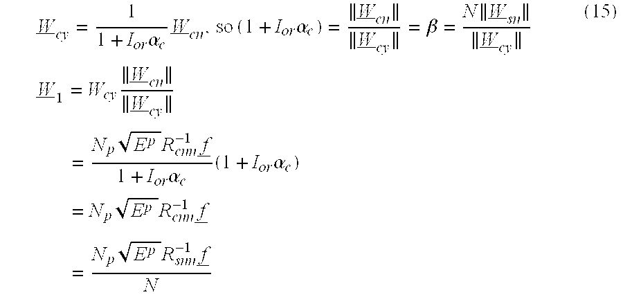
- In the above expression,
RX SNR estimator 34 eliminates β in the denominator of W cy. As shown above,RX SNR estimator 34 can compute W 1 from W sn where the difference is a processing gain scaling. New scaled channels at the output of the spatial 2-tap causalFIR Wiener filter 56 are as follows: - Traffic: y=W H Y=N p N{square root}{square root over (EpEd)}αc x+noise (N 1) (16)
- Pilot:z=W 1 H P=N e 2 E pαc+noise (N 2) (17)
- where N 1 and N2 are complex noise processes.
- Again, spatial projection Wiener filter spectral shaping by
RX SNR estimator 34 serves to fold the desired SNR into the signal amplitude, thereby transforming the classic SNR estimation into that of a signal amplitude estimation problem. SpatialProjection Wiener filter 56 serves to convert traffic Y and P to y and z, respectively, as follows: - y=Ax+N 1
- z=B+N 2,
- where
- A=N p N{square root}{square root over (EpEd)}αc (18)
- B=N p 2 E pαc (19)
- In this case, the following relationship holds:

- As a result,
RX SNR estimator 34 can determine the signal-to-noise ratio by estimating C in the presence of noise. The estimate of C may be accomplished more readily, however, by independent estimation of A and B. Note that:
- To solve the estimation problem, it is necessary to estimate A and B. Given the following post spatial Weiner filter scalar traffic and pilot channels:
- y i ′=Ax+N 1i
- z i ′=B+N 2i (21)
- y i=Real {y i′} and z i=Real {z i′}
-
RX SNR estimator 34 estimates the values of A and B and thus
- The basic estimator will treat the QPSK x as two independent BPSK channels, and therefore operates on I and Q separately. Letting y i=Real {yi′} and zi=Real {zi′}, note that A and B vary with time also because they involve fade.

- per finger and sum across fingers.
- To solve the problem within Maximum Likelihood Framework, letting z denote the pilot channel, and y denote the Wiener filter output traffic sequence, and 1(A, B|x) denote the conditional likelihood, it follows that:

- where σ 2=W 1 HRsnn W 1 is the power of the noise and K is the number of observation samples at the symbol rate. The unconditional log likelihood then can be represented, independent of x, as follows:

- where x is treated as BPSK. QPSK is treated as two independent BPSK channels. The following approximation is used to solve the problem:

- The approximate unconditional log likelihood can then be represented as:

- Optimizing the above equation (23) results in the (suboptimum) maximum likelihood estimates of A and B:

- where K represents the bits in the power control group.
- Having found  and {circumflex over (B)}, then: estimated

- From equation (21) above, y i=Real {yi′} and zi=Real {zi′}. In this case, approximation is in the first order. Higher order will improve performance, requiring σ2.
- FIG. 6 is a block diagram illustrating an exemplary
RX SNR estimator 34A in greater detail. FIG. 6 represents a BPSK conceptual example for purposes of illustration.RX SNR estimator 34A may be incorporated in a finger processor of a RAKE receiver in aWCD 14 as shown in FIG. 4. Accordingly,WCD 14 may include a RAKE receiver with multiple finger processors and, hence, multiple instances ofRX SNR estimator 34, i.e., one for each finger processor. As shown in FIG. 6,RX SNR estimator 34A includes a chiplevel computation unit 58, a finger front end (FFE)unit 60, anLMMSE unit 62, a spatial projection wiener filter (SPWF)unit 64, areal transform unit 66, atraffic summation unit 68, apilot summation unit 70, and anSNR calculation unit 72. - In the example of FIG. 6, chip
level computation unit 58 processes received signals y1 and y2 fromantennas FFE unit 60 processes received signals y1 and y2 to produce traffic and pilot symbol estimates Y and P, respectively.LMMSE unit 62 processes the chip level estimate {circumflex over (R)}cyy to formulate Wiener filter coefficients W 1. - There are essentially two choices in producing multiplath estimates. As a first example, we can estimate for the individual paths and then combined the results. Alternatively, we can combine the individual paths first and then produce an estimate for the combined results. Both approaches are contemplated herein. If each
antenna - W 1(k)=N p {square root}{square root over (Ep)} R cnn −1(k) f (k) (24)
- where, as indicated in equation (7),
- R cnn −1(k)=NR snn −1(k) k-th path correlation
- f(k) k-th path fade
- Upon computation of SPWF coefficients W 1 by
LMMSE unit 62, the resultingSPWF 64 for finger K output to traffic and pilot channels Y and P becomes: - y(k)=W 1 H(k) Y (k)=NN p {square root}{square root over (EpEd)}α c(k)+W 1 H(k) noise (k)
- z(k)=W 1 H(k) Y (k)=N p 2 E pαc(k)+ W 1 H(k) noise (k)
- where
- αc(k)=f H R cnn −1(k) f (k) is the k-finger fade weighted norm
- With further reference to FIG. 6,
SPWF 64 applies a spatial projection wiener filter function to traffic symbols Y and pilot symbols P according to the SPWF coefficient W 1 produced byLMMSE unit 62, and thereby produces filtered outputs yi′ and zi′. If y′ and z′ denote the SPWF output for all combined fingers in the RAKE receiver at the output ofSPWF 64, then:
- The resulting combined signal-to-noise ratio can be represented as:

- Combined (total fingers) SNR (26)
- If A and B denote the combined envelope of traffic and pilot channel y and z, then

- Accordingly, it can be seen that:

- =desired finger combined SNR
- We can now estimate A and B. This would represent the combining followed by the estimation architecture. Therefore, the same principle of SPWF output envelope estimation also holds for the multifinger case.
- Alternatively, assuming that the paths are more than 1.5 chip away from one another, they are statistically independent and joint ML estimation of A 1, A2, . . . AL results in marginal unconditional likelihoods,
- L(A k ,B k)=1n[E x ]{p(x,z|A k ,B, x)}
- where A k and Bk are finger k SPWF output noiseless envelopes. Solving the individual likelihood as in the single path results in:

- The above computation can be realized by
real transformation unit 66, andsummation units 
- as achieved by
SNR computation unit 72 in FIG. 6. Under correlated multipath interference, to avoid overestimation, a sum of squares can be used rather than a square of the sum for A as shown in FIG. 8. Note that this represents the approach by which the individual paths are estimated first, and then the result is combined. Alternatively, we can combine the paths first, and then produce an estimate for the combined result as shown in FIG. 7 for QPSK. - FIG. 7 is a block diagram illustrating another
RX SNR estimator 34B for incorporation inWCD 14 as shown in FIG. 4. In the example of FIG. 7, multiple paths are combined first, and then estimates are produced for the combined result.RX SNR estimator 34B conforms substantially toRX SNR estimator 34A of FIG. 6, but is configured for QPSK rather than BPSK. To that end,RX SNR estimator 34B further includes animaginary transformation unit 74 to produce an imaginary component of yi′, as well as an imaginarycomponent summation unit 76 to produce ÂQ. In this case,SNR computation unit 72 is modified to estimate Eb/Nt according the following expression:
- where  Q is produced by
imaginary transformation unit 74 andsummation unit 76. - FIG. 8 is a block diagram illustrating a multi-finger SNR estimator for a RAKE receiver in a
WCD 14. FIG. 8 illustrates an approach is which the SNR estimate is made prior to combining finger outputs. As an alternative, however, SNR estimation could be carried out following combination of the finger outputs, as shown in the example of FIG. 7. As shown in FIG. 8, the multi-finger SNR estimator includes a plurality of finger SNR processors 78 A-78 L for the L resolvable paths presented byantennas combiner 80 produces a combined receive diversity estimated SNR (Eb/Nt) according to the expression:
-
Power control processor 28 can use the combined SNR estimate to generate an appropriate power control command forbase station 12. - FIG. 9 is a flow diagram illustrating a technique for estimation of SNR using receive diversity. The SNR estimation technique may be implemented within
power control processor 28 and generally conforms to the computations described herein. In general, the technique may involve receiving spatial signal samples from a diversity antenna arrangement (82), generating traffic symbol estimates (84), and generating pilot symbol estimates (86). The technique further involves scaling the traffic and pilot symbol estimates using a spatial projection wiener filter function (88), and then estimating the SNR based on the scaled traffic and pilot symbol estimates (90). - FIG. 10 is a flow diagram illustrating the technique of FIG. 9 in greater detail. As shown in FIG. 10, the SNR estimation technique may involve receiving spatial signal samples from a diversity antenna arrangement ( 92), generating chip-level estimates based on the spatial samples (94), generating traffic symbol estimates (84), and generating pilot symbol estimates (86). In addition, the SNR estimation technique may involve computing a coefficient vector to formulate a spatial projection wiener filter function (100), and scaling the traffic and pilot symbol estimates using the spatial projection wiener filter function (102). Upon estimation of the SNR based on the scaled traffic and pilot symbol estimates (104), the technique may further involve the generation of a power control command (106).
- Although this disclosure has described the SNR estimation techniques in the context of receive diversity, similar techniques may be implemented without receive diversity. In some embodiments, for example, the techniques may involve generation of generating traffic and pilot symbol estimates for a wireless signal received via a single receive antenna, followed by scaling of traffic and pilot symbol estimates using a spatial projection wiener filter function as described herein. In this case, the spatial projection wiener filter function may be used for SNR estimation in single-antenna or receive diversity antenna arrangements.
- If any the techniques described herein, or portions of such techniques, are implemented in software, a computer-readable medium may store computer readable instructions, i.e., program code, that can be executed by a processor or DSP to carry out one of more of the techniques described above. For example, the computer readable medium may comprise random access memory (RAM), read-only memory (ROM), non-volatile random access memory (NVRAM), electrically erasable programmable read-only memory (EEPROM), flash memory, magnetic or optical media, or the like. Hence, the computer readable medium may comprise computer readable instructions that when executed in a WCD, cause the WCD to carry out one or more of the techniques described herein.
- Various embodiments have been described. These and other embodiments are within the scope of the following claims.
Claims (42)
Priority Applications (6)
| Application Number | Priority Date | Filing Date | Title |
|---|---|---|---|
| US10/448,815 US7366137B2 (en) | 2003-05-31 | 2003-05-31 | Signal-to-noise estimation in wireless communication devices with receive diversity |
| EP04776207A EP1629648A1 (en) | 2003-05-31 | 2004-05-28 | Signal-to-noise estimation in wireless communication devices with receive diversity |
| PCT/US2004/017162 WO2004112337A1 (en) | 2003-05-31 | 2004-05-28 | Signal-to-noise estimation in wireless communication devices with receive diversity |
| JP2006515046A JP2006526961A (en) | 2003-05-31 | 2004-05-28 | Signal-to-noise estimation in wireless communication devices using receive diversity |
| CA002525232A CA2525232A1 (en) | 2003-05-31 | 2004-05-28 | Signal-to-noise estimation in wireless communication devices with receive diversity |
| RU2005141564/09A RU2349034C2 (en) | 2003-05-31 | 2004-05-28 | Estimation of signal to noise relation in devices of wireless communication with reception separation |
Applications Claiming Priority (1)
| Application Number | Priority Date | Filing Date | Title |
|---|---|---|---|
| US10/448,815 US7366137B2 (en) | 2003-05-31 | 2003-05-31 | Signal-to-noise estimation in wireless communication devices with receive diversity |
Publications (2)
| Publication Number | Publication Date |
|---|---|
| US20040240419A1 true US20040240419A1 (en) | 2004-12-02 |
| US7366137B2 US7366137B2 (en) | 2008-04-29 |
Family
ID=33451592
Family Applications (1)
| Application Number | Title | Priority Date | Filing Date |
|---|---|---|---|
| US10/448,815 Expired - Fee Related US7366137B2 (en) | 2003-05-31 | 2003-05-31 | Signal-to-noise estimation in wireless communication devices with receive diversity |
Country Status (6)
| Country | Link |
|---|---|
| US (1) | US7366137B2 (en) |
| EP (1) | EP1629648A1 (en) |
| JP (1) | JP2006526961A (en) |
| CA (1) | CA2525232A1 (en) |
| RU (1) | RU2349034C2 (en) |
| WO (1) | WO2004112337A1 (en) |
Cited By (40)
| Publication number | Priority date | Publication date | Assignee | Title |
|---|---|---|---|---|
| EP1696503A1 (en) | 2005-02-28 | 2006-08-30 | Research In Motion Limited | Mobile wireless communication device with human interface diversity antenna and related methods |
| US20090074042A1 (en) * | 2007-09-17 | 2009-03-19 | Che-Li Lin | Scaling apparatus of a receiver |
| US20100080318A1 (en) * | 2007-01-16 | 2010-04-01 | Koninklijke Philips Electronics, N.V. | System and method for improved frequency estimation for high-speed communication |
| US8045512B2 (en) | 2005-10-27 | 2011-10-25 | Qualcomm Incorporated | Scalable frequency band operation in wireless communication systems |
| US8098568B2 (en) | 2000-09-13 | 2012-01-17 | Qualcomm Incorporated | Signaling method in an OFDM multiple access system |
| US8446892B2 (en) | 2005-03-16 | 2013-05-21 | Qualcomm Incorporated | Channel structures for a quasi-orthogonal multiple-access communication system |
| US8462859B2 (en) | 2005-06-01 | 2013-06-11 | Qualcomm Incorporated | Sphere decoding apparatus |
| US8477684B2 (en) | 2005-10-27 | 2013-07-02 | Qualcomm Incorporated | Acknowledgement of control messages in a wireless communication system |
| US8565194B2 (en) | 2005-10-27 | 2013-10-22 | Qualcomm Incorporated | Puncturing signaling channel for a wireless communication system |
| US8582509B2 (en) | 2005-10-27 | 2013-11-12 | Qualcomm Incorporated | Scalable frequency band operation in wireless communication systems |
| US8582548B2 (en) | 2005-11-18 | 2013-11-12 | Qualcomm Incorporated | Frequency division multiple access schemes for wireless communication |
| US8599945B2 (en) | 2005-06-16 | 2013-12-03 | Qualcomm Incorporated | Robust rank prediction for a MIMO system |
| US8611284B2 (en) | 2005-05-31 | 2013-12-17 | Qualcomm Incorporated | Use of supplemental assignments to decrement resources |
| US8644292B2 (en) | 2005-08-24 | 2014-02-04 | Qualcomm Incorporated | Varied transmission time intervals for wireless communication system |
| US8693405B2 (en) | 2005-10-27 | 2014-04-08 | Qualcomm Incorporated | SDMA resource management |
| US8831607B2 (en) | 2006-01-05 | 2014-09-09 | Qualcomm Incorporated | Reverse link other sector communication |
| US8879511B2 (en) | 2005-10-27 | 2014-11-04 | Qualcomm Incorporated | Assignment acknowledgement for a wireless communication system |
| US8885628B2 (en) | 2005-08-08 | 2014-11-11 | Qualcomm Incorporated | Code division multiplexing in a single-carrier frequency division multiple access system |
| US8917654B2 (en) | 2005-04-19 | 2014-12-23 | Qualcomm Incorporated | Frequency hopping design for single carrier FDMA systems |
| US9088384B2 (en) | 2005-10-27 | 2015-07-21 | Qualcomm Incorporated | Pilot symbol transmission in wireless communication systems |
| US9130810B2 (en) | 2000-09-13 | 2015-09-08 | Qualcomm Incorporated | OFDM communications methods and apparatus |
| US9136974B2 (en) | 2005-08-30 | 2015-09-15 | Qualcomm Incorporated | Precoding and SDMA support |
| US9137822B2 (en) | 2004-07-21 | 2015-09-15 | Qualcomm Incorporated | Efficient signaling over access channel |
| US9143305B2 (en) | 2005-03-17 | 2015-09-22 | Qualcomm Incorporated | Pilot signal transmission for an orthogonal frequency division wireless communication system |
| US9144060B2 (en) | 2005-10-27 | 2015-09-22 | Qualcomm Incorporated | Resource allocation for shared signaling channels |
| US9148256B2 (en) | 2004-07-21 | 2015-09-29 | Qualcomm Incorporated | Performance based rank prediction for MIMO design |
| US9154211B2 (en) | 2005-03-11 | 2015-10-06 | Qualcomm Incorporated | Systems and methods for beamforming feedback in multi antenna communication systems |
| US9172453B2 (en) | 2005-10-27 | 2015-10-27 | Qualcomm Incorporated | Method and apparatus for pre-coding frequency division duplexing system |
| US9179319B2 (en) | 2005-06-16 | 2015-11-03 | Qualcomm Incorporated | Adaptive sectorization in cellular systems |
| US9184870B2 (en) | 2005-04-01 | 2015-11-10 | Qualcomm Incorporated | Systems and methods for control channel signaling |
| US9210651B2 (en) | 2005-10-27 | 2015-12-08 | Qualcomm Incorporated | Method and apparatus for bootstraping information in a communication system |
| US9209956B2 (en) | 2005-08-22 | 2015-12-08 | Qualcomm Incorporated | Segment sensitive scheduling |
| US9225416B2 (en) | 2005-10-27 | 2015-12-29 | Qualcomm Incorporated | Varied signaling channels for a reverse link in a wireless communication system |
| US9225488B2 (en) | 2005-10-27 | 2015-12-29 | Qualcomm Incorporated | Shared signaling channel |
| US9246560B2 (en) | 2005-03-10 | 2016-01-26 | Qualcomm Incorporated | Systems and methods for beamforming and rate control in a multi-input multi-output communication systems |
| US9307544B2 (en) | 2005-04-19 | 2016-04-05 | Qualcomm Incorporated | Channel quality reporting for adaptive sectorization |
| US9461859B2 (en) | 2005-03-17 | 2016-10-04 | Qualcomm Incorporated | Pilot signal transmission for an orthogonal frequency division wireless communication system |
| US9520972B2 (en) * | 2005-03-17 | 2016-12-13 | Qualcomm Incorporated | Pilot signal transmission for an orthogonal frequency division wireless communication system |
| US20170142651A1 (en) * | 2015-03-04 | 2017-05-18 | Telefonaktiebolaget L M Ericsson (Publ) | Controlling Power Usage |
| US9660776B2 (en) | 2005-08-22 | 2017-05-23 | Qualcomm Incorporated | Method and apparatus for providing antenna diversity in a wireless communication system |
Families Citing this family (11)
| Publication number | Priority date | Publication date | Assignee | Title |
|---|---|---|---|---|
| EP1997247A2 (en) * | 2006-03-07 | 2008-12-03 | The Governors of the University of Alberta | Non-data-aided channel estimators for multipath and multiple antenna wireless systems |
| CN102104957B (en) | 2009-12-21 | 2013-10-09 | 华为技术有限公司 | Method and device for indicating multiple user-multiple input multiple output (MU-MIMO) mode |
| AU2011207101B2 (en) | 2010-01-19 | 2014-07-17 | Advanced Micro Devices, Inc. | Estimation of signal to noise ratio in receivers |
| US8676141B1 (en) * | 2010-10-15 | 2014-03-18 | Sprint Spectrum L.P. | Power control based on mobile receive diversity |
| AU2011325824B2 (en) | 2010-11-03 | 2015-07-16 | Linn-Mahler Holdings Inc. | Method and apparatus for generating a metric for use in one or more of lock detection, SNR estimation, and modulation classification |
| US9185614B2 (en) * | 2011-11-10 | 2015-11-10 | Qualcomm Incorporated | Computation of measurement metrics for wireless networks |
| CN105612792A (en) * | 2014-03-18 | 2016-05-25 | 华为技术有限公司 | Power control method and device |
| US9470033B1 (en) * | 2015-06-09 | 2016-10-18 | Ford Global Technologies, Llc | System and method for controlling vehicle access component |
| CN105096319B (en) * | 2015-09-10 | 2017-11-07 | 北京空间机电研究所 | A kind of in-orbit signal to noise ratio method of testing of satellite based on staring imaging |
| CN111257653B (en) * | 2020-01-16 | 2021-06-22 | 湘潭大学 | Electromagnetic radiation prediction method under underground pedestrian passageway scene |
| RU202395U1 (en) * | 2020-06-16 | 2021-02-16 | Общество с ограниченной ответственностью "Комбайновый завод "Ростсельмаш" | GRAIN LOSS CONTROL DEVICE FOR COARSE SEPARATOR |
Citations (10)
| Publication number | Priority date | Publication date | Assignee | Title |
|---|---|---|---|---|
| US5621723A (en) * | 1994-09-27 | 1997-04-15 | Gte Laboratories Incorporated | Power control in a CDMA network |
| US5991329A (en) * | 1995-06-30 | 1999-11-23 | Interdigital Technology Corporation | Automatic power control system for a code division multiple access (CDMA) communications system |
| US6075974A (en) * | 1996-11-20 | 2000-06-13 | Qualcomm Inc. | Method and apparatus for adjusting thresholds and measurements of received signals by anticipating power control commands yet to be executed |
| US6154659A (en) * | 1997-12-24 | 2000-11-28 | Nortel Networks Limited | Fast forward link power control in a code division multiple access system |
| US20020097782A1 (en) * | 1999-04-28 | 2002-07-25 | Kari Pajukoski | Method of forming channel estimate, and receiver |
| US6526031B1 (en) * | 2001-06-21 | 2003-02-25 | Motorola, Inc. | Forward power control determination in spread spectrum communications systems |
| US20030058962A1 (en) * | 2001-08-07 | 2003-03-27 | Baldwin Keith R. | Intelligent control system and method for compensation application in a wireless communications system |
| US6542483B1 (en) * | 2000-11-08 | 2003-04-01 | Motorola, Inc. | Method and an apparatus for Eb/Nt estimation for forward power control in spread spectrum communications systems |
| US6744749B2 (en) * | 2002-06-05 | 2004-06-01 | Qualcomm, Incorporated | Method and apparatus for pilot estimation using a wiener filter |
| US20040179496A1 (en) * | 2003-03-12 | 2004-09-16 | Farrokh Abrishamkar | Pilot estimation using prediction error method-switched filters |
Family Cites Families (2)
| Publication number | Priority date | Publication date | Assignee | Title |
|---|---|---|---|---|
| MY130820A (en) | 1998-12-16 | 2007-07-31 | Ericsson Telefon Ab L M | Channel estimation for a cdma system using pre-defined symbols in addition to pilot symbols |
| WO2002023840A1 (en) | 2000-09-15 | 2002-03-21 | Telefonaktiebolaget Lm Ericsson (Publ) | Pilot-assisted channel estimation with pilot interpolation |
-
2003
- 2003-05-31 US US10/448,815 patent/US7366137B2/en not_active Expired - Fee Related
-
2004
- 2004-05-28 WO PCT/US2004/017162 patent/WO2004112337A1/en active Application Filing
- 2004-05-28 CA CA002525232A patent/CA2525232A1/en not_active Abandoned
- 2004-05-28 JP JP2006515046A patent/JP2006526961A/en active Pending
- 2004-05-28 EP EP04776207A patent/EP1629648A1/en not_active Withdrawn
- 2004-05-28 RU RU2005141564/09A patent/RU2349034C2/en not_active IP Right Cessation
Patent Citations (11)
| Publication number | Priority date | Publication date | Assignee | Title |
|---|---|---|---|---|
| US5621723A (en) * | 1994-09-27 | 1997-04-15 | Gte Laboratories Incorporated | Power control in a CDMA network |
| US5991329A (en) * | 1995-06-30 | 1999-11-23 | Interdigital Technology Corporation | Automatic power control system for a code division multiple access (CDMA) communications system |
| US6075974A (en) * | 1996-11-20 | 2000-06-13 | Qualcomm Inc. | Method and apparatus for adjusting thresholds and measurements of received signals by anticipating power control commands yet to be executed |
| US6154659A (en) * | 1997-12-24 | 2000-11-28 | Nortel Networks Limited | Fast forward link power control in a code division multiple access system |
| US20020097782A1 (en) * | 1999-04-28 | 2002-07-25 | Kari Pajukoski | Method of forming channel estimate, and receiver |
| US6542483B1 (en) * | 2000-11-08 | 2003-04-01 | Motorola, Inc. | Method and an apparatus for Eb/Nt estimation for forward power control in spread spectrum communications systems |
| US6526031B1 (en) * | 2001-06-21 | 2003-02-25 | Motorola, Inc. | Forward power control determination in spread spectrum communications systems |
| US20030058962A1 (en) * | 2001-08-07 | 2003-03-27 | Baldwin Keith R. | Intelligent control system and method for compensation application in a wireless communications system |
| US6744749B2 (en) * | 2002-06-05 | 2004-06-01 | Qualcomm, Incorporated | Method and apparatus for pilot estimation using a wiener filter |
| US20040179496A1 (en) * | 2003-03-12 | 2004-09-16 | Farrokh Abrishamkar | Pilot estimation using prediction error method-switched filters |
| US7061882B2 (en) * | 2003-03-12 | 2006-06-13 | Qualcomm Incorporated | Pilot estimation using prediction error method-switched filters |
Cited By (61)
| Publication number | Priority date | Publication date | Assignee | Title |
|---|---|---|---|---|
| US9426012B2 (en) | 2000-09-13 | 2016-08-23 | Qualcomm Incorporated | Signaling method in an OFDM multiple access system |
| US9130810B2 (en) | 2000-09-13 | 2015-09-08 | Qualcomm Incorporated | OFDM communications methods and apparatus |
| US11032035B2 (en) | 2000-09-13 | 2021-06-08 | Qualcomm Incorporated | Signaling method in an OFDM multiple access system |
| US10313069B2 (en) | 2000-09-13 | 2019-06-04 | Qualcomm Incorporated | Signaling method in an OFDM multiple access system |
| US8098568B2 (en) | 2000-09-13 | 2012-01-17 | Qualcomm Incorporated | Signaling method in an OFDM multiple access system |
| US8098569B2 (en) | 2000-09-13 | 2012-01-17 | Qualcomm Incorporated | Signaling method in an OFDM multiple access system |
| US9137822B2 (en) | 2004-07-21 | 2015-09-15 | Qualcomm Incorporated | Efficient signaling over access channel |
| US10517114B2 (en) | 2004-07-21 | 2019-12-24 | Qualcomm Incorporated | Efficient signaling over access channel |
| US10849156B2 (en) | 2004-07-21 | 2020-11-24 | Qualcomm Incorporated | Efficient signaling over access channel |
| US10237892B2 (en) | 2004-07-21 | 2019-03-19 | Qualcomm Incorporated | Efficient signaling over access channel |
| US9148256B2 (en) | 2004-07-21 | 2015-09-29 | Qualcomm Incorporated | Performance based rank prediction for MIMO design |
| US10194463B2 (en) | 2004-07-21 | 2019-01-29 | Qualcomm Incorporated | Efficient signaling over access channel |
| US11039468B2 (en) | 2004-07-21 | 2021-06-15 | Qualcomm Incorporated | Efficient signaling over access channel |
| EP1696503A1 (en) | 2005-02-28 | 2006-08-30 | Research In Motion Limited | Mobile wireless communication device with human interface diversity antenna and related methods |
| US9246560B2 (en) | 2005-03-10 | 2016-01-26 | Qualcomm Incorporated | Systems and methods for beamforming and rate control in a multi-input multi-output communication systems |
| US9154211B2 (en) | 2005-03-11 | 2015-10-06 | Qualcomm Incorporated | Systems and methods for beamforming feedback in multi antenna communication systems |
| US8547951B2 (en) | 2005-03-16 | 2013-10-01 | Qualcomm Incorporated | Channel structures for a quasi-orthogonal multiple-access communication system |
| US8446892B2 (en) | 2005-03-16 | 2013-05-21 | Qualcomm Incorporated | Channel structures for a quasi-orthogonal multiple-access communication system |
| US9461859B2 (en) | 2005-03-17 | 2016-10-04 | Qualcomm Incorporated | Pilot signal transmission for an orthogonal frequency division wireless communication system |
| US9520972B2 (en) * | 2005-03-17 | 2016-12-13 | Qualcomm Incorporated | Pilot signal transmission for an orthogonal frequency division wireless communication system |
| US9143305B2 (en) | 2005-03-17 | 2015-09-22 | Qualcomm Incorporated | Pilot signal transmission for an orthogonal frequency division wireless communication system |
| US9184870B2 (en) | 2005-04-01 | 2015-11-10 | Qualcomm Incorporated | Systems and methods for control channel signaling |
| US9307544B2 (en) | 2005-04-19 | 2016-04-05 | Qualcomm Incorporated | Channel quality reporting for adaptive sectorization |
| US8917654B2 (en) | 2005-04-19 | 2014-12-23 | Qualcomm Incorporated | Frequency hopping design for single carrier FDMA systems |
| US9036538B2 (en) | 2005-04-19 | 2015-05-19 | Qualcomm Incorporated | Frequency hopping design for single carrier FDMA systems |
| US9408220B2 (en) | 2005-04-19 | 2016-08-02 | Qualcomm Incorporated | Channel quality reporting for adaptive sectorization |
| US8611284B2 (en) | 2005-05-31 | 2013-12-17 | Qualcomm Incorporated | Use of supplemental assignments to decrement resources |
| US8462859B2 (en) | 2005-06-01 | 2013-06-11 | Qualcomm Incorporated | Sphere decoding apparatus |
| US9179319B2 (en) | 2005-06-16 | 2015-11-03 | Qualcomm Incorporated | Adaptive sectorization in cellular systems |
| US8599945B2 (en) | 2005-06-16 | 2013-12-03 | Qualcomm Incorporated | Robust rank prediction for a MIMO system |
| US9693339B2 (en) | 2005-08-08 | 2017-06-27 | Qualcomm Incorporated | Code division multiplexing in a single-carrier frequency division multiple access system |
| US8885628B2 (en) | 2005-08-08 | 2014-11-11 | Qualcomm Incorporated | Code division multiplexing in a single-carrier frequency division multiple access system |
| US9660776B2 (en) | 2005-08-22 | 2017-05-23 | Qualcomm Incorporated | Method and apparatus for providing antenna diversity in a wireless communication system |
| US9240877B2 (en) | 2005-08-22 | 2016-01-19 | Qualcomm Incorporated | Segment sensitive scheduling |
| US9860033B2 (en) | 2005-08-22 | 2018-01-02 | Qualcomm Incorporated | Method and apparatus for antenna diversity in multi-input multi-output communication systems |
| US9246659B2 (en) | 2005-08-22 | 2016-01-26 | Qualcomm Incorporated | Segment sensitive scheduling |
| US9209956B2 (en) | 2005-08-22 | 2015-12-08 | Qualcomm Incorporated | Segment sensitive scheduling |
| US8787347B2 (en) | 2005-08-24 | 2014-07-22 | Qualcomm Incorporated | Varied transmission time intervals for wireless communication system |
| US8644292B2 (en) | 2005-08-24 | 2014-02-04 | Qualcomm Incorporated | Varied transmission time intervals for wireless communication system |
| US9136974B2 (en) | 2005-08-30 | 2015-09-15 | Qualcomm Incorporated | Precoding and SDMA support |
| US8477684B2 (en) | 2005-10-27 | 2013-07-02 | Qualcomm Incorporated | Acknowledgement of control messages in a wireless communication system |
| US8879511B2 (en) | 2005-10-27 | 2014-11-04 | Qualcomm Incorporated | Assignment acknowledgement for a wireless communication system |
| US9225416B2 (en) | 2005-10-27 | 2015-12-29 | Qualcomm Incorporated | Varied signaling channels for a reverse link in a wireless communication system |
| US9210651B2 (en) | 2005-10-27 | 2015-12-08 | Qualcomm Incorporated | Method and apparatus for bootstraping information in a communication system |
| US9144060B2 (en) | 2005-10-27 | 2015-09-22 | Qualcomm Incorporated | Resource allocation for shared signaling channels |
| US8045512B2 (en) | 2005-10-27 | 2011-10-25 | Qualcomm Incorporated | Scalable frequency band operation in wireless communication systems |
| US8842619B2 (en) | 2005-10-27 | 2014-09-23 | Qualcomm Incorporated | Scalable frequency band operation in wireless communication systems |
| US10805038B2 (en) | 2005-10-27 | 2020-10-13 | Qualcomm Incorporated | Puncturing signaling channel for a wireless communication system |
| US8582509B2 (en) | 2005-10-27 | 2013-11-12 | Qualcomm Incorporated | Scalable frequency band operation in wireless communication systems |
| US9088384B2 (en) | 2005-10-27 | 2015-07-21 | Qualcomm Incorporated | Pilot symbol transmission in wireless communication systems |
| US8693405B2 (en) | 2005-10-27 | 2014-04-08 | Qualcomm Incorporated | SDMA resource management |
| US9225488B2 (en) | 2005-10-27 | 2015-12-29 | Qualcomm Incorporated | Shared signaling channel |
| US9172453B2 (en) | 2005-10-27 | 2015-10-27 | Qualcomm Incorporated | Method and apparatus for pre-coding frequency division duplexing system |
| US8565194B2 (en) | 2005-10-27 | 2013-10-22 | Qualcomm Incorporated | Puncturing signaling channel for a wireless communication system |
| US8681764B2 (en) | 2005-11-18 | 2014-03-25 | Qualcomm Incorporated | Frequency division multiple access schemes for wireless communication |
| US8582548B2 (en) | 2005-11-18 | 2013-11-12 | Qualcomm Incorporated | Frequency division multiple access schemes for wireless communication |
| US8831607B2 (en) | 2006-01-05 | 2014-09-09 | Qualcomm Incorporated | Reverse link other sector communication |
| US20100080318A1 (en) * | 2007-01-16 | 2010-04-01 | Koninklijke Philips Electronics, N.V. | System and method for improved frequency estimation for high-speed communication |
| US8467476B2 (en) * | 2007-09-17 | 2013-06-18 | Mediatek Inc. | Scaling apparatus of a receiver |
| US20090074042A1 (en) * | 2007-09-17 | 2009-03-19 | Che-Li Lin | Scaling apparatus of a receiver |
| US20170142651A1 (en) * | 2015-03-04 | 2017-05-18 | Telefonaktiebolaget L M Ericsson (Publ) | Controlling Power Usage |
Also Published As
| Publication number | Publication date |
|---|---|
| WO2004112337A1 (en) | 2004-12-23 |
| CA2525232A1 (en) | 2004-12-23 |
| US7366137B2 (en) | 2008-04-29 |
| EP1629648A1 (en) | 2006-03-01 |
| RU2349034C2 (en) | 2009-03-10 |
| RU2005141564A (en) | 2006-05-27 |
| JP2006526961A (en) | 2006-11-24 |
Similar Documents
| Publication | Publication Date | Title |
|---|---|---|
| US7366137B2 (en) | Signal-to-noise estimation in wireless communication devices with receive diversity | |
| US7349379B2 (en) | Channel normalization | |
| CN100382437C (en) | Iterative soft interference cancellation and filtering for spectrally efficient high-speed transmission | |
| US7299017B2 (en) | Communication method, receiver and base station | |
| US6931050B1 (en) | Digital receivers and receiving methods that scale for relative strengths of traffic and pilot channels during soft handoff | |
| US20040185909A1 (en) | Linear transformation of symbols to at least partially compensate for correlation between antennas in space time block coded systems | |
| US6996385B2 (en) | Channel code decoding for the CDMA forward link | |
| AU725732B2 (en) | Method and apparatus for interference decorrelation in time and space | |
| US20030021246A1 (en) | Selection mechanism for signal combining methods | |
| US7236538B1 (en) | Method and apparatus for improving transmit antenna weight tracking using channel correlations in a wireless communication system | |
| US20030092447A1 (en) | Communications methods, apparatus and computer program products using gain multipliers | |
| US7180956B1 (en) | Method and apparatus for applying overlaid perturbation vectors for gradient feedback transmit antenna array adaptation | |
| US20070117527A1 (en) | Method and apparatus of multiple antenna receiver | |
| US20100067563A1 (en) | Method and system of communications | |
| US6856610B2 (en) | Wireless code division multiple access communications system with channel estimation using fingers with sub-chip spacing | |
| US7433416B1 (en) | Method and apparatus for generating transmit adaptive antenna weights with nulling using binary gradient feedback | |
| US7042928B2 (en) | Method and apparatus for pilot estimation using prediction error method | |
| US7184465B2 (en) | Signal processing method and apparatus for a spread spectrum radio communication receiver | |
| US7061882B2 (en) | Pilot estimation using prediction error method-switched filters | |
| US6744749B2 (en) | Method and apparatus for pilot estimation using a wiener filter | |
| US11025295B2 (en) | Optimizing MRC coefficients for RAKE receiver for increasing SNR | |
| US7418067B1 (en) | Processing diversity signals at a mobile device using phase adjustments | |
| US20040062217A1 (en) | Method and apparatus for pilot estimation using an adaptive prediction error method with a kalman filter and a gauss-newton algorithm | |
| US8018985B2 (en) | CDMA receivers for the golden code | |
| WO2005002067A2 (en) | Multi-carrier spread spectrum using non-linear modification of sub-carrier bands |
Legal Events
| Date | Code | Title | Description |
|---|---|---|---|
| AS | Assignment |
Owner name: QUALCOMM INCORPORATED, CALIFORNIA Free format text: ASSIGNMENT OF ASSIGNORS INTEREST;ASSIGNORS:ABRISHAMKAR, FARROKH;BANISTER, BRIAN;SIH, GILBERT C.;AND OTHERS;REEL/FRAME:014565/0541;SIGNING DATES FROM 20030912 TO 20030923 |
|
| AS | Assignment |
Owner name: QUALCOMM INCORPORATED, CALIFORNIA Free format text: ASSIGNMENT OF ASSIGNORS INTEREST;ASSIGNORS:ABRISHAMKAR, FARROKH;BANISTER, BRIAN;SIH, GILBERT CHRISTOPHER;AND OTHERS;REEL/FRAME:015987/0521;SIGNING DATES FROM 20050104 TO 20050317 |
|
| FPAY | Fee payment |
Year of fee payment: 4 |
|
| REMI | Maintenance fee reminder mailed | ||
| LAPS | Lapse for failure to pay maintenance fees | ||
| STCH | Information on status: patent discontinuation |
Free format text: PATENT EXPIRED DUE TO NONPAYMENT OF MAINTENANCE FEES UNDER 37 CFR 1.362 |
|
| FP | Expired due to failure to pay maintenance fee |
Effective date: 20160429 |