US20030194902A1 - Electrical connector assembly with a cable guiding member - Google Patents
Electrical connector assembly with a cable guiding member Download PDFInfo
- Publication number
- US20030194902A1 US20030194902A1 US10/337,740 US33774003A US2003194902A1 US 20030194902 A1 US20030194902 A1 US 20030194902A1 US 33774003 A US33774003 A US 33774003A US 2003194902 A1 US2003194902 A1 US 2003194902A1
- Authority
- US
- United States
- Prior art keywords
- hole
- cable
- casing parts
- guiding member
- electrical connector
- Prior art date
- Legal status (The legal status is an assumption and is not a legal conclusion. Google has not performed a legal analysis and makes no representation as to the accuracy of the status listed.)
- Granted
Links
Images


Classifications
-
- H—ELECTRICITY
- H01—ELECTRIC ELEMENTS
- H01R—ELECTRICALLY-CONDUCTIVE CONNECTIONS; STRUCTURAL ASSOCIATIONS OF A PLURALITY OF MUTUALLY-INSULATED ELECTRICAL CONNECTING ELEMENTS; COUPLING DEVICES; CURRENT COLLECTORS
- H01R13/00—Details of coupling devices of the kinds covered by groups H01R12/70 or H01R24/00 - H01R33/00
- H01R13/56—Means for preventing chafing or fracture of flexible leads at outlet from coupling part
- H01R13/567—Traverse cable outlet or wire connection
-
- H—ELECTRICITY
- H01—ELECTRIC ELEMENTS
- H01R—ELECTRICALLY-CONDUCTIVE CONNECTIONS; STRUCTURAL ASSOCIATIONS OF A PLURALITY OF MUTUALLY-INSULATED ELECTRICAL CONNECTING ELEMENTS; COUPLING DEVICES; CURRENT COLLECTORS
- H01R13/00—Details of coupling devices of the kinds covered by groups H01R12/70 or H01R24/00 - H01R33/00
- H01R13/58—Means for relieving strain on wire connection, e.g. cord grip, for avoiding loosening of connections between wires and terminals within a coupling device terminating a cable
- H01R13/5841—Means for relieving strain on wire connection, e.g. cord grip, for avoiding loosening of connections between wires and terminals within a coupling device terminating a cable allowing different orientations of the cable with respect to the coupling direction
Definitions
- the invention relates to a cable guiding member, more particularly to a cable guiding member that enables an electric cable terminated by an electrical connector member to be guided toward a desired direction.
- An electronic apparatus such as a computer, is generally provided with at least one of a universal serial bus (USB) connecting port, a PS/2 connecting port, a COM connecting port, an LPT connecting port, a terminal connecting port, and a digital-video interface (DVI) connecting port for connecting with corresponding interface connectors.
- USB universal serial bus
- PS/2 PS/2 connecting port
- COM COM connecting port
- LPT LPT connecting port
- terminal connecting port a terminal connecting port
- DVI digital-video interface
- the conventional power plug 5 includes a plurality of terminals 51 extending along a first direction, and an electric wire 52 connected electrically to the terminals 51 and extending along a second direction transverse to the first direction.
- FIG. 2 illustrates a conventional connector 9 for electrical connection between a power plug (not shown) and a socket (not shown).
- the conventional connector 9 has a plug portion 91 that is pivotable relative to the housing of the connector 9 .
- the abovementioned conventional connector 9 can only be used with a power plug, and is not adapted for use with the aforesaid interface connectors.
- the object of the present invention is to provide a cable guiding member that enables an electric cable terminated by an electrical connector member to be guided toward a desired direction.
- an electrical connector assembly comprises:
- a cable guiding member mounted on the end portion of the electric cable and formed with a first through hole having a first hole axis, a second through hole having a second hole axis, and a cable passage communicated with the first and second through holes, the second hole axis forming an angle with the first hole axis, the end portion of the electric cable extending into the cable passage via the first through hole and outwardly of the cable passage via the second through hole.
- a cable guiding member is adapted for use with an electric cable having an end portion terminated by an electrical connector member.
- the connector member includes a connector housing formed with a sleeve portion.
- the cable guiding member comprises:
- first and second casing parts each of which has first and second notches, the first notches of the first and second casing parts confining a first through hole with a first hole axis, the second notches of the first and second casing parts confining a second through hole with a second hole axis, the first and second casing parts further confining a cable passage communicated with the first and second through holes, the second hole axis forming an angle with the first hole axis, the first and second casing parts being adapted to permit the end portion of the electric cable to extend into the cable passage via the first through hole and outwardly of the cable passage via the second through hole, the first and second casing parts being adapted to permit the sleeve portion of the connector housing to extend into the cable passage via the first through hole;
- a positioning unit disposed in at least one of the first and second casing parts and adapted to engage the sleeve portion of the connector housing;
- a fastening unit for fastening together the first and second casing parts.
- FIG. 1 is a perspective view showing a combination of a conventional power plug and a socket
- FIG. 2 is a perspective view showing a conventional power connector
- FIG. 3 is an partly exploded perspective view showing the first preferred embodiment of an electrical connector assembly according to the present invention.
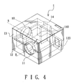
- FIG. 4 is a perspective view showing a cable guiding member of the first preferred embodiment
- FIG. 5 is a partly sectional, top schematic view showing the first preferred embodiment
- FIG. 6 is a partly sectional, top schematic view showing the second preferred embodiment of an electrical connector assembly according to the present invention.
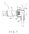
- FIG. 7 is a partly sectional, top schematic view showing the third preferred embodiment of an electrical connector assembly according to the present invention.
- the first preferred embodiment of an electrical connector assembly is shown to include an electric cable 20 , an electrical connector member 2 for signal transmission, and a cable guiding member 1 .
- the electric cable 20 which consists of a plurality of signal transmission lines (not shown), has an end portion 22 .
- the electrical connector member 2 terminates the end portion 22 of the electric cable 20 .
- the connector member may also be one of a USB connector, a PS/2 connector, a COM connector, an LPT connector and a digital video interface connector.
- the connector member 2 includes a connector housing 21 formed with a sleeve portion 210 .
- the sleeve portion 210 is formed with an annular engaging groove 211 .
- the cable guiding member 1 is mounted on the end portion 22 of the electric cable 20 , and is formed with a first through hole 10 having a first hole axis (A), a second through hole having a second hole (B), and a cable passage communicated with the first and second through holes 10 , 11 .
- the second hole axis (B) forms an angle ( ⁇ ) with the first hole axis (A).
- the angle ( ⁇ ) is equal to 90 degrees, i.e., the second hole axis (B) is transverse to the first hole axis (A), as best shown in FIG. 4.
- the end portion 22 of the electric cable 20 extends into the cable passage via the first through hole 10 and outwardly of the cable passage via the second through hole 11 .
- the cable guiding member 1 includes first and second casing parts 12 , 13 .
- the first casing part 12 has first and second notches 121 , 122 .
- the second casing part 13 has first and second notches 131 , 132 .
- the first notches 121 , 131 of the first and second casing parts 12 , 13 confine the first through hole 10 .
- the second notches 122 , 132 of the first and second casing parts 12 , 13 confine the second through hole 11 .
- the cable guiding member 1 may be formed with more than one second through hole 11 so as to provide various choices of the angle ( ⁇ ).
- the sleeve portion 210 of the connector housing 21 extends into the cable passage via the first through hole 10 .
- the first notch 121 of the first casing part 12 is formed with an engaging edge 1210 .
- the second notch 131 of the second casing part 13 is formed with an engaging edge 1310 .
- Each of the engaging edges 1210 , 1310 engages the engaging groove 211 in the sleeve portion 210 of the connector housing 21 to secure the connector member 2 to the cable guising member 1 .
- the cable guiding member 1 further includes a fastening unit for fastening together the first and second casing parts 12 , 13 .
- the fastening unit includes a resilient lug 133 formed on the second casing part 13 , and a projecting block 123 formed on the first casing part 12 .
- the lug 133 is formed with an engaging hole 1330 that engages the projecting block 123 to fasten releasably the first and second casing parts 12 , 13 to each other. It is noted that the first and second casing parts 12 , 13 can also be fastened together with the use of screws.
- the cable guiding member 1 further includes a positioning unit disposed therein for engaging the sleeve portion 210 of the connector housing 21 .
- the positioning unit includes a baffle unit that abuts against a distal end 212 of the sleeve portion 210 .
- the baffle unit includes two pairs of baffle plates 14 that are formed integrally with the first and second casing parts 12 , 13 .
- the baffle plates 14 confine an opening 140 (see FIG. 4) to permit the end portion 22 of the electric cable 20 to extend therethrough.
- FIG. 6 illustrates the second preferred embodiment of an electrical connector assembly according to the present invention, which is a modification of the first preferred embodiment.
- the electrical connector assembly further includes a flexible support tube 15 that is disposed around the end portion 22 of the electric cable 20 , outwardly of the cable passage, and adjacent to the second through hole 11 of the cable guiding member 1 ′.
- the positioning unit additionally includes a baffle block 140 disposed in the cable guiding member 1 ′ adjacent to the second through hole 11 .
- FIG. 7 illustrates the third preferred embodiment of an electrical connector assembly according to the invention, which is a modification of the first preferred embodiment.
- the sleeve portion 210 ′ of the connector housing 21 ′ has a knurled outer surface 2100 .
- the positioning unit includes a positioning plate 14 ′ having a teethed surface 141 for engaging the knurled outer surface 2100 of the sleeve portion 210 ′.
- the electrical connector assembly further includes a support tube 124 that is formed integrally with the cable guiding member 1 ′′.
Abstract
An electrical connector assembly includes an electric cable, and an electrical connector member for signal transmission. The connector member terminates an end portion of the electric cable. A cable guiding member is mounted on the end portion of the electric cable, and is formed with a first through hole having a first hole axis, a second through hole having a second hole axis, and a cable passage communicated with the first and second through holes. The second hole axis forms an angle with the first hole axis. The end portion of the electric cable extends into the cable passage via the first through hole and outwardly of the cable passage via the second through hole.
Description
- 1. Field of the Invention
- The invention relates to a cable guiding member, more particularly to a cable guiding member that enables an electric cable terminated by an electrical connector member to be guided toward a desired direction.
- 2. Description of the Related Art
- An electronic apparatus, such as a computer, is generally provided with at least one of a universal serial bus (USB) connecting port, a PS/2 connecting port, a COM connecting port, an LPT connecting port, a terminal connecting port, and a digital-video interface (DVI) connecting port for connecting with corresponding interface connectors. Since each of the above interface connectors is formed with a specific orientation, cable entanglement usually occurs at the back of the computer when a number of the interface connectors are connected to their corresponding connecting ports. FIG. 1 illustrates a
conventional power plug 5 that is inserted into asocket 6. Theconventional power plug 5 includes a plurality ofterminals 51 extending along a first direction, and anelectric wire 52 connected electrically to theterminals 51 and extending along a second direction transverse to the first direction. FIG. 2 illustrates a conventional connector 9 for electrical connection between a power plug (not shown) and a socket (not shown). The conventional connector 9 has aplug portion 91 that is pivotable relative to the housing of the connector 9. However, the abovementioned conventional connector 9 can only be used with a power plug, and is not adapted for use with the aforesaid interface connectors. - Therefore, the object of the present invention is to provide a cable guiding member that enables an electric cable terminated by an electrical connector member to be guided toward a desired direction.
- According to one aspect of the present invention, an electrical connector assembly comprises:
- an electric cable having an end portion;
- an electrical connector member for signal transmission, the connector member terminating the end portion of the electric cable; and
- a cable guiding member mounted on the end portion of the electric cable and formed with a first through hole having a first hole axis, a second through hole having a second hole axis, and a cable passage communicated with the first and second through holes, the second hole axis forming an angle with the first hole axis, the end portion of the electric cable extending into the cable passage via the first through hole and outwardly of the cable passage via the second through hole.
- According to another aspect of the present invention, a cable guiding member is adapted for use with an electric cable having an end portion terminated by an electrical connector member. The connector member includes a connector housing formed with a sleeve portion. The cable guiding member comprises:
- first and second casing parts, each of which has first and second notches, the first notches of the first and second casing parts confining a first through hole with a first hole axis, the second notches of the first and second casing parts confining a second through hole with a second hole axis, the first and second casing parts further confining a cable passage communicated with the first and second through holes, the second hole axis forming an angle with the first hole axis, the first and second casing parts being adapted to permit the end portion of the electric cable to extend into the cable passage via the first through hole and outwardly of the cable passage via the second through hole, the first and second casing parts being adapted to permit the sleeve portion of the connector housing to extend into the cable passage via the first through hole;
- a positioning unit disposed in at least one of the first and second casing parts and adapted to engage the sleeve portion of the connector housing; and
- a fastening unit for fastening together the first and second casing parts.
- Other features and advantages of the present invention will become apparent in the following detailed description of the preferred embodiments with reference to the accompanying drawings, of which:
- FIG. 1 is a perspective view showing a combination of a conventional power plug and a socket;
- FIG. 2 is a perspective view showing a conventional power connector;
- FIG. 3 is an partly exploded perspective view showing the first preferred embodiment of an electrical connector assembly according to the present invention;
- FIG. 4 is a perspective view showing a cable guiding member of the first preferred embodiment;
- FIG. 5 is a partly sectional, top schematic view showing the first preferred embodiment;
- FIG. 6 is a partly sectional, top schematic view showing the second preferred embodiment of an electrical connector assembly according to the present invention; and
- FIG. 7 is a partly sectional, top schematic view showing the third preferred embodiment of an electrical connector assembly according to the present invention.
- Before the present invention is described in greater detail, it should be noted that like elements are denoted by the same reference numerals throughout the disclosure.
- Referring to FIGS. 3 to 5, the first preferred embodiment of an electrical connector assembly according to the present invention is shown to include an
electric cable 20, anelectrical connector member 2 for signal transmission, and acable guiding member 1. - The
electric cable 20, which consists of a plurality of signal transmission lines (not shown), has anend portion 22. - The
electrical connector member 2, such as a USB connector, terminates theend portion 22 of theelectric cable 20. The connector member may also be one of a USB connector, a PS/2 connector, a COM connector, an LPT connector and a digital video interface connector. In this embodiment, theconnector member 2 includes aconnector housing 21 formed with asleeve portion 210. Thesleeve portion 210 is formed with an annularengaging groove 211. - The
cable guiding member 1 is mounted on theend portion 22 of theelectric cable 20, and is formed with a first throughhole 10 having a first hole axis (A), a second through hole having a second hole (B), and a cable passage communicated with the first and second throughholes end portion 22 of theelectric cable 20 extends into the cable passage via the first throughhole 10 and outwardly of the cable passage via the second throughhole 11. In this embodiment, thecable guiding member 1 includes first andsecond casing parts first casing part 12 has first andsecond notches second casing part 13 has first andsecond notches first notches second casing parts hole 10. Thesecond notches second casing parts hole 11. It is noted that thecable guiding member 1 may be formed with more than one second throughhole 11 so as to provide various choices of the angle (θ). Thesleeve portion 210 of theconnector housing 21 extends into the cable passage via the first throughhole 10. Thefirst notch 121 of thefirst casing part 12 is formed with anengaging edge 1210. Thesecond notch 131 of thesecond casing part 13 is formed with anengaging edge 1310. Each of theengaging edges engaging groove 211 in thesleeve portion 210 of theconnector housing 21 to secure theconnector member 2 to the cable guisingmember 1. - The
cable guiding member 1 further includes a fastening unit for fastening together the first andsecond casing parts resilient lug 133 formed on thesecond casing part 13, and aprojecting block 123 formed on thefirst casing part 12. Thelug 133 is formed with anengaging hole 1330 that engages theprojecting block 123 to fasten releasably the first andsecond casing parts second casing parts - The
cable guiding member 1 further includes a positioning unit disposed therein for engaging thesleeve portion 210 of theconnector housing 21. In this embodiment, the positioning unit includes a baffle unit that abuts against adistal end 212 of thesleeve portion 210. The baffle unit includes two pairs ofbaffle plates 14 that are formed integrally with the first andsecond casing parts baffle plates 14 confine an opening 140 (see FIG. 4) to permit theend portion 22 of theelectric cable 20 to extend therethrough. - FIG. 6 illustrates the second preferred embodiment of an electrical connector assembly according to the present invention, which is a modification of the first preferred embodiment. Unlike the previous embodiment, the electrical connector assembly further includes a
flexible support tube 15 that is disposed around theend portion 22 of theelectric cable 20, outwardly of the cable passage, and adjacent to the second throughhole 11 of thecable guiding member 1′. Furthermore, in this embodiment, the positioning unit additionally includes abaffle block 140 disposed in thecable guiding member 1′ adjacent to the second throughhole 11. - FIG. 7 illustrates the third preferred embodiment of an electrical connector assembly according to the invention, which is a modification of the first preferred embodiment. Unlike the first preferred embodiment, the
sleeve portion 210′ of theconnector housing 21′ has a knurledouter surface 2100. Moreover, the positioning unit includes apositioning plate 14′ having a teethedsurface 141 for engaging the knurledouter surface 2100 of thesleeve portion 210′. Furthermore, the electrical connector assembly further includes asupport tube 124 that is formed integrally with thecable guiding member 1″. - To sum up, due to the presence of the cable guiding member, the electric cable can be guided toward a desired direction. The object of the invention is thus met.
- While the present invention has been described in connection with what is considered the most practical and preferred embodiments, it is understood that this invention is not limited to the disclosed embodiments but is intended to cover various arrangements included within the spirit and scope of the broadest interpretation so as to encompass all such modifications and equivalent arrangements.
Claims (18)
1. An electrical connector assembly comprising:
an electric cable having an end portion;
an electrical connector member for signal transmission, said connector member terminating said end portion of said electric cable; and
a cable guiding member mounted on said end portion of said electric cable and formed with a first through hole having a first hole axis, a second through hole having a second hole axis, and a cable passage communicated with said first and second through holes, said second hole axis forming an angle with said first hole axis, said end portion of said electric cable extending into said cable passage via said first through hole and outwardly of said cable passage via said second through hole.
2. The electrical connector assembly as claimed in claim 1 , wherein said cable guiding member includes first and second casing parts, each of which has first and second notches, said first notches of said first and second casing parts confining said first through hole, said second notches of said first and second casing parts confining said second through hole.
3. The electrical connector assembly as claimed in claim 2 , wherein said cable guiding member further includes a fastening unit for fastening together said first and second casing parts.
4. The electrical connector assembly as claimed in claim 3 , wherein said fastening unit includes a resilient lug formed on one of said first and second casing parts, and a projecting block formed on the other one of said first and second casing parts, said lug engaging said projecting block to fasten releasably said first and second casing parts to each other.
5. The electrical connector assembly as claimed in claim 2 , wherein said connector member includes a connector housing formed with a sleeve portion that extends into said cable passage via said first through hole, said sleeve portion being formed with an annular engaging groove, each of said first notches of said first and second casing parts being formed with an inwardly extending engaging edge that engages said engaging groove to secure said connector member to said cable guiding member.
6. The electrical connector assembly as claimed in claim 2 , wherein said connector member includes a connector housing formed with a sleeve portion that extends into said cable passage via said first through hole, said cable guiding member further including a positioning unit disposed therein for engaging said sleeve portion of said connector housing.
7. The electrical connector assembly as claimed in claim 6 , wherein said positioning unit includes a baffle unit that abuts against a distal end of said sleeve portion and that is formed with an opening to permit said end portion of said electric cable to extend therethrough.
8. The electric connector assembly as claimed in claim 6 , wherein said sleeve portion has a knurled outer surface, said positioning unit including a positioning plate having a teethed surface for engaging said knurled outer surface of said sleeve portion.
9. The electrical connector assembly as claimed in claim 1 , further comprising a support tube disposed around said end portion of said electric cable, outwardly of said cable passage, and adjacent to said second through hole of said cable guiding member.
10. The electrical connector assembly as claimed in claim 9 , wherein said support tube is formed integrally with said cable guiding member.
11. The electrical connector assembly as claimed in claim 1 , wherein said electrical connector member is one of a universal serial bus connector, a PS/2 connector, a COM connector, an LPT connector and a digital video interface connector.
12. The electrical connector assembly as claimed in claim 1 , wherein said second hole axis is transverse to said first hole axis.
13. A cable guiding member for an electric cable having an end portion terminated by an electrical connector member, the connector member including a connector housing formed with a sleeve portion, said cable guiding member comprising:
first and second casing parts, each of which has first and second notches, said first notches of said first and second casing parts confining a first through hole with a first hole axis, said second notches of said first and second casing parts confining a second through hole with a second hole axis, said first and second casing parts further confining a cable passage communicated with said first and second through holes, said second hole axis forming an angle with said first hole axis, said first and second casing parts being adapted to permit the end portion of the electric cable to extend into said cable passage via said first through hole and outwardly of said cable passage via said second through hole, said first and second casing parts being adapted to permit the sleeve portion of the connector housing to extend into said cable passage via said first through hole;
a positioning unit disposed in at least one of said first and second casing parts and adapted to engage the sleeve portion of the connector housing; and
a fastening unit for fastening together said first and second casing parts.
14. The cable guiding member as claimed in claim 13 , wherein said fastening unit includes a resilient lug formed on one of said first and second casing parts, and a projecting block formed on the other one of said first and second casing parts, said lug engaging said projecting block to fasten releasably said first and second casing parts to each other.
15. The cable guiding member as claimed in claim 13 , wherein said positioning unit includes a baffle unit that is adapted to abut against a distal end of the sleeve portion and that is formed with an opening adapted to permit the end portion of the electric cable to extend therethrough.
16. The cable guiding member as claimed in claim 13 , wherein said positioning unit includes a positioning plate having a teethed surface adapted to engage the sleeve portion.
17. The cable guiding member as claimed in claim 13 , further comprising a support tube adapted to be disposed around the end portion of the electric cable, outwardly of said cable passage, and adjacent to said second through hole of said first and second casing parts.
18. The cable guiding member as claimed in claim 13 , wherein said second hole axis is transverse to said first hole axis.
Applications Claiming Priority (2)
| Application Number | Priority Date | Filing Date | Title |
|---|---|---|---|
| TW091205051U TW568406U (en) | 2002-04-16 | 2002-04-16 | Bending and folding fixer of electrical wire |
| TW091205051 | 2002-04-16 |
Publications (2)
| Publication Number | Publication Date |
|---|---|
| US20030194902A1 true US20030194902A1 (en) | 2003-10-16 |
| US6948969B2 US6948969B2 (en) | 2005-09-27 |
Family
ID=28789009
Family Applications (1)
| Application Number | Title | Priority Date | Filing Date |
|---|---|---|---|
| US10/337,740 Expired - Fee Related US6948969B2 (en) | 2002-04-16 | 2003-01-07 | Electrical connector assembly with a cable guiding member |
Country Status (2)
| Country | Link |
|---|---|
| US (1) | US6948969B2 (en) |
| TW (1) | TW568406U (en) |
Cited By (15)
| Publication number | Priority date | Publication date | Assignee | Title |
|---|---|---|---|---|
| FR2872961A1 (en) * | 2004-07-09 | 2006-01-13 | Valeo Vision Sa | END CONNECTOR OF ELECTRICAL BEAM |
| USD607829S1 (en) | 2007-11-26 | 2010-01-12 | Ds Engineering, Llc | Ringed, compressed coaxial cable F-connector with tactile surfaces |
| USD607826S1 (en) | 2007-11-15 | 2010-01-12 | Ds Engineering, Llc | Non-compressed coaxial cable F-connector with tactile surfaces |
| USD607830S1 (en) | 2007-11-26 | 2010-01-12 | Ds Engineering, Llc | Ringed, non-composed coaxial cable F-connector with tactile surfaces |
| USD607827S1 (en) | 2007-11-15 | 2010-01-12 | Ds Engineering, Llc | Compressed coaxial cable F-connector with tactile surfaces |
| USD607828S1 (en) | 2007-11-19 | 2010-01-12 | Ds Engineering, Llc | Ringed compressed coaxial cable F-connector |
| USD608294S1 (en) | 2007-11-19 | 2010-01-19 | Ds Engineering, Llc | Ringed non-compressed coaxial cable F-connector |
| US7841896B2 (en) | 2007-12-17 | 2010-11-30 | Ds Engineering, Llc | Sealed compression type coaxial cable F-connectors |
| US8371874B2 (en) | 2007-12-17 | 2013-02-12 | Ds Engineering, Llc | Compression type coaxial cable F-connectors with traveling seal and barbless post |
| US8834200B2 (en) | 2007-12-17 | 2014-09-16 | Perfectvision Manufacturing, Inc. | Compression type coaxial F-connector with traveling seal and grooved post |
| US9190773B2 (en) | 2011-12-27 | 2015-11-17 | Perfectvision Manufacturing, Inc. | Socketed nut coaxial connectors with radial grounding systems for enhanced continuity |
| US9362634B2 (en) | 2011-12-27 | 2016-06-07 | Perfectvision Manufacturing, Inc. | Enhanced continuity connector |
| US9564695B2 (en) | 2015-02-24 | 2017-02-07 | Perfectvision Manufacturing, Inc. | Torque sleeve for use with coaxial cable connector |
| US9908737B2 (en) | 2011-10-07 | 2018-03-06 | Perfectvision Manufacturing, Inc. | Cable reel and reel carrying caddy |
| US11319142B2 (en) | 2010-10-19 | 2022-05-03 | Ppc Broadband, Inc. | Cable carrying case |
Families Citing this family (1)
| Publication number | Priority date | Publication date | Assignee | Title |
|---|---|---|---|---|
| US11158987B2 (en) | 2020-01-06 | 2021-10-26 | International Business Machines Corporation | Multidirectional linecord |
Citations (8)
| Publication number | Priority date | Publication date | Assignee | Title |
|---|---|---|---|---|
| US4029896A (en) * | 1975-10-22 | 1977-06-14 | Electro-Therm, Inc. | Terminal housing for an electrical resistance heater |
| US4101189A (en) * | 1977-06-01 | 1978-07-18 | Amp Incorporated | Discrete wire interconnections for connector blocks |
| US4195194A (en) * | 1978-05-22 | 1980-03-25 | Amp Incorporated | Junction box |
| US4869686A (en) * | 1988-03-30 | 1989-09-26 | Molex Incorporated | Right angle electrical connector |
| US4921454A (en) * | 1989-06-20 | 1990-05-01 | Amp Incorporated | Cluster block assembly |
| US5211706A (en) * | 1992-06-09 | 1993-05-18 | Molex Incorporated | Strain relief shell for an electrical connector |
| US5731546A (en) * | 1996-03-15 | 1998-03-24 | Molex Incorporated | Telecommunications cable management tray with a row of arcuate cable guide walls |
| US6065075A (en) * | 1998-04-16 | 2000-05-16 | Sony Corporation | I/O port signal conversion apparatus and method |
-
2002
- 2002-04-16 TW TW091205051U patent/TW568406U/en not_active IP Right Cessation
-
2003
- 2003-01-07 US US10/337,740 patent/US6948969B2/en not_active Expired - Fee Related
Patent Citations (8)
| Publication number | Priority date | Publication date | Assignee | Title |
|---|---|---|---|---|
| US4029896A (en) * | 1975-10-22 | 1977-06-14 | Electro-Therm, Inc. | Terminal housing for an electrical resistance heater |
| US4101189A (en) * | 1977-06-01 | 1978-07-18 | Amp Incorporated | Discrete wire interconnections for connector blocks |
| US4195194A (en) * | 1978-05-22 | 1980-03-25 | Amp Incorporated | Junction box |
| US4869686A (en) * | 1988-03-30 | 1989-09-26 | Molex Incorporated | Right angle electrical connector |
| US4921454A (en) * | 1989-06-20 | 1990-05-01 | Amp Incorporated | Cluster block assembly |
| US5211706A (en) * | 1992-06-09 | 1993-05-18 | Molex Incorporated | Strain relief shell for an electrical connector |
| US5731546A (en) * | 1996-03-15 | 1998-03-24 | Molex Incorporated | Telecommunications cable management tray with a row of arcuate cable guide walls |
| US6065075A (en) * | 1998-04-16 | 2000-05-16 | Sony Corporation | I/O port signal conversion apparatus and method |
Cited By (17)
| Publication number | Priority date | Publication date | Assignee | Title |
|---|---|---|---|---|
| US20060099851A1 (en) * | 2004-07-09 | 2006-05-11 | Marc Duarte | Wiring harness end connector |
| US7465196B2 (en) | 2004-07-09 | 2008-12-16 | Valeo Vision | Wiring harness end connector |
| FR2872961A1 (en) * | 2004-07-09 | 2006-01-13 | Valeo Vision Sa | END CONNECTOR OF ELECTRICAL BEAM |
| USD607827S1 (en) | 2007-11-15 | 2010-01-12 | Ds Engineering, Llc | Compressed coaxial cable F-connector with tactile surfaces |
| USD607826S1 (en) | 2007-11-15 | 2010-01-12 | Ds Engineering, Llc | Non-compressed coaxial cable F-connector with tactile surfaces |
| USD608294S1 (en) | 2007-11-19 | 2010-01-19 | Ds Engineering, Llc | Ringed non-compressed coaxial cable F-connector |
| USD607828S1 (en) | 2007-11-19 | 2010-01-12 | Ds Engineering, Llc | Ringed compressed coaxial cable F-connector |
| USD607830S1 (en) | 2007-11-26 | 2010-01-12 | Ds Engineering, Llc | Ringed, non-composed coaxial cable F-connector with tactile surfaces |
| USD607829S1 (en) | 2007-11-26 | 2010-01-12 | Ds Engineering, Llc | Ringed, compressed coaxial cable F-connector with tactile surfaces |
| US7841896B2 (en) | 2007-12-17 | 2010-11-30 | Ds Engineering, Llc | Sealed compression type coaxial cable F-connectors |
| US8371874B2 (en) | 2007-12-17 | 2013-02-12 | Ds Engineering, Llc | Compression type coaxial cable F-connectors with traveling seal and barbless post |
| US8834200B2 (en) | 2007-12-17 | 2014-09-16 | Perfectvision Manufacturing, Inc. | Compression type coaxial F-connector with traveling seal and grooved post |
| US11319142B2 (en) | 2010-10-19 | 2022-05-03 | Ppc Broadband, Inc. | Cable carrying case |
| US9908737B2 (en) | 2011-10-07 | 2018-03-06 | Perfectvision Manufacturing, Inc. | Cable reel and reel carrying caddy |
| US9190773B2 (en) | 2011-12-27 | 2015-11-17 | Perfectvision Manufacturing, Inc. | Socketed nut coaxial connectors with radial grounding systems for enhanced continuity |
| US9362634B2 (en) | 2011-12-27 | 2016-06-07 | Perfectvision Manufacturing, Inc. | Enhanced continuity connector |
| US9564695B2 (en) | 2015-02-24 | 2017-02-07 | Perfectvision Manufacturing, Inc. | Torque sleeve for use with coaxial cable connector |
Also Published As
| Publication number | Publication date |
|---|---|
| US6948969B2 (en) | 2005-09-27 |
| TW568406U (en) | 2003-12-21 |
Similar Documents
| Publication | Publication Date | Title |
|---|---|---|
| US6948969B2 (en) | Electrical connector assembly with a cable guiding member | |
| US7128617B2 (en) | Electrical socket assembly and plug connector coupled thereto | |
| US7497738B2 (en) | Electrical connector interacting between two different interfaces | |
| US7059892B1 (en) | Electrical connector and backshell | |
| CN104362450B (en) | Plug connector with bidirectional plugging function | |
| US7537488B2 (en) | Communication cable connector and communication cable | |
| US6851960B2 (en) | AC adapter connector assembly | |
| US6309255B1 (en) | Electrical connector having power contacts for providing high electrical power | |
| TWI523349B (en) | Electrical connector having contact modules | |
| US6830483B1 (en) | Cable assembly with power adapter | |
| US6431906B1 (en) | Modular connectors with detachable line status indicators | |
| US6024588A (en) | Multi-socket computer adapter having a reversible plug | |
| US20100009574A1 (en) | Rotatable electrical interconnection device | |
| US7766696B2 (en) | Coaxial cable connector assembly | |
| US6383023B1 (en) | Electrical connector with power contacts positioned at lateral ends without increasing dimension thereof | |
| CN111384637A (en) | Wire clamping device and electric plug connector with same | |
| US20100029096A1 (en) | Rotatable electrical interconnection device | |
| US6494744B1 (en) | Connector assembly | |
| US20100093219A1 (en) | Cable assembly with grounding pieces | |
| US20010027037A1 (en) | Compact electrical adapter for mounting to a panel connector of a computer | |
| US20080305687A1 (en) | Electrical connector assembly | |
| US6296521B1 (en) | Electrical connector with power contacts positioned at lateral ends without increasing dimension thereof | |
| US11251562B2 (en) | Electrical power unit for a work surface | |
| US6890200B1 (en) | Floatable panel mount cable assembly | |
| CN111384636A (en) | Electrical plug connector and wire clamping device on electrical plug connector |
Legal Events
| Date | Code | Title | Description |
|---|---|---|---|
| FEPP | Fee payment procedure |
Free format text: PAYOR NUMBER ASSIGNED (ORIGINAL EVENT CODE: ASPN); ENTITY STATUS OF PATENT OWNER: SMALL ENTITY |
|
| REMI | Maintenance fee reminder mailed | ||
| LAPS | Lapse for failure to pay maintenance fees | ||
| STCH | Information on status: patent discontinuation |
Free format text: PATENT EXPIRED DUE TO NONPAYMENT OF MAINTENANCE FEES UNDER 37 CFR 1.362 |
|
| FP | Lapsed due to failure to pay maintenance fee |
Effective date: 20090927 |