US20030194225A1 - Rotatable plug assembly including an extra outlet - Google Patents
Rotatable plug assembly including an extra outlet Download PDFInfo
- Publication number
- US20030194225A1 US20030194225A1 US10/359,097 US35909703A US2003194225A1 US 20030194225 A1 US20030194225 A1 US 20030194225A1 US 35909703 A US35909703 A US 35909703A US 2003194225 A1 US2003194225 A1 US 2003194225A1
- Authority
- US
- United States
- Prior art keywords
- plug assembly
- plug
- housing
- appliance
- outlet
- Prior art date
- Legal status (The legal status is an assumption and is not a legal conclusion. Google has not performed a legal analysis and makes no representation as to the accuracy of the status listed.)
- Granted
Links
Images


Classifications
-
- A—HUMAN NECESSITIES
- A61—MEDICAL OR VETERINARY SCIENCE; HYGIENE
- A61L—METHODS OR APPARATUS FOR STERILISING MATERIALS OR OBJECTS IN GENERAL; DISINFECTION, STERILISATION OR DEODORISATION OF AIR; CHEMICAL ASPECTS OF BANDAGES, DRESSINGS, ABSORBENT PADS OR SURGICAL ARTICLES; MATERIALS FOR BANDAGES, DRESSINGS, ABSORBENT PADS OR SURGICAL ARTICLES
- A61L9/00—Disinfection, sterilisation or deodorisation of air
- A61L9/015—Disinfection, sterilisation or deodorisation of air using gaseous or vaporous substances, e.g. ozone
- A61L9/02—Disinfection, sterilisation or deodorisation of air using gaseous or vaporous substances, e.g. ozone using substances evaporated in the air by heating or combustion
- A61L9/03—Apparatus therefor
- A61L9/037—Apparatus therefor comprising a wick
-
- A—HUMAN NECESSITIES
- A01—AGRICULTURE; FORESTRY; ANIMAL HUSBANDRY; HUNTING; TRAPPING; FISHING
- A01M—CATCHING, TRAPPING OR SCARING OF ANIMALS; APPARATUS FOR THE DESTRUCTION OF NOXIOUS ANIMALS OR NOXIOUS PLANTS
- A01M1/00—Stationary means for catching or killing insects
- A01M1/20—Poisoning, narcotising, or burning insects
- A01M1/2022—Poisoning or narcotising insects by vaporising an insecticide
- A01M1/2061—Poisoning or narcotising insects by vaporising an insecticide using a heat source
- A01M1/2072—Poisoning or narcotising insects by vaporising an insecticide using a heat source combined with a fan
-
- A—HUMAN NECESSITIES
- A01—AGRICULTURE; FORESTRY; ANIMAL HUSBANDRY; HUNTING; TRAPPING; FISHING
- A01M—CATCHING, TRAPPING OR SCARING OF ANIMALS; APPARATUS FOR THE DESTRUCTION OF NOXIOUS ANIMALS OR NOXIOUS PLANTS
- A01M1/00—Stationary means for catching or killing insects
- A01M1/20—Poisoning, narcotising, or burning insects
- A01M1/2022—Poisoning or narcotising insects by vaporising an insecticide
- A01M1/2061—Poisoning or narcotising insects by vaporising an insecticide using a heat source
- A01M1/2077—Poisoning or narcotising insects by vaporising an insecticide using a heat source using an electrical resistance as heat source
-
- F—MECHANICAL ENGINEERING; LIGHTING; HEATING; WEAPONS; BLASTING
- F24—HEATING; RANGES; VENTILATING
- F24F—AIR-CONDITIONING; AIR-HUMIDIFICATION; VENTILATION; USE OF AIR CURRENTS FOR SCREENING
- F24F6/00—Air-humidification, e.g. cooling by humidification
- F24F6/02—Air-humidification, e.g. cooling by humidification by evaporation of water in the air
- F24F6/08—Air-humidification, e.g. cooling by humidification by evaporation of water in the air using heated wet elements
- F24F6/10—Air-humidification, e.g. cooling by humidification by evaporation of water in the air using heated wet elements heated electrically
-
- F—MECHANICAL ENGINEERING; LIGHTING; HEATING; WEAPONS; BLASTING
- F24—HEATING; RANGES; VENTILATING
- F24F—AIR-CONDITIONING; AIR-HUMIDIFICATION; VENTILATION; USE OF AIR CURRENTS FOR SCREENING
- F24F8/00—Treatment, e.g. purification, of air supplied to human living or working spaces otherwise than by heating, cooling, humidifying or drying
- F24F8/50—Treatment, e.g. purification, of air supplied to human living or working spaces otherwise than by heating, cooling, humidifying or drying by odorisation
-
- H—ELECTRICITY
- H01—ELECTRIC ELEMENTS
- H01R—ELECTRICALLY-CONDUCTIVE CONNECTIONS; STRUCTURAL ASSOCIATIONS OF A PLURALITY OF MUTUALLY-INSULATED ELECTRICAL CONNECTING ELEMENTS; COUPLING DEVICES; CURRENT COLLECTORS
- H01R35/00—Flexible or turnable line connectors, i.e. the rotation angle being limited
- H01R35/04—Turnable line connectors with limited rotation angle with frictional contact members
Definitions
- Our invention relates generally to a rotatable plug assembly for incorporation in an electrical appliance, and, particularly, to a rotatable plug assembly equipped with one or more extra electrical outlets.
- Plug-in electrical appliances such as vaporizers, night lights, timers, and the like, are well known in the art. Typically, these devices are left plugged into a wall outlet for extended periods of time, thereby preventing or limiting the use of other electrical appliances in the outlet.
- several patents propose electrical appliances having an extra outlet to replace the one occupied by the plugged-in appliance.
- U.S. Pat. Nos. 5,937,140 and 6,478,440 each of which is incorporated by reference herein, disclose examples of plug-in appliances with extra outlets.
- Some types of plug-in appliances particularly wick-based liquid vaporizers, must be in an upright orientation in order to work properly. Because some outlets are vertical (i.e., one socket is above another one), while other outlets are horizontal (i.e., side-by-side sockets), it is preferable for these appliances to have a rotatable plug which permits the device to be used in both vertical and horizontal outlets.
- U.S. Pat. No. 5,647,053 which also is incorporated by reference herein, discloses a wick-based liquid vaporizer having a rotatable plug.
- our invention relates to a wall-mounted, plug-in appliance including a housing and a plug assembly.
- the plug assembly is rotatably disposed within the housing and includes (i) a plug for electrically connecting the plug assembly to a wall outlet and (ii) at least one integral extra outlet to which another electrical appliance can be plugged in.
- the plug assembly conducts power to electrical components of the appliance at each of at least two 90-degree intervals of rotation of the plug assembly, and the extra outlet is accessible through different ones of a plurality of windows in the housing at different 90-degree intervals of rotation of the plug assembly.
- our invention in another aspect, relates to a wall-mounted, plug-in appliance including a housing and a plug assembly.
- the plug assembly is rotatably disposed within the housing and includes (i) a set of plug blades, extending in a direction parallel to the axis of rotation of the plug assembly, for electrically connecting the plug assembly to a wall outlet, and (ii) at least one integral extra outlet for receiving a set of plug blades of another electrical device.
- the extra outlet is oriented such that the plug blades of the other electrical device, when inserted into the extra outlet, extend in a direction substantially perpendicular to the axis of rotation of the plug assembly.
- the plug assembly electrically connects electrical components of the appliance to the wall outlet at each of four 90-degree intervals of rotation of the plug assembly, and the extra outlet is accessible through different ones of a plurality of windows in the housing at at least two of the four 90-degree intervals of rotation.
- our invention relates to an electrical plug-in device for dispersing a chemical active into a surrounding environment.
- the device includes a housing with a plurality of windows, at least one electrical component contained within the housing for enhancing dispersion of the chemical active to the surrounding environment, and a plug assembly rotatably disposed within the housing.
- the plug assembly includes (i) a plug for electrically connecting the plug assembly to a wall outlet and (ii) at least one integral extra outlet to which another electrical appliance can be plugged in.
- the plug assembly conducts power to the electrical component at each of at least two 90-degree intervals of rotation of the plug assembly, and the extra outlet is accessible through different ones of the plurality of windows in the housing at different 90-degree intervals of rotation of the plug assembly.
- our invention relates to a plug-in vaporizer for dispersing a chemical active into a surrounding environment.
- the vaporizer includes (i) a bottle containing a liquid formulation including at least one chemical active, (ii) a wick, having a lower portion disposed within the bottle and an upper portion protruding from the bottle, for drawing the liquid formulation from the bottle toward the upper portion of the wick, (iii) a housing in which the bottle is detachably retained, the housing including a plurality of windows, (iv) an electrical heating device, disposed within the housing at a position proximate to the upper portion of the wick, for enhancing evaporation of the liquid formulation from the upper portion of the wick, and (v) a plug assembly rotatably disposed within the housing for supplying power to the heating device.
- the plug assembly includes a set of plug blades, extending in a direction parallel to the axis of rotation of the plug assembly, for electrically connecting the plug assembly to a wall outlet, and at least one integral extra outlet for receiving a set of plug blades of another electrical appliance.
- the extra outlet is oriented such that the plug blades of the other electrical appliance, when inserted into the extra outlet, extend in a direction substantially perpendicular to the axis of rotation of the plug assembly.
- the plug assembly electrically connects the electrical components of the appliance to the wall outlet at each of four 90-degree intervals of rotation of the plug assembly, and the extra outlet is accessible through different ones of the plurality of windows in the housing at at least two of the four 90-degree intervals of rotation.
- FIG. 1 is a perspective view of a vaporizer incorporating a preferred rotatable plug assembly.
- FIG. 2 is a rotated perspective view of the vaporizer shown in FIG. 1.
- FIG. 3 is an exploded assembly view of the vaporizer shown in FIG. 1.
- FIG. 4 is an exploded assembly view of the rotatable plug assembly of the vaporizer shown in FIG. 1.
- FIG. 5 is a perspective view of the rotatable plug assembly shown in FIG. 4, configured for insertion into a vertical wall outlet.
- FIG. 6 is a perspective view of the rotatable plug assembly shown in FIG. 4, configured for insertion into a horizontal wall outlet.
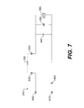
- FIG. 7 is a schematic diagram of a preferred electrical circuit for the vaporizer shown in FIG. 1.
- FIGS. 8 and 9 are, respectively, rear and front perspective views of another vaporizer incorporating a preferred rotatable plug assembly.
- FIG. 10 is an exploded assembly view of the vaporizer shown in FIGS. 8 and 9.
- FIG. 11 is a view, similar to that of FIG. 10, in which the vaporizer is provided with a fan.
- FIG. 12 is a view, similar to that of FIG. 10, but from a different viewpoint, in which the vaporizer is provided with a night light.
- FIG. 13 is a view, similar to that of FIG. 12, in which the vaporizer is provided with an indicator light.
- FIGS. 1 - 7 illustrate a vaporizer 100 incorporating a preferred rotatable plug assembly according to our invention.
- the vaporizer 100 comprises a multi-piece housing 110 in which a bottle 120 is detachably retained.
- the bottle 120 contains an evaporable substance (not shown), such as, for example, a liquid formulation including a chemical active such as an insecticide, fragrance, odor eliminator, or the like.
- a liquid formulation including a chemical active such as an insecticide, fragrance, odor eliminator, or the like.
- the term “bottle” is used herein in its broadest possible sense, including any receptacle, container, pouch, etc., capable of holding a liquid formulation.
- a raised pattern 130 on one side of the bottle is engaged by an opening 140 in a front shell 150 of the vaporizer housing 110 , while a similar raised pattern (not shown) on an opposite side of the bottle 120 is engaged by a recess 170 (shown in FIG. 3) in a middle shell 180 , in order to secure the bottle 120 within the vaporizer 100 .
- the front shell 150 is sufficiently pliant so that pulling the bottle 120 in a downward direction causes the raised patterns 130 to release from the opening 140 in the front shell 150 and the recess 170 in the middle shell 180 , respectively, thereby enabling removal of the bottle 120 from the vaporizer 100 .
- the neck portion of the bottle may be designed to snap or screw into the vaporizer housing.
- Suitable refill bottles are available in a wide variety of liquid formulations from S.C. Johnson & Son, Inc., of Racine, Wisconsin, under the GLADE® PLUGINS® and RAID® brand names.
- the bottle 120 includes a wick 190 for drawing the liquid formulation out of the bottle 120 and toward an upper portion of the wick 190 .
- a lower portion of the wick 190 is immersed in the liquid formulation, and the upper portion of the wick 190 protrudes above the neck of the bottle 120 .
- the wick 190 is positioned within the bottle 120 by a cap 200 which includes a sheath 210 that encases the upper portion of the wick 190 , except for an open area near the tip of the wick 190 .
- a cap without a sheath can be utilized.
- the wick is about 7 mm in diameter and is constructed of ultra high molecular weight high density polyethylene.
- the vaporizer housing 110 comprises three shells—the front and middle shells 150 , 180 noted above and a back shell 220 —which are fastened together by heat-staking or any other suitable fastening means, including, for example, rivets, press fit, snap fit, screws, ultrasonic welding, adhesives, or the like.
- the electrical components (discussed in more detail below) of the vaporizer 100 are housed within the space enclosed by the middle and back shells 180 , 220 .
- the back shell 220 contains a circular opening in which an electrical plug assembly 230 is seated.
- the plug assembly 230 serves the dual purpose of supplying power to the electrical components of the vaporizer 100 and also supporting the vaporizer 100 in a wall outlet (not shown).
- the plug assembly 230 is rotatable 360 degrees in order to support the vaporizer 100 in an upright position in both horizontal and vertical polarized wall outlets.
- the plug assembly 230 can be provided with an extra outlet 160 which is located on the side of the vaporizer 100 when the vaporizer is plugged into a vertical wall outlet (see FIGS. 1 and 5) and on the bottom of the vaporizer 100 when the vaporizer is plugged into a horizontal wall outlet (see FIG. 6).
- the plug assembly 230 comprises a stepped, cylindrically-shaped body 360 .
- Plug blades 370 protrude through narrow slits 380 in the rear face of the plug assembly body 360 , in a direction parallel to the axis of rotation of the plug assembly 230 .
- each plug blade 370 includes a spring contact 390 at its distal end and a sliding contact 400 .
- the sliding contacts 400 protrude slightly through openings 410 provided on opposite sides of the plug assembly body 360 .
- the plug blades 370 including the spring contacts 390 and sliding contacts 400 , preferably are made of nickel-plated brass, although other well-known conductive materials could also be utilized.
- the plug assembly 230 includes at least one, and preferably two, extra outlets 160 .
- two extra outlets 160 are provided on opposite sides of the plug assembly body 360 , spaced approximately 180 degrees apart from each other.
- a pair of rigid conductive members 420 are press fit over the spring contacts 390 , thereby electrically connecting the extra outlets 160 to the plug blades 370 .
- the conductive members 420 do not contact each other.
- the conductive members 420 are made of brass, although other well-known conductive materials could also be utilized.
- the plug assembly 230 rotates within a lower portion of the vaporizer housing 110 .
- a pair of contact carriers 430 is fixed within the housing 110 , substantially surrounding the cylindrical surface of the plug assembly 230 .
- the contact carriers 430 are made of phosphor bronze, but other well-known conductive materials could also be utilized.
- the contact carriers 430 selectively provide an electrical connection between the plug assembly 230 and the electrical components of the vaporizer 100 .
- the contact carriers 430 include four electrical contacts 440 spaced around the plug assembly 230 approximately 90 degrees apart from each other. Opposing pairs of contacts 440 are sized to receive the sliding contacts 400 of the plug blades 370 at each of four 90-degree intervals of rotation of the plug assembly 230 .
- the sliding contacts 400 preferably are tapered along their edges, as indicated in FIG. 4.
- the plug assembly 230 is capable of conducting power to the electrical components of the vaporizer 100 at each of the four possible 90-degree intervals of rotation of the plug assembly 230 .
- the plug assembly 230 of our invention is capable of being rotated in either direction any number of times, and still will provide the required electrical connections at each 90-degree interval of rotation.
- the vaporizer housing 110 includes three windows 460 —one on the bottom of the vaporizer 100 and one on each side.
- the windows 460 are positioned such that at least one of the extra outlets 160 is accessible through a window at at least two of the four possible 90-degree intervals of rotation of the plug assembly 230 .
- the extra outlets 160 are aligned with windows 460 on opposite sides of the housing 110
- the rotated orientation shown FIG. 6 only one of the extra outlets 160 is accessible through the window 460 in the bottom of the housing 110 .
- the plug assembly 230 includes two extra outlets 160 on opposite sides thereof, at least one of the extra outlets 160 will be accessible at each of the four possible 90-degree intervals of rotation. If there is only one extra outlet, it will be accessible at three of the four 90-degree intervals of rotation.
- the vaporizer 100 can have just two windows 460 provided on mutually orthogonal sides of the housing 110 , e.g., on the side and bottom.
- the plug assembly 230 includes two extra outlets 160 on opposite sides thereof, one of the extra outlets 160 will be accessible at each of the four possible 90-degree intervals of rotation. If there is only one extra outlet, it will be accessible at two of the four 90-degree intervals of rotation.
- the rotatable plug assembly 230 is incorporated in a liquid vaporizer, those skilled in the art will understand that the plug assembly can be utilized in many different types of wall-mounted, plug-in appliances, such as non-liquid fragrance dispensers, non-liquid insect control devices, night lights, timers, and the like.
- Each contact carrier 430 is electrically connected by a pin 600 , 610 to a circuit board 240 , which, in turn, is electrically connected to a heating device 250 and, preferably, also to a fan unit 260 .
- the beating device 250 is disposed adjacent to a window 270 in the middle shell 180 which faces the tip of the wick 190 when the bottle 120 is inserted in the vaporizer. Heating the wick 190 enhances the rate at which the liquid formulation evaporates into the surrounding environment, as described more fully below.
- the heating device 250 is a 1.9 k ⁇ , 7 W metal oxide resistor potted in a ceramic block.
- the resistor preferably has PTC (positive temperature coefficient) characteristics, meaning that its resistance value increases slightly as the resistor heats up.
- PTC positive temperature coefficient
- a suitable resistor is available from Great Land Enterprise Co., Ltd., of Shenzhen, China, for example.
- the heating device 250 can comprise one or more other types of resistor heaters, a wire-wound heater, a PTC heater, or the like.
- the fan unit 260 is disposed within an upper portion of the housing 110 .
- the back shell 220 includes air inlets 280 (shown in FIG. 2) for supplying air to the fan unit 260 .
- the fan unit 260 creates an airstream that entrains the evaporated liquid formulation and assists in the dispersion of the chemical active into the surrounding environment.
- the flow rate of the fan unit 260 within the vaporizer 100 is approximately 0.5 cubic feet per minute, and the fan speed is approximately 2800-3800 RPM.
- a suitable fan unit 260 is a 12 V, DC, brushless fan, such as available from Power Logic Tech. Inc., of Tapei-Hsien, Taiwan.
- other DC or AC fans could be utilized, with appropriate adjustments to the circuit board 240 , which is described more fully below.
- FIG. 7 is a schematic diagram of a preferred circuit board 240 for the vaporizer 100 .
- the circuit board 240 is constructed of a flame-rated material.
- the pins 600 , 610 of the circuit board 240 are provided in electrical contact with the respective contact carriers 430 .
- the voltage applied across the pins 600 , 610 is 120 V, at a frequency of 60 Hz.
- the heating device 250 is connected to the circuit board 240 by a pair of rivets 620 , 630 .
- the circuit board 240 also includes a 1N 4007 diode 660 .
- the power consumption across the entire circuit is about 3.5 W to about 4.0 W.
- louver structure 290 Immediately downstream of the fan unit 260 is a louver structure 290 , shown in FIG. 3, comprising at least one louver and, more preferably, a plurality of louvers 300 .
- the louver structure 290 is an integral part of the middle shell 150 , but it can also be provided separately from the middle shell 150 .
- the louvers 300 are angled upwardly and away from the heating device 250 and the upper portion of the wick 190 , preferably at an angle between about 20 degrees to about 60 degrees relative to horizontal when the vaporizer 100 is in an upright position.
- the optimum louver angle varies depending on such factors as the fan speed and the air exchange rate within the room in which the vaporizer 100 is located. In rooms with relatively low air exchange rates (e.g., between about 0.6 to about 1.2 exchanges per hour), a louver angle of about 40 degrees to about 45 degrees relative to horizontal is preferred. In rooms with higher air exchange rates, a louver angle of about 25 degrees to about 30 degrees relative to horizontal is preferred.
- the middle shell 180 is shaped so as to direct the airstream created by the fan unit 260 through the louvers 300 . Notably, the middle shell 180 does not permit stray currents of air to recirculate within the housing 110 , where those currents could have an undesirable cooling effect on the heating device 250 .
- a pair of openings 225 (shown in FIG. 2) in the side of the vaporizer 100 helps to achieve proper air circulation through the vaporizer.
- the front shell 150 includes a plurality of vents 310 through which the airstream exits the vaporizer 100 after passing through the louvers 300 . As the airstream exits the vaporizer through the vents 310 , it entrains the evaporated liquid formulation, which rises from the wick 190 through an opening 320 in the front shell 150 below the vents 310 .
- the vaporizer 100 also includes an adjustment mechanism 330 that positions the upper portion of the wick 190 with respect to the heating device 250 .
- the adjustment mechanism 330 includes a hollow cylindrical portion 340 that surrounds and engages part of the upper portion of the wick 190 , preferably at a location where the wick 190 is encased by the sheath 210 .
- the adjustment mechanism 330 also includes a dial portion 350 , accessible from outside the vaporizer housing 110 , for rotating the cylindrical portion 340 about an axis of rotation.
- Rotating the dial portion 350 of the adjustment mechanism 330 causes the wick 190 to move toward or away from the heating device 250 in a lateral direction, i.e., in a direction substantially perpendicular to the longitudinal axis of the wick 190 .
- FIGS. 8 - 13 Further preferred embodiments of our invention are illustrated in FIGS. 8 - 13 .
- a vaporizer including a first shell 1 and a second shell 2 that can be joined together in any well-known manner, including rivets, screws, heat-staking, or the like.
- the first and second shells 1 and 2 together form the core housing structure of the vaporizer.
- the housing structure contains many of the basic functional components of the vaporizer, as well as one or more additional functional devices. As shown in FIGS.
- basic components of the vaporizer include a rotatable electrical plug assembly S, a contact carrier M having several electrical contacts, an electrical heating device R connected to a pair of contacts M R of the contact carrier M, a bottle F containing the liquid substance to be evaporated, and a wick W for drawing the liquid substance out of the bottle and toward an upper portion of the wick.
- the plug assembly S is of the sliding-contact type and has contacts S M for engagement with either of two possible corresponding pairs of contacts M S on the contact carrier M.
- the pairs of contacts M S on the contact carrier M are mutually offset by approximately 90 degrees, allowing the plug to be rotated through a range of 360 degrees. This makes the vaporizer easily adaptable for use in both horizontal and vertical electrical outlets, as are found in different parts of the world.
- the vaporizer is completed by a cover 3 , which preferably surrounds substantially the entire outer surface of the second shell 2 such that substantially only the cover is visible when looking at the vaporizer head-on.
- the cover 3 is joined to the housing structure, preferably to the second shell 2 , by any suitable fastening means.
- the cover 3 includes one or more access windows corresponding to whatever additional functional device(s) the vaporizer is equipped with. Apart from these minimal functional considerations, the cover design may be tailored to meet consumers' aesthetic preferences.
- An advantageous feature of our invention is that it permits any of several different additional functional devices to be incorporated in the vaporizer, without requiring any substantial modification to either the core housing structure or the basic functional components of the vaporizer.
- the housing structure in advance, is configured to receive any of the additional functional devices.
- the design of the cover 3 meanwhile, can be varied depending on the additional functional device(s) that the vaporizer is equipped with and the aesthetic preferences of a particular market.
- Additional functional devices for the vaporizer may include, for example, a draft regulator, a wick adjustment mechanism, a fan, a night light, an indicator light, a programmable user interface, or the like.
- the vaporizer includes an extra electrical outlet.
- a pair of metal strips 5 is provided within the body of the rotating plug assembly S. One end of each strip 5 is press-fitted into engagement with spring contacts on the pins of the plug, while the other end has a clamping system 5 p for connecting to an electrical plug.
- the extra electrical outlet is accessible via either of two windows 5 f provided in the first shell 1 , depending on the position assumed by the plug assembly S.
- FIG. 11 illustrates a vaporizer including a fan as an additional functional device.
- the fan is housed in the top part of the first and second shells 1 and 2 , which are provided, for this purpose, with a wide cavity.
- This cavity houses a printed electrical circuit 10 and a fan assembly 11 that is powered and controlled by the circuit 10 .
- the circuit 10 is in turn powered by means of a pair of contacts M 10 (which is precisely the same pair of contacts M R described above in connection with FIG. 10).
- the heating device R is connected to the circuit 10 instead of directly to the contact carrier M.
- the circuit 10 is equipped with a switch 10 a that is accessible through a window 10 f in the first shell 1 .
- FIG. 12 illustrates a vaporizer including a night light 12 as an additional functional device.
- the night light 12 may be chosen from among various well-known types of commercially-available devices, such as incandescent lamps, neon lamps, LED devices (as shown in FIG. 12), or the like. If desired, a diffusing lens 12 a may also be utilized.
- the electrical connections in this embodiment are identical to those discussed above with respect to FIG. 11.
- FIG. 13 illustrates a vaporizer including a programmable user interface 13 as an additional functional device.
- the interface includes three LED devices.
- the LED devices preferably have a much lower wattage than those used in the night light embodiment, because they are not intended to provide illumination, but rather only signal the different operating modes of the vaporizer.
- a diffusing lens 13 a may also be used in this embodiment, if desired.
- the electrical connections in this embodiment are identical to those discussed above with respect to FIG. 11.
- the vaporizer can simply be provided with a cover 3 having the desired aesthetic characteristics and only those access windows that are necessary based on the particular additional functional devices that the vaporizer is equipped with.
- the additional functional devices are easily inserted into their respective places and connected to the electrical contacts already provided in the first and second shells 1 and 2 .
Abstract
A wall-mounted, plug-in appliance includes a housing and a plug assembly, which is rotatably disposed within the housing. The plug assembly includes (i) a plug for electrically connecting the plug assembly to a wall outlet and (ii) at least one integral extra outlet to which another electrical appliance can be plugged in. The plug assembly conducts power to electrical components of the appliance at each of at least two 90-degree intervals of rotation of the plug assembly, and the extra outlet is accessible through different ones of a plurality of windows in the housing at different 90-degree intervals of rotation of the plug assembly.
Description
- This application is a continuation-in-part of U.S. patent application Ser. No. 10/212,746, filed Aug. 7, 2002. This application also claims the benefit of U.S. Provisional Patent Application No. 60/371,162, filed Apr. 10, 2002.
- 1. Field of the Invention
- Our invention relates generally to a rotatable plug assembly for incorporation in an electrical appliance, and, particularly, to a rotatable plug assembly equipped with one or more extra electrical outlets.
- 2. Description of the Related Art
- Plug-in electrical appliances such as vaporizers, night lights, timers, and the like, are well known in the art. Typically, these devices are left plugged into a wall outlet for extended periods of time, thereby preventing or limiting the use of other electrical appliances in the outlet. To address this problem, several patents propose electrical appliances having an extra outlet to replace the one occupied by the plugged-in appliance. U.S. Pat. Nos. 5,937,140 and 6,478,440, each of which is incorporated by reference herein, disclose examples of plug-in appliances with extra outlets.
- Some types of plug-in appliances, particularly wick-based liquid vaporizers, must be in an upright orientation in order to work properly. Because some outlets are vertical (i.e., one socket is above another one), while other outlets are horizontal (i.e., side-by-side sockets), it is preferable for these appliances to have a rotatable plug which permits the device to be used in both vertical and horizontal outlets. U.S. Pat. No. 5,647,053, which also is incorporated by reference herein, discloses a wick-based liquid vaporizer having a rotatable plug.
- In one aspect, our invention relates to a wall-mounted, plug-in appliance including a housing and a plug assembly. The plug assembly is rotatably disposed within the housing and includes (i) a plug for electrically connecting the plug assembly to a wall outlet and (ii) at least one integral extra outlet to which another electrical appliance can be plugged in. The plug assembly conducts power to electrical components of the appliance at each of at least two 90-degree intervals of rotation of the plug assembly, and the extra outlet is accessible through different ones of a plurality of windows in the housing at different 90-degree intervals of rotation of the plug assembly.
- In another aspect, our invention relates to a wall-mounted, plug-in appliance including a housing and a plug assembly. The plug assembly is rotatably disposed within the housing and includes (i) a set of plug blades, extending in a direction parallel to the axis of rotation of the plug assembly, for electrically connecting the plug assembly to a wall outlet, and (ii) at least one integral extra outlet for receiving a set of plug blades of another electrical device. The extra outlet is oriented such that the plug blades of the other electrical device, when inserted into the extra outlet, extend in a direction substantially perpendicular to the axis of rotation of the plug assembly. The plug assembly electrically connects electrical components of the appliance to the wall outlet at each of four 90-degree intervals of rotation of the plug assembly, and the extra outlet is accessible through different ones of a plurality of windows in the housing at at least two of the four 90-degree intervals of rotation.
- In yet another aspect, our invention relates to an electrical plug-in device for dispersing a chemical active into a surrounding environment. The device includes a housing with a plurality of windows, at least one electrical component contained within the housing for enhancing dispersion of the chemical active to the surrounding environment, and a plug assembly rotatably disposed within the housing. The plug assembly includes (i) a plug for electrically connecting the plug assembly to a wall outlet and (ii) at least one integral extra outlet to which another electrical appliance can be plugged in. The plug assembly conducts power to the electrical component at each of at least two 90-degree intervals of rotation of the plug assembly, and the extra outlet is accessible through different ones of the plurality of windows in the housing at different 90-degree intervals of rotation of the plug assembly.
- In still another aspect, our invention relates to a plug-in vaporizer for dispersing a chemical active into a surrounding environment. The vaporizer includes (i) a bottle containing a liquid formulation including at least one chemical active, (ii) a wick, having a lower portion disposed within the bottle and an upper portion protruding from the bottle, for drawing the liquid formulation from the bottle toward the upper portion of the wick, (iii) a housing in which the bottle is detachably retained, the housing including a plurality of windows, (iv) an electrical heating device, disposed within the housing at a position proximate to the upper portion of the wick, for enhancing evaporation of the liquid formulation from the upper portion of the wick, and (v) a plug assembly rotatably disposed within the housing for supplying power to the heating device. The plug assembly includes a set of plug blades, extending in a direction parallel to the axis of rotation of the plug assembly, for electrically connecting the plug assembly to a wall outlet, and at least one integral extra outlet for receiving a set of plug blades of another electrical appliance. The extra outlet is oriented such that the plug blades of the other electrical appliance, when inserted into the extra outlet, extend in a direction substantially perpendicular to the axis of rotation of the plug assembly. The plug assembly electrically connects the electrical components of the appliance to the wall outlet at each of four 90-degree intervals of rotation of the plug assembly, and the extra outlet is accessible through different ones of the plurality of windows in the housing at at least two of the four 90-degree intervals of rotation.
- A better understanding of these and other features and advantages of our invention may be had by reference to the drawings and to the accompanying description, in which preferred embodiments of the invention are illustrated and described.
- FIG. 1 is a perspective view of a vaporizer incorporating a preferred rotatable plug assembly.
- FIG. 2 is a rotated perspective view of the vaporizer shown in FIG. 1.
- FIG. 3 is an exploded assembly view of the vaporizer shown in FIG. 1.
- FIG. 4 is an exploded assembly view of the rotatable plug assembly of the vaporizer shown in FIG. 1.
- FIG. 5 is a perspective view of the rotatable plug assembly shown in FIG. 4, configured for insertion into a vertical wall outlet.
- FIG. 6 is a perspective view of the rotatable plug assembly shown in FIG. 4, configured for insertion into a horizontal wall outlet.
- FIG. 7 is a schematic diagram of a preferred electrical circuit for the vaporizer shown in FIG. 1.
- FIGS. 8 and 9 are, respectively, rear and front perspective views of another vaporizer incorporating a preferred rotatable plug assembly.
- FIG. 10 is an exploded assembly view of the vaporizer shown in FIGS. 8 and 9.
- FIG. 11 is a view, similar to that of FIG. 10, in which the vaporizer is provided with a fan.
- FIG. 12 is a view, similar to that of FIG. 10, but from a different viewpoint, in which the vaporizer is provided with a night light.
- FIG. 13 is a view, similar to that of FIG. 12, in which the vaporizer is provided with an indicator light.
- FIGS. 1-7 illustrate a
vaporizer 100 incorporating a preferred rotatable plug assembly according to our invention. As shown in FIG. 1, thevaporizer 100 comprises amulti-piece housing 110 in which abottle 120 is detachably retained. Thebottle 120 contains an evaporable substance (not shown), such as, for example, a liquid formulation including a chemical active such as an insecticide, fragrance, odor eliminator, or the like. The term “bottle” is used herein in its broadest possible sense, including any receptacle, container, pouch, etc., capable of holding a liquid formulation. A raisedpattern 130 on one side of the bottle is engaged by an opening 140 in afront shell 150 of thevaporizer housing 110, while a similar raised pattern (not shown) on an opposite side of thebottle 120 is engaged by a recess 170 (shown in FIG. 3) in amiddle shell 180, in order to secure thebottle 120 within thevaporizer 100. Thefront shell 150 is sufficiently pliant so that pulling thebottle 120 in a downward direction causes the raisedpatterns 130 to release from theopening 140 in thefront shell 150 and therecess 170 in themiddle shell 180, respectively, thereby enabling removal of thebottle 120 from thevaporizer 100. Alternatively, the neck portion of the bottle may be designed to snap or screw into the vaporizer housing. Suitable refill bottles are available in a wide variety of liquid formulations from S.C. Johnson & Son, Inc., of Racine, Wisconsin, under the GLADE® PLUGINS® and RAID® brand names. - As shown in FIG. 3, the
bottle 120 includes awick 190 for drawing the liquid formulation out of thebottle 120 and toward an upper portion of thewick 190. A lower portion of thewick 190 is immersed in the liquid formulation, and the upper portion of thewick 190 protrudes above the neck of thebottle 120. Preferably, thewick 190 is positioned within thebottle 120 by acap 200 which includes asheath 210 that encases the upper portion of thewick 190, except for an open area near the tip of thewick 190. Alternatively, a cap without a sheath can be utilized. Preferably, the wick is about 7 mm in diameter and is constructed of ultra high molecular weight high density polyethylene. - In the preferred embodiment illustrated in FIGS. 1-7, the
vaporizer housing 110 comprises three shells—the front andmiddle shells back shell 220—which are fastened together by heat-staking or any other suitable fastening means, including, for example, rivets, press fit, snap fit, screws, ultrasonic welding, adhesives, or the like. The electrical components (discussed in more detail below) of thevaporizer 100 are housed within the space enclosed by the middle andback shells - Referring to FIG. 2, the
back shell 220 contains a circular opening in which anelectrical plug assembly 230 is seated. Theplug assembly 230 serves the dual purpose of supplying power to the electrical components of thevaporizer 100 and also supporting thevaporizer 100 in a wall outlet (not shown). Preferably, theplug assembly 230 is rotatable 360 degrees in order to support thevaporizer 100 in an upright position in both horizontal and vertical polarized wall outlets. Advantageously, theplug assembly 230 can be provided with anextra outlet 160 which is located on the side of thevaporizer 100 when the vaporizer is plugged into a vertical wall outlet (see FIGS. 1 and 5) and on the bottom of thevaporizer 100 when the vaporizer is plugged into a horizontal wall outlet (see FIG. 6). - As illustrated in FIG. 4- 6, the
plug assembly 230 comprises a stepped, cylindrically-shapedbody 360.Plug blades 370 protrude throughnarrow slits 380 in the rear face of theplug assembly body 360, in a direction parallel to the axis of rotation of theplug assembly 230. In the preferred embodiment shown, eachplug blade 370 includes aspring contact 390 at its distal end and a slidingcontact 400. As best illustrated in FIGS. 5 and 6, the slidingcontacts 400 protrude slightly throughopenings 410 provided on opposite sides of theplug assembly body 360. Theplug blades 370, including thespring contacts 390 and slidingcontacts 400, preferably are made of nickel-plated brass, although other well-known conductive materials could also be utilized. - The
plug assembly 230 includes at least one, and preferably two,extra outlets 160. In the preferred embodiment shown, twoextra outlets 160 are provided on opposite sides of theplug assembly body 360, spaced approximately 180 degrees apart from each other. A pair of rigidconductive members 420 are press fit over thespring contacts 390, thereby electrically connecting theextra outlets 160 to theplug blades 370. Theconductive members 420 do not contact each other. Preferably, theconductive members 420 are made of brass, although other well-known conductive materials could also be utilized. - The
plug assembly 230 rotates within a lower portion of thevaporizer housing 110. A pair ofcontact carriers 430 is fixed within thehousing 110, substantially surrounding the cylindrical surface of theplug assembly 230. Preferably, thecontact carriers 430 are made of phosphor bronze, but other well-known conductive materials could also be utilized. Thecontact carriers 430 selectively provide an electrical connection between theplug assembly 230 and the electrical components of thevaporizer 100. In the preferred embodiment shown, thecontact carriers 430 include fourelectrical contacts 440 spaced around theplug assembly 230 approximately 90 degrees apart from each other. Opposing pairs ofcontacts 440 are sized to receive the slidingcontacts 400 of theplug blades 370 at each of four 90-degree intervals of rotation of theplug assembly 230. To facilitate this, the slidingcontacts 400 preferably are tapered along their edges, as indicated in FIG. 4. Thus, in the preferred embodiment shown, theplug assembly 230 is capable of conducting power to the electrical components of thevaporizer 100 at each of the four possible 90-degree intervals of rotation of theplug assembly 230. Theplug assembly 230 of our invention is capable of being rotated in either direction any number of times, and still will provide the required electrical connections at each 90-degree interval of rotation. - Preferably, the
vaporizer housing 110 includes threewindows 460—one on the bottom of thevaporizer 100 and one on each side. Thewindows 460 are positioned such that at least one of theextra outlets 160 is accessible through a window at at least two of the four possible 90-degree intervals of rotation of theplug assembly 230. In the orientation shown in FIG. 5, for example, theextra outlets 160 are aligned withwindows 460 on opposite sides of thehousing 110, whereas in the rotated orientation shown FIG. 6, only one of theextra outlets 160 is accessible through thewindow 460 in the bottom of thehousing 110. Thus, if theplug assembly 230 includes twoextra outlets 160 on opposite sides thereof, at least one of theextra outlets 160 will be accessible at each of the four possible 90-degree intervals of rotation. If there is only one extra outlet, it will be accessible at three of the four 90-degree intervals of rotation. - Alternatively, the
vaporizer 100 can have just twowindows 460 provided on mutually orthogonal sides of thehousing 110, e.g., on the side and bottom. In this case, if theplug assembly 230 includes twoextra outlets 160 on opposite sides thereof, one of theextra outlets 160 will be accessible at each of the four possible 90-degree intervals of rotation. If there is only one extra outlet, it will be accessible at two of the four 90-degree intervals of rotation. - Although in the preferred embodiment described above the
rotatable plug assembly 230 is incorporated in a liquid vaporizer, those skilled in the art will understand that the plug assembly can be utilized in many different types of wall-mounted, plug-in appliances, such as non-liquid fragrance dispensers, non-liquid insect control devices, night lights, timers, and the like. - The electrical components of the
vaporizer 100 alluded to above will now be described with reference to FIGS. 3 and 7. Eachcontact carrier 430 is electrically connected by apin circuit board 240, which, in turn, is electrically connected to aheating device 250 and, preferably, also to afan unit 260. Thebeating device 250 is disposed adjacent to awindow 270 in themiddle shell 180 which faces the tip of thewick 190 when thebottle 120 is inserted in the vaporizer. Heating thewick 190 enhances the rate at which the liquid formulation evaporates into the surrounding environment, as described more fully below. Preferably, theheating device 250 is a 1.9 kΩ, 7 W metal oxide resistor potted in a ceramic block. The resistor preferably has PTC (positive temperature coefficient) characteristics, meaning that its resistance value increases slightly as the resistor heats up. A suitable resistor is available from Great Land Enterprise Co., Ltd., of Shenzhen, China, for example. Alternatively, theheating device 250 can comprise one or more other types of resistor heaters, a wire-wound heater, a PTC heater, or the like. - The
fan unit 260 is disposed within an upper portion of thehousing 110. Theback shell 220 includes air inlets 280 (shown in FIG. 2) for supplying air to thefan unit 260. As described more fully below, thefan unit 260 creates an airstream that entrains the evaporated liquid formulation and assists in the dispersion of the chemical active into the surrounding environment. Preferably, the flow rate of thefan unit 260 within thevaporizer 100 is approximately 0.5 cubic feet per minute, and the fan speed is approximately 2800-3800 RPM. Asuitable fan unit 260 is a 12 V, DC, brushless fan, such as available from Power Logic Tech. Inc., of Tapei-Hsien, Taiwan. Alternatively, other DC or AC fans could be utilized, with appropriate adjustments to thecircuit board 240, which is described more fully below. - FIG. 7 is a schematic diagram of a
preferred circuit board 240 for thevaporizer 100. Preferably, thecircuit board 240 is constructed of a flame-rated material. Thepins circuit board 240 are provided in electrical contact with therespective contact carriers 430. The voltage applied across thepins heating device 250 is connected to thecircuit board 240 by a pair ofrivets W Zener diode 640, (ii) a 22 μF, 50 V aluminumelectrolytic capacitor 650, rated for a temperature of 105° C., and (iii) thefan unit 260. Thecircuit board 240 also includes a 1N 4007diode 660. The power consumption across the entire circuit is about 3.5 W to about 4.0 W. Those skilled in the art will appreciate that numerous alternative circuit configurations are possible and that values will vary depending on the applied voltage. - Immediately downstream of the
fan unit 260 is alouver structure 290, shown in FIG. 3, comprising at least one louver and, more preferably, a plurality oflouvers 300. Preferably, thelouver structure 290 is an integral part of themiddle shell 150, but it can also be provided separately from themiddle shell 150. As illustrated in FIGS. 3 and 10, thelouvers 300 are angled upwardly and away from theheating device 250 and the upper portion of thewick 190, preferably at an angle between about 20 degrees to about 60 degrees relative to horizontal when thevaporizer 100 is in an upright position. - The optimum louver angle varies depending on such factors as the fan speed and the air exchange rate within the room in which the
vaporizer 100 is located. In rooms with relatively low air exchange rates (e.g., between about 0.6 to about 1.2 exchanges per hour), a louver angle of about 40 degrees to about 45 degrees relative to horizontal is preferred. In rooms with higher air exchange rates, a louver angle of about 25 degrees to about 30 degrees relative to horizontal is preferred. - The
middle shell 180 is shaped so as to direct the airstream created by thefan unit 260 through thelouvers 300. Notably, themiddle shell 180 does not permit stray currents of air to recirculate within thehousing 110, where those currents could have an undesirable cooling effect on theheating device 250. A pair of openings 225 (shown in FIG. 2) in the side of thevaporizer 100 helps to achieve proper air circulation through the vaporizer. - The
front shell 150 includes a plurality ofvents 310 through which the airstream exits thevaporizer 100 after passing through thelouvers 300. As the airstream exits the vaporizer through thevents 310, it entrains the evaporated liquid formulation, which rises from thewick 190 through anopening 320 in thefront shell 150 below thevents 310. - Optionally, the
vaporizer 100 also includes an adjustment mechanism 330 that positions the upper portion of thewick 190 with respect to theheating device 250. Preferably, the adjustment mechanism 330 includes a hollowcylindrical portion 340 that surrounds and engages part of the upper portion of thewick 190, preferably at a location where thewick 190 is encased by thesheath 210. The adjustment mechanism 330 also includes adial portion 350, accessible from outside thevaporizer housing 110, for rotating thecylindrical portion 340 about an axis of rotation. Rotating thedial portion 350 of the adjustment mechanism 330 causes thewick 190 to move toward or away from theheating device 250 in a lateral direction, i.e., in a direction substantially perpendicular to the longitudinal axis of thewick 190. - Further preferred embodiments of our invention are illustrated in FIGS. 8-13. In FIG. 8, there is shown a vaporizer including a first shell 1 and a
second shell 2 that can be joined together in any well-known manner, including rivets, screws, heat-staking, or the like. The first andsecond shells 1 and 2 together form the core housing structure of the vaporizer. The housing structure contains many of the basic functional components of the vaporizer, as well as one or more additional functional devices. As shown in FIGS. 8 and 10, basic components of the vaporizer include a rotatable electrical plug assembly S, a contact carrier M having several electrical contacts, an electrical heating device R connected to a pair of contacts MR of the contact carrier M, a bottle F containing the liquid substance to be evaporated, and a wick W for drawing the liquid substance out of the bottle and toward an upper portion of the wick. - The plug assembly S is of the sliding-contact type and has contacts S M for engagement with either of two possible corresponding pairs of contacts MS on the contact carrier M. The pairs of contacts MS on the contact carrier M are mutually offset by approximately 90 degrees, allowing the plug to be rotated through a range of 360 degrees. This makes the vaporizer easily adaptable for use in both horizontal and vertical electrical outlets, as are found in different parts of the world.
- The vaporizer is completed by a
cover 3, which preferably surrounds substantially the entire outer surface of thesecond shell 2 such that substantially only the cover is visible when looking at the vaporizer head-on. Thecover 3 is joined to the housing structure, preferably to thesecond shell 2, by any suitable fastening means. Thecover 3 includes one or more access windows corresponding to whatever additional functional device(s) the vaporizer is equipped with. Apart from these minimal functional considerations, the cover design may be tailored to meet consumers' aesthetic preferences. - An advantageous feature of our invention is that it permits any of several different additional functional devices to be incorporated in the vaporizer, without requiring any substantial modification to either the core housing structure or the basic functional components of the vaporizer. To that end, the housing structure, in advance, is configured to receive any of the additional functional devices. The design of the
cover 3, meanwhile, can be varied depending on the additional functional device(s) that the vaporizer is equipped with and the aesthetic preferences of a particular market. Additional functional devices for the vaporizer may include, for example, a draft regulator, a wick adjustment mechanism, a fan, a night light, an indicator light, a programmable user interface, or the like. - In the preferred embodiment shown, the vaporizer includes an extra electrical outlet. As shown in FIG. 10, a pair of
metal strips 5 is provided within the body of the rotating plug assembly S. One end of eachstrip 5 is press-fitted into engagement with spring contacts on the pins of the plug, while the other end has aclamping system 5 p for connecting to an electrical plug. The extra electrical outlet is accessible via either of twowindows 5 f provided in the first shell 1, depending on the position assumed by the plug assembly S. - FIG. 11 illustrates a vaporizer including a fan as an additional functional device. The fan is housed in the top part of the first and
second shells 1 and 2, which are provided, for this purpose, with a wide cavity. This cavity houses a printedelectrical circuit 10 and afan assembly 11 that is powered and controlled by thecircuit 10. Thecircuit 10 is in turn powered by means of a pair of contacts M10 (which is precisely the same pair of contacts MR described above in connection with FIG. 10). In this embodiment, the heating device R is connected to thecircuit 10 instead of directly to the contact carrier M. Thecircuit 10 is equipped with aswitch 10 a that is accessible through awindow 10 f in the first shell 1. - FIG. 12 illustrates a vaporizer including a
night light 12 as an additional functional device. Thenight light 12 may be chosen from among various well-known types of commercially-available devices, such as incandescent lamps, neon lamps, LED devices (as shown in FIG. 12), or the like. If desired, a diffusinglens 12a may also be utilized. The electrical connections in this embodiment are identical to those discussed above with respect to FIG. 11. - FIG. 13 illustrates a vaporizer including a
programmable user interface 13 as an additional functional device. In the preferred embodiment shown in FIG. 13, the interface includes three LED devices. The LED devices preferably have a much lower wattage than those used in the night light embodiment, because they are not intended to provide illumination, but rather only signal the different operating modes of the vaporizer. A diffusinglens 13 a may also be used in this embodiment, if desired. The electrical connections in this embodiment are identical to those discussed above with respect to FIG. 11. - From the foregoing description, it should be clear that it is possible to modify the number and type of additional functional devices the vaporizer is equipped with without making any significant modification to its core housing structure, including the first and
second shells 1 and 2. Instead, the vaporizer can simply be provided with acover 3 having the desired aesthetic characteristics and only those access windows that are necessary based on the particular additional functional devices that the vaporizer is equipped with. During manufacture of the vaporizer, the additional functional devices are easily inserted into their respective places and connected to the electrical contacts already provided in the first andsecond shells 1 and 2. - The embodiments discussed above are representative of preferred embodiments of our invention and are provided for illustrative purposes only. They are not intended to limit the scope of the invention. Although specific structures, components, circuits, etc., have been shown and described, such are not limiting. Modifications and variations are contemplated within the scope of our invention, which is intended to be limited only by the scope of the accompanying claims.
Claims (25)
1. A wall-mounted, plug-in appliance, comprising:
a housing containing electrical components of the appliance, the housing including a plurality of windows; and
a plug assembly rotatably disposed within the housing, the plug assembly including (i) a plug for electrically connecting the plug assembly to a wall outlet and (ii) at least one integral extra outlet to which another electrical appliance can be plugged in,
wherein the plug assembly conducts power to the electrical components of the appliance at each of at least two 90-degree intervals of rotation of the plug assembly, and the extra outlet is accessible through different ones of the plurality of windows in the housing at different 90-degree intervals of rotation of the plug assembly.
2. The appliance of claim 1 , wherein the electrical components contained in the housing include at least one of a heating device, a fan, a light, and a circuit board.
3. The appliance of claim 1 , wherein each of two mutually orthogonal sides of the housing includes a respective one of the plurality of windows, each of the two sides being adjacent and substantially perpendicular to a third side of the housing from which the plug of the plug assembly extends.
4. The appliance of claim 1 , wherein a pair of rigid conductive members electrically connects the extra outlet to the plug.
5. The appliance of claim 4 , wherein the plug assembly is substantially cylindrical in shape and includes two integral extra outlets spaced approximately 180 degrees apart on the cylindrical surface of the plug assembly.
6. The appliance of claim 5 , wherein the pair of rigid conductive members electrically connects each extra outlet to the plug.
7. A wall-mounted, plug-in appliance, comprising:
a housing containing electrical components of the appliance, the housing including a plurality of windows; and
a plug assembly rotatably disposed within the housing, the plug assembly including (i) a set of plug blades, extending in a direction parallel to the axis of rotation of the plug assembly, for electrically connecting the plug assembly to a wall outlet, and (ii) at least one integral extra outlet for receiving a set of plug blades of another electrical device, the extra outlet being oriented such that the plug blades of the other electrical device, when inserted into the extra outlet, extend in a direction substantially perpendicular to the axis of rotation of the plug assembly,
wherein the plug assembly electrically connects the electrical components of the appliance to the wall outlet at each of four 90-degree intervals of rotation of the plug assembly, and the extra outlet is accessible through different ones of the plurality of windows in the housing at at least two of the four 90-degree intervals of rotation.
8. The appliance of claim 7 , wherein the extra outlet is accessible through different ones of the plurality of windows in the housing at at least three of the four 90-degree intervals of rotation.
9. The appliance of claim 7 , wherein the electrical components contained in the housing include at least one of a heating device, a fan, a light, and a circuit board.
10. The appliance of claim 7 , wherein each of two mutually orthogonal sides of the housing includes a respective one of the plurality of windows, each of the two sides being adjacent and substantially perpendicular to a third side of the housing from which the plug blades of the plug assembly extend.
11. The appliance of claim 7 , wherein a pair of rigid conductive members electrically connects the extra outlet to the plug blades of the plug assembly.
12. The appliance of claim 11 , wherein the plug assembly is substantially cylindrical in shape and includes two integral extra outlets spaced approximately 180 degrees apart on the cylindrical surface of the plug assembly.
13. The appliance of claim 12 , wherein the pair of rigid conductive members electrically connects each extra outlet to the plug blades of the plug assembly.
14. An electrical plug-in device for dispersing a chemical active into a surrounding environment, the device comprising:
a housing including a plurality of windows;
at least one electrical component contained within the housing for enhancing dispersion of the chemical active to the surrounding environment; and
a plug assembly rotatably disposed within the housing, the plug assembly including (i) a plug for electrically connecting the plug assembly to a wall outlet and (ii) at least one integral extra outlet to which another electrical appliance can be plugged in,
wherein the plug assembly conducts power to the at least one electrical component at each of at least two 90-degree intervals of rotation of the plug assembly, and the extra outlet is accessible through different ones of the plurality of windows in the housing at different 90-degree intervals of rotation of the plug assembly.
15. The device of claim 14 , wherein the at least one electrical component comprises either a heating device or a fan.
16. The device of claim 14 , wherein each of two mutually orthogonal sides of the housing includes a respective one of the plurality of windows, each of the two sides being adjacent and substantially perpendicular to a third side of the housing from which the plug extends.
17. The device of claim 14 , wherein a pair of rigid conductive members electrically connects the extra outlet to the plug.
18. The device of claim 17 , wherein the plug assembly is substantially cylindrical in shape and includes two integral extra outlets spaced approximately 180 degrees apart on the cylindrical surface of the plug assembly.
19. The device of claim 18 , wherein the pair of rigid conductive members electrically connects each extra outlet to the plug.
20. A plug-in vaporizer for dispersing a chemical active into a surrounding environment, the vaporizer comprising:
a bottle containing a liquid formulation including at least one chemical active;
a wick, having a lower portion disposed within the bottle and an upper portion protruding from the bottle, for drawing the liquid formulation from the bottle toward the upper portion of the wick;
a housing in which the bottle is detachably retained, the housing including a plurality of windows;
an electrical heating device, disposed within the housing at a position proximate to the upper portion of the wick, for enhancing evaporation of the liquid formulation from the upper portion of the wick; and
a plug assembly rotatably disposed within the housing for supplying power to the heating device, the plug assembly including (i) a set of plug blades, extending in a direction parallel to the axis of rotation of the plug assembly, for electrically connecting the plug assembly to a wall outlet, and (ii) at least one integral extra outlet for receiving a set of plug blades of another electrical appliance, the extra outlet being oriented such that the plug blades of the other electrical appliance, when inserted into the extra outlet, extend in a direction substantially perpendicular to the axis of rotation of the plug assembly,
wherein the plug assembly electrically connects the electrical components of the appliance to the wall outlet at each of four 90-degree intervals of rotation of the plug assembly, and the extra outlet is accessible through different ones of the plurality of windows in the housing at at least two of the four 90-degree intervals of rotation.
21. The vaporizer of claim 20 , wherein the extra outlet is accessible through different ones of the plurality of windows in the housing at at least three of the four 90-degree intervals of rotation.
22. The vaporizer of claim 20 , wherein each of two mutually orthogonal sides of the housing includes a respective one of the plurality of windows, each of the two sides being adjacent and substantially perpendicular to a third side of the housing from which the plug blades of the plug assembly extend.
23. The vaporizer of claim 20 , wherein a pair of rigid conductive members electrically connects the extra outlet to the plug blades of the plug assembly.
24. The vaporizer of claim 23 , wherein the plug assembly is substantially cylindrical in shape and includes two integral extra outlets spaced approximately 180 degrees apart on the cylindrical surface of the plug assembly.
25. The vaporizer of claim 24 , wherein the pair of rigid conductive members electrically connects each extra outlet to the plug blades of the plug assembly.
Priority Applications (1)
| Application Number | Priority Date | Filing Date | Title |
|---|---|---|---|
| US10/359,097 US6862403B2 (en) | 2001-08-07 | 2003-02-06 | Rotatable plug assembly including an extra outlet |
Applications Claiming Priority (4)
| Application Number | Priority Date | Filing Date | Title |
|---|---|---|---|
| EP01830528A EP1283062B1 (en) | 2001-08-07 | 2001-08-07 | Polyfunctional electric wall evaporator |
| US37116202P | 2002-04-10 | 2002-04-10 | |
| US10/212,746 US6917754B2 (en) | 2001-08-07 | 2002-08-07 | Multi-functional electrical vaporizer for a liquid substance and method of manufacturing such a vaporizer |
| US10/359,097 US6862403B2 (en) | 2001-08-07 | 2003-02-06 | Rotatable plug assembly including an extra outlet |
Related Parent Applications (1)
| Application Number | Title | Priority Date | Filing Date |
|---|---|---|---|
| US10/212,746 Continuation-In-Part US6917754B2 (en) | 2001-08-07 | 2002-08-07 | Multi-functional electrical vaporizer for a liquid substance and method of manufacturing such a vaporizer |
Publications (2)
| Publication Number | Publication Date |
|---|---|
| US20030194225A1 true US20030194225A1 (en) | 2003-10-16 |
| US6862403B2 US6862403B2 (en) | 2005-03-01 |
Family
ID=34279325
Family Applications (1)
| Application Number | Title | Priority Date | Filing Date |
|---|---|---|---|
| US10/359,097 Expired - Fee Related US6862403B2 (en) | 2001-08-07 | 2003-02-06 | Rotatable plug assembly including an extra outlet |
Country Status (1)
| Country | Link |
|---|---|
| US (1) | US6862403B2 (en) |
Cited By (15)
| Publication number | Priority date | Publication date | Assignee | Title |
|---|---|---|---|---|
| US20030175019A1 (en) * | 2002-03-13 | 2003-09-18 | Alper Srl | Electrical dispenser for deodorant or insecticide |
| US20050130968A1 (en) * | 2003-10-03 | 2005-06-16 | Irvine Nicholas M. | Fungicidal 4-(2-aminopyridin-4-yl)-N-phenyl-1,3,5-triazin-2-amine derivatives |
| US6996029B1 (en) * | 2005-04-29 | 2006-02-07 | Stopest Unlimited, Llc | Pest repeller apparatus |
| US20090196585A1 (en) * | 2008-02-04 | 2009-08-06 | Jeff Pohl | Chemical heating assembly |
| US20090278494A1 (en) * | 2008-03-03 | 2009-11-12 | Mitch Randall | Universal electrical interface for providing power to mobile devices |
| US7643734B2 (en) * | 2005-03-31 | 2010-01-05 | S.C. Johnson & Son, Inc. | Bottle eject mechanism |
| WO2010017416A1 (en) * | 2008-08-06 | 2010-02-11 | Wildcharge, Inc. | Universal electrical interface for providing power to mobile devices |
| US7687744B2 (en) | 2002-05-13 | 2010-03-30 | S.C. Johnson & Son, Inc. | Coordinated emission of fragrance, light, and sound |
| USD639923S1 (en) * | 2010-04-15 | 2011-06-14 | S.C. Johnson & Son, Inc. | Dispensing device |
| WO2013043819A2 (en) | 2011-09-22 | 2013-03-28 | S. C. Jonhson & Son, Inc. | Rotatable plug assembly and housing for a volatile material dispenser |
| WO2013066698A1 (en) | 2011-10-28 | 2013-05-10 | S. C. Johnson & Son, Inc. | Rotatable plug assembly and method of reducing strain in a wire |
| WO2014022164A2 (en) | 2012-07-31 | 2014-02-06 | S.C. Johnson & Son, Inc. | Volatile material dispenser and method of emitting a volatile material |
| WO2016160872A1 (en) | 2015-04-01 | 2016-10-06 | S.C. Johnson & Son, Inc. | Methods for emitting and refills for holding two or more compositions |
| US20160373909A1 (en) * | 2015-06-17 | 2016-12-22 | Hive Life, LLC | Wireless audio, security communication and home automation |
| CN106500226A (en) * | 2016-12-19 | 2017-03-15 | 长江大学 | A kind of ultrasonic air conditioner type health care bladeless fan |
Families Citing this family (58)
| Publication number | Priority date | Publication date | Assignee | Title |
|---|---|---|---|---|
| JP2002033362A (en) * | 2000-07-17 | 2002-01-31 | Matsushita Electric Ind Co Ltd | Semiconductor-inspecting device |
| US7309024B2 (en) * | 2003-06-30 | 2007-12-18 | S.C. Johnson & Son, Inc. | Wick assembly for dispensing a volatile liquid from a container and method of assembling same |
| US20060163376A1 (en) * | 2002-10-08 | 2006-07-27 | Lakatos Kara L | Breakable wick for use in a dispenser for a volatile liquid |
| US7007863B2 (en) * | 2002-10-08 | 2006-03-07 | S.C. Johnson & Son, Inc. | Wick-based delivery system with wick made of different composite materials |
| US7244398B2 (en) * | 2003-03-21 | 2007-07-17 | S. C. Johnson & Son, Inc. | Device for dispensing a volatile liquid using a wick in an ambient air stream |
| US7032831B2 (en) | 2003-03-21 | 2006-04-25 | S.C. Johnson & Son, Inc. | Container for a device for dispensing a volatile liquid |
| KR20040072325A (en) * | 2003-02-12 | 2004-08-18 | 삼성전자주식회사 | Air circulation device |
| US20040265189A1 (en) * | 2003-06-27 | 2004-12-30 | Ralph Schwarz | Dispensing system for a volatile liquid |
| US20040195245A1 (en) * | 2003-03-21 | 2004-10-07 | Kishen Gohil | Top mounting for a container for a volatile liquid dispenser |
| US7744833B2 (en) * | 2003-06-27 | 2010-06-29 | S.C. Johnson & Son, Inc. | Volatile liquids having predetermined evaporation profiles |
| JP2008509797A (en) * | 2004-08-20 | 2008-04-03 | ザ ダイアル コーポレイション | Method and apparatus for low profile air purifier |
| TWM264709U (en) * | 2004-10-01 | 2005-05-11 | Sheng-Shing Liau | Compound converting apparatus having rotation function |
| US10505326B2 (en) * | 2013-06-05 | 2019-12-10 | Tseng-Lu Chien | Multiple functions wall cover plate has built-in USB and light means |
| US7281811B2 (en) * | 2005-03-31 | 2007-10-16 | S. C. Johnson & Son, Inc. | Multi-clarity lenses |
| US7368003B2 (en) * | 2005-06-24 | 2008-05-06 | S.C. Johnson & Son, Inc. | Systems for and methods of providing air purification in combination with odor elimination |
| US7537647B2 (en) * | 2005-08-10 | 2009-05-26 | S.C. Johnson & Son, Inc. | Air purifier |
| WO2007056521A2 (en) * | 2005-11-09 | 2007-05-18 | Ashland Licensing And Intellectual Property Llc | Air freshener |
| US20070207066A1 (en) * | 2006-03-02 | 2007-09-06 | Guardian Technologies Llc | Air sterilization device and uses thereof |
| US7540432B2 (en) * | 2006-05-30 | 2009-06-02 | S.C. Johnson & Son, Inc. | Passive dispensing device |
| US7628338B2 (en) * | 2006-09-18 | 2009-12-08 | S.C. Johnson & Son, Inc. | Refill for a volatile material |
| US7736033B2 (en) | 2007-04-20 | 2010-06-15 | Bharat Patel | Lamp base with electrical device recharging receptacle and method |
| US7840123B2 (en) | 2007-06-21 | 2010-11-23 | S.C. Johnson & Son, Inc. | Diffusion device |
| US8320751B2 (en) * | 2007-12-20 | 2012-11-27 | S.C. Johnson & Son, Inc. | Volatile material diffuser and method of preventing undesirable mixing of volatile materials |
| US8197260B2 (en) | 2008-03-07 | 2012-06-12 | Belkin International, Inc. | Electrical connector and method of manufacturing same |
| US20090225486A1 (en) | 2008-03-07 | 2009-09-10 | Belkin International, Inc. | Electrical Connector And Method Of Manufacturing Same |
| TW200947812A (en) * | 2008-05-09 | 2009-11-16 | Delta Electronics Inc | Electronic apparatus having rotatable plug structure |
| US8197762B2 (en) * | 2008-09-29 | 2012-06-12 | S.C. Johnson & Son, Inc. | Method of dispensing a volatile material |
| US8293172B2 (en) * | 2008-09-29 | 2012-10-23 | S.C. Johnson & Son, Inc. | Method of dispensing a volatile material |
| US7845951B1 (en) * | 2009-06-24 | 2010-12-07 | Ngoon Goon | Rotatable adapter for electrical plugs |
| US20110210617A1 (en) * | 2009-08-28 | 2011-09-01 | Pure Energy Solutions, Inc. | Power transmission across a substantially planar interface by magnetic induction and geometrically-complimentary magnetic field structures |
| CN102740899B (en) * | 2009-09-21 | 2015-01-21 | 约翰逊父子公司 | Methods of emitting a volatile material from a diffuser |
| TWI427875B (en) * | 2009-10-28 | 2014-02-21 | Powertech Ind Co Ltd | Rotatable and foldable electric plug connector |
| USD650681S1 (en) | 2009-12-14 | 2011-12-20 | Kristian Buschmann | Bottle |
| USD651088S1 (en) | 2009-12-14 | 2011-12-27 | Kristian Buschmann | Bottle |
| USD646573S1 (en) | 2009-12-14 | 2011-10-11 | Kubicek Chris A | Bottle |
| USD650682S1 (en) | 2009-12-14 | 2011-12-20 | Kristian Buschmann | Bottle |
| USD650684S1 (en) | 2009-12-14 | 2011-12-20 | Kristian Buschmann | Bottle |
| USD650683S1 (en) | 2009-12-14 | 2011-12-20 | Kristian Buschmann | Bottle |
| WO2011081657A2 (en) * | 2009-12-15 | 2011-07-07 | S. C. Johnson & Son, Inc. | Refill, attachment for a refill, and method of retaining a refill |
| US8118616B1 (en) * | 2010-04-22 | 2012-02-21 | Clark Silva L J | Electrical outlet adaptor device |
| US9770524B2 (en) | 2010-07-16 | 2017-09-26 | S. C. Johnson & Son, Inc. | Volatile material dispenser and method of attaching a refill or refills to same |
| US8262399B1 (en) | 2011-04-27 | 2012-09-11 | Quirky Incorporated | Reconfigurable plug strip |
| US9028274B2 (en) | 2011-04-27 | 2015-05-12 | Quirky, Inc. | Reconfigurable plug strip |
| US20120275772A1 (en) * | 2011-04-28 | 2012-11-01 | Belongia David C | Rotating Electrical Plug Assembly for Volatile Material Dispenser |
| US8500492B2 (en) | 2011-10-20 | 2013-08-06 | Quirky Incorporated | Reconfigurable plug adapter |
| US9833530B2 (en) | 2012-11-02 | 2017-12-05 | S.C. Johnson & Son, Inc. | Volatile material dispenser having a faceplate |
| US20140198431A1 (en) * | 2013-01-14 | 2014-07-17 | Mark Medley | Apparatus electrically coupled to a low wall outlet that is configured for easy viewing of a display |
| PL2896407T3 (en) * | 2014-01-15 | 2019-04-30 | Dc & Bv France Holding Sas | An apparatus for diffusing a chemical substance |
| WO2016033531A1 (en) * | 2014-08-28 | 2016-03-03 | Macauda Tom | Electrical power cord with supplemental socket |
| US10010639B2 (en) * | 2015-01-22 | 2018-07-03 | Rimports, Llc | Electrical plug in fragrance dispenser having a removable decorative sheath |
| US11077221B2 (en) | 2016-01-25 | 2021-08-03 | S. C. Johnson & Son, Inc. | Volatile dispenser for use in volatile dispensing systems |
| US10994042B2 (en) | 2016-01-25 | 2021-05-04 | S. C. Johnson & Son, Inc. | Heated air freshener |
| US10940226B2 (en) | 2016-03-01 | 2021-03-09 | S. C. Johnson & Son, Inc. | Dispenser |
| US10764963B2 (en) * | 2016-10-07 | 2020-09-01 | S. C. Johnson & Son, Inc. | Volatile material dispenser |
| US10973944B1 (en) * | 2017-01-31 | 2021-04-13 | Rimports, Llc | Fragrance dispenser with fragrance conservation features |
| US10850690B2 (en) | 2018-01-17 | 2020-12-01 | S. C. Johnson & Son, Inc. | Electronic devices for use in a vehicle and methods of operating the same |
| CN210020490U (en) * | 2019-01-11 | 2020-02-07 | 王晓明 | Improvement type Q version champignon ware |
| US11566817B1 (en) | 2019-03-22 | 2023-01-31 | Anthony Magaro | Air circulation system |
Citations (19)
| Publication number | Priority date | Publication date | Assignee | Title |
|---|---|---|---|---|
| US2305101A (en) * | 1941-01-11 | 1942-12-15 | Pierce John B Foundation | Electrical apparatus |
| US2582800A (en) * | 1946-11-22 | 1952-01-15 | Jesse F Sorenson | Swiveling device for electric current |
| US2611068A (en) * | 1946-04-12 | 1952-09-16 | William H Wellens | Pivotally mounted plug and vaporizer |
| US3123421A (en) * | 1964-03-03 | Rotatable electrical connection | ||
| US3780260A (en) * | 1972-08-04 | 1973-12-18 | E Elsner | Combination night light and liquid vaporizer |
| US4743999A (en) * | 1987-02-13 | 1988-05-10 | Curtis Manufacturing Company, Inc. | Rotary telephone line surge protector and system |
| US4804821A (en) * | 1986-06-24 | 1989-02-14 | Environmental Fragrance Technologies, Ltd. | Aroma diffuser assembly |
| US5038394A (en) * | 1988-02-10 | 1991-08-06 | Earth Chemical Co., Ltd. | Thermal vaporizer |
| US5095647A (en) * | 1989-09-29 | 1992-03-17 | Zobele Industrie Chimiche S.P.A. | Apparatus to keep flying insects, particularly mosquitoes, away from people |
| US5554039A (en) * | 1995-09-29 | 1996-09-10 | Siemens Electric Limited | Quick plug connector for electric distribution system(s) |
| US5647053A (en) * | 1995-10-11 | 1997-07-08 | S. C. Johnson & Son, Inc. | Vapor dipensing device |
| US5926614A (en) * | 1994-08-03 | 1999-07-20 | Steinel Gmbh & Co. Kg | Electric device for the vaporization of additives |
| US5937140A (en) * | 1996-09-23 | 1999-08-10 | S. C. Johnson & Son, Inc. | Thermal-fuse plug-through, plug-in diffuser |
| US5957701A (en) * | 1997-06-06 | 1999-09-28 | Mcmillin; Kenneth G. | Electrical outlet extension |
| US6068490A (en) * | 1997-04-14 | 2000-05-30 | Salzberg; Max | Rotatable electrical connector assembly |
| US6361752B1 (en) * | 1999-05-19 | 2002-03-26 | S. C. Johnson & Son, Inc. | Apparatus for volatilizing and dispensing a chemical into a room environment |
| US6466739B2 (en) * | 2000-07-28 | 2002-10-15 | Zobele Holding S.P.A. | Electric evaporator for insecticides or perfumes in liquid formulation, with adjustable evaporation intensity |
| US6478440B1 (en) * | 2000-03-10 | 2002-11-12 | S.C. Johnson & Son, Inc. | Night light air freshener |
| US20020172512A1 (en) * | 1999-06-16 | 2002-11-21 | Stathakis Kristopher J | Liquid vaporization with housing stabilization system |
Family Cites Families (4)
| Publication number | Priority date | Publication date | Assignee | Title |
|---|---|---|---|---|
| FR2664102B1 (en) | 1990-06-28 | 1994-11-10 | Moulinex Sa | REMOVABLE ELECTRICAL CONNECTOR FOR INSTALLATION BETWEEN AN ELECTRICAL CONSUMPTION APPARATUS AND A WALL SOCKET. |
| USD382658S (en) | 1996-05-28 | 1997-08-19 | San Shih Electrical Enterprise Co., Ltd. | Miniature lamp with electrical plug socket |
| ITMI981276A1 (en) | 1998-06-05 | 1999-12-05 | Zobele Ind Chim | ELECTRIC VAPORIZER OF INSECTICIDES OR PERFUMES IN LIQUID FORMULATIONS WITH DEVICE FOR REGULATING THE INTENSITY OF |
| CA2423814C (en) | 2000-09-26 | 2005-11-22 | S.C. Johnson & Son, Inc. | Modular electrical device for delivery of volatile compounds |
-
2003
- 2003-02-06 US US10/359,097 patent/US6862403B2/en not_active Expired - Fee Related
Patent Citations (19)
| Publication number | Priority date | Publication date | Assignee | Title |
|---|---|---|---|---|
| US3123421A (en) * | 1964-03-03 | Rotatable electrical connection | ||
| US2305101A (en) * | 1941-01-11 | 1942-12-15 | Pierce John B Foundation | Electrical apparatus |
| US2611068A (en) * | 1946-04-12 | 1952-09-16 | William H Wellens | Pivotally mounted plug and vaporizer |
| US2582800A (en) * | 1946-11-22 | 1952-01-15 | Jesse F Sorenson | Swiveling device for electric current |
| US3780260A (en) * | 1972-08-04 | 1973-12-18 | E Elsner | Combination night light and liquid vaporizer |
| US4804821A (en) * | 1986-06-24 | 1989-02-14 | Environmental Fragrance Technologies, Ltd. | Aroma diffuser assembly |
| US4743999A (en) * | 1987-02-13 | 1988-05-10 | Curtis Manufacturing Company, Inc. | Rotary telephone line surge protector and system |
| US5038394A (en) * | 1988-02-10 | 1991-08-06 | Earth Chemical Co., Ltd. | Thermal vaporizer |
| US5095647A (en) * | 1989-09-29 | 1992-03-17 | Zobele Industrie Chimiche S.P.A. | Apparatus to keep flying insects, particularly mosquitoes, away from people |
| US5926614A (en) * | 1994-08-03 | 1999-07-20 | Steinel Gmbh & Co. Kg | Electric device for the vaporization of additives |
| US5554039A (en) * | 1995-09-29 | 1996-09-10 | Siemens Electric Limited | Quick plug connector for electric distribution system(s) |
| US5647053A (en) * | 1995-10-11 | 1997-07-08 | S. C. Johnson & Son, Inc. | Vapor dipensing device |
| US5937140A (en) * | 1996-09-23 | 1999-08-10 | S. C. Johnson & Son, Inc. | Thermal-fuse plug-through, plug-in diffuser |
| US6068490A (en) * | 1997-04-14 | 2000-05-30 | Salzberg; Max | Rotatable electrical connector assembly |
| US5957701A (en) * | 1997-06-06 | 1999-09-28 | Mcmillin; Kenneth G. | Electrical outlet extension |
| US6361752B1 (en) * | 1999-05-19 | 2002-03-26 | S. C. Johnson & Son, Inc. | Apparatus for volatilizing and dispensing a chemical into a room environment |
| US20020172512A1 (en) * | 1999-06-16 | 2002-11-21 | Stathakis Kristopher J | Liquid vaporization with housing stabilization system |
| US6478440B1 (en) * | 2000-03-10 | 2002-11-12 | S.C. Johnson & Son, Inc. | Night light air freshener |
| US6466739B2 (en) * | 2000-07-28 | 2002-10-15 | Zobele Holding S.P.A. | Electric evaporator for insecticides or perfumes in liquid formulation, with adjustable evaporation intensity |
Cited By (23)
| Publication number | Priority date | Publication date | Assignee | Title |
|---|---|---|---|---|
| US20030175019A1 (en) * | 2002-03-13 | 2003-09-18 | Alper Srl | Electrical dispenser for deodorant or insecticide |
| US7687744B2 (en) | 2002-05-13 | 2010-03-30 | S.C. Johnson & Son, Inc. | Coordinated emission of fragrance, light, and sound |
| US20050130968A1 (en) * | 2003-10-03 | 2005-06-16 | Irvine Nicholas M. | Fungicidal 4-(2-aminopyridin-4-yl)-N-phenyl-1,3,5-triazin-2-amine derivatives |
| US7643734B2 (en) * | 2005-03-31 | 2010-01-05 | S.C. Johnson & Son, Inc. | Bottle eject mechanism |
| US6996029B1 (en) * | 2005-04-29 | 2006-02-07 | Stopest Unlimited, Llc | Pest repeller apparatus |
| WO2006118918A1 (en) * | 2005-04-29 | 2006-11-09 | Stopest Unlimited, Llc | Pest repeller apparatus |
| US20090196585A1 (en) * | 2008-02-04 | 2009-08-06 | Jeff Pohl | Chemical heating assembly |
| US7965926B2 (en) * | 2008-02-04 | 2011-06-21 | Group Dekko, Inc. | Chemical heating assembly |
| US20090278494A1 (en) * | 2008-03-03 | 2009-11-12 | Mitch Randall | Universal electrical interface for providing power to mobile devices |
| WO2010017416A1 (en) * | 2008-08-06 | 2010-02-11 | Wildcharge, Inc. | Universal electrical interface for providing power to mobile devices |
| USD639923S1 (en) * | 2010-04-15 | 2011-06-14 | S.C. Johnson & Son, Inc. | Dispensing device |
| US8821171B2 (en) | 2011-09-22 | 2014-09-02 | S.C. Johnson & Son, Inc. | Rotatable plug assembly and housing for a volatile material dispenser |
| WO2013043819A2 (en) | 2011-09-22 | 2013-03-28 | S. C. Jonhson & Son, Inc. | Rotatable plug assembly and housing for a volatile material dispenser |
| WO2013043819A3 (en) * | 2011-09-22 | 2013-06-06 | S. C. Jonhson & Son, Inc. | Rotatable plug assembly and housing for a volatile material dispenser |
| WO2013066698A1 (en) | 2011-10-28 | 2013-05-10 | S. C. Johnson & Son, Inc. | Rotatable plug assembly and method of reducing strain in a wire |
| US8858236B2 (en) | 2011-10-28 | 2014-10-14 | S.C. Johnson & Son, Inc. | Rotatable plug assembly and method of reducing strain in a wire |
| WO2014022164A2 (en) | 2012-07-31 | 2014-02-06 | S.C. Johnson & Son, Inc. | Volatile material dispenser and method of emitting a volatile material |
| EP4129348A2 (en) | 2012-07-31 | 2023-02-08 | S.C. Johnson & Son, Inc. | Refill for a volatile material dispenser |
| WO2016160872A1 (en) | 2015-04-01 | 2016-10-06 | S.C. Johnson & Son, Inc. | Methods for emitting and refills for holding two or more compositions |
| US9783357B2 (en) | 2015-04-01 | 2017-10-10 | S. C. Johnson & Son, Inc. | Methods for emitting and refills for holding two or more compositions |
| US10131483B2 (en) | 2015-04-01 | 2018-11-20 | S. C. Johnson & Son, Inc. | Methods for emitting and refills for holding two or more compositions |
| US20160373909A1 (en) * | 2015-06-17 | 2016-12-22 | Hive Life, LLC | Wireless audio, security communication and home automation |
| CN106500226A (en) * | 2016-12-19 | 2017-03-15 | 长江大学 | A kind of ultrasonic air conditioner type health care bladeless fan |
Also Published As
| Publication number | Publication date |
|---|---|
| US6862403B2 (en) | 2005-03-01 |
Similar Documents
| Publication | Publication Date | Title |
|---|---|---|
| US6862403B2 (en) | Rotatable plug assembly including an extra outlet | |
| EP1492574B1 (en) | Electrical evaporator with adjustable evaporation intensity | |
| CA2481487C (en) | Electrical evaporator including fan and louver structure | |
| EP1283062B1 (en) | Polyfunctional electric wall evaporator | |
| JP4331543B2 (en) | Steam dispensing device | |
| CA2423814C (en) | Modular electrical device for delivery of volatile compounds | |
| EP1685856B1 (en) | Electrical evaporator with rotatable plug deck | |
| CA2402868C (en) | Night light air freshener | |
| US20080226269A1 (en) | Vapor generator | |
| AU2001243552A1 (en) | Night light air freshener | |
| EP1493210B1 (en) | Rotatable plug assembly including an extra outlet | |
| ES2237642T3 (en) | HEATER DEVICE FOR ELECTRODIFUSOR. | |
| EP1393754B1 (en) | Dual electrical outlet vapor-dispenser | |
| MXPA03007341A (en) | Method and apparatus for dual-outlet vapor dispenser | |
| AU2005200261A1 (en) | Vapor-dispensing device |
Legal Events
| Date | Code | Title | Description |
|---|---|---|---|
| AS | Assignment |
Owner name: S.C. JOHNSON & SON, INC., WISCONSIN Free format text: ASSIGNMENT OF ASSIGNORS INTEREST;ASSIGNORS:PEDROTTI, ANDREA;CAMPEDELLI, PAOLO;BALDASSARI, STEFANO;REEL/FRAME:015423/0899 Effective date: 20030416 |
|
| FPAY | Fee payment |
Year of fee payment: 4 |
|
| FPAY | Fee payment |
Year of fee payment: 8 |
|
| REMI | Maintenance fee reminder mailed | ||
| LAPS | Lapse for failure to pay maintenance fees | ||
| STCH | Information on status: patent discontinuation |
Free format text: PATENT EXPIRED DUE TO NONPAYMENT OF MAINTENANCE FEES UNDER 37 CFR 1.362 |
|
| FP | Lapsed due to failure to pay maintenance fee |
Effective date: 20170301 |