US20030193686A1 - Serial data conversion - Google Patents
Serial data conversion Download PDFInfo
- Publication number
- US20030193686A1 US20030193686A1 US10/121,511 US12151102A US2003193686A1 US 20030193686 A1 US20030193686 A1 US 20030193686A1 US 12151102 A US12151102 A US 12151102A US 2003193686 A1 US2003193686 A1 US 2003193686A1
- Authority
- US
- United States
- Prior art keywords
- serial
- printer
- usb
- print command
- based print
- Prior art date
- Legal status (The legal status is an assumption and is not a legal conclusion. Google has not performed a legal analysis and makes no representation as to the accuracy of the status listed.)
- Abandoned
Links
Images


Classifications
-
- G—PHYSICS
- G06—COMPUTING; CALCULATING OR COUNTING
- G06F—ELECTRIC DIGITAL DATA PROCESSING
- G06F13/00—Interconnection of, or transfer of information or other signals between, memories, input/output devices or central processing units
- G06F13/38—Information transfer, e.g. on bus
- G06F13/40—Bus structure
- G06F13/4004—Coupling between buses
- G06F13/4027—Coupling between buses using bus bridges
- G06F13/4045—Coupling between buses using bus bridges where the bus bridge performs an extender function
Definitions
- the present invention relates generally to a method of and apparatus for converting serial data from one format to another.
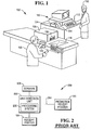
- a register or checkout terminal such as a terminal 100 at a checkout lane 102 of a retail establishment, has an attached printer 104 for printing a receipt for a customer 106 .
- printer 104 is attached using a serial line, e.g., an RS-232 connection, data line to terminal 100 .
- customer 106 provides an item 108 to a checkout operator 110 who rings up the item 108 at terminal 100 and requests payment from customer 106 .
- checkout operator 110 Upon receiving payment and providing change, if appropriate, checkout operator 110 manipulates keys on a keyboard 112 attached to terminal 100 causing a receipt 114 to be printed at attached printer 104 .
- customer 106 interacts directly with a modified version of checkout lane 102 to ring up items and tender payment without needing a checkout operator 110 .
- checkout operator 110 enters information about item 108 to be purchased by customer 106 , e.g., by scanning a bar code 118 on item 108 using a bar code scanner 116 to obtain item information or entering pricing, bar code 118 or other information using keyboard 112 .
- terminal 100 maintains a cumulative total for item 108 to be purchased by customer 106 .
- Terminal 100 may also maintain a list of items including item identifying information, e.g., brand and quantity, and item price to be purchased by customer 106 .
- checkout operator 110 Upon completion of the transaction including payment by customer 106 , checkout operator 110 causes terminal 100 to transmit printing commands for printing the item list and cumulative total price and any additional fees, e.g., taxes, to the attached printer 104 over the serial line (not shown).
- Printer 104 receives the transmitted terminal 100 printing commands and prints receipt 114 to be provided to customer 106 .
- Some checkout terminals include the ability to print promotional receipts, e.g., coupons, rebates, or other discount mechanisms, for future customer use to encourage return shopping.
- promotional receipts e.g., coupons, rebates, or other discount mechanisms
- the ability to print promotional receipts is used as a reward for current shopper purchases.
- a separate promotion receipt printer 120 is used to print the promotional receipt for customer 106 .
- Promotion receipt printer 120 is connected to checkout terminal 100 by a second serial line (not shown) and receives printing commands directly from the checkout terminal.
- checkout terminal 100 may detect the scanning by the checkout clerk 110 of a particular item, e.g., a specific brand of frozen pizza, being purchased by the customer 106 .
- terminal 100 Upon detection of the pizza being scanned at the terminal 100 and subsequent lookup and successful comparison of the item with a list of items predetermined to generate a promotional receipt, the information necessary to print the promotional receipt is transmitted from terminal 100 to the promotion receipt printer 120 . The promotion receipt is then printed and provided to the customer. Terminal 100 determines whether and when to print promotional receipts at promotion receipt printer 120 . In such a configuration, terminal 100 perform the promotional receipt printing determination and issue print commands to both the receipt printer 104 and the promotion receipt printer 120 .
- FIG. 2 is a high level block diagram of an alternate prior art configuration 200 connecting terminal 100 , receipt printer 104 , and promotion receipt printer 120 .
- promotion receipt printer 120 is connected to a line detection unit 202 via a serial connection 204 .
- Line detection unit 202 is attached to the serial connection between the checkout terminal 100 and receipt printer 104 .
- Line detection unit 202 includes a processing system 206 , similar to the controller system 300 described below in connection with FIG. 3, and monitors the transmissions between terminal 100 and receipt printer 104 searching for specific keywords or product identifying information.
- the line detection unit 202 Upon detection of the information, e.g., print commands to print a particular item on printer 104 such as a specific brand of frozen pizza, the line detection unit 202 formats and transmits the necessary print commands to promotion receipt printer 120 and the promotion receipt is then printed and provided to customer 106 .
- the information e.g., print commands to print a particular item on printer 104 such as a specific brand of frozen pizza
- the line detection unit 202 formats and transmits the necessary print commands to promotion receipt printer 120 and the promotion receipt is then printed and provided to customer 106 .
- Line detection unit 202 is known in the art and operates in conjunction with serial printing mechanisms. That is, detection unit 202 detects specific print commands transmitted over a serial line, formats a specific output, e.g., a particular coupon or rebate, and transmits print commands to promotion receipt printer 120 for printing the specific output. In one particular embodiment, detection unit 202 passes through detected print commands directly to promotion receipt printer 120 . In another embodiment, detection unit 202 performs a lookup, e.g., in a table stored in memory, to determine the specific output to be printed in accordance with the print command detected.
- a specific output e.g., a particular coupon or rebate
- USB Universal Serial Bus
- Another object of the present invention is to enable the use of existing line detection unit design.
- Another object of the present invention is to enable the use of existing promotion receipt printer design.
- the above described objects are fulfilled by a method of converting USB-based print commands to serial-based print commands using a printer.
- the printer receives a USB-based print command and converts the received print command to a serial-based print command for transmission over a serial connection for detection by a line detection unit.
- a USB-based printer receives a USB-based print command over a USB connection and has a first serial connection.
- the USB-based printer converts the USB-based print command to a serial-based print command and transmits the serial-based print command over the first serial connection.
- a line detection unit is coupled to the first serial connection of the USB-based printer and detects the converted USB-based print command transmitted as a serial-based print command on the first serial connection.
- the line detection unit transmits a serial-based print command over a second serial connection to a serial-based printer.
- FIG. 1 is an illustration of one way the method of the invention can be practiced in a purchasing environment
- FIG. 2 is a high level block diagram of a configuration of a prior art promotion receipt printer
- FIG. 3 is a high level block diagram of a controller system for use in conjunction with an embodiment of the present invention
- FIG. 4 is a high level block diagram of a configuration of systems usable with an embodiment of the present invention, and;
- FIG. 5 is a high level flow diagram of a process of operation of an embodiment of the present invention.
- USB-based print commands A method and apparatus for receiving USB-based print commands and converting the USB-based print commands to serial-based print commands at a printer are described.
- numerous specific details are set forth in order to provide a thorough understanding of the present invention. It will be apparent; however, that the present invention may be practiced without these specific details. In other instances, well-known structures and devices are shown in block diagram form in order to avoid unnecessarily obscuring the present invention.
- An existing USB-based printer is modified to enable the conversion of USB-based printing commands to serial-based print commands.
- the serial print commands are then transmitted to an existing line detection unit for detection and, when appropriate, generation of print commands to be transmitted to an existing serial promotional receipt printer.
- serial refers to the “RS-232 family” of interfaces and USB refers to the standard(s) developed and published by the USBIF (Universal Serial Bus Implementer's Forum), recently incorporated under that name.
- USBIF Universal Serial Bus Implementer's Forum
- FIG. 3 is a high level block diagram of a controller system 300 for use with an embodiment of the present invention.
- the present invention is usable with currently available printers.
- Controller system 300 includes a bus 302 or other communication mechanism for communicating information, and a processor 304 coupled with the bus 302 for processing information. Controller system 300 also includes a main memory 306 , such as a random access memory (RAM) or other dynamic storage device, coupled to the bus 302 for storing received transmissions and instructions to be executed by processor 304 . Main memory 306 also may be used for storing temporary variables or other intermediate information during execution of instructions to be executed by processor 304 . Controller system 300 further includes a read only memory (ROM) 308 or other static storage device coupled to the bus 302 for storing static information and instructions for the processor 304 . An optional storage device 310 , such as a magnetic or optical disk, is provided and coupled to the bus 302 for storing transmission data, and instructions.
- ROM read only memory
- the invention is related to the use of controller system 300 , such as the illustrated system of FIG. 3, to convert USB-based print command transmissions to serial-based print command transmissions.
- the USB transmissions are converted to serial transmissions by controller system 300 in response to processor 304 executing sequences of instructions contained in main memory 306 in response to input received from USB communication interface 318 .
- Such instructions may be read into main memory 306 from ROM 308 or another computer-readable medium, such as optional storage device 310 .
- the converted transmissions are then transmitted to serial communication interface 320 and subsequently transmitted over a serial connection 408 .
- the computer-readable medium is not limited to devices such as storage device 310 .
- the computer-readable medium may include a floppy disk, a flexible disk, hard disk, magnetic tape, or any other magnetic medium, a CD-ROM, any other optical medium, punch cards, paper tape, any other physical medium with patterns of holes, a RAM, a PROM, an EPROM, a FLASH-EPROM, any other memory chip or cartridge, a carrier wave embodied in an electrical, electromagnetic, infrared, or optical signal, or any other medium from which a computer can read.
- Execution of the sequences of instructions contained in the main memory 306 causes the processor 304 to perform the process steps described below.
- hard-wired circuitry may be used in place of or in combination with computer software instructions to implement the invention.
- embodiments of the invention are not limited to any specific combination of hardware circuitry and software.
- USB communication interface 318 couples controller system 300 to a USB connection 404 .
- USB communication interface 318 provides two-way data communication as is known.
- USB communication interface 318 may be a USB compatible connection or cable to provide a data communication connection to a corresponding type of USB device.
- communication interface 318 may be a local area network (LAN) card to provide a data communication connection to a compatible LAN.
- LAN local area network
- Wireless links may also be implemented.
- communication interface 318 sends and receives electrical, electromagnetic or optical signals which carry digital data streams representing various types of information.
- the communications through interface 318 may permit transmission or receipt of print commands.
- Configuration 400 includes terminal 100 , line detection unit 202 , and promotion receipt printer 120 previously described in conjunction with configuration 200 of FIG. 2; however, the configuration and operation of terminal, line detection unit, and promotion receipt printer of FIG. 4 are novel.
- Terminal 100 is connected to a receipt printer 402 via a USB connection 404 .
- Receipt printer 402 is a USB-based printer and includes a controller system 406 , similar to controller system 300 described in detail above. Receipt printer 402 , in turn, is connected to existing line detection unit 202 via a serial connection 408 . Similar to configuration 200 , line detection unit 202 is connected via existing serial line 204 to existing promotion receipt printer 120 . Line detection unit 202 and promotion receipt printer 120 operate as has been described above.
- Controller system 406 of receipt printer 402 is modified to convert the received USB transmissions from terminal 100 over USB connection 404 to serial transmissions for transmission over serial connection 408 .
- the modification may include the alteration or replacement of instructions for controller system 406 contained in either main memory 306 , ROM 308 , or optional storage device 310 .
- the serial transmissions are received and operated on by line detection unit 202 as described above. As appropriate, line detection unit 202 transmits specific print commands to promotion receipt printer 120 to cause printing of a promotional receipt.
- the functional operation of the modified receipt printer 402 , and more specifically controller system 406 is now described.
- step 502 The flow proceeds to step 504 wherein controller system 406 of receipt printer 402 receives transmissions over USB connection 404 .
- Controller system 406 Upon receipt of a specified transmission, the flow of control proceeds to step 506 . Controller system 406 performs a look up comparison of the specified transmission with transmissions stored in memory. In step 506 , the controller system 406 converts the received transmission to a serial-based format for transmission over serial connection 408 . The converted transmissions are the same as the transmissions from terminal 100 to receipt printer 104 in configuration 200 . If it is necessary for a complete conversion or generation of the converted transmission, controller system 406 may need to receive additional transmissions from USB connection 404 prior to conversion completion.
- step 508 the flow of control proceeds to step 508 wherein the corresponding serial transmissions are transmitted over serial connection 408 .
- Controller system 406 transmits the serial transmissions in the same manner as terminal 100 of configuration 200 transmitted to receipt printer 104 .
- the flow of control then returns to step 504 to await additional USB transmissions.
- Controller system 406 transmits over serial connection 408 without requiring or waiting for responses from a receipt printer.
Abstract
A method of and apparatus for converting a USB-based print command to a serial-based print command at a printer is described. The apparatus includes a USB-based printer receiving a USB-based print command over a USB connection. The USB-based printer has a serial connection. The USB-based printer converts the USB-based print command to a serial-based print command and transmits it over the serial connection for detection by a line detection unit coupled to the serial connection. Responsive to detecting a serial-based print command, the line detection unit transmits a serial-based print command to a serially coupled serial-based printer. The serial-based printer executes the serial-based print command.
Description
- The present invention relates generally to a method of and apparatus for converting serial data from one format to another.
- It is known in the art to transmit serial data from a computer system to a printer thereby causing the printer to print. For example, as shown in FIG. 1, in retail establishments a register or checkout terminal, such as a
terminal 100 at acheckout lane 102 of a retail establishment, has an attachedprinter 104 for printing a receipt for acustomer 106. Typically,printer 104 is attached using a serial line, e.g., an RS-232 connection, data line toterminal 100. In normal use,customer 106 provides anitem 108 to acheckout operator 110 who rings up theitem 108 atterminal 100 and requests payment fromcustomer 106. Upon receiving payment and providing change, if appropriate,checkout operator 110 manipulates keys on akeyboard 112 attached toterminal 100 causing areceipt 114 to be printed at attachedprinter 104. In an alternate self-service embodiment,customer 106 interacts directly with a modified version ofcheckout lane 102 to ring up items and tender payment without needing acheckout operator 110. - More specifically, during the transaction,
checkout operator 110 enters information aboutitem 108 to be purchased bycustomer 106, e.g., by scanning abar code 118 onitem 108 using abar code scanner 116 to obtain item information or entering pricing,bar code 118 or otherinformation using keyboard 112. Ascheckout operator 110 enters information,terminal 100 maintains a cumulative total foritem 108 to be purchased bycustomer 106. Terminal 100 may also maintain a list of items including item identifying information, e.g., brand and quantity, and item price to be purchased bycustomer 106. - Upon completion of the transaction including payment by
customer 106,checkout operator 110 causesterminal 100 to transmit printing commands for printing the item list and cumulative total price and any additional fees, e.g., taxes, to the attachedprinter 104 over the serial line (not shown).Printer 104 receives the transmittedterminal 100 printing commands andprints receipt 114 to be provided tocustomer 106. - Some checkout terminals include the ability to print promotional receipts, e.g., coupons, rebates, or other discount mechanisms, for future customer use to encourage return shopping. In other instances, the ability to print promotional receipts is used as a reward for current shopper purchases. In either embodiment, a separate
promotion receipt printer 120 is used to print the promotional receipt forcustomer 106. -
Promotion receipt printer 120 is connected tocheckout terminal 100 by a second serial line (not shown) and receives printing commands directly from the checkout terminal. For example,checkout terminal 100 may detect the scanning by thecheckout clerk 110 of a particular item, e.g., a specific brand of frozen pizza, being purchased by thecustomer 106. - Upon detection of the pizza being scanned at the
terminal 100 and subsequent lookup and successful comparison of the item with a list of items predetermined to generate a promotional receipt, the information necessary to print the promotional receipt is transmitted fromterminal 100 to thepromotion receipt printer 120. The promotion receipt is then printed and provided to the customer.Terminal 100 determines whether and when to print promotional receipts atpromotion receipt printer 120. In such a configuration,terminal 100 perform the promotional receipt printing determination and issue print commands to both thereceipt printer 104 and thepromotion receipt printer 120. - In order to lower the complexity, lessen processing requirements on
terminal 100, and avoid licensing issues related to intellectual property surrounding a direct terminal topromotion receipt printer 120 connection configuration, an alternate approach has been previously used. FIG. 2 is a high level block diagram of an alternateprior art configuration 200 connectingterminal 100,receipt printer 104, andpromotion receipt printer 120. Inconfiguration 200,promotion receipt printer 120 is connected to aline detection unit 202 via aserial connection 204.Line detection unit 202 is attached to the serial connection between thecheckout terminal 100 andreceipt printer 104.Line detection unit 202 includes aprocessing system 206, similar to thecontroller system 300 described below in connection with FIG. 3, and monitors the transmissions betweenterminal 100 andreceipt printer 104 searching for specific keywords or product identifying information. Upon detection of the information, e.g., print commands to print a particular item onprinter 104 such as a specific brand of frozen pizza, theline detection unit 202 formats and transmits the necessary print commands topromotion receipt printer 120 and the promotion receipt is then printed and provided tocustomer 106. -
Line detection unit 202 is known in the art and operates in conjunction with serial printing mechanisms. That is,detection unit 202 detects specific print commands transmitted over a serial line, formats a specific output, e.g., a particular coupon or rebate, and transmits print commands topromotion receipt printer 120 for printing the specific output. In one particular embodiment,detection unit 202 passes through detected print commands directly topromotion receipt printer 120. In another embodiment,detection unit 202 performs a lookup, e.g., in a table stored in memory, to determine the specific output to be printed in accordance with the print command detected. - Recent advances in terminals and printers, and more specifically in protocols used for communicating between terminals and printers, have included the transition to the use of a Universal Serial Bus (USB) protocol in place of serial printing. As a result, installations previously using line detection units to print promotional receipts are unable to do so. One possible solution is to purchase new line detection units capable of acting on transmissions over a USB connection; however, there is an increased cost involved both in terms of development and installation/replacement of existing line detection units and promotion receipt printers. Therefore, there is a need in the art for a method of and apparatus for receiving USB-based print commands transmitted to a printer and converting USB-based print commands to serial-based print commands.
- There is another need in the art for enabling the use of existing line detection units and promotion receipt printers.
- It is therefore an object of the present invention to provide a method and apparatus for receiving USB-based print commands transmitted to a printer and converting them to serial-based print commands at the printer.
- Another object of the present invention is to enable the use of existing line detection unit design.
- Another object of the present invention is to enable the use of existing promotion receipt printer design.
- The above described objects are fulfilled by a method of converting USB-based print commands to serial-based print commands using a printer. The printer receives a USB-based print command and converts the received print command to a serial-based print command for transmission over a serial connection for detection by a line detection unit.
- In an apparatus aspect, a USB-based printer receives a USB-based print command over a USB connection and has a first serial connection. The USB-based printer converts the USB-based print command to a serial-based print command and transmits the serial-based print command over the first serial connection. A line detection unit is coupled to the first serial connection of the USB-based printer and detects the converted USB-based print command transmitted as a serial-based print command on the first serial connection. The line detection unit transmits a serial-based print command over a second serial connection to a serial-based printer.
- Still other objects and advantages of the present invention will become readily apparent to those skilled in the art from the following detailed description, wherein the preferred embodiments of the invention are shown and described, simply by way of illustration of the best mode contemplated of carrying out the invention. As will be realized, the invention is capable of other and different embodiments, and its several details are capable of modifications in various obvious respects, all without departing from the invention. Accordingly, the drawings and description thereof are to be regarded as illustrative in nature, and not as restrictive.
- The present invention is illustrated by way of example, and not by limitation, in the figures of the accompanying drawings, wherein elements having the same reference numeral designations represent like elements throughout and wherein:
- FIG. 1, as previously described, is an illustration of one way the method of the invention can be practiced in a purchasing environment;
- FIG. 2, also previously described, is a high level block diagram of a configuration of a prior art promotion receipt printer;
- FIG. 3 is a high level block diagram of a controller system for use in conjunction with an embodiment of the present invention;
- FIG. 4 is a high level block diagram of a configuration of systems usable with an embodiment of the present invention, and;
- FIG. 5 is a high level flow diagram of a process of operation of an embodiment of the present invention.
- A method and apparatus for receiving USB-based print commands and converting the USB-based print commands to serial-based print commands at a printer are described. In the following description, for purposes of explanation, numerous specific details are set forth in order to provide a thorough understanding of the present invention. It will be apparent; however, that the present invention may be practiced without these specific details. In other instances, well-known structures and devices are shown in block diagram form in order to avoid unnecessarily obscuring the present invention.
- Top Level Description
- An existing USB-based printer is modified to enable the conversion of USB-based printing commands to serial-based print commands. The serial print commands are then transmitted to an existing line detection unit for detection and, when appropriate, generation of print commands to be transmitted to an existing serial promotional receipt printer.
- As used herein, the term “serial” refers to the “RS-232 family” of interfaces and USB refers to the standard(s) developed and published by the USBIF (Universal Serial Bus Implementer's Forum), recently incorporated under that name.
- A functional description of a controller system found in USB-based printers is provided below.
- Functional Controller Description
- FIG. 3 is a high level block diagram of a
controller system 300 for use with an embodiment of the present invention. The present invention is usable with currently available printers. -
Controller system 300 includes abus 302 or other communication mechanism for communicating information, and aprocessor 304 coupled with thebus 302 for processing information.Controller system 300 also includes amain memory 306, such as a random access memory (RAM) or other dynamic storage device, coupled to thebus 302 for storing received transmissions and instructions to be executed byprocessor 304.Main memory 306 also may be used for storing temporary variables or other intermediate information during execution of instructions to be executed byprocessor 304.Controller system 300 further includes a read only memory (ROM) 308 or other static storage device coupled to thebus 302 for storing static information and instructions for theprocessor 304. Anoptional storage device 310, such as a magnetic or optical disk, is provided and coupled to thebus 302 for storing transmission data, and instructions. - The invention is related to the use of
controller system 300, such as the illustrated system of FIG. 3, to convert USB-based print command transmissions to serial-based print command transmissions. According to one embodiment of the invention, the USB transmissions are converted to serial transmissions bycontroller system 300 in response toprocessor 304 executing sequences of instructions contained inmain memory 306 in response to input received fromUSB communication interface 318. Such instructions may be read intomain memory 306 fromROM 308 or another computer-readable medium, such asoptional storage device 310. The converted transmissions are then transmitted toserial communication interface 320 and subsequently transmitted over aserial connection 408. - However, the computer-readable medium is not limited to devices such as
storage device 310. For example, the computer-readable medium may include a floppy disk, a flexible disk, hard disk, magnetic tape, or any other magnetic medium, a CD-ROM, any other optical medium, punch cards, paper tape, any other physical medium with patterns of holes, a RAM, a PROM, an EPROM, a FLASH-EPROM, any other memory chip or cartridge, a carrier wave embodied in an electrical, electromagnetic, infrared, or optical signal, or any other medium from which a computer can read. Execution of the sequences of instructions contained in themain memory 306 causes theprocessor 304 to perform the process steps described below. In alternative embodiments, hard-wired circuitry may be used in place of or in combination with computer software instructions to implement the invention. Thus, embodiments of the invention are not limited to any specific combination of hardware circuitry and software. -
USB communication interface 318couples controller system 300 to aUSB connection 404.USB communication interface 318 provides two-way data communication as is known. For example,USB communication interface 318 may be a USB compatible connection or cable to provide a data communication connection to a corresponding type of USB device. As another example,communication interface 318 may be a local area network (LAN) card to provide a data communication connection to a compatible LAN. Wireless links may also be implemented. In any such implementation,communication interface 318 sends and receives electrical, electromagnetic or optical signals which carry digital data streams representing various types of information. Of particular note, the communications throughinterface 318 may permit transmission or receipt of print commands. - Structural Configuration
- With reference to FIG. 4, a
configuration 400 of an embodiment of the present invention is now described.Configuration 400 includes terminal 100,line detection unit 202, andpromotion receipt printer 120 previously described in conjunction withconfiguration 200 of FIG. 2; however, the configuration and operation of terminal, line detection unit, and promotion receipt printer of FIG. 4 are novel. -
Terminal 100 is connected to areceipt printer 402 via aUSB connection 404.Receipt printer 402 is a USB-based printer and includes acontroller system 406, similar tocontroller system 300 described in detail above.Receipt printer 402, in turn, is connected to existingline detection unit 202 via aserial connection 408. Similar toconfiguration 200,line detection unit 202 is connected via existingserial line 204 to existingpromotion receipt printer 120.Line detection unit 202 andpromotion receipt printer 120 operate as has been described above. -
Controller system 406 ofreceipt printer 402 is modified to convert the received USB transmissions fromterminal 100 overUSB connection 404 to serial transmissions for transmission overserial connection 408. The modification may include the alteration or replacement of instructions forcontroller system 406 contained in eithermain memory 306,ROM 308, oroptional storage device 310. The serial transmissions are received and operated on byline detection unit 202 as described above. As appropriate,line detection unit 202 transmits specific print commands topromotion receipt printer 120 to cause printing of a promotional receipt. The functional operation of the modifiedreceipt printer 402, and more specificallycontroller system 406, is now described. - Functional Operation
- The operation of the present invention is now described with reference to FIG. 5, wherein an example functional flow diagram of an embodiment of the present invention is shown. The flow of control of an embodiment of the present invention, as indicated by
reference numeral 500, begins atstep 502. The flow proceeds to step 504 whereincontroller system 406 ofreceipt printer 402 receives transmissions overUSB connection 404. - Upon receipt of a specified transmission, the flow of control proceeds to step 506.
Controller system 406 performs a look up comparison of the specified transmission with transmissions stored in memory. Instep 506, thecontroller system 406 converts the received transmission to a serial-based format for transmission overserial connection 408. The converted transmissions are the same as the transmissions fromterminal 100 toreceipt printer 104 inconfiguration 200. If it is necessary for a complete conversion or generation of the converted transmission,controller system 406 may need to receive additional transmissions fromUSB connection 404 prior to conversion completion. - As USB transmissions are converted, the flow of control proceeds to step 508 wherein the corresponding serial transmissions are transmitted over
serial connection 408.Controller system 406 transmits the serial transmissions in the same manner asterminal 100 ofconfiguration 200 transmitted toreceipt printer 104. The flow of control then returns to step 504 to await additional USB transmissions. -
Controller system 406 transmits overserial connection 408 without requiring or waiting for responses from a receipt printer. - The above-described
configuration 400 allows the continued use of existing line detection units and promotion receipt printers. Advantageously, cost savings are realized because there is no need to replace existing hardware and no need to disturb existing configurations or operations in businesses. - It will be readily seen by one of ordinary skill in the art that the present invention fulfills all of the objects set forth above. After reading the foregoing specification, one of ordinary skill will be able to affect various changes, substitutions of equivalents and various other aspects of the invention as broadly disclosed herein. It is therefore intended that the protection granted hereon be limited only by the definition contained in the appended claims and equivalents thereof.
Claims (10)
1. A method of converting USB-based print commands to serial-based print commands using a printer, the method comprising the following steps:
receiving a USB-based print command at the printer, and;
converting the received print command to a serial-based print command.
2. The method of claim 1 , further comprising the step of:
transmitting the serial-based print command along a serial connection for detection by a line detection unit.
3. The method of claim 2 wherein the serial connection couples the printer and the line detection unit.
4. The method of claim 2 further comprising the step of:
transmitting a second serial-based print command from the line detection unit to a second printer.
5. The method of claim 4 wherein the second serial-based print command is the same as the serial-based print command detected by the line detection unit.
6. The method of claim 4 further comprising the step of:
executing the print command at the second printer.
7. The method of claim 4 wherein the second printer is a promotion receipt printer.
8. An apparatus for printing comprising:
an USB-based printer receiving a USB-based print command over a USB connection and having a first serial connection, wherein the USB-based printer converts the USB-based print command to a serial-based print command and transmits the serial-based print command over the first serial connection, and;
a line detection unit coupled to the first serial connection from the USB-based printer to detect the converted USB-based print command transmitted as a serial-based print command on the first serial connection, wherein the line detection unit transmits a serial-based print command over a second serial connection.
9. The apparatus of claim 8 further comprising:
a serial-based printer receiving a serial-based print command over the second serial connection from the line detection unit.
10. The apparatus of claim 4 wherein the serial-based printer is a promotion receipt printer.
Priority Applications (1)
| Application Number | Priority Date | Filing Date | Title |
|---|---|---|---|
| US10/121,511 US20030193686A1 (en) | 2002-04-15 | 2002-04-15 | Serial data conversion |
Applications Claiming Priority (1)
| Application Number | Priority Date | Filing Date | Title |
|---|---|---|---|
| US10/121,511 US20030193686A1 (en) | 2002-04-15 | 2002-04-15 | Serial data conversion |
Publications (1)
| Publication Number | Publication Date |
|---|---|
| US20030193686A1 true US20030193686A1 (en) | 2003-10-16 |
Family
ID=28790350
Family Applications (1)
| Application Number | Title | Priority Date | Filing Date |
|---|---|---|---|
| US10/121,511 Abandoned US20030193686A1 (en) | 2002-04-15 | 2002-04-15 | Serial data conversion |
Country Status (1)
| Country | Link |
|---|---|
| US (1) | US20030193686A1 (en) |
Cited By (2)
| Publication number | Priority date | Publication date | Assignee | Title |
|---|---|---|---|---|
| US20090006151A1 (en) * | 2007-06-29 | 2009-01-01 | Jay Zarghami | Collection of receipt data from point-of-sale devices |
| US20140376009A1 (en) * | 2013-06-21 | 2014-12-25 | Seiko Epson Corporation | Control device, control method of a control device, and storage medium |
Citations (7)
| Publication number | Priority date | Publication date | Assignee | Title |
|---|---|---|---|---|
| US5092216A (en) * | 1989-08-17 | 1992-03-03 | Wayne Wadhams | Method and apparatus for studying music |
| US5937150A (en) * | 1997-02-10 | 1999-08-10 | Toshiba America Information Systems, Inc. | LCD panel controlled by two process elements |
| US6218969B1 (en) * | 1997-11-19 | 2001-04-17 | In-System Design, Inc. | Universal serial bus to parallel bus signal converter and method of conversion |
| US6238115B1 (en) * | 2000-09-13 | 2001-05-29 | Silverbrook Research Pty Ltd | Modular commercial printer |
| US6607408B2 (en) * | 1999-12-06 | 2003-08-19 | Henry Milan | Modular stackable component system including universal serial bus hub |
| US6947171B1 (en) * | 1999-10-01 | 2005-09-20 | Seiko Epson Corporation | Multifunction printer, computer, printing system and recording medium |
| US6950889B2 (en) * | 2000-10-31 | 2005-09-27 | Seiko Epson Corporation | Data transfer control device and electronic instrument |
-
2002
- 2002-04-15 US US10/121,511 patent/US20030193686A1/en not_active Abandoned
Patent Citations (7)
| Publication number | Priority date | Publication date | Assignee | Title |
|---|---|---|---|---|
| US5092216A (en) * | 1989-08-17 | 1992-03-03 | Wayne Wadhams | Method and apparatus for studying music |
| US5937150A (en) * | 1997-02-10 | 1999-08-10 | Toshiba America Information Systems, Inc. | LCD panel controlled by two process elements |
| US6218969B1 (en) * | 1997-11-19 | 2001-04-17 | In-System Design, Inc. | Universal serial bus to parallel bus signal converter and method of conversion |
| US6947171B1 (en) * | 1999-10-01 | 2005-09-20 | Seiko Epson Corporation | Multifunction printer, computer, printing system and recording medium |
| US6607408B2 (en) * | 1999-12-06 | 2003-08-19 | Henry Milan | Modular stackable component system including universal serial bus hub |
| US6238115B1 (en) * | 2000-09-13 | 2001-05-29 | Silverbrook Research Pty Ltd | Modular commercial printer |
| US6950889B2 (en) * | 2000-10-31 | 2005-09-27 | Seiko Epson Corporation | Data transfer control device and electronic instrument |
Cited By (3)
| Publication number | Priority date | Publication date | Assignee | Title |
|---|---|---|---|---|
| US20090006151A1 (en) * | 2007-06-29 | 2009-01-01 | Jay Zarghami | Collection of receipt data from point-of-sale devices |
| US20140376009A1 (en) * | 2013-06-21 | 2014-12-25 | Seiko Epson Corporation | Control device, control method of a control device, and storage medium |
| US10048901B2 (en) * | 2013-06-21 | 2018-08-14 | Seiko Epson Corporation | Control device, control method of a control device, and storage medium |
Similar Documents
| Publication | Publication Date | Title |
|---|---|---|
| US9824345B2 (en) | Receipt generating device, and control method of a receipt generating device | |
| US5216595A (en) | System and method for integration of lottery terminals into point of sale systems | |
| JP4710903B2 (en) | PRINT SYSTEM, POS SYSTEM, CONNECTION DEVICE, PRINT SYSTEM CONTROL METHOD AND ITS PROGRAM | |
| CA2637946C (en) | Pos network including printing and highlighting | |
| US20060282332A1 (en) | Method for transmitting a wireless receipt to a personal digital device | |
| JP4289067B2 (en) | Electronic receipt issuing method, program, electronic receipt issuing apparatus, printing apparatus, and POS system | |
| CN102385687B (en) | Code reading apparatus and commodity information processing system | |
| JP2003500782A (en) | Printing purchase incentives in various departments of retail stores | |
| JP6337778B2 (en) | Data conversion system, data conversion device, and data conversion method | |
| US20110010256A1 (en) | Commodity sales system, handy terminal, and method of controlling the handy terminal | |
| JP2010086022A (en) | Receipt-issuing method, receipt-issuing system, and register apparatus | |
| US6390364B1 (en) | Commodity sale registration system | |
| JP6477467B2 (en) | Information generation method and information processing apparatus | |
| JP2015114687A (en) | Printer, and control method | |
| US8913284B2 (en) | Media processing device and systems with multiple processing units | |
| US20030193686A1 (en) | Serial data conversion | |
| JP5741100B2 (en) | Coupon issuing system, barcode information acquisition method, and coupon issuing system control method | |
| US9734494B2 (en) | POS system and print device | |
| WO2016206098A1 (en) | Smart device and cash register data integrating method therefor | |
| CN107169758A (en) | A kind of intelligent payment system and its method of payment | |
| US20170249619A1 (en) | Receipt issuing device and control method therefor | |
| KR100616427B1 (en) | POS terminal having function of processing coupon distribution conditionally and System for distributing coupon conditionally with the POS terminal | |
| US20040019495A1 (en) | System for setting up a point-of-sale system, a method for setting up a point-of-sale system, and a data recording medium storing the same | |
| JPH0752476B2 (en) | Electronic cash register | |
| KR100707115B1 (en) | A telecommunication splitting apparatus with embedded driver programs, and a method thereof |
Legal Events
| Date | Code | Title | Description |
|---|---|---|---|
| AS | Assignment |
Owner name: NCR CORPORATION, OHIO Free format text: ASSIGNMENT OF ASSIGNORS INTEREST;ASSIGNOR:NATHAN, ROBERT HART;REEL/FRAME:012796/0304 Effective date: 20020315 |
|
| STCB | Information on status: application discontinuation |
Free format text: ABANDONED -- FAILURE TO RESPOND TO AN OFFICE ACTION |