US20030192687A1 - Downhole actuation system utilizing electroactive fluids - Google Patents
Downhole actuation system utilizing electroactive fluids Download PDFInfo
- Publication number
- US20030192687A1 US20030192687A1 US10/444,857 US44485703A US2003192687A1 US 20030192687 A1 US20030192687 A1 US 20030192687A1 US 44485703 A US44485703 A US 44485703A US 2003192687 A1 US2003192687 A1 US 2003192687A1
- Authority
- US
- United States
- Prior art keywords
- fluid
- controllable fluid
- piston
- magnetic field
- controllable
- Prior art date
- Legal status (The legal status is an assumption and is not a legal conclusion. Google has not performed a legal analysis and makes no representation as to the accuracy of the status listed.)
- Granted
Links
- 239000012530 fluid Substances 0.000 title claims abstract description 99
- 238000011065 in-situ storage Methods 0.000 claims abstract description 6
- 238000006073 displacement reaction Methods 0.000 claims abstract description 5
- 238000004804 winding Methods 0.000 claims description 16
- 230000000903 blocking effect Effects 0.000 claims description 8
- 230000033001 locomotion Effects 0.000 claims description 4
- 238000012856 packing Methods 0.000 claims description 4
- 239000012528 membrane Substances 0.000 claims description 3
- 238000007789 sealing Methods 0.000 claims description 2
- 229920001971 elastomer Polymers 0.000 claims 1
- 239000000806 elastomer Substances 0.000 claims 1
- 239000000203 mixture Substances 0.000 abstract description 3
- 238000009472 formulation Methods 0.000 abstract description 2
- 238000000034 method Methods 0.000 description 7
- 239000002245 particle Substances 0.000 description 5
- 230000008859 change Effects 0.000 description 4
- 229920000642 polymer Polymers 0.000 description 4
- 229930195733 hydrocarbon Natural products 0.000 description 3
- 150000002430 hydrocarbons Chemical class 0.000 description 3
- 239000000463 material Substances 0.000 description 3
- 239000000725 suspension Substances 0.000 description 3
- 239000004215 Carbon black (E152) Substances 0.000 description 2
- 230000005672 electromagnetic field Effects 0.000 description 2
- 239000002184 metal Substances 0.000 description 2
- 239000003921 oil Substances 0.000 description 2
- XLYOFNOQVPJJNP-UHFFFAOYSA-N water Substances O XLYOFNOQVPJJNP-UHFFFAOYSA-N 0.000 description 2
- XUIMIQQOPSSXEZ-UHFFFAOYSA-N Silicon Chemical compound [Si] XUIMIQQOPSSXEZ-UHFFFAOYSA-N 0.000 description 1
- 230000004888 barrier function Effects 0.000 description 1
- 230000005540 biological transmission Effects 0.000 description 1
- 230000009849 deactivation Effects 0.000 description 1
- 230000007423 decrease Effects 0.000 description 1
- 238000005553 drilling Methods 0.000 description 1
- 230000000694 effects Effects 0.000 description 1
- 231100001261 hazardous Toxicity 0.000 description 1
- 230000004941 influx Effects 0.000 description 1
- 229910052500 inorganic mineral Inorganic materials 0.000 description 1
- 239000011553 magnetic fluid Substances 0.000 description 1
- 230000014759 maintenance of location Effects 0.000 description 1
- 238000004519 manufacturing process Methods 0.000 description 1
- 230000007246 mechanism Effects 0.000 description 1
- 239000011707 mineral Substances 0.000 description 1
- 230000004048 modification Effects 0.000 description 1
- 238000012986 modification Methods 0.000 description 1
- 238000001208 nuclear magnetic resonance pulse sequence Methods 0.000 description 1
- 230000010287 polarization Effects 0.000 description 1
- 230000008569 process Effects 0.000 description 1
- 230000010349 pulsation Effects 0.000 description 1
- 238000010926 purge Methods 0.000 description 1
- 230000004044 response Effects 0.000 description 1
- 239000010703 silicon Substances 0.000 description 1
- 229910052710 silicon Inorganic materials 0.000 description 1
- 239000007787 solid Substances 0.000 description 1
- 230000002459 sustained effect Effects 0.000 description 1
- 239000011800 void material Substances 0.000 description 1
Images


Classifications
-
- F—MECHANICAL ENGINEERING; LIGHTING; HEATING; WEAPONS; BLASTING
- F15—FLUID-PRESSURE ACTUATORS; HYDRAULICS OR PNEUMATICS IN GENERAL
- F15B—SYSTEMS ACTING BY MEANS OF FLUIDS IN GENERAL; FLUID-PRESSURE ACTUATORS, e.g. SERVOMOTORS; DETAILS OF FLUID-PRESSURE SYSTEMS, NOT OTHERWISE PROVIDED FOR
- F15B21/00—Common features of fluid actuator systems; Fluid-pressure actuator systems or details thereof, not covered by any other group of this subclass
- F15B21/06—Use of special fluids, e.g. liquid metal; Special adaptations of fluid-pressure systems, or control of elements therefor, to the use of such fluids
- F15B21/065—Use of electro- or magnetosensitive fluids, e.g. electrorheological fluid
-
- E—FIXED CONSTRUCTIONS
- E21—EARTH DRILLING; MINING
- E21B—EARTH DRILLING, e.g. DEEP DRILLING; OBTAINING OIL, GAS, WATER, SOLUBLE OR MELTABLE MATERIALS OR A SLURRY OF MINERALS FROM WELLS
- E21B23/00—Apparatus for displacing, setting, locking, releasing, or removing tools, packers or the like in the boreholes or wells
- E21B23/04—Apparatus for displacing, setting, locking, releasing, or removing tools, packers or the like in the boreholes or wells operated by fluid means, e.g. actuated by explosion
- E21B23/042—Apparatus for displacing, setting, locking, releasing, or removing tools, packers or the like in the boreholes or wells operated by fluid means, e.g. actuated by explosion using a single piston or multiple mechanically interconnected pistons
-
- E—FIXED CONSTRUCTIONS
- E21—EARTH DRILLING; MINING
- E21B—EARTH DRILLING, e.g. DEEP DRILLING; OBTAINING OIL, GAS, WATER, SOLUBLE OR MELTABLE MATERIALS OR A SLURRY OF MINERALS FROM WELLS
- E21B33/00—Sealing or packing boreholes or wells
- E21B33/10—Sealing or packing boreholes or wells in the borehole
- E21B33/12—Packers; Plugs
- E21B33/129—Packers; Plugs with mechanical slips for hooking into the casing
- E21B33/1295—Packers; Plugs with mechanical slips for hooking into the casing actuated by fluid pressure
-
- E—FIXED CONSTRUCTIONS
- E21—EARTH DRILLING; MINING
- E21B—EARTH DRILLING, e.g. DEEP DRILLING; OBTAINING OIL, GAS, WATER, SOLUBLE OR MELTABLE MATERIALS OR A SLURRY OF MINERALS FROM WELLS
- E21B34/00—Valve arrangements for boreholes or wells
- E21B34/06—Valve arrangements for boreholes or wells in wells
- E21B34/066—Valve arrangements for boreholes or wells in wells electrically actuated
-
- E—FIXED CONSTRUCTIONS
- E21—EARTH DRILLING; MINING
- E21B—EARTH DRILLING, e.g. DEEP DRILLING; OBTAINING OIL, GAS, WATER, SOLUBLE OR MELTABLE MATERIALS OR A SLURRY OF MINERALS FROM WELLS
- E21B2200/00—Special features related to earth drilling for obtaining oil, gas or water
- E21B2200/05—Flapper valves
-
- Y—GENERAL TAGGING OF NEW TECHNOLOGICAL DEVELOPMENTS; GENERAL TAGGING OF CROSS-SECTIONAL TECHNOLOGIES SPANNING OVER SEVERAL SECTIONS OF THE IPC; TECHNICAL SUBJECTS COVERED BY FORMER USPC CROSS-REFERENCE ART COLLECTIONS [XRACs] AND DIGESTS
- Y10—TECHNICAL SUBJECTS COVERED BY FORMER USPC
- Y10S—TECHNICAL SUBJECTS COVERED BY FORMER USPC CROSS-REFERENCE ART COLLECTIONS [XRACs] AND DIGESTS
- Y10S137/00—Fluid handling
- Y10S137/909—Magnetic fluid valve
Definitions
- the present invention relates to the art of earth boring.
- the invention relates to methods and apparatus for remotely controlling the operation of downhole tools.
- hydrocarbon producing boreholes may be more than. 25,000 ft. deep and have a bottom-hole pressure more than 10,000 psi and a bottom-hole temperature in excess of 300 F.
- Transmitting power and control signals to dynamic tools working near the wellbore bottom is an engineering challenge.
- Some tools and circumstances allow the internal flow bore of a pipe or tubing string to be pressurized with water or other well working fluid. Sustained high pressure may be used to displace sleeves or piston elements within the work string.
- a pumped circulation flow of working fluid along the pipe bore may be used to drive a downhole fluid motor or electric generator.
- Controllable fluids are materials that respond to an applied electric or magnetic field with a change in their rheological behavior. Typically, this change is manifested when the fluids are sheared by the development of a yield stress that is more or less proportional to the magnitude of the applied field. These materials are commonly referred to as electrorheological (ER) or magnetorheological (MR) fluids. Interest in controllable fluids derives from their ability to provide simple, quiet, rapid-response interfaces between electronic controls and mechanical systems. Controllable fluids have the potential to radically change the way electromechanical devices are designed and operated.
- MR fluids are non-colloidal suspensions of polarizable particles having a size on the order of a few microns.
- Typical carrier fluids for magnetically responsive particles include hydrocarbon oil, silicon oil and water.
- the particulates in the carrier fluid may represent 25-45% of the total mixture volume.
- Such fluids respond to an applied magnetic field with a change in rheological behavior.
- Polarization induced in the suspended particles by application of an external field causes the particles to form columnar structures parallel to the applied field. These chain-like structures restrict the motion of the fluid, thereby increasing the viscous characteristics of the suspension.
- ER systems also are non-colloidal suspensions of polarizable particles having a size on the order of a few microns. However, with applied power, some of these fluids have a volume expansion of 100%.
- Some formulations, properties and characteristics of controllable fluids have been provided by the authors Mark R. Jolly, Jonathan W. Bender and J. David Carlson in their publication titled Properties and Application of Commercial Magnetorheological Fluids , SPIE 5 th Annual Int. Symposium on Smart Structures and Materials, San Diego, Calif., March, 1998, the body of which is incorporated herein by reference.
- an object of the present invention is the provision of a downhole well tool having no moving fluid control elements.
- Another object of the present invention is a disappearing flow bore plug that is electrically ejected from a flow obstruction position.
- the present invention provides a method and apparatus for actuation of a downhole tool by placing an electroactive fluid in a container within the tool where the fluid becomes either highly viscous or a solid when a small magnetic field is applied. After deactivation or removal of an electromagnetic field current, the fluid becomes much less viscous. At the lower viscosity value, the fluid may be induced to flow from a mechanical restraint chamber thereby permitting the movement of a slip setting piston. Such movement of a setting piston may be biased by a mechanical spring, by in situ wellbore pressure or by pump generated hydraulic pressure, for example.
- an ER polymer is positioned to expand against setting piston elements when an electromagnetic field is imposed.
- the polymer expansion may be applied to displace cooperating wedge elements, for example.
- an MR fluid may be used to control a failsafe lock system wherein a fluid lock keeps a valve blocking element open against a mechanical spring bias until an electromagnetic power current is removed. When the current is removed and the magnetic field decreases, the MR fluid is expressed from a retention chamber under the bias of the spring to allow closure of the valve blocking element.
- the invention provides a bore plug in the form of a thin metal or plastic container in the shape of a short cylinder, for example, filled with MR fluid.
- the MR fluid filled cylinder may be caged across the tubing flow bore in a retainer channel.
- An electromagnet coil is positioned in the proximity of the retainer channel. At the appropriate time, the coil is de-energized to reduce the MR fluid viscosity thereby collapsing from the retainer channel and from a blocking position in the tubing bore.
- An ER fluid may be used as a downhole motor or linear positioning device. Also, an ER fluid may be used as a direct wellbore packing fluid confined within a packer sleeve and electrically actuated to expand to a fluid sealing annulus barrier.
- FIG. 1 illustrates a longitudinal half-section of a well tool actuation piston in which an MR fluid functions as a valve to release the actuating piston of a pipe slip for displacement under the drive force of in situ wellbore pressure;
- FIG. 2 illustrates a longitudinal half-section of a remotely actuated flapper valve
- FIG. 3 illustrates a longitudinal half-section of a check valve or safety valve that is locked at an open position by a controllable fluid
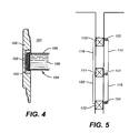
- FIG. 4 illustrates a longitudinal half-section of a controllable fluid filled bore plug
- FIG. 5 schematically illustrates several hydraulically powered well service tools in which the hydraulic conduit circulation is controlled by discretely placed magnet windings.
- the slip actuating section of a downhole tool is illustrated in schematic quarter section.
- the tool is assembled within a casement or housing pipe 10 .
- Concentrically within the casement is an internal mandrel 12 around a central fluid flow bore 14 .
- Slip wickers 17 are distributed around the mandrel circumference to overlie the ramped face 19 of an actuating cone 18 .
- the cone 18 is secured to the mandrel 12 .
- the slip wickers 17 are translated axially along the mandrel by the ram edge of a piston 16 .
- the piston 16 advances axially along the mandrel surface against the wickers 17 , the wickers slide along the face of ramp 19 for a radially outward advancement against a well bore wall or casing.
- One face of the piston 16 is a load bearing wall of a wellbore pressure chamber 32 .
- One or more flow ports 34 through the casement wall 10 keep the chamber 32 in approximate pressure equilibrium with the wellbore fluid pressure.
- the opposing face of piston 16 is a load bearing wall of the electrically controlled fluid chamber 30 .
- An orifice restrictor 42 is another load bearing wall of the controlled fluid chamber 30 and is designed to provide a precisely dimensioned orifice passageway 40 between the restrictor and the piston 16 sleeve.
- an electromagnet winding 20 Constructed into the outer perimeter of the casement 10 adjacent to the controlled fluid chamber 30 is an electromagnet winding 20 .
- the winding is energized by a battery 24 carried within the tool, usually near an axial end of the tool.
- a current controller 22 in the electromagnet power circuit comprises, for example, a signal sensor and a power switching circuit.
- the signal sensor may, for example, be responsive to a coded pulse sequence of pressure pulsations transmitted by well fluid as a carrier medium.
- the low pressure chamber 36 Opposite of the orifice 40 and restrictor 42 is a low pressure chamber 36 .
- the low pressure chamber is a void volume having capacity for the desired quantity of controlled fluid as is expected to be displaced from the chamber 30 .
- the tool is deployed with ambient pressure in the chamber 36 , there being no effort given to actively evacuate the chamber 36 .
- downhole presure may be many thousands of pounds per square inch. Consequently, relative to the downhole pressure, surface ambient pressure is extremely low.
- the winding 20 is energized to polarize the controllable fluid in the chamber 30 and prevent bypass flow into across the restriction 40 into the low pressure chamber 36 .
- the coil is de-energized thereby permitting the controllable fluid to revert to a lower-viscosity property.
- the slip actuating piston 16 displaces the controllable fluid from the chamber 30 into the low pressure chamber 36 .
- the actuating piston 16 drives the slip wicker 17 against the conical face 19 of the actuating cone 18 thereby forcing the slip wicker radially outward against the surrounding case wall.
- a selectively controlled flapper valve is represented.
- the valve body 50 surrounds a fluid flow bore 52 with a closure seat 54 .
- a flapper element 56 is pivotably secured to the housing 50 by a hinge joint 58 . Rotation of the flapper element arcs about the hinge 58 from an open flow position shown in dashed line to the flow blocking position shown in solid line as contacting the closure seat 54 .
- piston rod 53 extended from a piston element 60 .
- the piston translates within a chamber 62 .
- a coil spring 64 that biases the piston away from the hinge axes and toward the head end 66 of the chamber space.
- the head end 66 of the chamber 62 is charged with controllable fluid and surrounded by an electromagnet coil 68 .
- the piston may or mat not be perforated between the head face and rod face by selectively sized orifices that will permit the controllable fluid to flow from the head chamber 66 into the rod chamber under the displacement pressure bias of the spring 64 when the coil is de-energized.
- FIG. 3 represents another valve embodiment of the invention wherein an axially sliding sleeve element 70 is translated to a position that blocks the rotation of valve flapper 72 about the hinge axis 74 as shown by the dashed line position of the sleeve 70 .
- the valve body 76 includes a fluid pressure chamber 78 ringed by a magnet winding 80 .
- a piston 82 and integral rod 84 translates within the chamber 78 .
- the distal end of the rod 84 is channeled 86 to mesh with an operating tab 87 projecting from the locking sleeve 70 .
- a coil spring 89 bears against the distal end of the rod 84 to bias the sleeve 70 to the un-lock position.
- Opposing the bias of spring 89 is the force resultant of pressurized controllable fluid in the head chamber 90 .
- the coil 80 is energized to hold the position by substantially solidifying the ER fluid within the head chamber 90 .
- the controllable fluid pressure in the head chamber 90 may be relaxed while simultaneously holding the locking sleeve 70 in the position of blocking the rotation of flapper 72 .
- FIG. 4 illustrates a disappearing plug embodiment of the invention wherein the plug tool body 100 includes a channeled insert 102 that encompasses a fluid flow bore 101 .
- the channeled insert includes a magnet winding 103 integrated therein.
- the plug 104 comprises an outer membrane skin 106 of polymer or thin, malleable metal.
- the membrane 106 encapsulates a body of controllable fluid 108 .
- the plug 104 is positioned in the channel 102 while in the de-energized plastic state. When positioned, the magnet winding is energized to rigidify the controllable fluid 108 and hence, secure the plug at a fluid flow blocking position. At a subsequent moment when it is desired to open the flow bore 101 , the winding 103 is de-energized.
- the plug rigidity sags to facilitate removal of the plug to from the bore 101 .
- the plug remains within the fluid flow conduit, the loose, malleable nature of the de-energized may be easily accommodate by shunting or purging.
- the invention embodiment of FIG. 5 represents a series of hydraulically powered well service tools 110 , 111 and 112 .
- the power fluid pumped within the fluid circulation lines 114 , 116 , 118 and 120 is a controllable fluid.
- Magnet windings 122 , 123 and 124 are selectively positioned around the non-magnetic fluid circulation lines. When a winding is energized, the controllable fluid within the associated conduit congeals in the proximity of the winding to block fluid flow within the conduit.
- the fluid flow route through the conduits may be selectively directed or stopped.
Abstract
Description
- 1. Field of the Invention
- The present invention relates to the art of earth boring. In particular, the invention relates to methods and apparatus for remotely controlling the operation of downhole tools.
- 2. Description of Related Art
- In pursuit of deeply deposited economic minerals and fluids such as hydrocarbons, the art of earthboring involves many physical operations that are carried out remotely under hazardous and sometimes hostile conditions. For example, hydrocarbon producing boreholes may be more than. 25,000 ft. deep and have a bottom-hole pressure more than 10,000 psi and a bottom-hole temperature in excess of 300 F.
- Transmitting power and control signals to dynamic tools working near the wellbore bottom is an engineering challenge. Some tools and circumstances allow the internal flow bore of a pipe or tubing string to be pressurized with water or other well working fluid. Sustained high pressure may be used to displace sleeves or piston elements within the work string. In other circumstances, a pumped circulation flow of working fluid along the pipe bore may be used to drive a downhole fluid motor or electric generator.
- The transmission of operational commands to downhole machinery by coded sequences of pressure pulses carried along the wellbore fluid has been used to signal the beginning or ending of an operation that is mechanically executed by battery power such as the opening or closing of a valve. Also known to the prior art is the technique of using in situ wellbore pressure to power the operation of a mechanical element such a a well packer or slip.
- All of these prior art power and signal devices are useful in particular environments and applications. However, the challenges of deepwell drilling are many and diverse. New tools, procedures and downhole conditions evolve rapidly. Consequently, practitioners of the art constantly search for new and better devices and procedures to power or activate a downhole mechanism.
- “Controllable fluids” are materials that respond to an applied electric or magnetic field with a change in their rheological behavior. Typically, this change is manifested when the fluids are sheared by the development of a yield stress that is more or less proportional to the magnitude of the applied field. These materials are commonly referred to as electrorheological (ER) or magnetorheological (MR) fluids. Interest in controllable fluids derives from their ability to provide simple, quiet, rapid-response interfaces between electronic controls and mechanical systems. Controllable fluids have the potential to radically change the way electromechanical devices are designed and operated.
- MR fluids are non-colloidal suspensions of polarizable particles having a size on the order of a few microns. Typical carrier fluids for magnetically responsive particles include hydrocarbon oil, silicon oil and water. The particulates in the carrier fluid may represent 25-45% of the total mixture volume. Such fluids respond to an applied magnetic field with a change in rheological behavior. Polarization induced in the suspended particles by application of an external field causes the particles to form columnar structures parallel to the applied field. These chain-like structures restrict the motion of the fluid, thereby increasing the viscous characteristics of the suspension.
- ER systems also are non-colloidal suspensions of polarizable particles having a size on the order of a few microns. However, with applied power, some of these fluids have a volume expansion of 100%. Some formulations, properties and characteristics of controllable fluids have been provided by the authors Mark R. Jolly, Jonathan W. Bender and J. David Carlson in their publication titled Properties and Application of Commercial Magnetorheological Fluids, SPIE 5th Annual Int. Symposium on Smart Structures and Materials, San Diego, Calif., March, 1998, the body of which is incorporated herein by reference.
- It is, therefore, an object of the present invention to provide a new downhole operational tool in the form of electrically responsive polymers as active tool operation and control elements.
- Also an object of the present invention is the provision of a downhole well tool having no moving fluid control elements.
- Another object of the present invention is a disappearing flow bore plug that is electrically ejected from a flow obstruction position.
- The present invention provides a method and apparatus for actuation of a downhole tool by placing an electroactive fluid in a container within the tool where the fluid becomes either highly viscous or a solid when a small magnetic field is applied. After deactivation or removal of an electromagnetic field current, the fluid becomes much less viscous. At the lower viscosity value, the fluid may be induced to flow from a mechanical restraint chamber thereby permitting the movement of a slip setting piston. Such movement of a setting piston may be biased by a mechanical spring, by in situ wellbore pressure or by pump generated hydraulic pressure, for example.
- In another application that is similar to the first, an ER polymer is positioned to expand against setting piston elements when an electromagnetic field is imposed. The polymer expansion may be applied to displace cooperating wedge elements, for example.
- In yet another application, an MR fluid may be used to control a failsafe lock system wherein a fluid lock keeps a valve blocking element open against a mechanical spring bias until an electromagnetic power current is removed. When the current is removed and the magnetic field decreases, the MR fluid is expressed from a retention chamber under the bias of the spring to allow closure of the valve blocking element.
- Under some operational circumstances, it is necessary to temporarily but completely block the flow bore of a production tube by such means as are characterized as a “disappearing” plug. Distinctively, when the disappearing plug is removed to open the tubing flow bore, little or no structure remains in the flow bore to impede fluid flow therein. To this need, the invention provides a bore plug in the form of a thin metal or plastic container in the shape of a short cylinder, for example, filled with MR fluid. The MR fluid filled cylinder may be caged across the tubing flow bore in a retainer channel. An electromagnet coil is positioned in the proximity of the retainer channel. At the appropriate time, the coil is de-energized to reduce the MR fluid viscosity thereby collapsing from the retainer channel and from a blocking position in the tubing bore.
- An ER fluid may be used as a downhole motor or linear positioning device. Also, an ER fluid may be used as a direct wellbore packing fluid confined within a packer sleeve and electrically actuated to expand to a fluid sealing annulus barrier.
- For a thorough understanding of the present invention, reference is made to the following detailed description of the preferred embodiments, taken in conjunction with the accompanying drawing wherein:
- FIG. 1 illustrates a longitudinal half-section of a well tool actuation piston in which an MR fluid functions as a valve to release the actuating piston of a pipe slip for displacement under the drive force of in situ wellbore pressure;
- FIG. 2 illustrates a longitudinal half-section of a remotely actuated flapper valve;
- FIG. 3 illustrates a longitudinal half-section of a check valve or safety valve that is locked at an open position by a controllable fluid;
- FIG. 4 illustrates a longitudinal half-section of a controllable fluid filled bore plug; and,
- FIG. 5 schematically illustrates several hydraulically powered well service tools in which the hydraulic conduit circulation is controlled by discretely placed magnet windings.
- Referring to FIG. 1, the slip actuating section of a downhole tool is illustrated in schematic quarter section. Typically, the tool is assembled within a casement or
housing pipe 10. Concentrically within the casement is aninternal mandrel 12 around a central fluid flow bore 14.Slip wickers 17 are distributed around the mandrel circumference to overlie the rampedface 19 of anactuating cone 18. Thecone 18 is secured to themandrel 12. The slip wickers 17 are translated axially along the mandrel by the ram edge of apiston 16. As thepiston 16 advances axially along the mandrel surface against thewickers 17, the wickers slide along the face oframp 19 for a radially outward advancement against a well bore wall or casing. - One face of the
piston 16 is a load bearing wall of awellbore pressure chamber 32. One ormore flow ports 34 through thecasement wall 10 keep thechamber 32 in approximate pressure equilibrium with the wellbore fluid pressure. The opposing face ofpiston 16 is a load bearing wall of the electrically controlledfluid chamber 30. Anorifice restrictor 42 is another load bearing wall of the controlledfluid chamber 30 and is designed to provide a precisely dimensionedorifice passageway 40 between the restrictor and thepiston 16 sleeve. - Constructed into the outer perimeter of the
casement 10 adjacent to the controlledfluid chamber 30 is an electromagnet winding 20. Typically, the winding is energized by abattery 24 carried within the tool, usually near an axial end of the tool. Acurrent controller 22 in the electromagnet power circuit comprises, for example, a signal sensor and a power switching circuit. The signal sensor may, for example, be responsive to a coded pulse sequence of pressure pulsations transmitted by well fluid as a carrier medium. - Opposite of the
orifice 40 andrestrictor 42 is alow pressure chamber 36. Frequently, the low pressure chamber is a void volume having capacity for the desired quantity of controlled fluid as is expected to be displaced from thechamber 30. Often, the tool is deployed with ambient pressure in thechamber 36, there being no effort given to actively evacuate thechamber 36. However, downhole presure may be many thousands of pounds per square inch. Consequently, relative to the downhole pressure, surface ambient pressure is extremely low. - As the tool is run into a well, the winding 20 is energized to polarize the controllable fluid in the
chamber 30 and prevent bypass flow into across therestriction 40 into thelow pressure chamber 36. When situated at the desired depth, the coil is de-energized thereby permitting the controllable fluid to revert to a lower-viscosity property. Under the in situ pressure bias inchamber 32, theslip actuating piston 16 displaces the controllable fluid from thechamber 30 into thelow pressure chamber 36. In the process, theactuating piston 16 drives theslip wicker 17 against theconical face 19 of the actuatingcone 18 thereby forcing the slip wicker radially outward against the surrounding case wall. - With respect to the FIG. 2 embodiment of the invention, a selectively controlled flapper valve is represented. The
valve body 50 surrounds a fluid flow bore 52 with aclosure seat 54. Aflapper element 56 is pivotably secured to thehousing 50 by a hinge joint 58. Rotation of the flapper element arcs about thehinge 58 from an open flow position shown in dashed line to the flow blocking position shown in solid line as contacting theclosure seat 54. - Also pivotally connected to the flapper element at the hinge joint 51 is
piston rod 53 extended from apiston element 60. The piston translates within achamber 62. On the rod side of the chamber space is acoil spring 64 that biases the piston away from the hinge axes and toward thehead end 66 of the chamber space. Thehead end 66 of thechamber 62 is charged with controllable fluid and surrounded by anelectromagnet coil 68. The piston may or mat not be perforated between the head face and rod face by selectively sized orifices that will permit the controllable fluid to flow from thehead chamber 66 into the rod chamber under the displacement pressure bias of thespring 64 when the coil is de-energized. As shown with therod hinge 51 on the inside of theflapper hinge 58, advancement of thepiston 60 into thehead chamber 66 will rotate theflapper 56 away from theclosure seat 54 to open the flow bore 52. The opposite effect may be obtained by placing therod hinge 51 on the outside of theflapper hinge 58. - FIG. 3 represents another valve embodiment of the invention wherein an axially sliding sleeve element 70 is translated to a position that blocks the rotation of
valve flapper 72 about thehinge axis 74 as shown by the dashed line position of the sleeve 70. In this case, thevalve body 76 includes afluid pressure chamber 78 ringed by a magnet winding 80. Apiston 82 andintegral rod 84 translates within thechamber 78. The distal end of therod 84 is channeled 86 to mesh with anoperating tab 87 projecting from the locking sleeve 70. Acoil spring 89 bears against the distal end of therod 84 to bias the sleeve 70 to the un-lock position. Opposing the bias ofspring 89 is the force resultant of pressurized controllable fluid in thehead chamber 90. After a pumped influx of controllable fluid into thehead chamber 90 drives thepiston 82 androd 84 to the rod end of thechamber 78 against the bias ofspring 89, thecoil 80 is energized to hold the position by substantially solidifying the ER fluid within thehead chamber 90. Resultantly, the controllable fluid pressure in thehead chamber 90 may be relaxed while simultaneously holding the locking sleeve 70 in the position of blocking the rotation offlapper 72. - FIG. 4 illustrates a disappearing plug embodiment of the invention wherein the
plug tool body 100 includes a channeledinsert 102 that encompasses a fluid flow bore 101. The channeled insert includes a magnet winding 103 integrated therein. Theplug 104 comprises anouter membrane skin 106 of polymer or thin, malleable metal. Themembrane 106 encapsulates a body ofcontrollable fluid 108. Theplug 104 is positioned in thechannel 102 while in the de-energized plastic state. When positioned, the magnet winding is energized to rigidify thecontrollable fluid 108 and hence, secure the plug at a fluid flow blocking position. At a subsequent moment when it is desired to open the flow bore 101, the winding 103 is de-energized. When the magnetic field is removed from the controllable fluid, the plug rigidity sags to facilitate removal of the plug to from thebore 101. Although the plug remains within the fluid flow conduit, the loose, malleable nature of the de-energized may be easily accommodate by shunting or purging. - The invention embodiment of FIG. 5 represents a series of hydraulically powered
well service tools fluid circulation lines Magnet windings windings - Although the invention has been described in terms of specified embodiments which are set forth in detail, it should be understood that the description is for illustration only and that the invention is not necessarily limited thereto, since alternative embodiments and operating techniques will become apparent to those of ordinary skill in the art in view of the disclosure. Accordingly, modifications are contemplated which can be made without departing from the spirit of the described and claimed invention.
Claims (14)
Priority Applications (2)
| Application Number | Priority Date | Filing Date | Title |
|---|---|---|---|
| US10/444,857 US6926089B2 (en) | 2001-07-27 | 2003-05-23 | Downhole actuation system utilizing electroactive fluids |
| US10/643,030 US7823689B2 (en) | 2001-07-27 | 2003-08-18 | Closed-loop downhole resonant source |
Applications Claiming Priority (2)
| Application Number | Priority Date | Filing Date | Title |
|---|---|---|---|
| US09/916,617 US6568470B2 (en) | 2001-07-27 | 2001-07-27 | Downhole actuation system utilizing electroactive fluids |
| US10/444,857 US6926089B2 (en) | 2001-07-27 | 2003-05-23 | Downhole actuation system utilizing electroactive fluids |
Related Parent Applications (1)
| Application Number | Title | Priority Date | Filing Date |
|---|---|---|---|
| US09/916,617 Continuation US6568470B2 (en) | 2001-07-27 | 2001-07-27 | Downhole actuation system utilizing electroactive fluids |
Related Child Applications (2)
| Application Number | Title | Priority Date | Filing Date |
|---|---|---|---|
| US10/366,841 Continuation-In-Part US6795373B1 (en) | 2001-07-27 | 2003-02-14 | Permanent downhole resonant source |
| US10/643,030 Continuation-In-Part US7823689B2 (en) | 2001-07-27 | 2003-08-18 | Closed-loop downhole resonant source |
Publications (2)
| Publication Number | Publication Date |
|---|---|
| US20030192687A1 true US20030192687A1 (en) | 2003-10-16 |
| US6926089B2 US6926089B2 (en) | 2005-08-09 |
Family
ID=25437572
Family Applications (2)
| Application Number | Title | Priority Date | Filing Date |
|---|---|---|---|
| US09/916,617 Expired - Fee Related US6568470B2 (en) | 2001-07-27 | 2001-07-27 | Downhole actuation system utilizing electroactive fluids |
| US10/444,857 Expired - Fee Related US6926089B2 (en) | 2001-07-27 | 2003-05-23 | Downhole actuation system utilizing electroactive fluids |
Family Applications Before (1)
| Application Number | Title | Priority Date | Filing Date |
|---|---|---|---|
| US09/916,617 Expired - Fee Related US6568470B2 (en) | 2001-07-27 | 2001-07-27 | Downhole actuation system utilizing electroactive fluids |
Country Status (8)
| Country | Link |
|---|---|
| US (2) | US6568470B2 (en) |
| EP (1) | EP1412612B1 (en) |
| AU (1) | AU2002319608B2 (en) |
| CA (1) | CA2456189C (en) |
| DK (1) | DK200400089A (en) |
| GB (1) | GB2396178B (en) |
| NO (1) | NO334038B1 (en) |
| WO (1) | WO2003018955A1 (en) |
Cited By (21)
| Publication number | Priority date | Publication date | Assignee | Title |
|---|---|---|---|---|
| US20040112594A1 (en) * | 2001-07-27 | 2004-06-17 | Baker Hughes Incorporated | Closed-loop downhole resonant source |
| US20050087335A1 (en) * | 2002-02-19 | 2005-04-28 | Halliburton Energy Services, Inc. | Deep set safety valve |
| US20070128059A1 (en) * | 2005-12-01 | 2007-06-07 | Schlumberger Technology Corporation | Electroactive Polymer Pumping System |
| US20070193733A1 (en) * | 2006-02-21 | 2007-08-23 | Schlumberger Technology Corporation | Downhole Actuation Tools |
| US20080019852A1 (en) * | 2004-12-23 | 2008-01-24 | Jan Brand | Linear Compressor |
| US20090250206A1 (en) * | 2008-04-07 | 2009-10-08 | Baker Hughes Incorporated | Tubing pressure insensitive actuator system and method |
| WO2010065409A2 (en) * | 2008-11-25 | 2010-06-10 | Baker Hughes Incorporated | Actuator for downhole tools |
| US20100314120A1 (en) * | 2009-06-10 | 2010-12-16 | Plunkett Kevin R | Dual Acting Rod Piston Control System |
| US20110147014A1 (en) * | 2009-12-21 | 2011-06-23 | Schlumberger Technology Corporation | Control swelling of swellable packer by pre-straining the swellable packer element |
| US20110186297A1 (en) * | 2010-02-04 | 2011-08-04 | Trican Well Service Ltd. | Applications of smart fluids in well service operations |
| US8038120B2 (en) | 2006-12-29 | 2011-10-18 | Halliburton Energy Services, Inc. | Magnetically coupled safety valve with satellite outer magnets |
| US8573304B2 (en) | 2010-11-22 | 2013-11-05 | Halliburton Energy Services, Inc. | Eccentric safety valve |
| WO2014185924A1 (en) * | 2013-05-16 | 2014-11-20 | Halliburton Energy Services, Inc. | Downhole tool consistent fluid control |
| US8919730B2 (en) | 2006-12-29 | 2014-12-30 | Halliburton Energy Services, Inc. | Magnetically coupled safety valve with satellite inner magnets |
| US9097086B2 (en) | 2011-09-19 | 2015-08-04 | Saudi Arabian Oil Company | Well tractor with active traction control |
| CN105003226A (en) * | 2014-11-20 | 2015-10-28 | 中国石油化工股份有限公司 | Electric-hydraulic dual-control energy storage type fracturing well completion switch and switch control method |
| WO2016094133A1 (en) * | 2014-12-12 | 2016-06-16 | Baker Hughes Incorporated | Downhole tool actuating arrangement and method of resetting at least one downhole tool |
| WO2016200536A1 (en) * | 2015-06-12 | 2016-12-15 | Baker Hughes Incorporated | Pressure test and actuation tool and method |
| CN108571298A (en) * | 2017-03-13 | 2018-09-25 | 中国石油化工股份有限公司 | Packing device |
| US11519232B1 (en) | 2021-07-16 | 2022-12-06 | Saudi Arabian Oil Company | Methods and apparatus using modified drilling fluid with realtime tunable rheology for downhole processes |
| WO2023086240A1 (en) * | 2021-11-15 | 2023-05-19 | Baker Hughes Oilfield Operations Llc | Pressure compensator, method for pressure compensation, and system |
Families Citing this family (106)
| Publication number | Priority date | Publication date | Assignee | Title |
|---|---|---|---|---|
| US6568470B2 (en) * | 2001-07-27 | 2003-05-27 | Baker Hughes Incorporated | Downhole actuation system utilizing electroactive fluids |
| US7066064B1 (en) * | 2001-11-02 | 2006-06-27 | Varady Raymond O | Method and apparatus for vibration dampening of barfeeders |
| FR2832453B1 (en) * | 2001-11-16 | 2004-04-30 | Inst Francais Du Petrole | SYSTEM AND METHOD FOR LIMITING VORTEX-INDUCED VIBRATIONS ON AN OFFSHORE OILFIELD EXPLOITATION RISER |
| US7428922B2 (en) * | 2002-03-01 | 2008-09-30 | Halliburton Energy Services | Valve and position control using magnetorheological fluids |
| CA2425724C (en) * | 2002-04-16 | 2006-01-31 | Schlumberger Canada Limited | Tubing fill and testing valve |
| US7082078B2 (en) * | 2003-08-05 | 2006-07-25 | Halliburton Energy Services, Inc. | Magnetorheological fluid controlled mud pulser |
| US7231986B2 (en) * | 2003-09-15 | 2007-06-19 | Schlumberger Technology Corporation | Well tool protection system and method |
| US7287604B2 (en) * | 2003-09-15 | 2007-10-30 | Baker Hughes Incorporated | Steerable bit assembly and methods |
| US7219752B2 (en) | 2003-11-07 | 2007-05-22 | Aps Technologies, Inc. | System and method for damping vibration in a drill string |
| DE102004043281A1 (en) * | 2004-09-08 | 2006-03-09 | Fludicon Gmbh | Movably supported parts fixing device, has piston and cylinder between which contact area is formed and has chamber that is filled with rheologisch liquid and assigned with electrodes arrangement that causes change of properties of liquid |
| JP4513128B2 (en) * | 2004-12-28 | 2010-07-28 | 日立工機株式会社 | Pulse torque generator and power tool |
| US7341116B2 (en) * | 2005-01-20 | 2008-03-11 | Baker Hughes Incorporated | Drilling efficiency through beneficial management of rock stress levels via controlled oscillations of subterranean cutting elements |
| US7597151B2 (en) * | 2005-07-13 | 2009-10-06 | Halliburton Energy Services, Inc. | Hydraulically operated formation isolation valve for underbalanced drilling applications |
| US7559358B2 (en) * | 2005-08-03 | 2009-07-14 | Baker Hughes Incorporated | Downhole uses of electroactive polymers |
| US7337850B2 (en) * | 2005-09-14 | 2008-03-04 | Schlumberger Technology Corporation | System and method for controlling actuation of tools in a wellbore |
| US7478678B2 (en) * | 2005-12-21 | 2009-01-20 | Baker Hughes Incorporated | Time release downhole trigger |
| US8752635B2 (en) * | 2006-07-28 | 2014-06-17 | Schlumberger Technology Corporation | Downhole wet mate connection |
| US7640989B2 (en) * | 2006-08-31 | 2010-01-05 | Halliburton Energy Services, Inc. | Electrically operated well tools |
| DE102006042629A1 (en) * | 2006-09-05 | 2008-03-20 | ITT Mfg. Enterprises, Inc., Wilmington | gear lever |
| US8443875B2 (en) * | 2007-07-25 | 2013-05-21 | Smith International, Inc. | Down hole tool with adjustable fluid viscosity |
| US9163479B2 (en) * | 2007-08-03 | 2015-10-20 | Baker Hughes Incorporated | Flapper operating system without a flow tube |
| US7703532B2 (en) * | 2007-09-17 | 2010-04-27 | Baker Hughes Incorporated | Tubing retrievable injection valve |
| DE102007045110B4 (en) * | 2007-09-20 | 2010-05-20 | Inventus Engineering Gmbh | Valve for magnetorheological fluids |
| US7836975B2 (en) * | 2007-10-24 | 2010-11-23 | Schlumberger Technology Corporation | Morphable bit |
| US7779919B2 (en) * | 2008-04-23 | 2010-08-24 | Schlumberger Technology Corporation | Flapper valve retention method and system |
| US7699120B2 (en) * | 2008-07-09 | 2010-04-20 | Smith International, Inc. | On demand actuation system |
| US8327954B2 (en) | 2008-07-09 | 2012-12-11 | Smith International, Inc. | Optimized reaming system based upon weight on tool |
| US20100051517A1 (en) * | 2008-08-29 | 2010-03-04 | Schlumberger Technology Corporation | Actuation and pumping with field-responsive fluids |
| US9915138B2 (en) | 2008-09-25 | 2018-03-13 | Baker Hughes, A Ge Company, Llc | Drill bit with hydraulically adjustable axial pad for controlling torsional fluctuations |
| US7971662B2 (en) * | 2008-09-25 | 2011-07-05 | Baker Hughes Incorporated | Drill bit with adjustable steering pads |
| US8205686B2 (en) * | 2008-09-25 | 2012-06-26 | Baker Hughes Incorporated | Drill bit with adjustable axial pad for controlling torsional fluctuations |
| US8061455B2 (en) * | 2009-02-26 | 2011-11-22 | Baker Hughes Incorporated | Drill bit with adjustable cutters |
| US8087476B2 (en) * | 2009-03-05 | 2012-01-03 | Aps Technology, Inc. | System and method for damping vibration in a drill string using a magnetorheological damper |
| US9976360B2 (en) | 2009-03-05 | 2018-05-22 | Aps Technology, Inc. | System and method for damping vibration in a drill string using a magnetorheological damper |
| US8069918B2 (en) * | 2009-03-24 | 2011-12-06 | Weatherford/Lamb, Inc. | Magnetic slip retention for downhole tool |
| US8087479B2 (en) * | 2009-08-04 | 2012-01-03 | Baker Hughes Incorporated | Drill bit with an adjustable steering device |
| US8286705B2 (en) * | 2009-11-30 | 2012-10-16 | Schlumberger Technology Corporation | Apparatus and method for treating a subterranean formation using diversion |
| US8839871B2 (en) * | 2010-01-15 | 2014-09-23 | Halliburton Energy Services, Inc. | Well tools operable via thermal expansion resulting from reactive materials |
| WO2011119156A1 (en) * | 2010-03-25 | 2011-09-29 | Halliburton Energy Services, Inc. | Bi-directional flapper/sealing mechanism and technique |
| US8733448B2 (en) * | 2010-03-25 | 2014-05-27 | Halliburton Energy Services, Inc. | Electrically operated isolation valve |
| US8453748B2 (en) | 2010-03-31 | 2013-06-04 | Halliburton Energy Services, Inc. | Subterranean well valve activated with differential pressure |
| US8474533B2 (en) | 2010-12-07 | 2013-07-02 | Halliburton Energy Services, Inc. | Gas generator for pressurizing downhole samples |
| US8839873B2 (en) | 2010-12-29 | 2014-09-23 | Baker Hughes Incorporated | Isolation of zones for fracturing using removable plugs |
| CN102094596B (en) * | 2010-12-30 | 2013-08-21 | 中国海洋石油总公司 | Locking device for downhole sliding sleeve of intelligent well and operation method thereof |
| US9458679B2 (en) | 2011-03-07 | 2016-10-04 | Aps Technology, Inc. | Apparatus and method for damping vibration in a drill string |
| US8893807B2 (en) * | 2011-03-15 | 2014-11-25 | Baker Hughes Incorporated | Remote subterranean tool activation system |
| US9121250B2 (en) | 2011-03-19 | 2015-09-01 | Halliburton Energy Services, Inc. | Remotely operated isolation valve |
| CN102200006A (en) * | 2011-04-12 | 2011-09-28 | 北京师范大学 | Profile control and water plugging method for magnetic nano particles |
| US9057260B2 (en) | 2011-06-29 | 2015-06-16 | Baker Hughes Incorporated | Through tubing expandable frac sleeve with removable barrier |
| US8757274B2 (en) | 2011-07-01 | 2014-06-24 | Halliburton Energy Services, Inc. | Well tool actuator and isolation valve for use in drilling operations |
| US8646537B2 (en) * | 2011-07-11 | 2014-02-11 | Halliburton Energy Services, Inc. | Remotely activated downhole apparatus and methods |
| US8616276B2 (en) | 2011-07-11 | 2013-12-31 | Halliburton Energy Services, Inc. | Remotely activated downhole apparatus and methods |
| CN102392619B (en) * | 2011-07-21 | 2014-09-17 | 北京华油油气技术开发有限公司 | Oil tube carrying recoverable subsurface safety valve |
| US8511374B2 (en) | 2011-08-02 | 2013-08-20 | Halliburton Energy Services, Inc. | Electrically actuated insert safety valve |
| US8490687B2 (en) | 2011-08-02 | 2013-07-23 | Halliburton Energy Services, Inc. | Safety valve with provisions for powering an insert safety valve |
| US9151138B2 (en) | 2011-08-29 | 2015-10-06 | Halliburton Energy Services, Inc. | Injection of fluid into selected ones of multiple zones with well tools selectively responsive to magnetic patterns |
| US9010442B2 (en) | 2011-08-29 | 2015-04-21 | Halliburton Energy Services, Inc. | Method of completing a multi-zone fracture stimulation treatment of a wellbore |
| US9506324B2 (en) | 2012-04-05 | 2016-11-29 | Halliburton Energy Services, Inc. | Well tools selectively responsive to magnetic patterns |
| US9284801B2 (en) * | 2012-05-01 | 2016-03-15 | Packers Plus Energy Services Inc. | Actuator switch for a downhole tool, tool and method |
| EP2875332A4 (en) * | 2012-08-31 | 2016-03-16 | Halliburton Energy Services Inc | Apparatus and method for downhole in-situ determination of fluid viscosity |
| US10443378B2 (en) | 2012-08-31 | 2019-10-15 | Halliburton Energy Services, Inc. | Apparatus and method for downhole in-situ determination of fluid viscosity |
| US8899346B2 (en) | 2012-10-17 | 2014-12-02 | Halliburton Energy Services, Inc. | Perforating assembly control |
| US9169705B2 (en) | 2012-10-25 | 2015-10-27 | Halliburton Energy Services, Inc. | Pressure relief-assisted packer |
| GB2521781B (en) * | 2012-10-26 | 2019-08-07 | Halliburton Energy Services Inc | Semi-autonomous insert valve for well system |
| US9587486B2 (en) | 2013-02-28 | 2017-03-07 | Halliburton Energy Services, Inc. | Method and apparatus for magnetic pulse signature actuation |
| US9587487B2 (en) | 2013-03-12 | 2017-03-07 | Halliburton Energy Services, Inc. | Wellbore servicing tools, systems and methods utilizing near-field communication |
| US9284817B2 (en) | 2013-03-14 | 2016-03-15 | Halliburton Energy Services, Inc. | Dual magnetic sensor actuation assembly |
| US9939080B2 (en) * | 2013-04-08 | 2018-04-10 | University Of Houston | Magnetorheological fluid device |
| US20150075770A1 (en) | 2013-05-31 | 2015-03-19 | Michael Linley Fripp | Wireless activation of wellbore tools |
| US9752414B2 (en) | 2013-05-31 | 2017-09-05 | Halliburton Energy Services, Inc. | Wellbore servicing tools, systems and methods utilizing downhole wireless switches |
| US9482072B2 (en) | 2013-07-23 | 2016-11-01 | Halliburton Energy Services, Inc. | Selective electrical activation of downhole tools |
| US9739120B2 (en) | 2013-07-23 | 2017-08-22 | Halliburton Energy Services, Inc. | Electrical power storage for downhole tools |
| US9708881B2 (en) | 2013-10-07 | 2017-07-18 | Baker Hughes Incorporated | Frack plug with temporary wall support feature |
| WO2015099712A1 (en) * | 2013-12-24 | 2015-07-02 | Halliburton Energy Services, Inc. | Smart fluid completions, isolations, and safety systems |
| US9453386B2 (en) * | 2013-12-31 | 2016-09-27 | Cameron International Corporation | Magnetorheological fluid locking system |
| US10018010B2 (en) | 2014-01-24 | 2018-07-10 | Baker Hughes, A Ge Company, Llc | Disintegrating agglomerated sand frack plug |
| CN103821477B (en) * | 2014-03-17 | 2016-04-13 | 中国石油大学(华东) | Self-balancing storm valve |
| MX2016011151A (en) | 2014-03-24 | 2016-12-09 | Halliburton Energy Services Inc | Well tools having magnetic shielding for magnetic sensor. |
| US10780558B2 (en) | 2014-04-01 | 2020-09-22 | Ingersoll-Rand Industrial U.S., Inc. | Tool extensions |
| US9719316B2 (en) | 2014-04-10 | 2017-08-01 | Baker Hughes Incorporated | Relatively movable slip body and wicker for enhanced release capability |
| GB2547354B (en) | 2014-11-25 | 2021-06-23 | Halliburton Energy Services Inc | Wireless activation of wellbore tools |
| WO2016137440A1 (en) * | 2015-02-24 | 2016-09-01 | Schlumberger Canada Limited | Packer assembly with pressure dividing mechanism |
| US20160273303A1 (en) * | 2015-03-19 | 2016-09-22 | Schlumberger Technology Corporation | Actuation system with locking feature |
| US10041305B2 (en) * | 2015-09-11 | 2018-08-07 | Baker Hughes Incorporated | Actively controlled self-adjusting bits and related systems and methods |
| US10822898B2 (en) * | 2018-05-18 | 2020-11-03 | Baker Hughes, A Ge Company, Llc | Settable and unsettable device and method |
| US11542776B2 (en) | 2018-06-05 | 2023-01-03 | Halliburton Energy Services, Inc. | Method to produce a stable downhole plug with magnetorheological fluid and cement |
| BR112020026410A2 (en) | 2018-06-22 | 2021-03-23 | Schlumberger Technology B.V. | full diameter electrical flow control valve system |
| CN109695435B (en) * | 2019-02-26 | 2023-08-22 | 长江大学 | Underground safety valve and use method thereof |
| US11098463B2 (en) | 2019-11-11 | 2021-08-24 | Caterpillar Inc. | Electrically activated polymer based locking system for earth moving equipment and method |
| US11199073B2 (en) | 2020-01-31 | 2021-12-14 | Baker Hughes Oilfield Operations Llc | Plug with a resettable closure member |
| US11359456B2 (en) | 2020-01-31 | 2022-06-14 | Baker Hughes Oilfield Operations Llc | Plug with a resettable closure member |
| US11391118B2 (en) | 2020-01-31 | 2022-07-19 | Baker Hughes Oilfield Operations Llc | Plug with resettable closure member |
| US11365605B2 (en) | 2020-06-02 | 2022-06-21 | Baker Hughes Oilfield Operations Llc | Locking backpressure valve |
| US11215026B2 (en) | 2020-06-02 | 2022-01-04 | Baker Hughes Oilfield Operations Llc | Locking backpressure valve |
| US11230906B2 (en) | 2020-06-02 | 2022-01-25 | Baker Hughes Oilfield Operations Llc | Locking backpressure valve |
| US11215030B2 (en) | 2020-06-02 | 2022-01-04 | Baker Hughes Oilfield Operations Llc | Locking backpressure valve with shiftable valve seat |
| US11215028B2 (en) | 2020-06-02 | 2022-01-04 | Baker Hughes Oilfield Operations Llc | Locking backpressure valve |
| US11359460B2 (en) | 2020-06-02 | 2022-06-14 | Baker Hughes Oilfield Operations Llc | Locking backpressure valve |
| US11215031B2 (en) * | 2020-06-02 | 2022-01-04 | Baker Hughes Oilfield Operations Llc | Locking backpressure valve with shiftable valve sleeve |
| US11286747B2 (en) | 2020-08-06 | 2022-03-29 | Saudi Arabian Oil Company | Sensored electronic valve for drilling and workover applications |
| US11261679B1 (en) | 2020-08-26 | 2022-03-01 | Saudi Arabian Oil Company | Method and apparatus to cure drilling losses with an electrically triggered lost circulation material |
| CN113236146B (en) * | 2021-06-22 | 2022-03-11 | 深蓝(天津)智能制造有限责任公司 | Remote control electromagnetic energy storage release short joint |
| CN113250645B (en) * | 2021-06-22 | 2023-02-17 | 新疆华隆油田科技股份有限公司 | Piston-driven expansion packer |
| WO2023115218A1 (en) * | 2021-12-24 | 2023-06-29 | Andrew Wright | Tubing drain for tubing used with downhole pump |
| US11952861B2 (en) | 2022-03-31 | 2024-04-09 | Schlumberger Technology Corporation | Methodology and system having downhole universal actuator |
| US20230313639A1 (en) * | 2022-03-31 | 2023-10-05 | Schlumberger Technology Corporation | Methodology and system for electronic control and acquisition of downhole valve |
Citations (27)
| Publication number | Priority date | Publication date | Assignee | Title |
|---|---|---|---|---|
| US2417850A (en) * | 1942-04-14 | 1947-03-25 | Willis M Winslow | Method and means for translating electrical impulses into mechanical force |
| US2505049A (en) * | 1945-03-31 | 1950-04-25 | Linde Air Prod Co | Electric powder control |
| US2575360A (en) * | 1947-10-31 | 1951-11-20 | Rabinow Jacob | Magnetic fluid torque and force transmitting device |
| US2661825A (en) * | 1949-01-07 | 1953-12-08 | Wefco Inc | High fidelity slip control |
| US2661596A (en) * | 1950-01-28 | 1953-12-08 | Wefco Inc | Field controlled hydraulic device |
| US2663809A (en) * | 1949-01-07 | 1953-12-22 | Wefco Inc | Electric motor with a field responsive fluid clutch |
| US3047507A (en) * | 1960-04-04 | 1962-07-31 | Wefco Inc | Field responsive force transmitting compositions |
| US3659648A (en) * | 1970-12-10 | 1972-05-02 | James H Cobbs | Multi-element packer |
| US3842917A (en) * | 1971-07-16 | 1974-10-22 | Orb Inc | Pumped evacuated tube water hammer pile driver |
| US4029158A (en) * | 1974-08-09 | 1977-06-14 | Laser Engineering Development Ltd. | Pile driving apparatus |
| US4992360A (en) * | 1986-11-12 | 1991-02-12 | Konica Corporation | Silver halide light-sensitive photographic material containing a novel yellow coupler |
| US5146050A (en) * | 1989-04-25 | 1992-09-08 | Western Atlas International, Inc. | Method and apparatus for acoustic formation dip logging |
| US5158109A (en) * | 1989-04-18 | 1992-10-27 | Hare Sr Nicholas S | Electro-rheological valve |
| US5167850A (en) * | 1989-06-27 | 1992-12-01 | Trw Inc. | Fluid responsive to magnetic field |
| US5277282A (en) * | 1992-10-20 | 1994-01-11 | Kato Hatsujo Kaisha, Ltd. | Rotary oil damper |
| US5284330A (en) * | 1992-06-18 | 1994-02-08 | Lord Corporation | Magnetorheological fluid devices |
| US5291956A (en) * | 1992-04-15 | 1994-03-08 | Union Oil Company Of California | Coiled tubing drilling apparatus and method |
| US5404956A (en) * | 1993-05-07 | 1995-04-11 | Halliburton Company | Hydraulic setting tool and method of use |
| US5452745A (en) * | 1992-11-06 | 1995-09-26 | Byelocorp Scientific, Inc. | Magnetorheological valve and devices incorporating magnetorheological elements |
| US5893413A (en) * | 1996-07-16 | 1999-04-13 | Baker Hughes Incorporated | Hydrostatic tool with electrically operated setting mechanism |
| US5956951A (en) * | 1996-09-20 | 1999-09-28 | Mr Technologies | Adjustable magneto-rheological fluid device |
| US6019201A (en) * | 1996-07-30 | 2000-02-01 | Board Of Regents Of The University And Community College System Of Nevada | Magneto-rheological fluid damper |
| US6158470A (en) * | 1997-03-05 | 2000-12-12 | Lord Corporation | Two-way magnetorheological fluid valve assembly and devices utilizing same |
| US6257356B1 (en) * | 1999-10-06 | 2001-07-10 | Aps Technology, Inc. | Magnetorheological fluid apparatus, especially adapted for use in a steerable drill string, and a method of using same |
| US6433991B1 (en) * | 2000-02-02 | 2002-08-13 | Schlumberger Technology Corp. | Controlling activation of devices |
| US6568470B2 (en) * | 2001-07-27 | 2003-05-27 | Baker Hughes Incorporated | Downhole actuation system utilizing electroactive fluids |
| US6619388B2 (en) * | 2001-02-15 | 2003-09-16 | Halliburton Energy Services, Inc. | Fail safe surface controlled subsurface safety valve for use in a well |
Family Cites Families (4)
| Publication number | Priority date | Publication date | Assignee | Title |
|---|---|---|---|---|
| GB2039567B (en) * | 1979-01-16 | 1983-01-06 | Intorola Ltd | Drill spring for use in borehole drilling |
| GB2050466A (en) * | 1979-06-04 | 1981-01-07 | Intorala Ltd | Drilling jar |
| US5259487A (en) | 1992-07-14 | 1993-11-09 | The Lubrizol Corporation | Adjustable dampers using electrorheological fluids |
| US5906767A (en) | 1996-06-13 | 1999-05-25 | Lord Corporation | Magnetorheological fluid |
-
2001
- 2001-07-27 US US09/916,617 patent/US6568470B2/en not_active Expired - Fee Related
-
2002
- 2002-07-19 CA CA002456189A patent/CA2456189C/en not_active Expired - Fee Related
- 2002-07-19 EP EP02750209A patent/EP1412612B1/en not_active Expired - Lifetime
- 2002-07-19 GB GB0401938A patent/GB2396178B/en not_active Expired - Fee Related
- 2002-07-19 AU AU2002319608A patent/AU2002319608B2/en not_active Ceased
- 2002-07-19 WO PCT/US2002/023128 patent/WO2003018955A1/en not_active Application Discontinuation
-
2003
- 2003-05-23 US US10/444,857 patent/US6926089B2/en not_active Expired - Fee Related
-
2004
- 2004-01-23 DK DK200400089A patent/DK200400089A/en not_active Application Discontinuation
- 2004-01-26 NO NO20040345A patent/NO334038B1/en not_active IP Right Cessation
Patent Citations (27)
| Publication number | Priority date | Publication date | Assignee | Title |
|---|---|---|---|---|
| US2417850A (en) * | 1942-04-14 | 1947-03-25 | Willis M Winslow | Method and means for translating electrical impulses into mechanical force |
| US2505049A (en) * | 1945-03-31 | 1950-04-25 | Linde Air Prod Co | Electric powder control |
| US2575360A (en) * | 1947-10-31 | 1951-11-20 | Rabinow Jacob | Magnetic fluid torque and force transmitting device |
| US2661825A (en) * | 1949-01-07 | 1953-12-08 | Wefco Inc | High fidelity slip control |
| US2663809A (en) * | 1949-01-07 | 1953-12-22 | Wefco Inc | Electric motor with a field responsive fluid clutch |
| US2661596A (en) * | 1950-01-28 | 1953-12-08 | Wefco Inc | Field controlled hydraulic device |
| US3047507A (en) * | 1960-04-04 | 1962-07-31 | Wefco Inc | Field responsive force transmitting compositions |
| US3659648A (en) * | 1970-12-10 | 1972-05-02 | James H Cobbs | Multi-element packer |
| US3842917A (en) * | 1971-07-16 | 1974-10-22 | Orb Inc | Pumped evacuated tube water hammer pile driver |
| US4029158A (en) * | 1974-08-09 | 1977-06-14 | Laser Engineering Development Ltd. | Pile driving apparatus |
| US4992360A (en) * | 1986-11-12 | 1991-02-12 | Konica Corporation | Silver halide light-sensitive photographic material containing a novel yellow coupler |
| US5158109A (en) * | 1989-04-18 | 1992-10-27 | Hare Sr Nicholas S | Electro-rheological valve |
| US5146050A (en) * | 1989-04-25 | 1992-09-08 | Western Atlas International, Inc. | Method and apparatus for acoustic formation dip logging |
| US5167850A (en) * | 1989-06-27 | 1992-12-01 | Trw Inc. | Fluid responsive to magnetic field |
| US5291956A (en) * | 1992-04-15 | 1994-03-08 | Union Oil Company Of California | Coiled tubing drilling apparatus and method |
| US5284330A (en) * | 1992-06-18 | 1994-02-08 | Lord Corporation | Magnetorheological fluid devices |
| US5277282A (en) * | 1992-10-20 | 1994-01-11 | Kato Hatsujo Kaisha, Ltd. | Rotary oil damper |
| US5452745A (en) * | 1992-11-06 | 1995-09-26 | Byelocorp Scientific, Inc. | Magnetorheological valve and devices incorporating magnetorheological elements |
| US5404956A (en) * | 1993-05-07 | 1995-04-11 | Halliburton Company | Hydraulic setting tool and method of use |
| US5893413A (en) * | 1996-07-16 | 1999-04-13 | Baker Hughes Incorporated | Hydrostatic tool with electrically operated setting mechanism |
| US6019201A (en) * | 1996-07-30 | 2000-02-01 | Board Of Regents Of The University And Community College System Of Nevada | Magneto-rheological fluid damper |
| US5956951A (en) * | 1996-09-20 | 1999-09-28 | Mr Technologies | Adjustable magneto-rheological fluid device |
| US6158470A (en) * | 1997-03-05 | 2000-12-12 | Lord Corporation | Two-way magnetorheological fluid valve assembly and devices utilizing same |
| US6257356B1 (en) * | 1999-10-06 | 2001-07-10 | Aps Technology, Inc. | Magnetorheological fluid apparatus, especially adapted for use in a steerable drill string, and a method of using same |
| US6433991B1 (en) * | 2000-02-02 | 2002-08-13 | Schlumberger Technology Corp. | Controlling activation of devices |
| US6619388B2 (en) * | 2001-02-15 | 2003-09-16 | Halliburton Energy Services, Inc. | Fail safe surface controlled subsurface safety valve for use in a well |
| US6568470B2 (en) * | 2001-07-27 | 2003-05-27 | Baker Hughes Incorporated | Downhole actuation system utilizing electroactive fluids |
Cited By (41)
| Publication number | Priority date | Publication date | Assignee | Title |
|---|---|---|---|---|
| US7823689B2 (en) * | 2001-07-27 | 2010-11-02 | Baker Hughes Incorporated | Closed-loop downhole resonant source |
| US20040112594A1 (en) * | 2001-07-27 | 2004-06-17 | Baker Hughes Incorporated | Closed-loop downhole resonant source |
| US7434626B2 (en) | 2002-02-19 | 2008-10-14 | Halliburton Energy Services, Inc. | Deep set safety valve |
| US20070068680A1 (en) * | 2002-02-19 | 2007-03-29 | Vick James D Jr | Deep set safety valve |
| US7213653B2 (en) * | 2002-02-19 | 2007-05-08 | Halliburton Energy Services, Inc. | Deep set safety valve |
| US20050269103A1 (en) * | 2002-02-19 | 2005-12-08 | Halliburton Energy Services, Inc. | Deep set safety valve |
| US20050087335A1 (en) * | 2002-02-19 | 2005-04-28 | Halliburton Energy Services, Inc. | Deep set safety valve |
| US7624807B2 (en) * | 2002-02-19 | 2009-12-01 | Halliburton Energy Services, Inc. | Deep set safety valve |
| US20080019852A1 (en) * | 2004-12-23 | 2008-01-24 | Jan Brand | Linear Compressor |
| US20070128059A1 (en) * | 2005-12-01 | 2007-06-07 | Schlumberger Technology Corporation | Electroactive Polymer Pumping System |
| US7352111B2 (en) | 2005-12-01 | 2008-04-01 | Schlumberger Technology Corporation | Electroactive polymer pumping system |
| US20070193733A1 (en) * | 2006-02-21 | 2007-08-23 | Schlumberger Technology Corporation | Downhole Actuation Tools |
| US7562713B2 (en) | 2006-02-21 | 2009-07-21 | Schlumberger Technology Corporation | Downhole actuation tools |
| US8038120B2 (en) | 2006-12-29 | 2011-10-18 | Halliburton Energy Services, Inc. | Magnetically coupled safety valve with satellite outer magnets |
| US8919730B2 (en) | 2006-12-29 | 2014-12-30 | Halliburton Energy Services, Inc. | Magnetically coupled safety valve with satellite inner magnets |
| AU2009234075B2 (en) * | 2008-04-07 | 2014-05-01 | Baker Hughes Incorporated | A tubing pressure insensitive actuator system and method |
| US20090250206A1 (en) * | 2008-04-07 | 2009-10-08 | Baker Hughes Incorporated | Tubing pressure insensitive actuator system and method |
| US8176975B2 (en) * | 2008-04-07 | 2012-05-15 | Baker Hughes Incorporated | Tubing pressure insensitive actuator system and method |
| WO2010065409A2 (en) * | 2008-11-25 | 2010-06-10 | Baker Hughes Incorporated | Actuator for downhole tools |
| WO2010065409A3 (en) * | 2008-11-25 | 2010-08-12 | Baker Hughes Incorporated | Actuator for downhole tools |
| US8016026B2 (en) | 2008-11-25 | 2011-09-13 | Baker Hughes Incorporated | Actuator for downhole tools |
| US20100314120A1 (en) * | 2009-06-10 | 2010-12-16 | Plunkett Kevin R | Dual Acting Rod Piston Control System |
| US8261835B2 (en) * | 2009-06-10 | 2012-09-11 | Baker Hughes Incorporated | Dual acting rod piston control system |
| US20110147014A1 (en) * | 2009-12-21 | 2011-06-23 | Schlumberger Technology Corporation | Control swelling of swellable packer by pre-straining the swellable packer element |
| US8408319B2 (en) * | 2009-12-21 | 2013-04-02 | Schlumberger Technology Corporation | Control swelling of swellable packer by pre-straining the swellable packer element |
| US9206659B2 (en) * | 2010-02-04 | 2015-12-08 | Trican Well Service Ltd. | Applications of smart fluids in well service operations |
| US20110186297A1 (en) * | 2010-02-04 | 2011-08-04 | Trican Well Service Ltd. | Applications of smart fluids in well service operations |
| US8869881B2 (en) | 2010-11-22 | 2014-10-28 | Halliburton Energy Services, Inc. | Eccentric safety valve |
| US8573304B2 (en) | 2010-11-22 | 2013-11-05 | Halliburton Energy Services, Inc. | Eccentric safety valve |
| US9097086B2 (en) | 2011-09-19 | 2015-08-04 | Saudi Arabian Oil Company | Well tractor with active traction control |
| US9719325B2 (en) * | 2013-05-16 | 2017-08-01 | Halliburton Energy Services, Inc. | Downhole tool consistent fluid control |
| US20160053573A1 (en) * | 2013-05-16 | 2016-02-25 | Halliburton Energy Services, Inc. | Downhole tool consistent fluid control |
| WO2014185924A1 (en) * | 2013-05-16 | 2014-11-20 | Halliburton Energy Services, Inc. | Downhole tool consistent fluid control |
| CN105003226A (en) * | 2014-11-20 | 2015-10-28 | 中国石油化工股份有限公司 | Electric-hydraulic dual-control energy storage type fracturing well completion switch and switch control method |
| WO2016094133A1 (en) * | 2014-12-12 | 2016-06-16 | Baker Hughes Incorporated | Downhole tool actuating arrangement and method of resetting at least one downhole tool |
| WO2016200536A1 (en) * | 2015-06-12 | 2016-12-15 | Baker Hughes Incorporated | Pressure test and actuation tool and method |
| US9903196B2 (en) | 2015-06-12 | 2018-02-27 | Baker Hughes, A Ge Company, Llc | Pressure test and actuation tool and method |
| CN108571298A (en) * | 2017-03-13 | 2018-09-25 | 中国石油化工股份有限公司 | Packing device |
| US11519232B1 (en) | 2021-07-16 | 2022-12-06 | Saudi Arabian Oil Company | Methods and apparatus using modified drilling fluid with realtime tunable rheology for downhole processes |
| WO2023086240A1 (en) * | 2021-11-15 | 2023-05-19 | Baker Hughes Oilfield Operations Llc | Pressure compensator, method for pressure compensation, and system |
| US11746609B2 (en) | 2021-11-15 | 2023-09-05 | Baker Hughes Oilfield Operations Llc | Pressure compensator, method for pressure compensation, and system |
Also Published As
| Publication number | Publication date |
|---|---|
| DK200400089A (en) | 2004-01-26 |
| EP1412612B1 (en) | 2006-05-03 |
| WO2003018955A1 (en) | 2003-03-06 |
| GB0401938D0 (en) | 2004-03-03 |
| US6926089B2 (en) | 2005-08-09 |
| EP1412612A1 (en) | 2004-04-28 |
| GB2396178A (en) | 2004-06-16 |
| NO20040345L (en) | 2004-03-26 |
| CA2456189A1 (en) | 2003-03-06 |
| US20030019622A1 (en) | 2003-01-30 |
| CA2456189C (en) | 2007-06-12 |
| AU2002319608B2 (en) | 2008-01-24 |
| GB2396178B (en) | 2006-03-01 |
| NO334038B1 (en) | 2013-11-25 |
| US6568470B2 (en) | 2003-05-27 |
Similar Documents
| Publication | Publication Date | Title |
|---|---|---|
| US6568470B2 (en) | Downhole actuation system utilizing electroactive fluids | |
| AU2002319608A1 (en) | Downhole actuation system utilizing electroactive fluids | |
| US6681849B2 (en) | Downhole packer system utilizing electroactive polymers | |
| CA2614403C (en) | System and method for actuating wellbore tools | |
| US8499836B2 (en) | Electrically activating a jarring tool | |
| US8016026B2 (en) | Actuator for downhole tools | |
| US5893413A (en) | Hydrostatic tool with electrically operated setting mechanism | |
| US5070941A (en) | Downhole force generator | |
| US6779600B2 (en) | Labyrinth lock seal for hydrostatically set packer | |
| US7314091B2 (en) | Cement-through, tubing retrievable safety valve | |
| CA3041388A1 (en) | Well restimulation downhole assembly | |
| CA2564190C (en) | Hydraulically set concentric packer with multiple umbilical bypass through the piston | |
| EP2516801B1 (en) | Downhole tools with electro-mechanical and electro-hydraulic drives | |
| US6554076B2 (en) | Hydraulically activated selective circulating/reverse circulating packer assembly | |
| WO2008079992A1 (en) | Pressure-balanced choke system | |
| CA3044395A1 (en) | Perforation blocking sleeve for well restimulation | |
| US11261702B2 (en) | Downhole tool actuators and related methods for oil and gas applications | |
| AU2002329620A1 (en) | Labyrinth lock seal for hydrostatically set packer |
Legal Events
| Date | Code | Title | Description |
|---|---|---|---|
| FEPP | Fee payment procedure |
Free format text: PAYOR NUMBER ASSIGNED (ORIGINAL EVENT CODE: ASPN); ENTITY STATUS OF PATENT OWNER: LARGE ENTITY |
|
| AS | Assignment |
Owner name: BAKER HUGHES INCORPORATED, TEXAS Free format text: ASSIGNMENT OF ASSIGNORS INTEREST;ASSIGNORS:GOODSON, JAMES EDWARD JR.;CARMODY, MICHAEL;REEL/FRAME:016171/0313;SIGNING DATES FROM 20010919 TO 20010921 |
|
| FPAY | Fee payment |
Year of fee payment: 4 |
|
| FPAY | Fee payment |
Year of fee payment: 8 |
|
| REMI | Maintenance fee reminder mailed | ||
| LAPS | Lapse for failure to pay maintenance fees |
Free format text: PATENT EXPIRED FOR FAILURE TO PAY MAINTENANCE FEES (ORIGINAL EVENT CODE: EXP.) |
|
| STCH | Information on status: patent discontinuation |
Free format text: PATENT EXPIRED DUE TO NONPAYMENT OF MAINTENANCE FEES UNDER 37 CFR 1.362 |
|
| FP | Lapsed due to failure to pay maintenance fee |
Effective date: 20170809 |