US20030191416A1 - Valve sizer and method of use - Google Patents
Valve sizer and method of use Download PDFInfo
- Publication number
- US20030191416A1 US20030191416A1 US09/965,571 US96557101A US2003191416A1 US 20030191416 A1 US20030191416 A1 US 20030191416A1 US 96557101 A US96557101 A US 96557101A US 2003191416 A1 US2003191416 A1 US 2003191416A1
- Authority
- US
- United States
- Prior art keywords
- valve
- shaft
- sizer
- movable element
- valve sizer
- Prior art date
- Legal status (The legal status is an assumption and is not a legal conclusion. Google has not performed a legal analysis and makes no representation as to the accuracy of the status listed.)
- Abandoned
Links
Images


Classifications
-
- A—HUMAN NECESSITIES
- A61—MEDICAL OR VETERINARY SCIENCE; HYGIENE
- A61F—FILTERS IMPLANTABLE INTO BLOOD VESSELS; PROSTHESES; DEVICES PROVIDING PATENCY TO, OR PREVENTING COLLAPSING OF, TUBULAR STRUCTURES OF THE BODY, e.g. STENTS; ORTHOPAEDIC, NURSING OR CONTRACEPTIVE DEVICES; FOMENTATION; TREATMENT OR PROTECTION OF EYES OR EARS; BANDAGES, DRESSINGS OR ABSORBENT PADS; FIRST-AID KITS
- A61F2/00—Filters implantable into blood vessels; Prostheses, i.e. artificial substitutes or replacements for parts of the body; Appliances for connecting them with the body; Devices providing patency to, or preventing collapsing of, tubular structures of the body, e.g. stents
- A61F2/02—Prostheses implantable into the body
- A61F2/24—Heart valves ; Vascular valves, e.g. venous valves; Heart implants, e.g. passive devices for improving the function of the native valve or the heart muscle; Transmyocardial revascularisation [TMR] devices; Valves implantable in the body
- A61F2/2496—Devices for determining the dimensions of the prosthetic valve to be implanted, e.g. templates, sizers
-
- Y—GENERAL TAGGING OF NEW TECHNOLOGICAL DEVELOPMENTS; GENERAL TAGGING OF CROSS-SECTIONAL TECHNOLOGIES SPANNING OVER SEVERAL SECTIONS OF THE IPC; TECHNICAL SUBJECTS COVERED BY FORMER USPC CROSS-REFERENCE ART COLLECTIONS [XRACs] AND DIGESTS
- Y10—TECHNICAL SUBJECTS COVERED BY FORMER USPC
- Y10S—TECHNICAL SUBJECTS COVERED BY FORMER USPC CROSS-REFERENCE ART COLLECTIONS [XRACs] AND DIGESTS
- Y10S623/00—Prosthesis, i.e. artificial body members, parts thereof, or aids and accessories therefor
- Y10S623/90—Stent for heart valve
Definitions
- the present invention is directed to methods and apparatus for determining the appropriate replacement valve size when replacing a patient's cardiac valve.
- a conventional system for measuring a patient's valve annulus includes a number of varying size discs which can be attached to a rod. Each of the discs has a size which corresponds to an available valve size. The surgeon attaches one of the discs to the rod, inserts the disc into the patient's valve annulus and checks the fit of the disc within the valve annulus. If the surgeon is not satisfied with the fit, the surgeon removes the disc from the rod, attaches another disc to the rod and inserts the new disc into the valve annulus. This procedure is repeated until the surgeon is satisfied that the appropriate valve size has been identified.
- a problem with the known method and apparatus for sizing a patient's valve annulus is the time required to try a number of discs. For each valve size the surgeon tries, the surgeon must remove one of the discs and attach another one. This procedure increases the overall surgery time which increases the risk to the patient and also increases the cost of the procedure.
- the present invention solves the problems with the prior art by providing a valve sizer which is only introduced into the patient once and can identify a number of appropriate replacement valve sizes.
- the valve sizer includes an elongate shaft having a proximal end and a distal end with a movable element coupled to the distal end of the shaft.
- a valve sizing portion has an outer dimension which is at least partially defined by the movable element.
- a valve size indicator is provided at the proximal end of the shaft.
- An actuator is also provided at the proximal end for moving the movable element so that the valve sizing portion corresponds to the various valve sizes.
- the movable element includes a plurality of arms having outer surfaces generally forming a circular shape.
- a rod extends through the shaft and is operatively coupled to the actuator. The rod is rotatable relative to the shaft so that rotation of the rod moves the movable element.
- a disc is attached to the rod. The disc has a plurality of slots which receive pins attached to the plurality of arms. Camming surfaces are coupled to the shaft and configured to engage and cam the plurality of arms when the actuator is actuated to move the movable element.
- the valve sizer includes a ring mounted to and elongate shaft.
- An actuator is mounted to the proximal end of the shaft and is operatively coupled to the ring for expanding and retracting the ring.
- the ring preferably includes a first part and a second part slidably coupled to the first part. The second part is slidably received in a recess in the first part.
- Two levers are connected to the ends of the first part. One of the levers is attached to the shaft and another level is attached to a rod extending through the shaft so that rotation of the rod relative to the shaft expands and retracts the ring.
- the valve sizer has a balloon mounted to balloon may be inflated with a fluid passing through the lumen.
- the tube preferably includes a valve size indicator which indicates an outer dimension of the balloon when the balloon is inflated.
- FIG. 1 is a perspective view of a first valve sizer having arms in an expanded position.
- FIG. 2 shows the first valve sizer of FIG. 1 with the arms in a retracted position.
- FIG. 3 is an exploded perspective view of the distal end of the first valve sizer.
- FIG. 4 is a bottom perspective view of the first valve sizer with the arms in the expanded position.
- FIG. 5 is a perspective view of a second valve sizer having arms in an expanded position with a sheath exploded from the assembly for clarity.
- FIG. 6 shows the second valve sizer of FIG. 5 with the arms in a retracted position and the sheath exploded from the assembly for clarity.
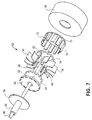
- FIG. 7 is an exploded perspective view of the distal end of the second valve sizer.
- FIG. 8 is a perspective view of a third valve sizer having an expandable ring.
- FIG. 9 shows the ring of the third valve sizer in a retracted position.
- FIG. 10 shows the ring of the third valve sizer in an expanded position.
- FIG. 11 shows a fourth valve sizer having an inflatable balloon.
- FIG. 12 is a perspective view of a fifth valve sizer.
- FIG. 13 is a partial cut-away of the distal end of the fifth valve sizer.
- FIG. 14 is a cross-sectional view of the distal end of the fifth valve sizer.
- FIGS. 1 and 2 a first valve sizer 2 is shown.
- the valve sizer 2 has a tube 4 and an actuator 6 at the proximal end of the tube 4 .
- FIG. 1 illustrates the arms 8 in an extended position
- FIG. 2 illustrates the arms 8 in a retracted position. Rotation of the actuator 6 moves the arms 8 from the retracted position to the expanded position as will be described below.
- the spacer 10 is attached to the bottom of a disc 12 which is attached to the tube 4 .
- the spacer 10 includes slots 14 which guide movement of the arms 8 between the retracted and extended positions.
- the spacer 10 includes two recesses 16 , only one of which is shown, which receive slotted discs 18 .
- the slotted discs 18 are mounted to a rod 20 which extends through the tube 4 .
- the rod 20 and tube 4 are coupled to the actuator 6 so that rotation of the actuator 6 rotates the rod 20 and slotted discs 18 with respect to the tube 4 .
- the rod 20 and slotted discs 18 form a unitary structure while the tube 4 , disc 12 and spacer 10 form another unitary structure.
- the arms 8 include pins 22 which are positioned in slots 24 of the slotted discs 18 . Rotation of the rod 20 causes the pins 22 to slide in the slots 24 of the slotted discs 18 thereby moving the arms 8 in the slots 14 of the spacer 10 between the expanded and retracted positions. Referring to FIG. 4, a bottom view is shown with the arms 8 in the expanded position.
- the arms 8 are preferably T-shaped with a curved outer surface 26 but may take any other shape.
- the outer surfaces 26 of the arms 8 generally form a circular peripheral shape when in the retracted and expanded positions.
- the outer surfaces 26 of the arms 8 define a valve sizing portion which engages the patient's valve annulus when sizing the replacement valve.
- the maximum outer dimension of the valve sizer 2 is preferably no more than 17 mm, more preferably no more than 18 mm, and most preferably no more than 19 mm, when in the retracted position.
- the outer surfaces 26 of opposing arms 8 preferably have a maximum outer dimension of at least 30 mm and more preferably at least 33 mm when in the expanded position.
- valve sizer 2 in the retracted position permits insertion of the valve sizer 2 between adjacent ribs in a patient when performing a minimally invasive valve procedure such as described in U.S. patent application Ser. No. 08/163,241 to Sterman et al., filed Dec. 6, 1993, which is incorporated herein by reference.
- the valve sizer 2 may be provided in two size ranges, preferably 17-27 mm and 23-33
- the actuator 6 includes a slot 28 with markings 30 indicating various valve sizes.
- a pointer 32 is coupled to the tube 4 an points to the marking 30 indicating the valve size corresponding to the outer dimension of the arms 8 .
- the actuator 6 is coupled to the rod 20 so that rotation of the actuator 6 causes the pointer 32 to move along the slot 28 .
- the markings 30 preferably indicate an outer diameter of 19 to 33 mm.
- any other actuation mechanism may be used including a trigger, sliding lever, or scissors-type actuator 6 .
- a method of selecting an appropriate valve size is now described with reference to FIGS. 1 - 3 .
- a method of replacing a patient's cardiac valve is described in U.S. patent application Ser. No. 08/163,241.
- the valve sizer 2 is preferably introduced into the patient between adjacent ribs in the patient without cutting or significantly deflecting the ribs.
- the valve sizer 2 is sized and configured so that it has a profile of no more than 20 mm, and more preferably no more than 19 mm, so that the valve sizer 2 may be introduced between adjacent ribs in the patient.
- the surgeon positions the arms 8 in the valve annulus and rotates the actuator 6 until the arms 8 contact the valve annulus.
- the surgeon reads the appropriate valve size with the pointer 32 and markings 30 .
- the actuator 6 is then rotated again so that the arms 8 and in the retracted position of FIG. 2 for removing the valve sizer 2 from the patient.
- valve sizer 50 includes a tube 52 having an actuator 54 at the proximal end.
- a number of arms 56 are movable from the retracted position shown of FIG. 1 to the expanded position shown in FIG. 2.
- a flexible sheath 58 is positioned around the arms 56 but is shown separated from the device for clarity.
- the sheath 58 is preferably made of silicone, however, any other suitable material may be used.
- FIG. 7 An exploded view of the distal end of the second preferred valve sizer 50 is shown in FIG. 7.
- a shaft 60 extends through the tube 52 and is connected to the actuator 54 as will be described below.
- Two discs 62 having holes 64 therein are mounted to the shaft 60 .
- the arms 56 have pins 66 which engage the holes 64 in the discs 62 so that the arms 56 are free to rotate relative to the discs 62 .
- the arms 56 are preferably curved but may take any other shape.
- the outer dimensions of the valve sizer 50 in the expanded and retracted positions are preferably the same as the first the patient's valve annulus when the actuator 54 is positioned outside the patient's chest.
- Top and bottom plates 68 , 70 are attached a sealing plate 76 which is attached to the tube 52 .
- the bottom plate 70 has a number of camming elements 72 which engage the arms 56 for moving the arms 56 from the retracted to expanded position a described below.
- the top plate 68 has openings 74 which receive the camming elements 72 .
- the top and bottom plates 68 , 70 , sealing plate 76 and tube 52 form a unitary structure.
- the top plate 68 may be omitted and the camming elements 72 may be attached directly to the sealing plate 76 .
- the camming elements 72 are positioned and configured to engage and deflect the arms 56 outward when the shaft 60 is rotated.
- the camming elements 72 are curved members but may take any other shape which cooperates with the arms 56 to cam the arms 56 outward when the shaft 60 is rotated with respect to the tube 52 .
- the valve sizer 50 may include a locking mechanism (not shown), such as a ratchet and pawl, for locking the valve sizer 50 .
- the actuator 54 may be designed with frictional resistance to turning which effectively locks the arms 56 .
- the actuator 54 has a slot 78 which receives a pointer 80 .
- the pointer 80 is coupled to the tube 52 so that the pointer 80 moves along the slot 78 when the actuator 54 is rotated.
- the actuator 54 includes markings 82 which indicate the valve size corresponding to the size defined by the outer dimension of the arms 56 and sheath 58 .
- the markings 82 preferably indicate an outer diameter of between 19 and 33 mm.
- any other actuation mechanism may be used.
- the method of using the second valve sizer 50 is the same as the first valve sizer 2 and a description of the method of use is omitted here.
- a third valve sizer 100 is shown.
- the third valve sizer 100 has a ring 102 which is movable between the retracted position of FIG. 9 to the expanded position of FIG. 10.
- An actuator 104 is mounted to the proximal end of a tube 106 and is used to move the ring 102 between the retracted and expanded positions as will be described in greater detail below.
- the ring 102 includes a first part 108 and a second part 110 slidably coupled can assume the expanded and retracted positions of FIGS. 9 and 10.
- the first part 108 has recesses 112 which are sized to slidably receive the second part 110 .
- the second part 110 includes stops 114 which prevent the first and second parts 108 , 110 from becoming detached.
- First and second levers 116 , 118 are attached to first and second ends 120 , 122 of the first part 108 , respectively.
- the first lever 116 is attached to a shaft 124 and the second lever 118 is attached to the tube 106 so that rotation of the shaft 124 relative to the tube 106 moves the first and second levers 116 , 118 with respect to one another.
- the actuator 104 has an arcuate slot 128 therein which receives a pin 130 attached to the tube 106 .
- the actuator 104 is attached to the shaft 124 so that rotation of the actuator 104 moves the first lever 116 with respect to the second lever 118 .
- the actuator 104 also preferably includes size indicators 132 which indicate the valve size corresponding to the size of the ring 102 .
- the ring 102 preferably has the same dimensions as the arms 56 of the first valve sizer when in the expanded and retracted positions.
- valve sizer 100 is introduced into the patient with the ring 102 in the retracted position of FIG. 9.
- the surgeon positions the ring 102 within the valve annulus and rotates the actuator 104 until the ring 102 engages the valve annulus.
- the surgeon then reads the indicators 132 to determine the appropriate valve size.
- the actuator 104 is rotated so that the ring 102 assumes the retracted position and the valve sizer 100 is removed from the patient.
- any other mechanism may be used including a ring 102 having teeth which engage a rotatable gear.
- the ring 102 may be a flexible ring which simply extends from the distal end of the shaft with the ring being expanded and retracted by simply lengthening or shortening the flexible ring.
- the ring 102 is preferably relatively flat, the ring 102 may be somewhat thick to form a cylinder without departing from the scope of the invention.
- a fourth preferred valve sizer 150 is shown.
- the valve sizer 150 includes a balloon 152 mounted to the distal end of a rigid tube 154 .
- a cylinder 156 is attached to the proximal end of the tube 154 and a plunger 158 having a piston 160 is slidable within the cylinder 156 .
- the tube 154 has a hole 162 through made of any conventional elastomeric material and is preferably made of polyurethan or a thermoplastic elastomer.
- the cylinder 156 is calibrated so that a given volume of fluid or gas injected into the balloon 152 expands the balloon 152 to a known size.
- the cylinder 156 preferably includes indicators 164 which indicate the valve size corresponding to the diameter of the balloon 152 .
- the balloon 152 is inflated and deflated by manipulating the plunger 158 .
- the balloon 152 preferably has a maximum outer dimension of no more than 17 mm, and more preferably no more than 19 mm, and expands to a maximum outer dimension of at least 30 mm and more preferably at least 33 mm.
- the balloon 152 is shown as being somewhat elongate the balloon 152 may also take any other shape such as a torus, sphere or any other suitable shape.
- the balloon 152 may be configured to expand from a side of the tube 154 rather than all around the tube 154 .
- tube 154 is preferably rigid, the tube 154 may be malleable to allow the tube 154 to conform to a desired shape.
- a method of using the fourth valve sizer 150 is now described.
- the balloon 152 is inserted into the patient's valve annulus in the deflated condition and the surgeon depresses the plunger 158 until the balloon 152 engages the valve annulus.
- the surgeon then reads the indicators 164 to determine the appropriate valve size.
- the balloon 152 is then deflated and the valve sizer 150 is removed from the patient.
- the fifth valve size 200 has a handle 202 from which extends a tube 204 and a shaft 206 .
- a first element 208 is attached to the tube 204 .
- a second element 210 is linearly slidable with respect to the first element 208 from the retracted solid-line position of FIG. 13 to the expanded, dotted-line position of FIG. 13.
- a pair of springs 212 bias the first and second elements 208 , 210 toward the expanded position.
- the tube 204 is attached to the first element 208 at a flange.
- the shaft 206 extends through the first element 208 toward a deflectable tongue 214 attached to the second element 210 .
- the first and second elements 208 , 210 are locked to one another by moving the shaft 206 downward into contact with first element 208 by actuating thumb switch 216 (FIG. 12) which is coupled to the shaft 206 .
- the tongue 214 is deflected downwardly by the shaft 206 into frictional together.
- the second element 210 preferably includes valve size indications 218 which indicate the valve size corresponding to the size between outer edges 220 of the first and second elements 208 , 210 .
- the fifth valve sizer 200 preferably has the same dimensions as the first valve sizer 2 when in the expanded and retracted positions. Although it is preferred to use the springs 212 and the deflectable tongue 214 to move and lock the first and second elements 208 , 210 together, it is within the scope of the invention to provide any other moving and locking mechanism.
- the fifth valve sizer 200 may include a rotatable shaft having a gear which engages a rack in the second element 210 for moving the second element 210 with respect to the first element 208 .
- a proximal size indicator could be used with the gear and rack configuration.
- valve sizer 200 is introduced into the patient's valve annulus with the first and second elements 208 , 210 in the retracted position.
- the surgeon manipulates the thumb switch 216 so that the shaft 206 moves proximally and releases the tongue 214 .
- the first and second elements 208 , 210 are then biased outwardly by the springs 212 until they contact the valve annulus.
- the surgeon manipulates the thumb switch 216 again to lock the first and second elements 208 , 210 together.
- the surgeon then removes the valve sizer 200 and reads the valve sizer indications 218 to determine the appropriate valve size.
- valve sizers are attached to shafts which do not articulate it is within the scope of the invention to provide articulating or malleable shafts so that the distal ends may be pivoted.
- valve sizers when performing a minimally invasive valve replacement procedure, the valve sizer may also be used in a conventional open-chest procedure.
Abstract
A valve sizer having a movable element mounted to the distal end of a shaft. A valve sizing portion includes the movable element so that the valve sizing portion may be adjusted to correspond to a number of different available replacement valve sizes. An indicator mounted to the proximal end of the shaft indicates the valve size corresponding to the outer dimension of the valve sizing portion.
Description
- This application is a divisional of copending U.S. patent application Ser. No 08/646,850, filed May 8, 1996.
- The present invention is directed to methods and apparatus for determining the appropriate replacement valve size when replacing a patient's cardiac valve.
- Replacement of a diseased or malfunctioning cardiac valve requires accurate sizing of the valve annulus. After the diseased or malfunctioning cardiac valve has been removed, the surgeon measures the patient's valve annulus to determine the appropriate replacement valve size.
- A conventional system for measuring a patient's valve annulus includes a number of varying size discs which can be attached to a rod. Each of the discs has a size which corresponds to an available valve size. The surgeon attaches one of the discs to the rod, inserts the disc into the patient's valve annulus and checks the fit of the disc within the valve annulus. If the surgeon is not satisfied with the fit, the surgeon removes the disc from the rod, attaches another disc to the rod and inserts the new disc into the valve annulus. This procedure is repeated until the surgeon is satisfied that the appropriate valve size has been identified.
- A problem with the known method and apparatus for sizing a patient's valve annulus is the time required to try a number of discs. For each valve size the surgeon tries, the surgeon must remove one of the discs and attach another one. This procedure increases the overall surgery time which increases the risk to the patient and also increases the cost of the procedure.
- Thus, it is a specific object of the present invention to reduce the amount of time required to size a patient's valve annulus by providing a device which can identify a number of different appropriate valve sizes without requiring withdrawal of the device from the patient.
- The present invention solves the problems with the prior art by providing a valve sizer which is only introduced into the patient once and can identify a number of appropriate replacement valve sizes. The valve sizer includes an elongate shaft having a proximal end and a distal end with a movable element coupled to the distal end of the shaft. A valve sizing portion has an outer dimension which is at least partially defined by the movable element. A valve size indicator is provided at the proximal end of the shaft. An actuator is also provided at the proximal end for moving the movable element so that the valve sizing portion corresponds to the various valve sizes.
- In a preferred embodiment, the movable element includes a plurality of arms having outer surfaces generally forming a circular shape. A rod extends through the shaft and is operatively coupled to the actuator. The rod is rotatable relative to the shaft so that rotation of the rod moves the movable element. A disc is attached to the rod. The disc has a plurality of slots which receive pins attached to the plurality of arms. Camming surfaces are coupled to the shaft and configured to engage and cam the plurality of arms when the actuator is actuated to move the movable element.
- In another preferred embodiment, the valve sizer includes a ring mounted to and elongate shaft. An actuator is mounted to the proximal end of the shaft and is operatively coupled to the ring for expanding and retracting the ring. The ring preferably includes a first part and a second part slidably coupled to the first part. The second part is slidably received in a recess in the first part. Two levers are connected to the ends of the first part. One of the levers is attached to the shaft and another level is attached to a rod extending through the shaft so that rotation of the rod relative to the shaft expands and retracts the ring.
- In yet another preferred embodiment, the valve sizer has a balloon mounted toballoon may be inflated with a fluid passing through the lumen. The tube preferably includes a valve size indicator which indicates an outer dimension of the balloon when the balloon is inflated.

- These and other features will become apparent with the following description of the preferred embodiments.
- FIG. 1 is a perspective view of a first valve sizer having arms in an expanded position.
- FIG. 2 shows the first valve sizer of FIG. 1 with the arms in a retracted position.
- FIG. 3 is an exploded perspective view of the distal end of the first valve sizer.
- FIG. 4 is a bottom perspective view of the first valve sizer with the arms in the expanded position.
- FIG. 5 is a perspective view of a second valve sizer having arms in an expanded position with a sheath exploded from the assembly for clarity.
- FIG. 6 shows the second valve sizer of FIG. 5 with the arms in a retracted position and the sheath exploded from the assembly for clarity.
- FIG. 7 is an exploded perspective view of the distal end of the second valve sizer.
- FIG. 8 is a perspective view of a third valve sizer having an expandable ring.
- FIG. 9 shows the ring of the third valve sizer in a retracted position.
- FIG. 10 shows the ring of the third valve sizer in an expanded position.
- FIG. 11 shows a fourth valve sizer having an inflatable balloon.
- FIG. 12 is a perspective view of a fifth valve sizer.
- FIG. 13 is a partial cut-away of the distal end of the fifth valve sizer.
- FIG. 14 is a cross-sectional view of the distal end of the fifth valve sizer.
- Referring to FIGS. 1 and 2, a
first valve sizer 2 is shown. Thevalve sizer 2 has atube 4 and anactuator 6 at the proximal end of thetube 4. A number ofarms 8below. FIG. 1 illustrates thearms 8 in an extended position and FIG. 2 illustrates thearms 8 in a retracted position. Rotation of theactuator 6 moves thearms 8 from the retracted position to the expanded position as will be described below. - Referring to FIG. 3, the distal end of the
valve sizer 2 is shown. Thespacer 10 is attached to the bottom of adisc 12 which is attached to thetube 4. Thespacer 10 includesslots 14 which guide movement of thearms 8 between the retracted and extended positions. Thespacer 10 includes tworecesses 16, only one of which is shown, which receiveslotted discs 18. Theslotted discs 18 are mounted to arod 20 which extends through thetube 4. As will be discussed below, therod 20 andtube 4 are coupled to theactuator 6 so that rotation of theactuator 6 rotates therod 20 and slotteddiscs 18 with respect to thetube 4. Thus, therod 20 and slotteddiscs 18 form a unitary structure while thetube 4,disc 12 andspacer 10 form another unitary structure. - The
arms 8 includepins 22 which are positioned inslots 24 of the slotteddiscs 18. Rotation of therod 20 causes thepins 22 to slide in theslots 24 of the slotteddiscs 18 thereby moving thearms 8 in theslots 14 of thespacer 10 between the expanded and retracted positions. Referring to FIG. 4, a bottom view is shown with thearms 8 in the expanded position. - The
arms 8 are preferably T-shaped with a curvedouter surface 26 but may take any other shape. Theouter surfaces 26 of thearms 8 generally form a circular peripheral shape when in the retracted and expanded positions. Theouter surfaces 26 of thearms 8 define a valve sizing portion which engages the patient's valve annulus when sizing the replacement valve. The maximum outer dimension of thevalve sizer 2 is preferably no more than 17 mm, more preferably no more than 18 mm, and most preferably no more than 19 mm, when in the retracted position. Theouter surfaces 26 of opposingarms 8 preferably have a maximum outer dimension of at least 30 mm and more preferably at least 33 mm when in the expanded position. The preferred dimensions of thevalve sizer 2 in the retracted position permits insertion of thevalve sizer 2 between adjacent ribs in a patient when performing a minimally invasive valve procedure such as described in U.S. patent application Ser. No. 08/163,241 to Sterman et al., filed Dec. 6, 1993, which is incorporated herein by reference. Alternatively, thevalve sizer 2 may be provided in two size ranges, preferably 17-27 mm and 23-33 - Referring again to FIGS. 1 and 2, the
actuator 6 includes aslot 28 withmarkings 30 indicating various valve sizes. Apointer 32 is coupled to thetube 4 an points to the marking 30 indicating the valve size corresponding to the outer dimension of thearms 8. Theactuator 6 is coupled to therod 20 so that rotation of theactuator 6 causes thepointer 32 to move along theslot 28. Themarkings 30 preferably indicate an outer diameter of 19 to 33 mm. Although it is preferred to use therotating actuator 6 to move thearms 8, any other actuation mechanism may be used including a trigger, sliding lever, or scissors-type actuator 6. - A method of selecting an appropriate valve size is now described with reference to FIGS. 1-3. A method of replacing a patient's cardiac valve is described in U.S. patent application Ser. No. 08/163,241. The
valve sizer 2 is preferably introduced into the patient between adjacent ribs in the patient without cutting or significantly deflecting the ribs. Thevalve sizer 2 is sized and configured so that it has a profile of no more than 20 mm, and more preferably no more than 19 mm, so that thevalve sizer 2 may be introduced between adjacent ribs in the patient. The surgeon then positions thearms 8 in the valve annulus and rotates theactuator 6 until thearms 8 contact the valve annulus. The surgeon then reads the appropriate valve size with thepointer 32 andmarkings 30. Theactuator 6 is then rotated again so that thearms 8 and in the retracted position of FIG. 2 for removing thevalve sizer 2 from the patient. - Referring to FIGS. 5 and 6, a second
preferred valve sizer 50 is shown. Thevalve sizer 50 includes atube 52 having an actuator 54 at the proximal end. A number ofarms 56 are movable from the retracted position shown of FIG. 1 to the expanded position shown in FIG. 2. Aflexible sheath 58 is positioned around thearms 56 but is shown separated from the device for clarity. Thesheath 58 is preferably made of silicone, however, any other suitable material may be used. - An exploded view of the distal end of the second
preferred valve sizer 50 is shown in FIG. 7. Ashaft 60 extends through thetube 52 and is connected to theactuator 54 as will be described below. Twodiscs 62 havingholes 64 therein are mounted to theshaft 60. Thearms 56 havepins 66 which engage theholes 64 in thediscs 62 so that thearms 56 are free to rotate relative to thediscs 62. Thearms 56 are preferably curved but may take any other shape. The outer dimensions of thevalve sizer 50 in the expanded and retracted positions are preferably the same as the first the patient's valve annulus when theactuator 54 is positioned outside the patient's chest. - Top and
bottom plates plate 76 which is attached to thetube 52. Thebottom plate 70 has a number ofcamming elements 72 which engage thearms 56 for moving thearms 56 from the retracted to expanded position a described below. Thetop plate 68 has openings 74 which receive thecamming elements 72. Thus, the top andbottom plates plate 76 andtube 52 form a unitary structure. Although it is preferred to provide thetop plate 68, thetop plate 68 may be omitted and thecamming elements 72 may be attached directly to the sealingplate 76. - The
camming elements 72 are positioned and configured to engage and deflect thearms 56 outward when theshaft 60 is rotated. Thecamming elements 72 are curved members but may take any other shape which cooperates with thearms 56 to cam thearms 56 outward when theshaft 60 is rotated with respect to thetube 52. Thevalve sizer 50 may include a locking mechanism (not shown), such as a ratchet and pawl, for locking thevalve sizer 50. Alternatively, theactuator 54 may be designed with frictional resistance to turning which effectively locks thearms 56. - Referring again to FIGS. 5 and 6, the
actuator 54 has aslot 78 which receives apointer 80. Thepointer 80 is coupled to thetube 52 so that thepointer 80 moves along theslot 78 when theactuator 54 is rotated. Theactuator 54 includesmarkings 82 which indicate the valve size corresponding to the size defined by the outer dimension of thearms 56 andsheath 58. Themarkings 82 preferably indicate an outer diameter of between 19 and 33 mm. Although it is preferred to use the rotatingactuator 54, any other actuation mechanism may be used. The method of using thesecond valve sizer 50 is the same as thefirst valve sizer 2 and a description of the method of use is omitted here. - Referring to FIGS. 8-10, a
third valve sizer 100 is shown. Thethird valve sizer 100 has aring 102 which is movable between the retracted position of FIG. 9 to the expanded position of FIG. 10. Anactuator 104 is mounted to the proximal end of atube 106 and is used to move thering 102 between the retracted and expanded positions as will be described in greater detail below. - The
ring 102 includes afirst part 108 and asecond part 110 slidably coupledcan assume the expanded and retracted positions of FIGS. 9 and 10. Thefirst part 108 hasrecesses 112 which are sized to slidably receive thesecond part 110. Thesecond part 110 includesstops 114 which prevent the first andsecond parts second levers first part 108, respectively. Thefirst lever 116 is attached to ashaft 124 and thesecond lever 118 is attached to thetube 106 so that rotation of theshaft 124 relative to thetube 106 moves the first andsecond levers - The
actuator 104 has an arcuate slot 128 therein which receives a pin 130 attached to thetube 106. Theactuator 104 is attached to theshaft 124 so that rotation of theactuator 104 moves thefirst lever 116 with respect to thesecond lever 118. Theactuator 104 also preferably includessize indicators 132 which indicate the valve size corresponding to the size of thering 102. Thering 102 preferably has the same dimensions as thearms 56 of the first valve sizer when in the expanded and retracted positions. - Use of the
third valve sizer 100 is now described. Thevalve sizer 100 is introduced into the patient with thering 102 in the retracted position of FIG. 9. The surgeon positions thering 102 within the valve annulus and rotates theactuator 104 until thering 102 engages the valve annulus. The surgeon then reads theindicators 132 to determine the appropriate valve size. Theactuator 104 is rotated so that thering 102 assumes the retracted position and thevalve sizer 100 is removed from the patient. Although it is preferred to provide the first andsecond levers expandable ring 102, any other mechanism may be used including aring 102 having teeth which engage a rotatable gear. Alternatively, thering 102 may be a flexible ring which simply extends from the distal end of the shaft with the ring being expanded and retracted by simply lengthening or shortening the flexible ring. Furthermore, although thering 102 is preferably relatively flat, thering 102 may be somewhat thick to form a cylinder without departing from the scope of the invention. - Referring to FIG. 11, a fourth
preferred valve sizer 150 is shown. Thevalve sizer 150 includes aballoon 152 mounted to the distal end of arigid tube 154. Acylinder 156 is attached to the proximal end of thetube 154 and aplunger 158 having apiston 160 is slidable within thecylinder 156. Thetube 154 has a hole 162 throughmade of any conventional elastomeric material and is preferably made of polyurethan or a thermoplastic elastomer. - The
cylinder 156 is calibrated so that a given volume of fluid or gas injected into theballoon 152 expands theballoon 152 to a known size. Thecylinder 156 preferably includesindicators 164 which indicate the valve size corresponding to the diameter of theballoon 152. Theballoon 152 is inflated and deflated by manipulating theplunger 158. Theballoon 152 preferably has a maximum outer dimension of no more than 17 mm, and more preferably no more than 19 mm, and expands to a maximum outer dimension of at least 30 mm and more preferably at least 33 mm. Although theballoon 152 is shown as being somewhat elongate theballoon 152 may also take any other shape such as a torus, sphere or any other suitable shape. Furthermore, although it is preferred that theballoon 152 expand around the entire periphery of the tube theballoon 152 may be configured to expand from a side of thetube 154 rather than all around thetube 154. Althoughtube 154 is preferably rigid, thetube 154 may be malleable to allow thetube 154 to conform to a desired shape. - A method of using the
fourth valve sizer 150 is now described. Theballoon 152 is inserted into the patient's valve annulus in the deflated condition and the surgeon depresses theplunger 158 until theballoon 152 engages the valve annulus. The surgeon then reads theindicators 164 to determine the appropriate valve size. Theballoon 152 is then deflated and thevalve sizer 150 is removed from the patient. - Referring to FIGS. 12-14, a
fifth valve sizer 200 is shown. Thefifth valve size 200 has ahandle 202 from which extends atube 204 and ashaft 206. Afirst element 208 is attached to thetube 204. Asecond element 210 is linearly slidable with respect to thefirst element 208 from the retracted solid-line position of FIG. 13 to the expanded, dotted-line position of FIG. 13. A pair ofsprings 212 bias the first andsecond elements - Referring to FIGS. 13 and 14 the
tube 204 is attached to thefirst element 208 at a flange. Theshaft 206 extends through thefirst element 208 toward adeflectable tongue 214 attached to thesecond element 210. The first andsecond elements shaft 206 downward into contact withfirst element 208 by actuating thumb switch 216 (FIG. 12) which is coupled to theshaft 206. Thetongue 214 is deflected downwardly by theshaft 206 into frictionaltogether. Thesecond element 210 preferably includesvalve size indications 218 which indicate the valve size corresponding to the size betweenouter edges 220 of the first andsecond elements fifth valve sizer 200 preferably has the same dimensions as thefirst valve sizer 2 when in the expanded and retracted positions. Although it is preferred to use thesprings 212 and thedeflectable tongue 214 to move and lock the first andsecond elements fifth valve sizer 200 may include a rotatable shaft having a gear which engages a rack in thesecond element 210 for moving thesecond element 210 with respect to thefirst element 208. A proximal size indicator could be used with the gear and rack configuration. - Use of the
fifth valve sizer 200 is now described. Thevalve sizer 200 is introduced into the patient's valve annulus with the first andsecond elements thumb switch 216 so that theshaft 206 moves proximally and releases thetongue 214. The first andsecond elements springs 212 until they contact the valve annulus. The surgeon then manipulates thethumb switch 216 again to lock the first andsecond elements valve sizer 200 and reads thevalve sizer indications 218 to determine the appropriate valve size. - The above description merely describes the preferred embodiments and it is understood that variations of the preferred embodiment are within the scope of the invention which is defined by the claims. For example, although the preferred valve sizers are attached to shafts which do not articulate it is within the scope of the invention to provide articulating or malleable shafts so that the distal ends may be pivoted. Furthermore, although it is preferred to use the valve sizers when performing a minimally invasive valve replacement procedure, the valve sizer may also be used in a conventional open-chest procedure.
Claims (17)
1. A valve sizer for determining an appropriate replacement valve size when performing a valve replacement procedure, comprising:
a shaft having a proximal end and a distal end;
a movable element coupled to the distal end of the shaft, the movable element being movable between a first position and a second position;
a valve sizing portion having an outer dimension, the valve sizing portion being at least partially defined by the movable element;
an indicator at the proximal end of the shaft, the indicator indicating a replacement valve size corresponding to the outer dimension of the valve sizing portion; and
an actuator at the proximal end of the elongate shaft, the actuator being operatively coupled to the movable element for moving the movable element between the first and second positions.
2. The valve sizer of claim 1 , wherein:
the movable element includes a plurality of arms, the plurality of arms having outer surfaces generally forming a generally circular shape in a plane perpendicular to a longitudinal axis defined by the shaft, the plurality of arms being movable between the first and second positions.
3. The valve sizer of claim 1 , wherein:
the plurality of arms move in a plane substantially perpendicular to a longitudinal axis defined by the shaft.
4. The valve sizer of claim 1 , further comprising:
a rod extending through at least a portion of the shaft, the rod being operatively coupled to the actuator.
5. The valve sizer of claim 4 , wherein:
the rod is rotatable relative to the shaft, the rod being coupled to the actuator so that rotation of the rod relative to the shaft moves the movable element between the first and second positions.
6. The valve sizer of claim 4 , further comprising:
a disc attached to the rod;
the movable element including a plurality of arms;
the disc having a plurality of slots which receive pins attached to the plurality of arms.
7. The valve sizer of claim 1 , further comprising:
a plurality of camming surfaces coupled to the shaft, the plurality of camming surfaces being configured to engage and cam the plurality of arms when the actuator is actuated to move the movable element from the first position to the second position.
8. The valve sizer of claim 1 , wherein:
the outer dimension is no more than 21 mm when the movable element is in the first position.
9. The valve sizer of claim 8 , wherein:
the outer dimension is no more than 19 mm when the movable element is in the first position.
10. The valve sizer of claim 8 , wherein:
the outer dimension is at least 31 mm when the movable element is in the second position.
11. The valve sizer of claim 8 , wherein:
the outer dimension is at least 33 mm when the movable element is in the second position.
12. A valve sizer for measuring a patient's valve annulus, comprising:
a shaft having a distal end and a proximal end;
a ring mounted to the distal end of the shaft, the ring being movable from a first position to a second position, the first position having a smaller diameter than the second position; and
an actuator mounted to the proximal end of the shaft, the actuator being operatively coupled to the ring for moving the ring from the first position to the second position.
13. The valve sizer of claim 12 , wherein:
the ring includes a first part and a second part slidably coupled to the first part.
14. The valve sizer of claim 12 , wherein:
the second part is slidably received in a recess in the first part, the first part having first and second ends.
15. The valve sizer of claim 14 , further comprising:
a first lever coupled to the first end of the first part;
a second lever coupled to the second end of the first part, the second lever being rotatable relative to the first lever;
the actuator being operatively coupled to at least one of the first and second levers for rotating the first lever with respect to the second lever.
16. A valve sizer for measuring a patient's valve annulus, comprising:
a shaft having a proximal end, a distal end, and an inflation lumen;
a balloon mounted to the distal end of the shaft, the balloon being fluidly coupled to the lumen; and
an indicator which indicates an outer dimension of the balloon when the balloon is inflated.
17. The valve sizer of claim 16 , further comprising:
a cylinder mounted to the proximal end of the shaft, the cylinder having a a piston slidably disposed within the cylinder;
the indicator comprising markings on the cylinder.
Priority Applications (1)
| Application Number | Priority Date | Filing Date | Title |
|---|---|---|---|
| US09/965,571 US20030191416A1 (en) | 1996-05-08 | 2001-09-27 | Valve sizer and method of use |
Applications Claiming Priority (3)
| Application Number | Priority Date | Filing Date | Title |
|---|---|---|---|
| US08/646,850 US5885228A (en) | 1996-05-08 | 1996-05-08 | Valve sizer and method of use |
| US09/514,453 US6322526B1 (en) | 1996-05-08 | 2000-02-25 | Valve sizer |
| US09/965,571 US20030191416A1 (en) | 1996-05-08 | 2001-09-27 | Valve sizer and method of use |
Related Parent Applications (1)
| Application Number | Title | Priority Date | Filing Date |
|---|---|---|---|
| US09/514,453 Continuation US6322526B1 (en) | 1996-05-08 | 2000-02-25 | Valve sizer |
Publications (1)
| Publication Number | Publication Date |
|---|---|
| US20030191416A1 true US20030191416A1 (en) | 2003-10-09 |
Family
ID=24594718
Family Applications (4)
| Application Number | Title | Priority Date | Filing Date |
|---|---|---|---|
| US08/646,850 Expired - Lifetime US5885228A (en) | 1996-05-08 | 1996-05-08 | Valve sizer and method of use |
| US09/273,955 Expired - Lifetime US6042554A (en) | 1996-05-08 | 1999-03-22 | Valve sizer and method of use |
| US09/514,453 Expired - Lifetime US6322526B1 (en) | 1996-05-08 | 2000-02-25 | Valve sizer |
| US09/965,571 Abandoned US20030191416A1 (en) | 1996-05-08 | 2001-09-27 | Valve sizer and method of use |
Family Applications Before (3)
| Application Number | Title | Priority Date | Filing Date |
|---|---|---|---|
| US08/646,850 Expired - Lifetime US5885228A (en) | 1996-05-08 | 1996-05-08 | Valve sizer and method of use |
| US09/273,955 Expired - Lifetime US6042554A (en) | 1996-05-08 | 1999-03-22 | Valve sizer and method of use |
| US09/514,453 Expired - Lifetime US6322526B1 (en) | 1996-05-08 | 2000-02-25 | Valve sizer |
Country Status (3)
| Country | Link |
|---|---|
| US (4) | US5885228A (en) |
| AU (1) | AU3061197A (en) |
| WO (1) | WO1997041801A1 (en) |
Cited By (14)
| Publication number | Priority date | Publication date | Assignee | Title |
|---|---|---|---|---|
| WO2010043982A2 (en) * | 2008-10-17 | 2010-04-22 | Edwards Lifesciences Corporation | Apparatus and method for measuring body orifice |
| US20100274159A1 (en) * | 2009-03-18 | 2010-10-28 | Contipi Ltd. | Device and method for fitting a pessary |
| WO2012106346A1 (en) * | 2011-01-31 | 2012-08-09 | St. Jude Medical, Inc. | Adjustable annuloplasty ring sizing indicator |
| WO2014210459A1 (en) * | 2013-06-28 | 2014-12-31 | Edwards Lifesciences Corporation | Covered heart valve sizer |
| US9138316B2 (en) | 2011-01-31 | 2015-09-22 | St. Jude Medical, Inc. | Adjustable annuloplasty ring sizing indicator |
| US9314336B2 (en) | 2011-01-31 | 2016-04-19 | St. Jude Medical, Inc. | Adjustment assembly for an adjustable prosthetic valve device |
| US9622860B2 (en) | 2011-01-31 | 2017-04-18 | St. Jude Medical, Inc. | Anti-rotation locking feature |
| US9763784B2 (en) | 2011-01-31 | 2017-09-19 | St. Jude Medical, Inc. | Tool for the adjustment of a prosthetic anatomical device |
| EP3243484A1 (en) * | 2015-01-06 | 2017-11-15 | Japanese Organization for Medical Device Development, Inc. | Leaflet sizer |
| US10028834B2 (en) | 2011-01-31 | 2018-07-24 | St. Jude Medical, Inc. | Adjustable prosthetic anatomical device holder and handle for the implantation of an annuloplasty ring |
| USD908874S1 (en) | 2018-07-11 | 2021-01-26 | Edwards Lifesciences Corporation | Collapsible heart valve sizer |
| US11213393B2 (en) | 2011-04-01 | 2022-01-04 | Edwards Lifesciences Corporation | Compressible heart valve annulus sizing templates |
| US11337805B2 (en) | 2018-01-23 | 2022-05-24 | Edwards Lifesciences Corporation | Prosthetic valve holders, systems, and methods |
| US11957587B2 (en) | 2021-11-08 | 2024-04-16 | Edwards Lifesciences Corporation | Protected adjustable heart valve sizer |
Families Citing this family (256)
| Publication number | Priority date | Publication date | Assignee | Title |
|---|---|---|---|---|
| US5814098A (en) * | 1995-06-07 | 1998-09-29 | St. Jude Medical, Inc. | Adjustable sizing apparatus |
| US5885228A (en) * | 1996-05-08 | 1999-03-23 | Heartport, Inc. | Valve sizer and method of use |
| US6019739A (en) * | 1998-06-18 | 2000-02-01 | Baxter International Inc. | Minimally invasive valve annulus sizer |
| US6350281B1 (en) * | 1999-09-14 | 2002-02-26 | Edwards Lifesciences Corp. | Methods and apparatus for measuring valve annuluses during heart valve-replacement surgery |
| US6491511B1 (en) | 1999-10-14 | 2002-12-10 | The International Heart Institute Of Montana Foundation | Mold to form stent-less replacement heart valves from biological membranes |
| US6678962B1 (en) * | 1999-11-17 | 2004-01-20 | Cardiomend Llc | Device and method for assessing the geometry of a heart valve |
| US6598307B2 (en) * | 1999-11-17 | 2003-07-29 | Jack W. Love | Device and method for assessing the geometry of a heart valve |
| US6679264B1 (en) | 2000-03-04 | 2004-01-20 | Emphasys Medical, Inc. | Methods and devices for use in performing pulmonary procedures |
| WO2001076468A1 (en) * | 2000-04-07 | 2001-10-18 | Conticare Medical, Inc. | Urethra sizing device |
| US8366769B2 (en) | 2000-06-01 | 2013-02-05 | Edwards Lifesciences Corporation | Low-profile, pivotable heart valve sewing ring |
| US6500132B1 (en) * | 2000-06-30 | 2002-12-31 | Sdgi Holdings, Inc. | Device and method for determining parameters of blind voids |
| CN1447669A (en) | 2000-08-18 | 2003-10-08 | 阿特里泰克公司 | Expandable implant devices for filtering blood flow from atrial appendages |
| US6893459B1 (en) * | 2000-09-20 | 2005-05-17 | Ample Medical, Inc. | Heart valve annulus device and method of using same |
| US20020133227A1 (en) * | 2001-02-28 | 2002-09-19 | Gregory Murphy | Ventricular restoration patch apparatus and method of use |
| US20030181940A1 (en) * | 2001-02-28 | 2003-09-25 | Gregory Murphy | Ventricular restoration shaping apparatus and method of use |
| US6681773B2 (en) * | 2001-02-28 | 2004-01-27 | Chase Medical, Inc. | Kit and method for use during ventricular restoration |
| US7011094B2 (en) * | 2001-03-02 | 2006-03-14 | Emphasys Medical, Inc. | Bronchial flow control devices and methods of use |
| US7798147B2 (en) * | 2001-03-02 | 2010-09-21 | Pulmonx Corporation | Bronchial flow control devices with membrane seal |
| JP4520061B2 (en) * | 2001-03-08 | 2010-08-04 | 富士通オプティカルコンポーネンツ株式会社 | Rubidium atomic oscillator |
| US20020151919A1 (en) * | 2001-04-12 | 2002-10-17 | Love Jack W. | Roller cutting device, cutting template and method for cutting tissue |
| US7935145B2 (en) | 2001-05-17 | 2011-05-03 | Edwards Lifesciences Corporation | Annuloplasty ring for ischemic mitral valve insuffuciency |
| US6908482B2 (en) | 2001-08-28 | 2005-06-21 | Edwards Lifesciences Corporation | Three-dimensional annuloplasty ring and template |
| US7485088B2 (en) * | 2001-09-05 | 2009-02-03 | Chase Medical L.P. | Method and device for percutaneous surgical ventricular repair |
| US20040243170A1 (en) * | 2001-09-05 | 2004-12-02 | Mitta Suresh | Method and device for percutaneous surgical ventricular repair |
| CA2458595C (en) * | 2001-10-11 | 2007-12-04 | Peter M. Wilson | Bronchial flow control devices and methods of use |
| US6719786B2 (en) * | 2002-03-18 | 2004-04-13 | Medtronic, Inc. | Flexible annuloplasty prosthesis and holder |
| US7160320B2 (en) * | 2002-04-16 | 2007-01-09 | The International Heart Institute Of Montana Foundation | Reed valve for implantation into mammalian blood vessels and heart with optional temporary or permanent support |
| WO2003090836A1 (en) * | 2002-04-23 | 2003-11-06 | Wilson-Cook Medical, Inc. | Precalibrated inflation device for balloon catheter |
| US20040089306A1 (en) * | 2002-05-28 | 2004-05-13 | Ronald Hundertmark | Devices and methods for removing bronchial isolation devices implanted in the lung |
| AU2003256798A1 (en) * | 2002-07-26 | 2004-02-16 | Emphasys Medical, Inc. | Bronchial flow control devices with membrane seal |
| US6966924B2 (en) * | 2002-08-16 | 2005-11-22 | St. Jude Medical, Inc. | Annuloplasty ring holder |
| US7814912B2 (en) * | 2002-11-27 | 2010-10-19 | Pulmonx Corporation | Delivery methods and devices for implantable bronchial isolation devices |
| US7717115B2 (en) * | 2002-11-27 | 2010-05-18 | Pulmonx Corporation | Delivery methods and devices for implantable bronchial isolation devices |
| US8551162B2 (en) | 2002-12-20 | 2013-10-08 | Medtronic, Inc. | Biologically implantable prosthesis |
| US7367984B2 (en) * | 2003-05-07 | 2008-05-06 | Medtronic, Inc. | Methods and apparatus for sizing fresh donor heart valves |
| US8021421B2 (en) | 2003-08-22 | 2011-09-20 | Medtronic, Inc. | Prosthesis heart valve fixturing device |
| US20050107802A1 (en) * | 2003-11-19 | 2005-05-19 | Vanasse Thomas M. | Canal sizer and associated method |
| US7748389B2 (en) * | 2003-12-23 | 2010-07-06 | Sadra Medical, Inc. | Leaflet engagement elements and methods for use thereof |
| US8828078B2 (en) | 2003-12-23 | 2014-09-09 | Sadra Medical, Inc. | Methods and apparatus for endovascular heart valve replacement comprising tissue grasping elements |
| US8287584B2 (en) * | 2005-11-14 | 2012-10-16 | Sadra Medical, Inc. | Medical implant deployment tool |
| US7959666B2 (en) | 2003-12-23 | 2011-06-14 | Sadra Medical, Inc. | Methods and apparatus for endovascularly replacing a heart valve |
| US7824442B2 (en) * | 2003-12-23 | 2010-11-02 | Sadra Medical, Inc. | Methods and apparatus for endovascularly replacing a heart valve |
| US7824443B2 (en) * | 2003-12-23 | 2010-11-02 | Sadra Medical, Inc. | Medical implant delivery and deployment tool |
| US8182528B2 (en) * | 2003-12-23 | 2012-05-22 | Sadra Medical, Inc. | Locking heart valve anchor |
| US9005273B2 (en) | 2003-12-23 | 2015-04-14 | Sadra Medical, Inc. | Assessing the location and performance of replacement heart valves |
| US20050137687A1 (en) | 2003-12-23 | 2005-06-23 | Sadra Medical | Heart valve anchor and method |
| EP2529699B1 (en) * | 2003-12-23 | 2014-01-29 | Sadra Medical, Inc. | Repositionable heart valve |
| US8579962B2 (en) | 2003-12-23 | 2013-11-12 | Sadra Medical, Inc. | Methods and apparatus for performing valvuloplasty |
| US7780725B2 (en) | 2004-06-16 | 2010-08-24 | Sadra Medical, Inc. | Everting heart valve |
| US8951299B2 (en) | 2003-12-23 | 2015-02-10 | Sadra Medical, Inc. | Medical devices and delivery systems for delivering medical devices |
| US20120041550A1 (en) | 2003-12-23 | 2012-02-16 | Sadra Medical, Inc. | Methods and Apparatus for Endovascular Heart Valve Replacement Comprising Tissue Grasping Elements |
| US8343213B2 (en) | 2003-12-23 | 2013-01-01 | Sadra Medical, Inc. | Leaflet engagement elements and methods for use thereof |
| US7381219B2 (en) | 2003-12-23 | 2008-06-03 | Sadra Medical, Inc. | Low profile heart valve and delivery system |
| US7329279B2 (en) * | 2003-12-23 | 2008-02-12 | Sadra Medical, Inc. | Methods and apparatus for endovascularly replacing a patient's heart valve |
| US7445631B2 (en) | 2003-12-23 | 2008-11-04 | Sadra Medical, Inc. | Methods and apparatus for endovascularly replacing a patient's heart valve |
| US8603160B2 (en) * | 2003-12-23 | 2013-12-10 | Sadra Medical, Inc. | Method of using a retrievable heart valve anchor with a sheath |
| US11278398B2 (en) | 2003-12-23 | 2022-03-22 | Boston Scientific Scimed, Inc. | Methods and apparatus for endovascular heart valve replacement comprising tissue grasping elements |
| US9526609B2 (en) | 2003-12-23 | 2016-12-27 | Boston Scientific Scimed, Inc. | Methods and apparatus for endovascularly replacing a patient's heart valve |
| US8840663B2 (en) | 2003-12-23 | 2014-09-23 | Sadra Medical, Inc. | Repositionable heart valve method |
| US20050137694A1 (en) | 2003-12-23 | 2005-06-23 | Haug Ulrich R. | Methods and apparatus for endovascularly replacing a patient's heart valve |
| US7871435B2 (en) | 2004-01-23 | 2011-01-18 | Edwards Lifesciences Corporation | Anatomically approximate prosthetic mitral heart valve |
| ITTO20040135A1 (en) | 2004-03-03 | 2004-06-03 | Sorin Biomedica Cardio Spa | CARDIAC VALVE PROSTHESIS |
| DE102005003632A1 (en) | 2005-01-20 | 2006-08-17 | Fraunhofer-Gesellschaft zur Förderung der angewandten Forschung e.V. | Catheter for the transvascular implantation of heart valve prostheses |
| US20060167386A1 (en) * | 2005-01-24 | 2006-07-27 | Drake Daniel H | Blood vessel graft sizer |
| ITTO20050074A1 (en) | 2005-02-10 | 2006-08-11 | Sorin Biomedica Cardio Srl | CARDIAC VALVE PROSTHESIS |
| FR2882916B1 (en) * | 2005-03-14 | 2007-06-15 | Assist Publ Hopitaux De Paris | DEVICE FOR MEASURING THE DIAMETER OF AN AORTIC PANEL |
| WO2006097931A2 (en) | 2005-03-17 | 2006-09-21 | Valtech Cardio, Ltd. | Mitral valve treatment techniques |
| US7962208B2 (en) | 2005-04-25 | 2011-06-14 | Cardiac Pacemakers, Inc. | Method and apparatus for pacing during revascularization |
| CN101180010B (en) | 2005-05-24 | 2010-12-01 | 爱德华兹生命科学公司 | Rapid deployment prosthetic heart valve |
| US8951285B2 (en) | 2005-07-05 | 2015-02-10 | Mitralign, Inc. | Tissue anchor, anchoring system and methods of using the same |
| US7712606B2 (en) | 2005-09-13 | 2010-05-11 | Sadra Medical, Inc. | Two-part package for medical implant |
| EP1968492A2 (en) | 2005-12-15 | 2008-09-17 | Georgia Technology Research Corporation | Systems and methods to control the dimension of a heart valve |
| US9125742B2 (en) | 2005-12-15 | 2015-09-08 | Georgia Tech Research Foundation | Papillary muscle position control devices, systems, and methods |
| US20070213813A1 (en) | 2005-12-22 | 2007-09-13 | Symetis Sa | Stent-valves for valve replacement and associated methods and systems for surgery |
| EP1988851A2 (en) | 2006-02-14 | 2008-11-12 | Sadra Medical, Inc. | Systems and methods for delivering a medical implant |
| WO2007100846A2 (en) * | 2006-02-28 | 2007-09-07 | Emphasys Medical, Inc. | Endoscopic tool |
| US8142495B2 (en) | 2006-05-15 | 2012-03-27 | Edwards Lifesciences Ag | System and a method for altering the geometry of the heart |
| US8585594B2 (en) | 2006-05-24 | 2013-11-19 | Phoenix Biomedical, Inc. | Methods of assessing inner surfaces of body lumens or organs |
| US7815676B2 (en) * | 2006-07-07 | 2010-10-19 | The Cleveland Clinic Foundation | Apparatus and method for assisting in the removal of a cardiac valve |
| US7871432B2 (en) * | 2006-08-02 | 2011-01-18 | Medtronic, Inc. | Heart valve holder for use in valve implantation procedures |
| JP2010511469A (en) * | 2006-12-05 | 2010-04-15 | バルテック カーディオ,リミティド | Segmented ring placement |
| US11259924B2 (en) | 2006-12-05 | 2022-03-01 | Valtech Cardio Ltd. | Implantation of repair devices in the heart |
| US9974653B2 (en) | 2006-12-05 | 2018-05-22 | Valtech Cardio, Ltd. | Implantation of repair devices in the heart |
| US9427215B2 (en) * | 2007-02-05 | 2016-08-30 | St. Jude Medical, Cardiology Division, Inc. | Minimally invasive system for delivering and securing an annular implant |
| EP2109419B1 (en) | 2007-02-09 | 2017-01-04 | Edwards Lifesciences Corporation | Progressively sized annuloplasty rings |
| US20080208328A1 (en) * | 2007-02-23 | 2008-08-28 | Endovalve, Inc. | Systems and Methods For Placement of Valve Prosthesis System |
| US11660190B2 (en) | 2007-03-13 | 2023-05-30 | Edwards Lifesciences Corporation | Tissue anchors, systems and methods, and devices |
| US7896915B2 (en) | 2007-04-13 | 2011-03-01 | Jenavalve Technology, Inc. | Medical device for treating a heart valve insufficiency |
| DE102007018199B3 (en) * | 2007-04-16 | 2008-10-02 | Rennsteig Werkzeuge Gmbh | Measuring gauge and method for determining the diameter or the cross-sectional area of a variable in the cross-sectional shape object |
| US20080262603A1 (en) * | 2007-04-23 | 2008-10-23 | Sorin Biomedica Cardio | Prosthetic heart valve holder |
| US8006535B2 (en) | 2007-07-12 | 2011-08-30 | Sorin Biomedica Cardio S.R.L. | Expandable prosthetic valve crimping device |
| US8377117B2 (en) | 2007-09-07 | 2013-02-19 | Edwards Lifesciences Corporation | Active holder for annuloplasty ring delivery |
| US9848981B2 (en) | 2007-10-12 | 2017-12-26 | Mayo Foundation For Medical Education And Research | Expandable valve prosthesis with sealing mechanism |
| US7993395B2 (en) * | 2008-01-25 | 2011-08-09 | Medtronic, Inc. | Set of annuloplasty devices with varying anterior-posterior ratios and related methods |
| US20090192602A1 (en) * | 2008-01-25 | 2009-07-30 | Medtronic, Inc. | Deformable Sizer and Holder Devices for Minimally Invasive Cardiac Surgery |
| BR112012021347A2 (en) | 2008-02-26 | 2019-09-24 | Jenavalve Tecnology Inc | stent for positioning and anchoring a valve prosthesis at an implantation site in a patient's heart |
| US9044318B2 (en) | 2008-02-26 | 2015-06-02 | Jenavalve Technology Gmbh | Stent for the positioning and anchoring of a valvular prosthesis |
| US8382829B1 (en) | 2008-03-10 | 2013-02-26 | Mitralign, Inc. | Method to reduce mitral regurgitation by cinching the commissure of the mitral valve |
| US9050049B2 (en) * | 2008-06-12 | 2015-06-09 | Daniel David Ryan | Urethra gauge and methods of manufacture, and operation thereof |
| EP2296744B1 (en) | 2008-06-16 | 2019-07-31 | Valtech Cardio, Ltd. | Annuloplasty devices |
| CN102223910B (en) | 2008-11-25 | 2014-05-07 | 爱德华兹生命科学公司 | Apparatus for in situ expansion of prosthetic device |
| US8317696B2 (en) * | 2008-12-15 | 2012-11-27 | Coroneo, Inc. | Surgical tool for measurement of valve annulus and cusp geometry |
| US8308798B2 (en) | 2008-12-19 | 2012-11-13 | Edwards Lifesciences Corporation | Quick-connect prosthetic heart valve and methods |
| US9011530B2 (en) | 2008-12-22 | 2015-04-21 | Valtech Cardio, Ltd. | Partially-adjustable annuloplasty structure |
| US10517719B2 (en) | 2008-12-22 | 2019-12-31 | Valtech Cardio, Ltd. | Implantation of repair devices in the heart |
| US8241351B2 (en) | 2008-12-22 | 2012-08-14 | Valtech Cardio, Ltd. | Adjustable partial annuloplasty ring and mechanism therefor |
| US8545553B2 (en) | 2009-05-04 | 2013-10-01 | Valtech Cardio, Ltd. | Over-wire rotation tool |
| US8715342B2 (en) | 2009-05-07 | 2014-05-06 | Valtech Cardio, Ltd. | Annuloplasty ring with intra-ring anchoring |
| CN102341063B (en) | 2008-12-22 | 2015-11-25 | 瓦尔泰克卡迪欧有限公司 | Adjustable annuloplasty device and governor motion thereof |
| US8834563B2 (en) | 2008-12-23 | 2014-09-16 | Sorin Group Italia S.R.L. | Expandable prosthetic valve having anchoring appendages |
| US8353956B2 (en) | 2009-02-17 | 2013-01-15 | Valtech Cardio, Ltd. | Actively-engageable movement-restriction mechanism for use with an annuloplasty structure |
| US8715207B2 (en) | 2009-03-19 | 2014-05-06 | Sorin Group Italia S.R.L. | Universal valve annulus sizing device |
| WO2010111621A1 (en) | 2009-03-26 | 2010-09-30 | Sorin Group Usa, Inc. | Annuloplasty sizers for minimally invasive procedures |
| US9980818B2 (en) | 2009-03-31 | 2018-05-29 | Edwards Lifesciences Corporation | Prosthetic heart valve system with positioning markers |
| US9968452B2 (en) | 2009-05-04 | 2018-05-15 | Valtech Cardio, Ltd. | Annuloplasty ring delivery cathethers |
| US8348998B2 (en) | 2009-06-26 | 2013-01-08 | Edwards Lifesciences Corporation | Unitary quick connect prosthetic heart valve and deployment system and methods |
| US20110022165A1 (en) | 2009-07-23 | 2011-01-27 | Edwards Lifesciences Corporation | Introducer for prosthetic heart valve |
| US9011520B2 (en) | 2009-10-29 | 2015-04-21 | Valtech Cardio, Ltd. | Tissue anchor for annuloplasty device |
| US9180007B2 (en) | 2009-10-29 | 2015-11-10 | Valtech Cardio, Ltd. | Apparatus and method for guide-wire based advancement of an adjustable implant |
| US10098737B2 (en) | 2009-10-29 | 2018-10-16 | Valtech Cardio, Ltd. | Tissue anchor for annuloplasty device |
| US8734467B2 (en) | 2009-12-02 | 2014-05-27 | Valtech Cardio, Ltd. | Delivery tool for implantation of spool assembly coupled to a helical anchor |
| US8870950B2 (en) | 2009-12-08 | 2014-10-28 | Mitral Tech Ltd. | Rotation-based anchoring of an implant |
| WO2011143238A2 (en) | 2010-05-10 | 2011-11-17 | Edwards Lifesciences Corporation | Prosthetic heart valve |
| US9554901B2 (en) | 2010-05-12 | 2017-01-31 | Edwards Lifesciences Corporation | Low gradient prosthetic heart valve |
| IT1400327B1 (en) | 2010-05-21 | 2013-05-24 | Sorin Biomedica Cardio Srl | SUPPORT DEVICE FOR VALVULAR PROSTHESIS AND CORRESPONDING CORRESPONDENT. |
| CN103002833B (en) | 2010-05-25 | 2016-05-11 | 耶拿阀门科技公司 | Artificial heart valve and comprise artificial heart valve and support through conduit carry interior prosthese |
| US11653910B2 (en) | 2010-07-21 | 2023-05-23 | Cardiovalve Ltd. | Helical anchor implantation |
| BR112013004115B1 (en) | 2010-08-24 | 2021-01-05 | Edwards Lifesciences Corporation | annuloplasty ring |
| US8641757B2 (en) | 2010-09-10 | 2014-02-04 | Edwards Lifesciences Corporation | Systems for rapidly deploying surgical heart valves |
| CN106073946B (en) | 2010-09-10 | 2022-01-04 | 西美蒂斯股份公司 | Valve replacement device, delivery device for a valve replacement device and method of producing a valve replacement device |
| US9125741B2 (en) | 2010-09-10 | 2015-09-08 | Edwards Lifesciences Corporation | Systems and methods for ensuring safe and rapid deployment of prosthetic heart valves |
| US9370418B2 (en) | 2010-09-10 | 2016-06-21 | Edwards Lifesciences Corporation | Rapidly deployable surgical heart valves |
| US8845720B2 (en) | 2010-09-27 | 2014-09-30 | Edwards Lifesciences Corporation | Prosthetic heart valve frame with flexible commissures |
| US8932350B2 (en) | 2010-11-30 | 2015-01-13 | Edwards Lifesciences Corporation | Reduced dehiscence annuloplasty ring |
| EP2486894B1 (en) | 2011-02-14 | 2021-06-09 | Sorin Group Italia S.r.l. | Sutureless anchoring device for cardiac valve prostheses |
| EP4119095A1 (en) | 2011-03-21 | 2023-01-18 | Cephea Valve Technologies, Inc. | Disk-based valve apparatus |
| EP2520251A1 (en) | 2011-05-05 | 2012-11-07 | Symetis SA | Method and Apparatus for Compressing Stent-Valves |
| US8945209B2 (en) | 2011-05-20 | 2015-02-03 | Edwards Lifesciences Corporation | Encapsulated heart valve |
| US9918840B2 (en) | 2011-06-23 | 2018-03-20 | Valtech Cardio, Ltd. | Closed band for percutaneous annuloplasty |
| US10792152B2 (en) | 2011-06-23 | 2020-10-06 | Valtech Cardio, Ltd. | Closed band for percutaneous annuloplasty |
| WO2013009975A1 (en) | 2011-07-12 | 2013-01-17 | Boston Scientific Scimed, Inc. | Coupling system for medical devices |
| US8858623B2 (en) * | 2011-11-04 | 2014-10-14 | Valtech Cardio, Ltd. | Implant having multiple rotational assemblies |
| US9724192B2 (en) | 2011-11-08 | 2017-08-08 | Valtech Cardio, Ltd. | Controlled steering functionality for implant-delivery tool |
| US9131926B2 (en) | 2011-11-10 | 2015-09-15 | Boston Scientific Scimed, Inc. | Direct connect flush system |
| US8940014B2 (en) | 2011-11-15 | 2015-01-27 | Boston Scientific Scimed, Inc. | Bond between components of a medical device |
| US8951243B2 (en) | 2011-12-03 | 2015-02-10 | Boston Scientific Scimed, Inc. | Medical device handle |
| US9345574B2 (en) | 2011-12-09 | 2016-05-24 | Edwards Lifesciences Corporation | Force-based heart valve sizer |
| US9277996B2 (en) | 2011-12-09 | 2016-03-08 | Edwards Lifesciences Corporation | Force-based heart valve sizer |
| US9277993B2 (en) | 2011-12-20 | 2016-03-08 | Boston Scientific Scimed, Inc. | Medical device delivery systems |
| US9510945B2 (en) | 2011-12-20 | 2016-12-06 | Boston Scientific Scimed Inc. | Medical device handle |
| US9078747B2 (en) | 2011-12-21 | 2015-07-14 | Edwards Lifesciences Corporation | Anchoring device for replacing or repairing a heart valve |
| US10172708B2 (en) | 2012-01-25 | 2019-01-08 | Boston Scientific Scimed, Inc. | Valve assembly with a bioabsorbable gasket and a replaceable valve implant |
| US9883941B2 (en) | 2012-06-19 | 2018-02-06 | Boston Scientific Scimed, Inc. | Replacement heart valve |
| WO2014052818A1 (en) | 2012-09-29 | 2014-04-03 | Mitralign, Inc. | Plication lock delivery system and method of use thereof |
| US10376266B2 (en) | 2012-10-23 | 2019-08-13 | Valtech Cardio, Ltd. | Percutaneous tissue anchor techniques |
| EP3730084A1 (en) | 2012-10-23 | 2020-10-28 | Valtech Cardio, Ltd. | Controlled steering functionality for implant-delivery tool |
| US9730793B2 (en) | 2012-12-06 | 2017-08-15 | Valtech Cardio, Ltd. | Techniques for guide-wire based advancement of a tool |
| US20150351906A1 (en) | 2013-01-24 | 2015-12-10 | Mitraltech Ltd. | Ventricularly-anchored prosthetic valves |
| US9724084B2 (en) | 2013-02-26 | 2017-08-08 | Mitralign, Inc. | Devices and methods for percutaneous tricuspid valve repair |
| US9149360B2 (en) | 2013-03-12 | 2015-10-06 | Edwards Lifesciences Corporation | Dynamic annuloplasty ring sizer |
| US9687346B2 (en) | 2013-03-14 | 2017-06-27 | Edwards Lifesciences Corporation | Multi-stranded heat set annuloplasty rings |
| US10449333B2 (en) | 2013-03-14 | 2019-10-22 | Valtech Cardio, Ltd. | Guidewire feeder |
| CN105283214B (en) | 2013-03-15 | 2018-10-16 | 北京泰德制药股份有限公司 | Translate conduit, system and its application method |
| CN105142574B (en) | 2013-03-15 | 2017-12-01 | 爱德华兹生命科学公司 | Band valve sustainer pipeline |
| US11007058B2 (en) | 2013-03-15 | 2021-05-18 | Edwards Lifesciences Corporation | Valved aortic conduits |
| US9788858B2 (en) | 2013-04-15 | 2017-10-17 | Transseptal Solutions Ltd. | Fossa ovalis penetration using probing elements |
| US9468527B2 (en) | 2013-06-12 | 2016-10-18 | Edwards Lifesciences Corporation | Cardiac implant with integrated suture fasteners |
| US9561103B2 (en) | 2013-07-17 | 2017-02-07 | Cephea Valve Technologies, Inc. | System and method for cardiac valve repair and replacement |
| US9919137B2 (en) | 2013-08-28 | 2018-03-20 | Edwards Lifesciences Corporation | Integrated balloon catheter inflation system |
| JP6563394B2 (en) | 2013-08-30 | 2019-08-21 | イェーナヴァルヴ テクノロジー インコーポレイテッド | Radially foldable frame for an artificial valve and method for manufacturing the frame |
| US10070857B2 (en) | 2013-08-31 | 2018-09-11 | Mitralign, Inc. | Devices and methods for locating and implanting tissue anchors at mitral valve commissure |
| CA2910602C (en) | 2013-09-20 | 2020-03-10 | Edwards Lifesciences Corporation | Heart valves with increased effective orifice area |
| US10299793B2 (en) | 2013-10-23 | 2019-05-28 | Valtech Cardio, Ltd. | Anchor magazine |
| US20150122687A1 (en) | 2013-11-06 | 2015-05-07 | Edwards Lifesciences Corporation | Bioprosthetic heart valves having adaptive seals to minimize paravalvular leakage |
| US9610162B2 (en) | 2013-12-26 | 2017-04-04 | Valtech Cardio, Ltd. | Implantation of flexible implant |
| US9549816B2 (en) | 2014-04-03 | 2017-01-24 | Edwards Lifesciences Corporation | Method for manufacturing high durability heart valve |
| US9585752B2 (en) | 2014-04-30 | 2017-03-07 | Edwards Lifesciences Corporation | Holder and deployment system for surgical heart valves |
| CA2914094C (en) | 2014-06-20 | 2021-01-05 | Edwards Lifesciences Corporation | Surgical heart valves identifiable post-implant |
| USD867594S1 (en) | 2015-06-19 | 2019-11-19 | Edwards Lifesciences Corporation | Prosthetic heart valve |
| WO2016059639A1 (en) | 2014-10-14 | 2016-04-21 | Valtech Cardio Ltd. | Leaflet-restraining techniques |
| EP3206603B1 (en) | 2014-10-14 | 2019-10-02 | Transseptal Solutions Ltd. | Fossa ovalis penetration apparatus |
| US9901445B2 (en) | 2014-11-21 | 2018-02-27 | Boston Scientific Scimed, Inc. | Valve locking mechanism |
| WO2016093877A1 (en) | 2014-12-09 | 2016-06-16 | Cephea Valve Technologies, Inc. | Replacement cardiac valves and methods of use and manufacture |
| US10449043B2 (en) | 2015-01-16 | 2019-10-22 | Boston Scientific Scimed, Inc. | Displacement based lock and release mechanism |
| US9861477B2 (en) | 2015-01-26 | 2018-01-09 | Boston Scientific Scimed Inc. | Prosthetic heart valve square leaflet-leaflet stitch |
| US10201417B2 (en) | 2015-02-03 | 2019-02-12 | Boston Scientific Scimed Inc. | Prosthetic heart valve having tubular seal |
| US9788942B2 (en) | 2015-02-03 | 2017-10-17 | Boston Scientific Scimed Inc. | Prosthetic heart valve having tubular seal |
| WO2016125160A1 (en) | 2015-02-05 | 2016-08-11 | Mitraltech Ltd. | Prosthetic valve with axially-sliding frames |
| US9706982B2 (en) | 2015-03-03 | 2017-07-18 | Transseptal Solutions Ltd. | Treatment of appendage openings |
| US9668674B2 (en) * | 2015-03-03 | 2017-06-06 | Transseptal Solutions Ltd. | Measurement of appendage openings |
| US20160256269A1 (en) | 2015-03-05 | 2016-09-08 | Mitralign, Inc. | Devices for treating paravalvular leakage and methods use thereof |
| US10426617B2 (en) | 2015-03-06 | 2019-10-01 | Boston Scientific Scimed, Inc. | Low profile valve locking mechanism and commissure assembly |
| US10285809B2 (en) | 2015-03-06 | 2019-05-14 | Boston Scientific Scimed Inc. | TAVI anchoring assist device |
| US10080652B2 (en) | 2015-03-13 | 2018-09-25 | Boston Scientific Scimed, Inc. | Prosthetic heart valve having an improved tubular seal |
| SG10202010021SA (en) | 2015-04-30 | 2020-11-27 | Valtech Cardio Ltd | Annuloplasty technologies |
| JP6767388B2 (en) | 2015-05-01 | 2020-10-14 | イェーナヴァルヴ テクノロジー インコーポレイテッド | Devices and methods to reduce the proportion of pacemakers in heart valve replacement |
| WO2016183523A1 (en) | 2015-05-14 | 2016-11-17 | Cephea Valve Technologies, Inc. | Cardiac valve delivery devices and systems |
| EP3294221B1 (en) | 2015-05-14 | 2024-03-06 | Cephea Valve Technologies, Inc. | Replacement mitral valves |
| US10314707B2 (en) | 2015-06-09 | 2019-06-11 | Edwards Lifesciences, Llc | Asymmetric mitral annuloplasty band |
| WO2017004374A1 (en) | 2015-07-02 | 2017-01-05 | Edwards Lifesciences Corporation | Integrated hybrid heart valves |
| US10335277B2 (en) | 2015-07-02 | 2019-07-02 | Boston Scientific Scimed Inc. | Adjustable nosecone |
| WO2017004369A1 (en) | 2015-07-02 | 2017-01-05 | Edwards Lifesciences Corporation | Hybrid heart valves adapted for post-implant expansion |
| US10195392B2 (en) | 2015-07-02 | 2019-02-05 | Boston Scientific Scimed, Inc. | Clip-on catheter |
| US10179041B2 (en) | 2015-08-12 | 2019-01-15 | Boston Scientific Scimed Icn. | Pinless release mechanism |
| US10136991B2 (en) | 2015-08-12 | 2018-11-27 | Boston Scientific Scimed Inc. | Replacement heart valve implant |
| CA2995855C (en) | 2015-09-02 | 2024-01-30 | Edwards Lifesciences Corporation | Spacer for securing a transcatheter valve to a bioprosthetic cardiac structure |
| US10779940B2 (en) | 2015-09-03 | 2020-09-22 | Boston Scientific Scimed, Inc. | Medical device handle |
| US10080653B2 (en) | 2015-09-10 | 2018-09-25 | Edwards Lifesciences Corporation | Limited expansion heart valve |
| US10398503B2 (en) | 2015-10-14 | 2019-09-03 | Transseptal Soulutions Ltd. | Fossa ovalis penetration |
| US10751182B2 (en) | 2015-12-30 | 2020-08-25 | Edwards Lifesciences Corporation | System and method for reshaping right heart |
| WO2017117370A2 (en) | 2015-12-30 | 2017-07-06 | Mitralign, Inc. | System and method for reducing tricuspid regurgitation |
| US10342660B2 (en) | 2016-02-02 | 2019-07-09 | Boston Scientific Inc. | Tensioned sheathing aids |
| US10531866B2 (en) | 2016-02-16 | 2020-01-14 | Cardiovalve Ltd. | Techniques for providing a replacement valve and transseptal communication |
| US10667904B2 (en) | 2016-03-08 | 2020-06-02 | Edwards Lifesciences Corporation | Valve implant with integrated sensor and transmitter |
| US11039926B2 (en) | 2016-03-25 | 2021-06-22 | Spiration, Inc. | Valve planning tool |
| EP4183371A1 (en) | 2016-05-13 | 2023-05-24 | JenaValve Technology, Inc. | Heart valve prosthesis delivery system and method for delivery of heart valve prosthesis with introducer sheath and loading system |
| US10245136B2 (en) | 2016-05-13 | 2019-04-02 | Boston Scientific Scimed Inc. | Containment vessel with implant sheathing guide |
| US10583005B2 (en) | 2016-05-13 | 2020-03-10 | Boston Scientific Scimed, Inc. | Medical device handle |
| US10456245B2 (en) | 2016-05-16 | 2019-10-29 | Edwards Lifesciences Corporation | System and method for applying material to a stent |
| US10201416B2 (en) | 2016-05-16 | 2019-02-12 | Boston Scientific Scimed, Inc. | Replacement heart valve implant with invertible leaflets |
| US10702274B2 (en) | 2016-05-26 | 2020-07-07 | Edwards Lifesciences Corporation | Method and system for closing left atrial appendage |
| US11331187B2 (en) | 2016-06-17 | 2022-05-17 | Cephea Valve Technologies, Inc. | Cardiac valve delivery devices and systems |
| GB201611910D0 (en) | 2016-07-08 | 2016-08-24 | Valtech Cardio Ltd | Adjustable annuloplasty device with alternating peaks and troughs |
| WO2018029680A1 (en) | 2016-08-10 | 2018-02-15 | Mitraltech Ltd. | Prosthetic valve with concentric frames |
| WO2018057482A1 (en) * | 2016-09-20 | 2018-03-29 | Terumo Cardiovascular Systems Corporation | Continuously adjustable cutting tool for preparing valve leaflet |
| USD846122S1 (en) | 2016-12-16 | 2019-04-16 | Edwards Lifesciences Corporation | Heart valve sizer |
| CA3051272C (en) | 2017-01-23 | 2023-08-22 | Cephea Valve Technologies, Inc. | Replacement mitral valves |
| AU2018203053B2 (en) | 2017-01-23 | 2020-03-05 | Cephea Valve Technologies, Inc. | Replacement mitral valves |
| WO2018138658A1 (en) | 2017-01-27 | 2018-08-02 | Jenavalve Technology, Inc. | Heart valve mimicry |
| US10463485B2 (en) | 2017-04-06 | 2019-11-05 | Edwards Lifesciences Corporation | Prosthetic valve holders with automatic deploying mechanisms |
| US11045627B2 (en) | 2017-04-18 | 2021-06-29 | Edwards Lifesciences Corporation | Catheter system with linear actuation control mechanism |
| CN110662511B (en) | 2017-04-28 | 2022-03-29 | 爱德华兹生命科学公司 | Prosthetic heart valve with collapsible retainer |
| US10828154B2 (en) | 2017-06-08 | 2020-11-10 | Boston Scientific Scimed, Inc. | Heart valve implant commissure support structure |
| CA3065329A1 (en) | 2017-06-21 | 2018-12-27 | Edwards Lifesciences Corporation | Dual-wireform limited expansion heart valves |
| WO2019028161A1 (en) | 2017-08-01 | 2019-02-07 | Boston Scientific Scimed, Inc. | Medical implant locking mechanism |
| US10939996B2 (en) | 2017-08-16 | 2021-03-09 | Boston Scientific Scimed, Inc. | Replacement heart valve commissure assembly |
| US10835221B2 (en) | 2017-11-02 | 2020-11-17 | Valtech Cardio, Ltd. | Implant-cinching devices and systems |
| US11135062B2 (en) | 2017-11-20 | 2021-10-05 | Valtech Cardio Ltd. | Cinching of dilated heart muscle |
| WO2019144071A1 (en) | 2018-01-19 | 2019-07-25 | Boston Scientific Scimed, Inc. | Medical device delivery system with feedback loop |
| WO2019144069A2 (en) | 2018-01-19 | 2019-07-25 | Boston Scientific Scimed, Inc. | Inductance mode deployment sensors for transcatheter valve system |
| WO2019145947A1 (en) | 2018-01-24 | 2019-08-01 | Valtech Cardio, Ltd. | Contraction of an annuloplasty structure |
| EP3743014B1 (en) | 2018-01-26 | 2023-07-19 | Edwards Lifesciences Innovation (Israel) Ltd. | Techniques for facilitating heart valve tethering and chord replacement |
| WO2019152727A1 (en) | 2018-02-02 | 2019-08-08 | Kalera Medical, Inc. | Devices and methods for minimally invasive kidney stone removal by combined aspiration and irrigation |
| US11147668B2 (en) | 2018-02-07 | 2021-10-19 | Boston Scientific Scimed, Inc. | Medical device delivery system with alignment feature |
| US11439732B2 (en) | 2018-02-26 | 2022-09-13 | Boston Scientific Scimed, Inc. | Embedded radiopaque marker in adaptive seal |
| US11229517B2 (en) | 2018-05-15 | 2022-01-25 | Boston Scientific Scimed, Inc. | Replacement heart valve commissure assembly |
| WO2019224577A1 (en) | 2018-05-23 | 2019-11-28 | Sorin Group Italia S.R.L. | A cardiac valve prosthesis |
| JP7170127B2 (en) | 2018-05-23 | 2022-11-11 | コーシム・ソチエタ・ア・レスポンサビリタ・リミタータ | Loading system and associated loading method for implantable prostheses |
| WO2019241477A1 (en) | 2018-06-13 | 2019-12-19 | Boston Scientific Scimed, Inc. | Replacement heart valve delivery device |
| CA3106104A1 (en) | 2018-07-12 | 2020-01-16 | Valtech Cardio, Ltd. | Annuloplasty systems and locking tools therefor |
| CN112437651B (en) | 2018-07-30 | 2024-01-16 | 爱德华兹生命科学公司 | Minimally Invasive Low Strain Annuloplasty Ring |
| US11241312B2 (en) | 2018-12-10 | 2022-02-08 | Boston Scientific Scimed, Inc. | Medical device delivery system including a resistance member |
| US11439504B2 (en) | 2019-05-10 | 2022-09-13 | Boston Scientific Scimed, Inc. | Replacement heart valve with improved cusp washout and reduced loading |
| CN110388866A (en) * | 2019-08-02 | 2019-10-29 | 云南华联锌铟股份有限公司 | A kind of crusher gape measuring device |
| WO2021084407A1 (en) | 2019-10-29 | 2021-05-06 | Valtech Cardio, Ltd. | Annuloplasty and tissue anchor technologies |
| EP4076284A1 (en) | 2019-12-16 | 2022-10-26 | Edwards Lifesciences Corporation | Valve holder assembly with suture looping protection |
Citations (1)
| Publication number | Priority date | Publication date | Assignee | Title |
|---|---|---|---|---|
| US5814098A (en) * | 1995-06-07 | 1998-09-29 | St. Jude Medical, Inc. | Adjustable sizing apparatus |
Family Cites Families (27)
| Publication number | Priority date | Publication date | Assignee | Title |
|---|---|---|---|---|
| US4016867A (en) * | 1976-04-27 | 1977-04-12 | The United States Of America As Represented By The Secretary Of The Department Of Health, Education And Welfare | Uterine caliper and depth gauge |
| US4056854A (en) * | 1976-09-28 | 1977-11-08 | The United States Of America As Represented By The Department Of Health, Education And Welfare | Aortic heart valve catheter |
| US4211241A (en) * | 1978-03-03 | 1980-07-08 | Kastec Corporation | Heart valve sizing gauge |
| CA1151862A (en) * | 1980-01-24 | 1983-08-16 | Thomas J. Fogarty | Flexible calibrator |
| US4362167A (en) * | 1981-02-06 | 1982-12-07 | Nicolai Donald R | Diagnostic measuring instrument |
| DE3230858C2 (en) * | 1982-08-19 | 1985-01-24 | Ahmadi, Ali, Dr. med., 7809 Denzlingen | Ring prosthesis |
| US4585453A (en) * | 1983-02-22 | 1986-04-29 | Shiley, Incorporated | Disposable holder for prosthetic heart valve |
| FR2543834B1 (en) * | 1983-04-07 | 1985-08-23 | Descartes Universite Rene | VARIABLE GEOMETRY PROBE FOR MEASURING RADIAL CONSTRAINTS IN A SPHINCTER OF A LIVING ORGANISM |
| DE3330921C1 (en) * | 1983-08-27 | 1985-02-07 | Karl-Heinz Dr.med. 4000 Düsseldorf Kurz | Device for determining the internal mass of hollow organs, especially the uterine cavity |
| SU1344320A1 (en) * | 1984-05-24 | 1987-10-15 | Алтайский государственный медицинский институт им.Ленинского комсомола | Measuring device |
| US5042161A (en) * | 1985-10-07 | 1991-08-27 | Joseph Hodge | Intravascular sizing method and apparatus |
| IL78177A0 (en) * | 1986-03-17 | 1986-07-31 | Yoel Ovil | Prosthetic heart valve and instrument for attaching and/or removing same |
| US4679556A (en) * | 1986-04-16 | 1987-07-14 | Shiley Inc. | Releasable holder and method of use |
| US4748982A (en) * | 1987-01-06 | 1988-06-07 | Advanced Cardiovascular Systems, Inc. | Reinforced balloon dilatation catheter with slitted exchange sleeve and method |
| US5010892A (en) * | 1988-05-04 | 1991-04-30 | Triangle Research And Development Corp. | Body lumen measuring instrument |
| US5089015A (en) * | 1989-11-28 | 1992-02-18 | Promedica International | Method for implanting unstented xenografts and allografts |
| US5053008A (en) * | 1990-11-21 | 1991-10-01 | Sandeep Bajaj | Intracardiac catheter |
| US5171248A (en) * | 1991-02-27 | 1992-12-15 | Intermedics Orthopedics, Inc. | Medullary caliper |
| EP0565648A4 (en) * | 1991-05-15 | 1994-07-06 | Bard Inc C R | Sizing balloon catheter |
| FR2681775B1 (en) * | 1991-10-01 | 1998-09-11 | Boutmy Ets | PLIERS FOR ENDOSCOPIC SURGERY WITH TILTING TOOL. |
| US5236450A (en) * | 1992-06-04 | 1993-08-17 | Carbon Implants, Inc. | Heart valve holder-rotator |
| US5471756A (en) * | 1992-12-30 | 1995-12-05 | United States Surgical Corporation | Lumen sizers |
| US5360014A (en) * | 1993-11-10 | 1994-11-01 | Carbomedics, Inc. | Sizing apparatus for heart valve with supra annular suture ring |
| US5489296A (en) * | 1993-12-17 | 1996-02-06 | Autogenics | Heart valve measurement tool |
| US5476510A (en) * | 1994-04-21 | 1995-12-19 | Medtronic, Inc. | Holder for heart valve |
| US5752522A (en) * | 1995-05-04 | 1998-05-19 | Cardiovascular Concepts, Inc. | Lesion diameter measurement catheter and method |
| US5885228A (en) * | 1996-05-08 | 1999-03-23 | Heartport, Inc. | Valve sizer and method of use |
-
1996
- 1996-05-08 US US08/646,850 patent/US5885228A/en not_active Expired - Lifetime
-
1997
- 1997-05-07 WO PCT/US1997/007782 patent/WO1997041801A1/en active Application Filing
- 1997-05-07 AU AU30611/97A patent/AU3061197A/en not_active Abandoned
-
1999
- 1999-03-22 US US09/273,955 patent/US6042554A/en not_active Expired - Lifetime
-
2000
- 2000-02-25 US US09/514,453 patent/US6322526B1/en not_active Expired - Lifetime
-
2001
- 2001-09-27 US US09/965,571 patent/US20030191416A1/en not_active Abandoned
Patent Citations (1)
| Publication number | Priority date | Publication date | Assignee | Title |
|---|---|---|---|---|
| US5814098A (en) * | 1995-06-07 | 1998-09-29 | St. Jude Medical, Inc. | Adjustable sizing apparatus |
Cited By (27)
| Publication number | Priority date | Publication date | Assignee | Title |
|---|---|---|---|---|
| WO2010043982A3 (en) * | 2008-10-17 | 2010-08-12 | Edwards Lifesciences Corporation | Apparatus and method for measuring body orifice |
| WO2010043982A2 (en) * | 2008-10-17 | 2010-04-22 | Edwards Lifesciences Corporation | Apparatus and method for measuring body orifice |
| US20100274159A1 (en) * | 2009-03-18 | 2010-10-28 | Contipi Ltd. | Device and method for fitting a pessary |
| US8728013B2 (en) * | 2009-03-18 | 2014-05-20 | Contipi Medical Ltd. | Device and method for fitting a pessary |
| US9603553B2 (en) | 2009-10-27 | 2017-03-28 | Edwards Lifesciences Corporation | Methods of measuring heart valve annuluses for valve replacement |
| US11412954B2 (en) | 2009-10-27 | 2022-08-16 | Edwards Lifesciences Corporation | Device for measuring an aortic valve annulus in an expanded condition |
| US8449625B2 (en) | 2009-10-27 | 2013-05-28 | Edwards Lifesciences Corporation | Methods of measuring heart valve annuluses for valve replacement |
| US10231646B2 (en) | 2009-10-27 | 2019-03-19 | Edwards Lifesciences Corporation | Device for measuring an aortic valve annulus in an expanded condition |
| US9622860B2 (en) | 2011-01-31 | 2017-04-18 | St. Jude Medical, Inc. | Anti-rotation locking feature |
| US9314336B2 (en) | 2011-01-31 | 2016-04-19 | St. Jude Medical, Inc. | Adjustment assembly for an adjustable prosthetic valve device |
| US9763784B2 (en) | 2011-01-31 | 2017-09-19 | St. Jude Medical, Inc. | Tool for the adjustment of a prosthetic anatomical device |
| US9138316B2 (en) | 2011-01-31 | 2015-09-22 | St. Jude Medical, Inc. | Adjustable annuloplasty ring sizing indicator |
| US10028834B2 (en) | 2011-01-31 | 2018-07-24 | St. Jude Medical, Inc. | Adjustable prosthetic anatomical device holder and handle for the implantation of an annuloplasty ring |
| US10603169B2 (en) | 2011-01-31 | 2020-03-31 | St. Jude Medical, Llc | Tool for the adjustment of a prosthetic anatomical device |
| WO2012106346A1 (en) * | 2011-01-31 | 2012-08-09 | St. Jude Medical, Inc. | Adjustable annuloplasty ring sizing indicator |
| US11213393B2 (en) | 2011-04-01 | 2022-01-04 | Edwards Lifesciences Corporation | Compressible heart valve annulus sizing templates |
| US11622861B2 (en) | 2011-04-01 | 2023-04-11 | Edwards Lifesciences Corporation | Compressible heart valve annulus sizing templates |
| US9895228B2 (en) | 2013-06-28 | 2018-02-20 | Edwards Lifesciences Corporation | Covered heart valve sizer |
| WO2014210459A1 (en) * | 2013-06-28 | 2014-12-31 | Edwards Lifesciences Corporation | Covered heart valve sizer |
| US11166819B2 (en) | 2013-06-28 | 2021-11-09 | Edwards Lifesciences Corporation | Covered heart valve sizer |
| EP3243484A1 (en) * | 2015-01-06 | 2017-11-15 | Japanese Organization for Medical Device Development, Inc. | Leaflet sizer |
| EP3243484A4 (en) * | 2015-01-06 | 2018-07-25 | Japanese Organization for Medical Device Development, Inc. | Leaflet sizer |
| US11337805B2 (en) | 2018-01-23 | 2022-05-24 | Edwards Lifesciences Corporation | Prosthetic valve holders, systems, and methods |
| USD952143S1 (en) | 2018-07-11 | 2022-05-17 | Edwards Lifesciences Corporation | Collapsible heart valve sizer |
| USD908874S1 (en) | 2018-07-11 | 2021-01-26 | Edwards Lifesciences Corporation | Collapsible heart valve sizer |
| USD995774S1 (en) | 2018-07-11 | 2023-08-15 | Edwards Lifesciences Corporation | Collapsible heart valve sizer |
| US11957587B2 (en) | 2021-11-08 | 2024-04-16 | Edwards Lifesciences Corporation | Protected adjustable heart valve sizer |
Also Published As
| Publication number | Publication date |
|---|---|
| US5885228A (en) | 1999-03-23 |
| AU3061197A (en) | 1997-11-26 |
| WO1997041801A1 (en) | 1997-11-13 |
| US6322526B1 (en) | 2001-11-27 |
| US6042554A (en) | 2000-03-28 |
Similar Documents
| Publication | Publication Date | Title |
|---|---|---|
| US6322526B1 (en) | Valve sizer | |
| US6110200A (en) | Adjustable sizing apparatus | |
| US9314282B2 (en) | Intramedullary rod instrument | |
| US5289817A (en) | Endoscopic surgical retractor | |
| US20090076607A1 (en) | Collapsible and Expandable Device and Methods of Using Same | |
| US5441044A (en) | Surgical retractor | |
| CA2061397C (en) | Locking trocar sleeve | |
| EP1410771B1 (en) | Trial for medical prosthesis | |
| EP2790615B1 (en) | Force-based heart valve sizer | |
| EP0656189B1 (en) | Circular anastomosis device | |
| US8012106B2 (en) | Lumen measuring devices and methods | |
| US8372097B2 (en) | Valvulotome | |
| US11813177B2 (en) | Spinal surgery kit comprising a plurality of modular inserter tips | |
| EP1901654A2 (en) | Measurement instrument for percutaneous surgery | |
| US20200069221A1 (en) | Method for catheter-based clutched heart valve sizer | |
| US11523850B2 (en) | Modular spinal screw yoke inserter | |
| US5904649A (en) | Organ retractors | |
| CN107249479B (en) | Surgical stapling device including firing indicator having unitary construction | |
| US20070161930A1 (en) | Sizing instrument for a bodily joint such as an intervertebral disc space | |
| US20110098758A1 (en) | Implant manipulation and storage tools | |
| US20230173234A1 (en) | Balloon catheter syringe for obtaining nominal inflation pressure and deflation vacuum | |
| CN114831781A (en) | Height measurement and mold testing instrument with force limiting mechanism |
Legal Events
| Date | Code | Title | Description |
|---|---|---|---|
| STCB | Information on status: application discontinuation |
Free format text: ABANDONED -- FAILURE TO RESPOND TO AN OFFICE ACTION |