US20030176557A1 - Composition and process for the manufacture of an improved electrophoretic display - Google Patents
Composition and process for the manufacture of an improved electrophoretic display Download PDFInfo
- Publication number
- US20030176557A1 US20030176557A1 US10/310,681 US31068102A US2003176557A1 US 20030176557 A1 US20030176557 A1 US 20030176557A1 US 31068102 A US31068102 A US 31068102A US 2003176557 A1 US2003176557 A1 US 2003176557A1
- Authority
- US
- United States
- Prior art keywords
- display
- layer
- poly
- styrene
- cells
- Prior art date
- Legal status (The legal status is an assumption and is not a legal conclusion. Google has not performed a legal analysis and makes no representation as to the accuracy of the status listed.)
- Granted
Links
- ZARJQFBYFBPAMT-UHFFFAOYSA-N C1=CC2=C(C=C1)/C1=N/C3=N4/C(=N\C5=C6C=CC=CC6=C6/N=C7/C8=C(C=CC=C8)C8=N7[Cu@]4(N65)N1C2=N8)C1=C3C=CC=C1.CCCCCCCCC.CCCCCCCCC.CCCCCCCCC.CCCCCCCCC Chemical compound C1=CC2=C(C=C1)/C1=N/C3=N4/C(=N\C5=C6C=CC=CC6=C6/N=C7/C8=C(C=CC=C8)C8=N7[Cu@]4(N65)N1C2=N8)C1=C3C=CC=C1.CCCCCCCCC.CCCCCCCCC.CCCCCCCCC.CCCCCCCCC ZARJQFBYFBPAMT-UHFFFAOYSA-N 0.000 description 1
Images


Classifications
-
- C—CHEMISTRY; METALLURGY
- C09—DYES; PAINTS; POLISHES; NATURAL RESINS; ADHESIVES; COMPOSITIONS NOT OTHERWISE PROVIDED FOR; APPLICATIONS OF MATERIALS NOT OTHERWISE PROVIDED FOR
- C09J—ADHESIVES; NON-MECHANICAL ASPECTS OF ADHESIVE PROCESSES IN GENERAL; ADHESIVE PROCESSES NOT PROVIDED FOR ELSEWHERE; USE OF MATERIALS AS ADHESIVES
- C09J153/00—Adhesives based on block copolymers containing at least one sequence of a polymer obtained by reactions only involving carbon-to-carbon unsaturated bonds; Adhesives based on derivatives of such polymers
-
- G—PHYSICS
- G02—OPTICS
- G02F—OPTICAL DEVICES OR ARRANGEMENTS FOR THE CONTROL OF LIGHT BY MODIFICATION OF THE OPTICAL PROPERTIES OF THE MEDIA OF THE ELEMENTS INVOLVED THEREIN; NON-LINEAR OPTICS; FREQUENCY-CHANGING OF LIGHT; OPTICAL LOGIC ELEMENTS; OPTICAL ANALOGUE/DIGITAL CONVERTERS
- G02F1/00—Devices or arrangements for the control of the intensity, colour, phase, polarisation or direction of light arriving from an independent light source, e.g. switching, gating or modulating; Non-linear optics
- G02F1/01—Devices or arrangements for the control of the intensity, colour, phase, polarisation or direction of light arriving from an independent light source, e.g. switching, gating or modulating; Non-linear optics for the control of the intensity, phase, polarisation or colour
- G02F1/13—Devices or arrangements for the control of the intensity, colour, phase, polarisation or direction of light arriving from an independent light source, e.g. switching, gating or modulating; Non-linear optics for the control of the intensity, phase, polarisation or colour based on liquid crystals, e.g. single liquid crystal display cells
- G02F1/133—Constructional arrangements; Operation of liquid crystal cells; Circuit arrangements
- G02F1/1333—Constructional arrangements; Manufacturing methods
- G02F1/1341—Filling or closing of cells
-
- G—PHYSICS
- G02—OPTICS
- G02F—OPTICAL DEVICES OR ARRANGEMENTS FOR THE CONTROL OF LIGHT BY MODIFICATION OF THE OPTICAL PROPERTIES OF THE MEDIA OF THE ELEMENTS INVOLVED THEREIN; NON-LINEAR OPTICS; FREQUENCY-CHANGING OF LIGHT; OPTICAL LOGIC ELEMENTS; OPTICAL ANALOGUE/DIGITAL CONVERTERS
- G02F1/00—Devices or arrangements for the control of the intensity, colour, phase, polarisation or direction of light arriving from an independent light source, e.g. switching, gating or modulating; Non-linear optics
- G02F1/01—Devices or arrangements for the control of the intensity, colour, phase, polarisation or direction of light arriving from an independent light source, e.g. switching, gating or modulating; Non-linear optics for the control of the intensity, phase, polarisation or colour
- G02F1/165—Devices or arrangements for the control of the intensity, colour, phase, polarisation or direction of light arriving from an independent light source, e.g. switching, gating or modulating; Non-linear optics for the control of the intensity, phase, polarisation or colour based on translational movement of particles in a fluid under the influence of an applied field
- G02F1/166—Devices or arrangements for the control of the intensity, colour, phase, polarisation or direction of light arriving from an independent light source, e.g. switching, gating or modulating; Non-linear optics for the control of the intensity, phase, polarisation or colour based on translational movement of particles in a fluid under the influence of an applied field characterised by the electro-optical or magneto-optical effect
- G02F1/167—Devices or arrangements for the control of the intensity, colour, phase, polarisation or direction of light arriving from an independent light source, e.g. switching, gating or modulating; Non-linear optics for the control of the intensity, phase, polarisation or colour based on translational movement of particles in a fluid under the influence of an applied field characterised by the electro-optical or magneto-optical effect by electrophoresis
-
- G—PHYSICS
- G02—OPTICS
- G02F—OPTICAL DEVICES OR ARRANGEMENTS FOR THE CONTROL OF LIGHT BY MODIFICATION OF THE OPTICAL PROPERTIES OF THE MEDIA OF THE ELEMENTS INVOLVED THEREIN; NON-LINEAR OPTICS; FREQUENCY-CHANGING OF LIGHT; OPTICAL LOGIC ELEMENTS; OPTICAL ANALOGUE/DIGITAL CONVERTERS
- G02F1/00—Devices or arrangements for the control of the intensity, colour, phase, polarisation or direction of light arriving from an independent light source, e.g. switching, gating or modulating; Non-linear optics
- G02F1/01—Devices or arrangements for the control of the intensity, colour, phase, polarisation or direction of light arriving from an independent light source, e.g. switching, gating or modulating; Non-linear optics for the control of the intensity, phase, polarisation or colour
- G02F1/165—Devices or arrangements for the control of the intensity, colour, phase, polarisation or direction of light arriving from an independent light source, e.g. switching, gating or modulating; Non-linear optics for the control of the intensity, phase, polarisation or colour based on translational movement of particles in a fluid under the influence of an applied field
- G02F1/1675—Constructional details
- G02F1/1679—Gaskets; Spacers; Sealing of cells; Filling or closing of cells
-
- G—PHYSICS
- G02—OPTICS
- G02F—OPTICAL DEVICES OR ARRANGEMENTS FOR THE CONTROL OF LIGHT BY MODIFICATION OF THE OPTICAL PROPERTIES OF THE MEDIA OF THE ELEMENTS INVOLVED THEREIN; NON-LINEAR OPTICS; FREQUENCY-CHANGING OF LIGHT; OPTICAL LOGIC ELEMENTS; OPTICAL ANALOGUE/DIGITAL CONVERTERS
- G02F1/00—Devices or arrangements for the control of the intensity, colour, phase, polarisation or direction of light arriving from an independent light source, e.g. switching, gating or modulating; Non-linear optics
- G02F1/01—Devices or arrangements for the control of the intensity, colour, phase, polarisation or direction of light arriving from an independent light source, e.g. switching, gating or modulating; Non-linear optics for the control of the intensity, phase, polarisation or colour
- G02F1/13—Devices or arrangements for the control of the intensity, colour, phase, polarisation or direction of light arriving from an independent light source, e.g. switching, gating or modulating; Non-linear optics for the control of the intensity, phase, polarisation or colour based on liquid crystals, e.g. single liquid crystal display cells
- G02F1/133—Constructional arrangements; Operation of liquid crystal cells; Circuit arrangements
- G02F1/1333—Constructional arrangements; Manufacturing methods
- G02F1/133377—Cells with plural compartments or having plurality of liquid crystal microcells partitioned by walls, e.g. one microcell per pixel
-
- G—PHYSICS
- G02—OPTICS
- G02F—OPTICAL DEVICES OR ARRANGEMENTS FOR THE CONTROL OF LIGHT BY MODIFICATION OF THE OPTICAL PROPERTIES OF THE MEDIA OF THE ELEMENTS INVOLVED THEREIN; NON-LINEAR OPTICS; FREQUENCY-CHANGING OF LIGHT; OPTICAL LOGIC ELEMENTS; OPTICAL ANALOGUE/DIGITAL CONVERTERS
- G02F1/00—Devices or arrangements for the control of the intensity, colour, phase, polarisation or direction of light arriving from an independent light source, e.g. switching, gating or modulating; Non-linear optics
- G02F1/01—Devices or arrangements for the control of the intensity, colour, phase, polarisation or direction of light arriving from an independent light source, e.g. switching, gating or modulating; Non-linear optics for the control of the intensity, phase, polarisation or colour
- G02F1/13—Devices or arrangements for the control of the intensity, colour, phase, polarisation or direction of light arriving from an independent light source, e.g. switching, gating or modulating; Non-linear optics for the control of the intensity, phase, polarisation or colour based on liquid crystals, e.g. single liquid crystal display cells
- G02F1/133—Constructional arrangements; Operation of liquid crystal cells; Circuit arrangements
- G02F1/1333—Constructional arrangements; Manufacturing methods
- G02F1/1334—Constructional arrangements; Manufacturing methods based on polymer dispersed liquid crystals, e.g. microencapsulated liquid crystals
-
- G—PHYSICS
- G02—OPTICS
- G02F—OPTICAL DEVICES OR ARRANGEMENTS FOR THE CONTROL OF LIGHT BY MODIFICATION OF THE OPTICAL PROPERTIES OF THE MEDIA OF THE ELEMENTS INVOLVED THEREIN; NON-LINEAR OPTICS; FREQUENCY-CHANGING OF LIGHT; OPTICAL LOGIC ELEMENTS; OPTICAL ANALOGUE/DIGITAL CONVERTERS
- G02F1/00—Devices or arrangements for the control of the intensity, colour, phase, polarisation or direction of light arriving from an independent light source, e.g. switching, gating or modulating; Non-linear optics
- G02F1/01—Devices or arrangements for the control of the intensity, colour, phase, polarisation or direction of light arriving from an independent light source, e.g. switching, gating or modulating; Non-linear optics for the control of the intensity, phase, polarisation or colour
- G02F1/13—Devices or arrangements for the control of the intensity, colour, phase, polarisation or direction of light arriving from an independent light source, e.g. switching, gating or modulating; Non-linear optics for the control of the intensity, phase, polarisation or colour based on liquid crystals, e.g. single liquid crystal display cells
- G02F1/133—Constructional arrangements; Operation of liquid crystal cells; Circuit arrangements
- G02F1/1333—Constructional arrangements; Manufacturing methods
- G02F1/1347—Arrangement of liquid crystal layers or cells in which the final condition of one light beam is achieved by the addition of the effects of two or more layers or cells
- G02F1/13475—Arrangement of liquid crystal layers or cells in which the final condition of one light beam is achieved by the addition of the effects of two or more layers or cells in which at least one liquid crystal cell or layer is doped with a pleochroic dye, e.g. GH-LC cell
-
- G—PHYSICS
- G02—OPTICS
- G02F—OPTICAL DEVICES OR ARRANGEMENTS FOR THE CONTROL OF LIGHT BY MODIFICATION OF THE OPTICAL PROPERTIES OF THE MEDIA OF THE ELEMENTS INVOLVED THEREIN; NON-LINEAR OPTICS; FREQUENCY-CHANGING OF LIGHT; OPTICAL LOGIC ELEMENTS; OPTICAL ANALOGUE/DIGITAL CONVERTERS
- G02F1/00—Devices or arrangements for the control of the intensity, colour, phase, polarisation or direction of light arriving from an independent light source, e.g. switching, gating or modulating; Non-linear optics
- G02F1/01—Devices or arrangements for the control of the intensity, colour, phase, polarisation or direction of light arriving from an independent light source, e.g. switching, gating or modulating; Non-linear optics for the control of the intensity, phase, polarisation or colour
- G02F1/165—Devices or arrangements for the control of the intensity, colour, phase, polarisation or direction of light arriving from an independent light source, e.g. switching, gating or modulating; Non-linear optics for the control of the intensity, phase, polarisation or colour based on translational movement of particles in a fluid under the influence of an applied field
- G02F1/1675—Constructional details
- G02F1/1679—Gaskets; Spacers; Sealing of cells; Filling or closing of cells
- G02F1/1681—Gaskets; Spacers; Sealing of cells; Filling or closing of cells having two or more microcells partitioned by walls, e.g. of microcup type
Definitions
- the electrophoretic display is a non-emissive device based on the electrophoresis phenomenon of charged pigment particles in a solvent. It was first proposed in 1969.
- the display usually comprises two plates with electrodes placed opposing each other, separated by using spacers. One of the electrodes is usually transparent. A suspension composed of a colored solvent and charged pigment particles is enclosed between the two plates. When a voltage difference is imposed between the two electrodes, the pigment particles migrate to one side and then either the color of the pigment or the color of the solvent can be seen according to the polarity of the voltage difference.
- EPD electrophoretic cells that are formed from parallel line reservoirs (the channel or groove type).
- the filling and sealing of the electrophoretic fluid in the channels are accomplished by a batch-wise process.
- the problem of undesirable particle movement or sedimentation, particularly in the longitude direction, remains an issue.
- microcapsule type display has a substantially two dimensional arrangement of microcapsules each having therein an electrophoretic composition of a dielectric fluid and a suspension of charged pigment particles that visually contrast with the dielectric solvent.
- the microcapsules can be formed by interfacial polymerization, in-situ polymerization or other known methods such as physical processes, in-liquid curing or simple/complex coacervation.
- microcapsules after their formation, may be injected into a cell housing two spaced-apart electrodes, or “printed” onto or coated on a transparent conductor film.
- the microcapsules may also be immobilized within a transparent matrix or binder that is itself sandwiched between the two electrodes.
- the electrophoretic displays prepared by these prior art processes in particular, the microencapsulation process as disclosed in U.S. Pat. Nos. 5,961,804, 5,930,026 and 6,017,584, have many shortcomings.
- the electrophoretic display manufactured by the microencapsulation process suffers from sensitivity to environmental changes (in particular, sensitivity to moisture and temperature) due to the wall chemistry of the microcapsules.
- the electrophoretic display based on the microcapsules has poor scratch resistance due to the thin wall and large particle size of the microcapsules.
- microcapsules are embedded in a large quantity of polymer matrix which results in a slow response time due to the large distance between the two electrodes and a low contrast ratio due to the low payload of pigment particles. It is also difficult to increase the surface charge density on the pigment particles because charge-controlling agents tend to diffuse to the water/oil interface during the microencapsulation process. The low charge density or zeta potential of the pigment particles in the microcapsules also results in a slow response rate. Furthermore, because of the large particle size and broad size distribution of the microcapsules, the prior art electrophoretic display of this type has poor resolution and addressability for color applications.
- the improved EPD comprises isolated cells formed from microcups of well-defined shape, size and aspect ratio and filled with charged pigment or pigment-containing particles dispersed in a dielectric solvent, preferably a fluorinated solvent or solvent mixture.
- the filled cells are individually sealed with a polymeric sealing layer, preferably formed from a composition comprising a material selected from a group consisting of thermoplastics, thermosets and their precursors.
- the microcup structure enables a format flexible and efficient roll-to-roll continuous manufacturing process for the preparation of EPDs.
- the displays can be prepared on a continuous web of a conductor film such as ITO/PET by, for example, (1) coating a radiation curable composition onto the ITO/PET film, (2) forming the microcup structure by a microembossing or photolithographic method, (3) filling the electrophoretic fluid into the microcups and sealing the filled microcups, (4) laminating the sealed microcups with the other conductor film and (5) slicing and cutting the display to a desirable size or format for assembling.
- a conductor film such as ITO/PET by, for example, (1) coating a radiation curable composition onto the ITO/PET film, (2) forming the microcup structure by a microembossing or photolithographic method, (3) filling the electrophoretic fluid into the microcups and sealing the filled microcups, (4) laminating the sealed microcups with the other conductor film and (5)
- the sealing of the microcups after they are filled with a dispersion of charged pigment particles in a dielectric fluid can be accomplished by overcoating the electrophoretic fluid with a solution containing the sealing composition.
- a sealing composition that is immiscible with the electrophoretic fluid and preferably has a specific gravity no greater than the dielectric fluid.
- the sealing is then accomplished by hardening the sealing composition by solvent evaporation, interfacial reaction, moisture, heat, radiation or a combination thereof to form a seamless polymeric sealing layer on the electrophoretic fluid.
- the process as described is the two-pass sealing method.
- the sealing can be accomplished by a one-pass method involving first dispersing a sealing composition in the electrophoretic fluid before the filling step.
- the sealing composition is immiscible with the dielectric solvent and has a specific gravity no greater than that of the solvent and the pigment particles.
- the sealing composition phase separates from the electrophoretic fluid and forms a supernatant layer on top of the fluid.
- the sealing of the microcups is then conveniently accomplished by hardening the precursor layer by solvent evaporation, interfacial reaction, moisture, heat or radiation. UV radiation is the preferred method to seal the microcups, although a combination of two or more curing mechanisms as described above may be used to increase the throughput of sealing.
- microcup wall is in fact a built-in spacer to keep the top and bottom substrates apart at a fixed distance.
- the mechanical properties and structural integrity of microcup displays are significantly better than any prior art displays including those manufactured by using spacer particles.
- displays involving microcups have desirable mechanical properties including reliable display performance when the display is bent, rolled or under compression pressure from, for example, a touch screen application.
- the use of the microcup technology also eliminates the need of an edge seal adhesive which would limit and predefine the size of the display panel and confine the display fluid inside a predefined area.
- the display fluid within a conventional display prepared by the edge sealing adhesive method will leak out completely if the display is cut in any way, or if a hole is drilled through the display.
- the damaged display will be no longer functional.
- the display fluid within the display prepared by the microcup technology is enclosed and isolated in each cell.
- the microcup display may be cut to almost any dimensions without the risk of damaging the display performance due to the loss of display fluid in the active areas.
- the microcup structure enables a format flexible display manufacturing process, wherein the process produces a continuous output of displays in a large sheet format which can be cut into any desired format and size.
- the isolated microcup or cell structure is particularly important when cells are filled with fluids of different specific properties such as colors and switching rates. Without the microcup structure, it will be very difficult to prevent the fluids in adjacent areas from intermixing or being subject to cross-talk during operation.
- one of two approaches may be taken: (1) using a darkened background to reduce the light leaking through the inactive partition wall or (2) using a microcup of wider opening and narrower partition to increase the payload.
- the darkened background typically results in a lower reflectivity at the Dmin state.
- display cells formed from wider microcups and narrower partition walls tend to have a poor resistance against compression and/or shear forces imposed by, for example, a sharp stylus for a touch screen panel.
- the use of high payload cells increases not only the degree of difficulty in manufacturing but also the cost of manufacturing.
- the present invention is directed to a multilayer display having improved contrast ratio, switching performance, reflectivity at the Dmin state and structural integrity, and its manufacture.
- the first aspect of the invention is directed to a multiplayer display wherein the display cells are sealed by a sealing composition comprising the following ingredients:
- the second aspect of the invention is directed to methods for the preparation of the multilayer displays.
- the display cells of the multiplayer display of the present invention may be sealed seamlessly and free of defects by a continuous web process using the sealing composition.
- the sealing composition also has many other advantages. For example, it also exhibits good wetting properties over the filled microcups throughout the coating process and develops good film integrity over the display fluid even before the solvent evaporates completely. As a result, the integrity of the coating is maintained and no dewetting or beading on the electrophoretic fluid is observed.
- the composition enables the continuous sealing of wider microcups, particularly those having a width greater than 100 microns.
- the sealing composition enables the formation of a sealing layer less than 3 micron thick which is typically difficult to achieve by using traditional sealing compositions. The thinner sealing layer shortens the distance between the top and bottom electrodes resulting in a faster switching rate.
- the sealing composition may be predispersed in the electrophoretic fluid, filled in the microcups to form a seamless sealing layer in a one-pass sealing process.
- the sealing composition may be in-line blended with the electrophoretic fluid immediately before the one pass filling and sealing process.
- the sealing composition may also be applied by the two-pass sealing method.
- FIG. 1 shows a typical display cell prepared by the microcup technology with a darkened background to improve the contrast ratio.
- FIGS. 2 a and 2 b show the “on” (Dmin) and “off” (Dmax) states, respectively, of a two-layer electrophoretic display.
- FIGS. 3 a and 3 b show a two-layer color electrophoretic display wherein the top layer comprises microcups filled with red, green and blue electrophoretic fluids and the bottom layer comprises microcups filled with a black electrophoretic fluid.
- FIGS. 4 a and 4 b show a two-layer full color electrophoretic display wherein the top layer comprises microcups filled with red, green and blue electrophoretic fluids and the bottom layer comprises microcups filled with red, green, blue and black electrophoretic fluid.
- the red, green, blue and inactive partition areas of the upper layer are overlapped with registration to the red, green, blue and black microcups of the lower layer, respectively.
- FIGS. 5 a and 5 b show the methods for the manufacture of an electrophoretic display having two or more layers of display cells.
- FIG. 5 a shows a process of preparing a two-layer electrophoretic display by laminating two microcup layers with the sealing sides of the microcups facing each other.
- FIG. 5 b shows another process of preparing a two-layer electrophoretic display by (i) transferring a microcup layer from a release substrate onto a second microcup layer on a conductor film and (ii) laminating the resultant composite film onto a conductor film, optionally with an adhesive. The process (i) may be repeated to prepare an electrophoretic display having more than two layers of display cells.
- FIGS. 6 a , 6 b , and 6 c show three alternative partition type cell structures.
- FIG. 6 a is the groove type
- 6 b is the groove type with substructure
- 6 c is the grid type.
- thermoplastic elastomer (b) a thermoplastic elastomer.
- microcup refers to the cup-like indentations, which may be created by methods such as microembossing, photolithography (as disclosed in WO 01/67170) or pre-punched holes (as disclosed in U.S. Ser. No. 09/942,532 published under U.S. Publication No. 2002-75556).
- the term “cell”, in the context of the present invention, is intended to mean the single unit formed from a sealed microcup.
- the cells are filled with charged pigment particles dispersed in a solvent or solvent mixture.
- the electrophoretic fluid may also be replaced by a suitable liquid crystal composition having the ordinary refractive index matched to that of the isotropic cup material.
- the liquid crystal in the microcups In the “on” state, the liquid crystal in the microcups is aligned to the field direction and is transparent. In the “off” state, the liquid crystal is not aligned and scatters light.
- the diameter of the microcups is typically in the range of 0.5-10 microns.
- microcups or cells when describing the microcups or cells, is intended to indicate that the microcup or cell has a definite shape, size, pattern and aspect ratio which are pre-determined according to the specific parameters of the manufacturing process.
- the term “aspect ratio” is a commonly known term in the art and is the depth to width ratio or the depth to diameter ratio of the microcup opening.
- Dmax refers to the maximum achievable optical density of the display.
- Dmin refers to the minimum optical density of the display background.
- contrast ratio is defined as the ratio of the % reflectance of an electrophoretic display at the Dmin state to the % reflectance of the display at the Dmax state.
- Electrophoretic display cells prepared by the microcup technology comprise two electrode plates ( 10 , 11 ), at least one of which is transparent ( 10 ), and a layer of cells ( 12 ) enclosed between the two electrodes.
- the cells are filled with charged pigment or pigment-containing particles dispersed in a colored dielectric solvent and sealed with a sealing layer ( 13 ).
- the sealing layer preferably extends over the partition walls ( 16 ) and forms a contiguous layer thereon.
- the sealed cells are laminated onto the second conductor film ( 10 ) optionally with an adhesive layer ( 14 ).
- the charged particles migrate to one side, such that either the color of the pigment or the color of the solvent is seen through the transparent conductor plate or film ( 10 ).
- at least one of the two conductor films is patterned.
- one of two approaches is typically taken: (a) using microcups of a higher payload (a higher aspect ratio and/or a higher ratio of opening area to total area) or (b) using a blackened conductor film ( 11 ) on the non-viewing side. Since no light scattering particles are present in the inactive partition areas ( 16 ), the viewer will see the background color through the partition areas in both the “on” and “off” states.
- the blackened background of such a single layer EPD results in a higher Dmax and contrast ratio, but a lower reflectivity in the Dmin state.
- the display has an upper cell layer ( 21 ) and a lower cell layer ( 22 ).
- the cells of the two layers are individually sealed with a sealing layer ( 23 ).
- the two layers are arranged in a staggered fashion and the sealing sides of the two layers face each other.
- the two-layer structure is sandwiched between a top transparent conductor film ( 24 ) and a bottom conductor film ( 25 ).
- the two-layer or multilayer EPD also allows the use of a cell with a lower payload (a lower aspect ratio and a lower ratio of opening area to total area) to achieve a high contrast ratio with a higher reflectivity at the Dmin state. This significantly improves the release properties of the embossing process and reduces the cost and degree of difficulty in the mold making process.
- FIGS. 3 a and 3 b show a two-layer color electrophoretic display wherein the top layer ( 31 ) comprises display cells filled with red, green and blue electrophoretic fluids and the bottom layer ( 32 ) comprises display cells filled with a black electrophoretic fluid.
- the inactive partition areas ( 36 ) of the upper layer ( 31 ) are staggered with the active cell areas of the lower layer ( 32 ).
- the two-layer structure is sandwiched between two conductor films ( 34 ) and ( 35 ). At least one of the two conductor films is transparent.
- FIGS. 4 a and 4 b show a two-layer full-color electrophoretic display wherein the top layer ( 41 ) comprises display cells filled with red, green and blue electrophoretic fluids and the bottom layer ( 42 ) comprises display cells filled with red, green, blue and black electrophoretic fluids.
- the colored cells and the inactive partition areas ( 46 ) of the two layers are arranged in a staggered manner so that the red, green, blue and inactive partition areas of the top layer ( 41 ) are overlapped with registration to the red, green, blue and black microcups of the bottom layer ( 42 ), respectively.
- the two layer structure is sandwiched between two conductor films ( 44 ) and ( 45 ). At least one of the two conductor films is transparent.
- the top microcup layer may be laminated onto the bottom layer at an appropriate angle to avoid formation of the undesirable Moire pattern.
- a less symmetrical microcup array may be used for similar purpose.
- the pigment or pigment-containing particles or the colorant particles may also be magnetic.
- a two-layer electromagnetophoretic display may have a bottom layer comprises display cells which are filled with an electromagnetophoretic fluid comprising a mixture of black magnetic particles and white non-magnetic particles dispersed in a colorless clear solvent or solvent mixture.
- the top layer may comprise red, green and blue cells which are filled with electrophoretic fluids comprising white particles dispersed in red, green and blue solvents, respectively.
- the top layer may comprise display cells which are filled with an electrophoretic fluid comprising a mixture of white and black particles dispersed in a colorless clear solvent or solvent mixture.
- the cell gap or the shortest distance between the two electrodes in a multilayer display may be in the range of 15 to 200 ⁇ m, preferably in the range of 20 to 50 ⁇ m.
- the thickness of each display cell layer may vary. In one embodiment, it may be in the range of 10 to 100 ⁇ m, preferably in the range of 12 to 30 ⁇ m.
- the concentration of particles and dyes or colorants in each display cell layer may also vary for different applications.
- microcup-based display cells may be prepared by either microembossing, photolithography or pre-punched holes as taught in copending patent applications, U.S. Ser. No. 09/518,488 filed on Mar. 3, 2000 (corresponding to WO 01/67170), U.S. Ser. No. 09/942,532 filed on Aug. 29, 2002 (US Publication No. 2002-75556 published on Jun. 20, 2002), U.S. Ser. No. 09/759,212 filed on Jan. 11, 2001 (corresponding to WO 02/56097), U.S. Ser. No. 09/606,654 filed on Jun. 28, 2000 (corresponding to WO 02/01280) and U.S. Ser. No. 09/784,972 filed on Feb. 15, 2001 (corresponding to WO 02/65215), all of which are incorporated herein by reference.
- the microcup-based cells can be of any shape, and their sizes and shapes may vary.
- the cells may be of substantially uniform size and shape in one system.
- cells having a mixture of different shapes and sizes may be produced.
- cells filled with a dispersion of the red color may have a different shape or size from the green cells or the blue cells.
- a pixel may consist of different numbers of cells of different colors.
- a pixel may consist of a number of small green cells, a number of large red cells and a number of small blue cells. It is not necessary to have the same shape and number for the three colors.
- the openings of the microcups may be circular, square, rectangular, hexagonal or any other shape.
- the partition areas between the openings are preferably kept small in order to achieve high color saturation and contrast ratio while maintaining desirable mechanical properties. Consequently, the honeycomb-shaped opening is preferred over, for example, the circular opening.
- each individual microcup may be in the range of about 10 2 to about 10 6 ⁇ m 2 , preferably about 10 3 to about 10 5 ⁇ m 2 .
- the depth of the microcups may be in the range of about 3 to about 200 ⁇ m, preferably about 10 to about 50 ⁇ m.
- the ratio of opening area to total area may be in the range of about 0.1 to about 0.95, preferably about 0.4 to about 0.90.
- the width of the partition between microcups may be in the range of about 2 to about 200 ⁇ m, preferably about 5 to about 20 ⁇ m.
- the length of the groove may be in the range of about 10 ⁇ m to about 90 inches, preferably in the range of about 60 ⁇ m to about 40 inches.
- the width of the groove or channel opening may be in the range of about 10 to about 500 ⁇ m, preferably in the range of about 40 to about 200 ⁇ m.
- the width of the groove or channel partition wall may be in the range of about 2 to about 500 ⁇ m, preferably about 5 to about 50 ⁇ m.
- an edge seal adhesive may be applied to the first block at both ends (in the longitudinal direction) of the grooves.
- the groove type cells are also useful for multicolor applications.
- the length and width of the grid opening may be in the range of about 10 to about 300 ⁇ m, preferably in the range of about 40 to about 100 ⁇ m.
- the width of the grid partition wall may be in the range of about 2 to about 500 ⁇ m, preferably about 5 to about 50 ⁇ m.
- a display fluid e.g., an electrophoretic display fluid or a liquid crystal composition
- a sealing composition comprising the following ingredients:
- thermoplastic elastomer (2) a thermoplastic elastomer.
- thermoplastic elastomers having good compatibility with the microcup material and good barrier properties against the display fluid are useful.
- thermoplastic elastomers include ABA, and (AB)n type of di-block, tri-block and multi-block copolymers wherein A is styrene, ⁇ -methylstyrene, ethylene, propylene or norbonene; B is butadiene, isoprene, ethylene, propylene, butylene, dimethylsiloxane or propylene sulfide; and A and B cannot be the same in the formula.
- the number, n, is ⁇ 1, preferably 1-10.
- the thermoplastic elastomers may include di-block or tri-block copolymers of styrene and ⁇ -methylstyrene such as SB (poly(styrene-b-butadiene)), SBS (poly(styrene-b-butadiene-b-styrene)), SIS (poly(styrene-b-isoprene-b-styrene)), SEBS (poly(styrene-b-ethylene/butylene-b-styrene)), poly(styrene-b-dimethylsiloxane-b-styrene), poly( ⁇ -methylstyrene-b-isoprene), poly( ⁇ -methylstyrene-b-isoprene-b- ⁇ -methylstyrene), poly( ⁇ -methylstyrene-b-propylene sulfide-b- ⁇ -methylstyrene
- thermoplastic elastomers A review of the preparation of the thermoplastic elastomers can be found in N. R. Legge, G. Holden, and H. E. Schroeder ed., “Thermoplastic Elastomers”, Hanser Publisher (1987).
- commercially available styrene block copolymers such as Kraton D and G series (from Kraton Polymer, Houston, Tex.) are used.
- Polyurethane thermoplastic elastomers and crystalline rubbers such as polyether polyurethanes, polyester polyurethanes, polybutadiene polyurethanes, polysiloxane polyurethanes or poly(ethylene-co-propylene-co-5-methylene-2-norbornene) or EPDM (ethylene-propylene-diene terpolymer) rubbers such as Vistalon 6505 (from Exxon Mobil, Houston, Tex.) or their grafted copolymers have also been found useful.
- polyether polyurethanes polyester polyurethanes, polybutadiene polyurethanes, polysiloxane polyurethanes or poly(ethylene-co-propylene-co-5-methylene-2-norbornene) or EPDM (ethylene-propylene-diene terpolymer) rubbers
- Vistalon 6505 from Exxon Mobil, Houston, Tex.
- their grafted copolymers have also been found useful.
- the sealing composition significantly enhances the modulus and film integrity of the sealing layer throughout the coating and drying processes of the sealing layer.
- Thermoplastic elastomers having low critical surface tension (e.g., lower than 40 dyne/cm) and high modulus or Shore A hardness (e.g., higher than 60) have been found useful probably because of their favorable wetting property and film integrity over the display fluid.
- thermoplastic elastomer is dissolved in a solvent or solvent mixture which is immiscible with the display fluid in the microcups and exhibits a specific gravity no greater than that of the display fluid.
- Low surface tension solvents are used because of their better wetting properties over the microcup walls and the electrophoretic fluid.
- the solvents or solvent mixtures may have a surface tension lower than 40 dyne/cm. In another embodiment, the solvent or solvent mixtures may have a surface tension of lower than 35 dyne/cm.
- Suitable solvents include alkanes (including C 6-12 alkanes such as heptane, octane or Isopar solvents from Exxon Chemical Company, nonane, decane or their isomers), cycloalkanes (including C 6-12 cycloalkanes such as cyclohexane and decalin or the like), alkylbezenes (including mono- or di-C 1-6 alkyl benzenes such as toluene, xylene or the like), alkyl esters (including C 2-5 alkyl esters such as ethyl acetate, propyl acetate, isobutyl acetate or the like), ketones (including C 3-7 ketones such as methyl ethyl ketone, methyl propyl ketone, methyl butyl ketone, cyclohexanone or the like) or C 3-5 alkyl alcohols (including isopropanol, but
- Cosolvents and wetting agents such as the FC surfactants from 3M Company, Zonyl fluorosurfactants from DuPont, fluoroacrylates, fluoromethacrylates, fluoro-substituted long chain alcohols, perfluoro-substituted long chain carboxylic acids and their derivatives and Silwet silicone surfactants from OSi, Greenwich, Conn.
- FC surfactants from 3M Company, Zonyl fluorosurfactants from DuPont
- fluoroacrylates fluoromethacrylates
- fluoro-substituted long chain alcohols perfluoro-substituted long chain carboxylic acids and their derivatives
- Silwet silicone surfactants from OSi, Greenwich, Conn.
- crosslinking agents e.g., bisazides such as 4,4′-diazidodiphenylmethane and 2,6-di-(4′-azidobenzal)-4-methylcyclohexanone
- vulcanizers e.g., 2-benzothiazolyl disulfide and tetramethylthiuram disulfide
- multifunctional monomers or oligomers e.g., hexanediol, diacrylates, trimethylolpropane, triacrylate, divinylbenzene, diallylphthalene
- thermal initiators e.g., dilauroryl peroxide, benzoyl peroxide
- photoinitiators e.g., isopropyl thioxanthone (ITX), Irgacure 651 and Irgacure 369 from Ciba-Geigy
- the sealing composition is typically overcoated onto partially filled microcups.
- the sealing composition may be predispersed in the electrophoretic fluid and filled in the microcups to form a seamless sealing layer by the one-pass process.
- the sealing composition may be predispersed by in-line blending into the electrophoretic fluid immediately before being filled into the microcups.
- the sealed microcups optionally may be post treated by UV radiation or thermal baking to further improve the barrier properties.
- the adhesion of the sealing layer to the microcups may also be improved by the post-curing reaction, likely due to the formation of an interpenetration network at the microcup-sealing layer inter-phase.
- the process can be a continuous roll-to-roll process as disclosed in WO 01/67170. It may comprise the following steps:
- an adhesive layer which may be a pressure sensitive adhesive, a hot melt adhesive, a heat, moisture or radiation curable adhesive.
- the laminate adhesive may be post cured by radiation such as UV through the top conductor film if the latter is transparent to the radiation.
- the finished product may be cut to various size and shape after the lamination step.
- microcups described above can be conveniently replaced by the alternative procedure of photolithography as disclosed in WO 01/67170 or the pre-punched holes as disclosed in US Patent Publication No. 2002-75556.
- a full color EPDs may be prepared by sequentially filling red, green and blue electrophoretic fluids into the microcups and subsequently sealing the filled microcups by the one-pass or two-pass sealing method.
- FIGS. 5 a and 5 b show the methods for the manufacture of an electrophoretic display having two or more layers of display cells.
- FIG. 5 a shows the process of preparing a two-layer electrophoretic display by laminating a top layer ( 51 ) and a bottom layer ( 52 ) of display cells prepared by, for example, the procedure described in the steps 1-4 in Section V.
- the filled display cells are individually sealed with a sealing layer ( 53 ).
- the sealing layer is formed from a composition as described in Section IV above.
- the conductor film ( 54 ) on the viewing side is transparent and the conductor film ( 55 ) on the non-viewing side may be blackened or colored.
- An adhesive layer may be used to facilitate the lamination process.
- the two layers ( 51 and 52 ) are arranged with the inactive partition areas ( 56 ) of one layer and the active cell areas of another layer in a staggered fashion.
- FIG. 5 b shows another process of preparing a two layer electrophoretic display by (i) preparing a layer of display cells ( 52 ) on a conductor film ( 55 ) by, for example, the procedure described in the steps 1-4 in Section V; (ii) preparing another layer of display cells ( 51 ) on a release substrate ( 57 ) by the same procedure in (i); (iii) laminating the layer of display cells ( 51 ) on the release substrate ( 57 ) onto the layer ( 52 ), optionally with an adhesive (not shown); (iv) removing the release substrate and (v) laminating the resultant composite film onto a conductor film ( 54 ), optionally with an adhesive (not shown).
- the steps (ii), (iii), and (iv) may be repeated to prepare an electrophoretic display having more than two layers of display cells.
- the inactive-partition areas of the upper microcup layer are arranged with the active microcup areas of the lower layer in a staggered manner.
- At least one of the two conductor films ( 54 and 55 ) is pre-patterned. Also at least the conductor film ( 54 ) on the viewing side is transparent.
- Ebecryl 600 35 Parts by weight of Ebecryl 600 (UCB), 40 parts of SR-399 (Sartomer), 10 parts of Ebecryl 4827 (UCB), 7 parts of Ebecryl 1360 (UCB), 8 parts of HDDA, (UCB), 0.05 parts of Irgacure 369 (Ciba Specialty Chemicals) and 0.01 parts of isopropyl thioxanthone (ITX from Aldrich) were mixed homogeneously and used for microembossing.
- microcup formulation prepared in Example 1 was coated onto the treated ITO/PET film with a targeted thickness of about 50 ⁇ m, embossed with a Ni—Co male mold having a 60 (length) ⁇ 60 (width) ⁇ m repetitive protrusion square pattern with 25-50 ⁇ m protrusion height and 10 ⁇ m wide partition lines, UV cured from the PET side for 20 seconds and removed from the mold with a 2′′ peeling bar at a speed of about 4-5 ft/min.
- Well-defined microcups with depth ranging from 25 to 50 ⁇ m were prepared by using male molds having corresponding protrusion heights.
- Microcup arrays of various dimension such as 70 (length) ⁇ 70 (width) ⁇ 35 (depth) ⁇ 10 (partition), 100 (L) ⁇ 100 (W) ⁇ 35(D) ⁇ 10 (P), and 100 (L) ⁇ 100(W) ⁇ 30(D) ⁇ 10(P) ⁇ m were also prepared by the same procedure.
- Example 3 The procedure of Example 3 was followed, except that the Ti Pure R706 and Fluorolink were replaced by a polymer coated TiO 2 particles PC-9003 from Elimentis (Highstown, N.J.) and Krytox (Du Pont), respectively.
- Example 3 The electrophoretic fluid prepared in Example 3 was diluted with a volatile perfluoro co-solvent FC-33 from 3M and coated onto a 35 microns deep microcup array prepared in Example 2.
- the volatile cosolvent was allowed to evaporate to expose a partially filled microcup array.
- a 7.5% solution of polyisoprene (97% cis, from Aldrich) in heptane was then overcoated onto the partially filled cups by a Universal Blade Applicator with an opening of 3 mil.
- the overcoated microcups were then dried at room temperature.
- a seamless sealing layer of about 7-8 ⁇ m thickness (dry) with acceptable adhesion and uniformity was formed on the microcup array. No observable entrapped air bubble in the sealed microcups was found under microscope.
- a second ITO/PET conductor precoated with an adhesive layer was laminated onto the sealed microcups.
- the electrophoretic cell showed satisfactory switching performance with good flexure resistance. No observable weight loss was found after being aged in a 66° C. oven for 5 days.
- Example 5 The procedure of Example 5 was followed, except that the thickness of the polyisoprene layer was reduced to 4 microns by using a blade applicator of 2 mil opening. Pinholes and broken sealing layer were clearly observed under optical microscope.
- Example 5 The procedure of Example 5 was followed, except that the sealing layer was replaced by polyisoprene, polystyrene, polyvinylbutyral (Butvar 72, from Solutia Inc., St. Louis, Mo.) and thermoplastic elastomers such as SIS (Kraton D 1107, 15% styrene), SBS (Kraton D1101, 31% styrene) SEBS (Kraton G1650 and FG1901, 30% styrene) and EPDM (Vistalon 6505, 57% ethylene), respectively.
- SIS Kerat D 1107, 15% styrene
- SBS Kraton D1101, 31% styrene
- SEBS Kraton G1650 and FG1901, 30% styrene
- EPDM Vanistalon 6505, 57% ethylene
- microcapsule dispersion obtained was heated at 80° C. overnight and stirred under low shear to post-cure the particles.
- the resultant microcapsule dispersion was filtered through a 400-mesh (38 micrometer) screen.
- the particle and the solid content of the filtered dispersion was measured to be 29 wt % by weight with an IR-200 Moisture Analyzer (Denver Instrument Company).
- the average particle size of the filtered dispersion was measured with a Beckman Coulter LS230 Particle Analyzer to be about 2 ⁇ m.
- EPD fluid containing 1.0 wt % by weight of CuPc-C 8 F 17 (structure given below) and various amount of the resultant TiO 2 -containing microcapsule dispersion in HT-200 was filled into the microcups which were then sealed and sandwiched between two ITO/PET films according to the procedure described in Preparation 3.
- the microcup composition was slowly coated onto a 4′′ ⁇ 4′′ electroformed Ni male mold for an array of 100 ⁇ m (length) ⁇ 100 ⁇ m (width) ⁇ 25 ⁇ m (depth) ⁇ 15 ⁇ m (width of top surface of the partition wall between cups) microcups.
- a plastic blade was used to remove excess of fluid and gently squeeze it into “valleys” of the Ni mold.
- the coated Ni mold was heated in an oven at 65° C.
- An electrophoretic fluid containing 9.7% by weight (dry weight) of the TiO 2 -containing microcapsules prepared according to the Preparation 2, 1.0% by weight of CuPc-C 8 F 17 and 0.5% by weight of R f -amine2000 (based on the total dry weight of the TiO2-containing microcapsule) prepared according to Preparation 1 in HT-200 was filled into the 4′′ ⁇ 4′′ microcup array prepared from Preparation 3B using a #0 drawdown bar. The excess of fluid was scraped away by a rubber blade.
- a sealing composition containing 14% by weight of polyurethane IROSTIC P9815-20 (from Huntsman Polyurethane) in MEK/IPAc/CHO (47.5/47.5/5) was overcoated onto the filled microcups using a Universal Blade Applicator and dried at room temperature to form a seamless sealing layer of about 2-3 ⁇ m dry thickness with good uniformity.
- the lamination of the electrode layer over the sealed microcups was accomplished by pressing the ITO side of an ITO/PET film (5 mil) onto the sealing layer by a laminator at 120° C. and at the speed of 20 cm/min.
- the resultant single layer microcup EPD prepared according to the Preparation 3C was then coated with a thin layer of black coating on the outer surface of the electrode on the sealing side of the display (the non-viewing side).
- the electrode film on the side opposite to the sealing layer is the viewing side from which all the electro-optic performances were measured.
- the test results including contrast ratio and Dmin at various normalized field strength are listed in Table 3.
- the sealed microcup layer was laminated to a second sealed microcup layer (the upper layer) prepared in the Comparative Example 15 to form a staggered two-layer EPD film in which the inactive partition areas of the upper microcup layer were arranged in a staggered manner with registration to the active microcup areas of the lower layer.
- the resultant two-layer EPD film was evaluated as in the Comparative Example 15.
- the contrast ratio and Dmin at various normalized field strength measured from the upper layer side are also summarized in Table 3.
- Example 16 The same procedure of Example 16 was followed except that the upper microcup layer was filled with an electrophoretic fluid containing 9.7% by weight (dry weight) of TiO 2 -containing microparticles from Preparation 2, 1.0% by weight of CuPc-C 8 F 17 and 0.5% by weight (based upon the total dry weight of the TiO 2 -containing microparticles) of R f -amine2000 in HT200; and the lower microcup layer was filled with 9.7% by weight of the TiO 2 -containing microparticles, 1.5% by weight of CuPc-C 8 F 17 and 0.5% by weight (based upon the total dry weight of the TiO 2 -containg microparticles) of R f -amine 2000 in HT200.
- the contrast ratio and Dmin at various normalized field strength are summarized in Table 3. The contrast ratio and Dmin were shown to have been further improved by the increases in dye and particle concentrations in the lower layer.
- Example 16 The same procedure of Example 16 was followed, except that the electrophoretic fluid of the upper microcup layer contained 9.7% by weight of the TiO 2 -containing microparticles from Preparation 2, 0.7% by weight of CuPc-C 8 F 17 and 0.5% by weight (based upon the total dry weight of the TiO 2 -containg microparticles) of R f -amine2000 in HT200; and the lower microcup layer contained 9.7% by weight of the TiO 2 -containing microparticles, 1.5% by weight of CuPc-C 8 F 17 and 0.5% by weight (based upon the total dry weight of the TiO 2 -containg microparticles) of R f -amine2000 in HT200.
- Contrast 2.50 9.00 9.20 9.50
- Example 16 1.0 9.7 1.0 6.0 Contrast 3.50 12.30 13.50 14.00 ratio Dmin 0.76 0.69 0.69 0.68
- Example 17 1.0 9.7 1.5 9.7 Contrast 2.50 14.50 17.00 19.00 ratio Dmin 0.78 0.66 0.66 0.65
- Example 18 2.0 9.7 1.5 9.7 Contrast 5.00 8.00 9.50
- both the one-pass and two-pass sealing and filling processes and compositions are also useful to fill and seal electrophoretic displays having the groove type, the grid type as shown in FIGS. 6 a , 6 b and 6 c and other partition type of cell structures.
Abstract
Description
- This application is a continuation-in-part of U.S. Ser. No. 09/874,391 filed on Jun. 4, 2001, the content of which is incorporated by reference in its entirety.
- The electrophoretic display is a non-emissive device based on the electrophoresis phenomenon of charged pigment particles in a solvent. It was first proposed in 1969. The display usually comprises two plates with electrodes placed opposing each other, separated by using spacers. One of the electrodes is usually transparent. A suspension composed of a colored solvent and charged pigment particles is enclosed between the two plates. When a voltage difference is imposed between the two electrodes, the pigment particles migrate to one side and then either the color of the pigment or the color of the solvent can be seen according to the polarity of the voltage difference.
- In order to prevent undesired movement of the particles, such as sedimentation, partitions between the two electrodes were proposed for dividing the space into smaller cells (see M. A. Hopper and V. Novotny, IEEE Trans. Electr. Dev., 26(8):1148-1152 (1979)). However, in the case of partition-type electrophoretic displays, difficulties were encountered in the formation of the partitions and the process of enclosing the suspension. Furthermore, it was also difficult to keep suspensions of different colors separate from each other in the partition-type electrophoretic display.
- Another type of EPD (see U.S. Pat. No. 3,612,758) has electrophoretic cells that are formed from parallel line reservoirs (the channel or groove type). The filling and sealing of the electrophoretic fluid in the channels are accomplished by a batch-wise process. In addition, the problem of undesirable particle movement or sedimentation, particularly in the longitude direction, remains an issue.
- Subsequently, attempts were made to enclose the suspension in microcapsules. U.S. Pat. Nos. 5,961,804, 5,930,026 and 6,017,584 describe microencapsulated electrophoretic displays. The microcapsule type display has a substantially two dimensional arrangement of microcapsules each having therein an electrophoretic composition of a dielectric fluid and a suspension of charged pigment particles that visually contrast with the dielectric solvent. The microcapsules can be formed by interfacial polymerization, in-situ polymerization or other known methods such as physical processes, in-liquid curing or simple/complex coacervation. The microcapsules, after their formation, may be injected into a cell housing two spaced-apart electrodes, or “printed” onto or coated on a transparent conductor film. The microcapsules may also be immobilized within a transparent matrix or binder that is itself sandwiched between the two electrodes.
- The electrophoretic displays prepared by these prior art processes, in particular, the microencapsulation process as disclosed in U.S. Pat. Nos. 5,961,804, 5,930,026 and 6,017,584, have many shortcomings. For example, the electrophoretic display manufactured by the microencapsulation process suffers from sensitivity to environmental changes (in particular, sensitivity to moisture and temperature) due to the wall chemistry of the microcapsules. Secondly, the electrophoretic display based on the microcapsules has poor scratch resistance due to the thin wall and large particle size of the microcapsules. To improve the handleability of the display, microcapsules are embedded in a large quantity of polymer matrix which results in a slow response time due to the large distance between the two electrodes and a low contrast ratio due to the low payload of pigment particles. It is also difficult to increase the surface charge density on the pigment particles because charge-controlling agents tend to diffuse to the water/oil interface during the microencapsulation process. The low charge density or zeta potential of the pigment particles in the microcapsules also results in a slow response rate. Furthermore, because of the large particle size and broad size distribution of the microcapsules, the prior art electrophoretic display of this type has poor resolution and addressability for color applications.
- An improved EPD technology was recently disclosed in co-pending applications, U.S. Ser. No. 09/518,488 filed on Mar. 3, 2000 (corresponding to WO 01/67170), U.S. Ser. No. 09/759,212 filed on Jan. 11, 2001 (corresponding to WO 02/56097), U.S. Ser. No. 09/606,654 filed on Jun. 28, 2000 (corresponding to WO 02/01280) and U.S. Ser. No. 09/784,972 filed on Feb. 15, 2001 (corresponding to WO 02/65215), all of which are incorporated herein by reference. The improved EPD comprises isolated cells formed from microcups of well-defined shape, size and aspect ratio and filled with charged pigment or pigment-containing particles dispersed in a dielectric solvent, preferably a fluorinated solvent or solvent mixture. The filled cells are individually sealed with a polymeric sealing layer, preferably formed from a composition comprising a material selected from a group consisting of thermoplastics, thermosets and their precursors.
- The microcup structure enables a format flexible and efficient roll-to-roll continuous manufacturing process for the preparation of EPDs. The displays can be prepared on a continuous web of a conductor film such as ITO/PET by, for example, (1) coating a radiation curable composition onto the ITO/PET film, (2) forming the microcup structure by a microembossing or photolithographic method, (3) filling the electrophoretic fluid into the microcups and sealing the filled microcups, (4) laminating the sealed microcups with the other conductor film and (5) slicing and cutting the display to a desirable size or format for assembling.
- The sealing of the microcups after they are filled with a dispersion of charged pigment particles in a dielectric fluid can be accomplished by overcoating the electrophoretic fluid with a solution containing the sealing composition. To reduce or eliminate the degree of intermixing during and after the overcoating process, it is highly advantageous to use a sealing composition that is immiscible with the electrophoretic fluid and preferably has a specific gravity no greater than the dielectric fluid. The sealing is then accomplished by hardening the sealing composition by solvent evaporation, interfacial reaction, moisture, heat, radiation or a combination thereof to form a seamless polymeric sealing layer on the electrophoretic fluid. The process as described is the two-pass sealing method.
- Alternatively, the sealing can be accomplished by a one-pass method involving first dispersing a sealing composition in the electrophoretic fluid before the filling step. The sealing composition is immiscible with the dielectric solvent and has a specific gravity no greater than that of the solvent and the pigment particles. After filling, the sealing composition phase separates from the electrophoretic fluid and forms a supernatant layer on top of the fluid. The sealing of the microcups is then conveniently accomplished by hardening the precursor layer by solvent evaporation, interfacial reaction, moisture, heat or radiation. UV radiation is the preferred method to seal the microcups, although a combination of two or more curing mechanisms as described above may be used to increase the throughput of sealing.
- One advantage of this type of EPD is that the microcup wall is in fact a built-in spacer to keep the top and bottom substrates apart at a fixed distance. The mechanical properties and structural integrity of microcup displays are significantly better than any prior art displays including those manufactured by using spacer particles. In addition, displays involving microcups have desirable mechanical properties including reliable display performance when the display is bent, rolled or under compression pressure from, for example, a touch screen application. The use of the microcup technology also eliminates the need of an edge seal adhesive which would limit and predefine the size of the display panel and confine the display fluid inside a predefined area. The display fluid within a conventional display prepared by the edge sealing adhesive method will leak out completely if the display is cut in any way, or if a hole is drilled through the display. The damaged display will be no longer functional. In contrast, the display fluid within the display prepared by the microcup technology is enclosed and isolated in each cell. The microcup display may be cut to almost any dimensions without the risk of damaging the display performance due to the loss of display fluid in the active areas. In other words, the microcup structure enables a format flexible display manufacturing process, wherein the process produces a continuous output of displays in a large sheet format which can be cut into any desired format and size. The isolated microcup or cell structure is particularly important when cells are filled with fluids of different specific properties such as colors and switching rates. Without the microcup structure, it will be very difficult to prevent the fluids in adjacent areas from intermixing or being subject to cross-talk during operation.
- In order to achieve a higher contrast ratio, one of two approaches may be taken: (1) using a darkened background to reduce the light leaking through the inactive partition wall or (2) using a microcup of wider opening and narrower partition to increase the payload. However, the darkened background typically results in a lower reflectivity at the Dmin state. On the other hand, display cells formed from wider microcups and narrower partition walls tend to have a poor resistance against compression and/or shear forces imposed by, for example, a sharp stylus for a touch screen panel. Moreover, the use of high payload cells increases not only the degree of difficulty in manufacturing but also the cost of manufacturing.
- Substructures within microcup have been disclosed in a copending patent application, U.S. Serial No. 60/315,647 filed on Aug. 28, 2001, to improve the mechanical properties and image uniformity of displays made from microcups having wide openings and narrow partition walls. However, the manufacturing of such microcups with substructures is very costly and more importantly, the trade-off between contrast ratio and reflectivity at the Dmin state remains unresolved.
- The present invention is directed to a multilayer display having improved contrast ratio, switching performance, reflectivity at the Dmin state and structural integrity, and its manufacture.
- The first aspect of the invention is directed to a multiplayer display wherein the display cells are sealed by a sealing composition comprising the following ingredients:
- (1) a solvent or solvent mixture which is immiscible with the display fluid in the microcups and exhibits a specific gravity no greater than that of the display fluid; and
- (2) a thermoplastic elastomer.
- The second aspect of the invention is directed to methods for the preparation of the multilayer displays.
- The display cells of the multiplayer display of the present invention may be sealed seamlessly and free of defects by a continuous web process using the sealing composition.
- The sealing composition also has many other advantages. For example, it also exhibits good wetting properties over the filled microcups throughout the coating process and develops good film integrity over the display fluid even before the solvent evaporates completely. As a result, the integrity of the coating is maintained and no dewetting or beading on the electrophoretic fluid is observed. In addition, the composition enables the continuous sealing of wider microcups, particularly those having a width greater than 100 microns. Furthermore, the sealing composition enables the formation of a sealing layer less than 3 micron thick which is typically difficult to achieve by using traditional sealing compositions. The thinner sealing layer shortens the distance between the top and bottom electrodes resulting in a faster switching rate.
- As taught in the copending patent applications U.S. Ser. No. 09/518,488 filed on Mar. 3, 2000 (corresponding to WO 01/67170), U.S. Ser. No. 09/759,212 filed on Jan. 11, 2001 (corresponding to WO 02/56097); U.S. Ser. No. 09/606,654 filed on Jun. 28, 2000 (corresponding to WO 02/01280); U.S. Ser. No. 09/784,972 filed on Feb. 15, 2001 (corresponding to WO 02/65215); and U.S. Ser. No. 09/879,408 filed on Jun. 11, 2001, the sealing composition may be predispersed in the electrophoretic fluid, filled in the microcups to form a seamless sealing layer in a one-pass sealing process. In this case, the sealing composition may be in-line blended with the electrophoretic fluid immediately before the one pass filling and sealing process. The sealing composition may also be applied by the two-pass sealing method.
- FIG. 1 shows a typical display cell prepared by the microcup technology with a darkened background to improve the contrast ratio.
- FIGS. 2 a and 2 b show the “on” (Dmin) and “off” (Dmax) states, respectively, of a two-layer electrophoretic display.
- FIGS. 3 a and 3 b show a two-layer color electrophoretic display wherein the top layer comprises microcups filled with red, green and blue electrophoretic fluids and the bottom layer comprises microcups filled with a black electrophoretic fluid.
- FIGS. 4 a and 4 b show a two-layer full color electrophoretic display wherein the top layer comprises microcups filled with red, green and blue electrophoretic fluids and the bottom layer comprises microcups filled with red, green, blue and black electrophoretic fluid. The red, green, blue and inactive partition areas of the upper layer are overlapped with registration to the red, green, blue and black microcups of the lower layer, respectively.
- FIGS. 5 a and 5 b show the methods for the manufacture of an electrophoretic display having two or more layers of display cells. FIG. 5a shows a process of preparing a two-layer electrophoretic display by laminating two microcup layers with the sealing sides of the microcups facing each other. FIG. 5b shows another process of preparing a two-layer electrophoretic display by (i) transferring a microcup layer from a release substrate onto a second microcup layer on a conductor film and (ii) laminating the resultant composite film onto a conductor film, optionally with an adhesive. The process (i) may be repeated to prepare an electrophoretic display having more than two layers of display cells.
- FIGS. 6 a, 6 b, and 6 c show three alternative partition type cell structures. FIG. 6a is the groove type, 6 b is the groove type with substructure and 6 c is the grid type.
- All of the display cells referred to above, in the context of the present application, are sealed by either the one-pass or two-pass process with a composition comprising:
- (a) a solvent or solvent mixture which is immiscible with the display fluid in the microcups and exhibits a specific gravity no greater than that of the display fluid; and
- (b) a thermoplastic elastomer.
- I. Definitions
- Unless defined otherwise in this specification, all technical terms are used herein according to their conventional definitions as they are commonly used and understood by those of ordinary skill in the art.
- The term “microcup” refers to the cup-like indentations, which may be created by methods such as microembossing, photolithography (as disclosed in WO 01/67170) or pre-punched holes (as disclosed in U.S. Ser. No. 09/942,532 published under U.S. Publication No. 2002-75556).
- The term “cell”, in the context of the present invention, is intended to mean the single unit formed from a sealed microcup. The cells are filled with charged pigment particles dispersed in a solvent or solvent mixture. The electrophoretic fluid may also be replaced by a suitable liquid crystal composition having the ordinary refractive index matched to that of the isotropic cup material. In the “on” state, the liquid crystal in the microcups is aligned to the field direction and is transparent. In the “off” state, the liquid crystal is not aligned and scatters light. To maximize the light scattering effect of a liquid crystal display, the diameter of the microcups is typically in the range of 0.5-10 microns.
- The term “well-defined”, when describing the microcups or cells, is intended to indicate that the microcup or cell has a definite shape, size, pattern and aspect ratio which are pre-determined according to the specific parameters of the manufacturing process.
- The term “aspect ratio” is a commonly known term in the art and is the depth to width ratio or the depth to diameter ratio of the microcup opening.
- The term “Dmax” refers to the maximum achievable optical density of the display.
- The term “Dmin” refers to the minimum optical density of the display background.
- The term “contrast ratio” is defined as the ratio of the % reflectance of an electrophoretic display at the Dmin state to the % reflectance of the display at the Dmax state.
- II. The Multilayer Display
- Electrophoretic display cells prepared by the microcup technology, as shown in FIG. 1, comprise two electrode plates ( 10, 11), at least one of which is transparent (10), and a layer of cells (12) enclosed between the two electrodes. The cells are filled with charged pigment or pigment-containing particles dispersed in a colored dielectric solvent and sealed with a sealing layer (13). Not shown in FIG. 1, the sealing layer preferably extends over the partition walls (16) and forms a contiguous layer thereon. The sealed cells are laminated onto the second conductor film (10) optionally with an adhesive layer (14). When a voltage difference is imposed between the two electrodes, the charged particles migrate to one side, such that either the color of the pigment or the color of the solvent is seen through the transparent conductor plate or film (10). In addition, at least one of the two conductor films is patterned. To improve the contrast ratio of the EPD, one of two approaches is typically taken: (a) using microcups of a higher payload (a higher aspect ratio and/or a higher ratio of opening area to total area) or (b) using a blackened conductor film (11) on the non-viewing side. Since no light scattering particles are present in the inactive partition areas (16), the viewer will see the background color through the partition areas in both the “on” and “off” states. The blackened background of such a single layer EPD results in a higher Dmax and contrast ratio, but a lower reflectivity in the Dmin state.
- The trade-off between contrast ratio and reflectivity in the Dmin state is eliminated in the staggered two-layer structure depicted in FIGS. 2 a and 2 b. In the two figures, the display has an upper cell layer (21) and a lower cell layer (22). The cells of the two layers are individually sealed with a sealing layer (23). The two layers are arranged in a staggered fashion and the sealing sides of the two layers face each other. The two-layer structure is sandwiched between a top transparent conductor film (24) and a bottom conductor film (25).
- In the “on” state (FIG. 2 a), the white particles in both upper and lower layers are attracted to the top of the cells (toward the viewing side). The partition areas (26) of the top layer will appear “white” since light is reflected back by the particles in the lower layer. In contrast, at the “off” state (FIG. 2b), the white particles in both layers are attracted to the bottom of the cells (toward the non-viewing side). The partition areas of the top layer will appear “colored” since light is absorbed by the colored dielectric solvent in the lower layer. As a result, Dmax and contrast ratio of the display may be improved without the trade-off in the reflectivity in the Dmin state.
- The two-layer or multilayer EPD also allows the use of a cell with a lower payload (a lower aspect ratio and a lower ratio of opening area to total area) to achieve a high contrast ratio with a higher reflectivity at the Dmin state. This significantly improves the release properties of the embossing process and reduces the cost and degree of difficulty in the mold making process.
- FIGS. 3 a and 3 b show a two-layer color electrophoretic display wherein the top layer (31) comprises display cells filled with red, green and blue electrophoretic fluids and the bottom layer (32) comprises display cells filled with a black electrophoretic fluid. In both figures, the inactive partition areas (36) of the upper layer (31) are staggered with the active cell areas of the lower layer (32). The two-layer structure is sandwiched between two conductor films (34) and (35). At least one of the two conductor films is transparent.
- FIGS. 4 a and 4 b show a two-layer full-color electrophoretic display wherein the top layer (41) comprises display cells filled with red, green and blue electrophoretic fluids and the bottom layer (42) comprises display cells filled with red, green, blue and black electrophoretic fluids. The colored cells and the inactive partition areas (46) of the two layers are arranged in a staggered manner so that the red, green, blue and inactive partition areas of the top layer (41) are overlapped with registration to the red, green, blue and black microcups of the bottom layer (42), respectively. The two layer structure is sandwiched between two conductor films (44) and (45). At least one of the two conductor films is transparent.
- In the two-layer structure, the top microcup layer may be laminated onto the bottom layer at an appropriate angle to avoid formation of the undesirable Moire pattern. Alternatively, a less symmetrical microcup array may be used for similar purpose.
- The pigment or pigment-containing particles or the colorant particles may also be magnetic. In one embodiment, a two-layer electromagnetophoretic display may have a bottom layer comprises display cells which are filled with an electromagnetophoretic fluid comprising a mixture of black magnetic particles and white non-magnetic particles dispersed in a colorless clear solvent or solvent mixture. The top layer may comprise red, green and blue cells which are filled with electrophoretic fluids comprising white particles dispersed in red, green and blue solvents, respectively. Alternatively, the top layer may comprise display cells which are filled with an electrophoretic fluid comprising a mixture of white and black particles dispersed in a colorless clear solvent or solvent mixture.
- Details of the electromagnetophoretic display layer are disclosed in pending applications, U.S. Serial No. 60/367,325 filed on Mar. 21, 2002 and U.S. Serial No. 60/375,299 filed on Apr. 23, 2002, the contents of which are incorporated herein in their entirety by reference.
- In general, the cell gap or the shortest distance between the two electrodes in a multilayer display may be in the range of 15 to 200 μm, preferably in the range of 20 to 50 μm. The thickness of each display cell layer may vary. In one embodiment, it may be in the range of 10 to 100 μm, preferably in the range of 12 to 30 μm. The concentration of particles and dyes or colorants in each display cell layer may also vary for different applications.
- III. Preparation of the Microcup Array
- The microcup-based display cells may be prepared by either microembossing, photolithography or pre-punched holes as taught in copending patent applications, U.S. Ser. No. 09/518,488 filed on Mar. 3, 2000 (corresponding to WO 01/67170), U.S. Ser. No. 09/942,532 filed on Aug. 29, 2002 (US Publication No. 2002-75556 published on Jun. 20, 2002), U.S. Ser. No. 09/759,212 filed on Jan. 11, 2001 (corresponding to WO 02/56097), U.S. Ser. No. 09/606,654 filed on Jun. 28, 2000 (corresponding to WO 02/01280) and U.S. Ser. No. 09/784,972 filed on Feb. 15, 2001 (corresponding to WO 02/65215), all of which are incorporated herein by reference.
- In general, the microcup-based cells can be of any shape, and their sizes and shapes may vary. The cells may be of substantially uniform size and shape in one system. However, in order to maximize the optical effect, cells having a mixture of different shapes and sizes may be produced. For example, cells filled with a dispersion of the red color may have a different shape or size from the green cells or the blue cells. Furthermore, a pixel may consist of different numbers of cells of different colors. For example, a pixel may consist of a number of small green cells, a number of large red cells and a number of small blue cells. It is not necessary to have the same shape and number for the three colors.
- The openings of the microcups may be circular, square, rectangular, hexagonal or any other shape. The partition areas between the openings are preferably kept small in order to achieve high color saturation and contrast ratio while maintaining desirable mechanical properties. Consequently, the honeycomb-shaped opening is preferred over, for example, the circular opening.
- For reflective electrophoretic displays, the dimension of each individual microcup may be in the range of about 10 2 to about 106 μm2, preferably about 103 to about 105 μm2. The depth of the microcups may be in the range of about 3 to about 200 μm, preferably about 10 to about 50 μm. The ratio of opening area to total area may be in the range of about 0.1 to about 0.95, preferably about 0.4 to about 0.90. The width of the partition between microcups may be in the range of about 2 to about 200 μm, preferably about 5 to about 20 μm.
- In the case of groove or channel type of display cells as shown in FIG. 6 a and 6 b, the length of the groove may be in the range of about 10 μm to about 90 inches, preferably in the range of about 60 μm to about 40 inches. The width of the groove or channel opening may be in the range of about 10 to about 500 μm, preferably in the range of about 40 to about 200 μm. The width of the groove or channel partition wall may be in the range of about 2 to about 500 μm, preferably about 5 to about 50 μm. For the groove type cells, an edge seal adhesive may be applied to the first block at both ends (in the longitudinal direction) of the grooves. The groove type cells are also useful for multicolor applications.
- In the case of the grid type of display cells as shown in FIG. 6 c, the length and width of the grid opening may be in the range of about 10 to about 300 μm, preferably in the range of about 40 to about 100 μm. The width of the grid partition wall may be in the range of about 2 to about 500 μm, preferably about 5 to about 50 μm.
- IV. The Sealing Composition and Process
- After the microcups are filled with a display fluid (e.g., an electrophoretic display fluid or a liquid crystal composition), the filled microcups are sealed with a sealing composition comprising the following ingredients:
- (1) a solvent or solvent mixture which is immiscible with the display fluid in the microcups and exhibits a specific gravity no greater than that of the display fluid; and
- (2) a thermoplastic elastomer.
- Compositions comprising a thermoplastic elastomer having good compatibility with the microcup material and good barrier properties against the display fluid are useful. Examples of thermoplastic elastomers include ABA, and (AB)n type of di-block, tri-block and multi-block copolymers wherein A is styrene, α-methylstyrene, ethylene, propylene or norbonene; B is butadiene, isoprene, ethylene, propylene, butylene, dimethylsiloxane or propylene sulfide; and A and B cannot be the same in the formula. The number, n, is ≧1, preferably 1-10. In one embodiment, the thermoplastic elastomers may include di-block or tri-block copolymers of styrene and α-methylstyrene such as SB (poly(styrene-b-butadiene)), SBS (poly(styrene-b-butadiene-b-styrene)), SIS (poly(styrene-b-isoprene-b-styrene)), SEBS (poly(styrene-b-ethylene/butylene-b-styrene)), poly(styrene-b-dimethylsiloxane-b-styrene), poly(α-methylstyrene-b-isoprene), poly(α-methylstyrene-b-isoprene-b-α-methylstyrene), poly(α-methylstyrene-b-propylene sulfide-b-α-methylstyrene) or poly(α-methylstyrene-b-dimethylsiloxane-b-α-methylstyrene). A review of the preparation of the thermoplastic elastomers can be found in N. R. Legge, G. Holden, and H. E. Schroeder ed., “Thermoplastic Elastomers”, Hanser Publisher (1987). In one embodiment, commercially available styrene block copolymers such as Kraton D and G series (from Kraton Polymer, Houston, Tex.) are used.
- Polyurethane thermoplastic elastomers and crystalline rubbers such as polyether polyurethanes, polyester polyurethanes, polybutadiene polyurethanes, polysiloxane polyurethanes or poly(ethylene-co-propylene-co-5-methylene-2-norbornene) or EPDM (ethylene-propylene-diene terpolymer) rubbers such as Vistalon 6505 (from Exxon Mobil, Houston, Tex.) or their grafted copolymers have also been found useful.
- The sealing composition significantly enhances the modulus and film integrity of the sealing layer throughout the coating and drying processes of the sealing layer. Thermoplastic elastomers having low critical surface tension (e.g., lower than 40 dyne/cm) and high modulus or Shore A hardness (e.g., higher than 60) have been found useful probably because of their favorable wetting property and film integrity over the display fluid.
- The thermoplastic elastomer is dissolved in a solvent or solvent mixture which is immiscible with the display fluid in the microcups and exhibits a specific gravity no greater than that of the display fluid. Low surface tension solvents are used because of their better wetting properties over the microcup walls and the electrophoretic fluid. In one embodiment, the solvents or solvent mixtures may have a surface tension lower than 40 dyne/cm. In another embodiment, the solvent or solvent mixtures may have a surface tension of lower than 35 dyne/cm.
- Suitable solvents include alkanes (including C 6-12 alkanes such as heptane, octane or Isopar solvents from Exxon Chemical Company, nonane, decane or their isomers), cycloalkanes (including C6-12 cycloalkanes such as cyclohexane and decalin or the like), alkylbezenes (including mono- or di-C1-6 alkyl benzenes such as toluene, xylene or the like), alkyl esters (including C2-5 alkyl esters such as ethyl acetate, propyl acetate, isobutyl acetate or the like), ketones (including C3-7 ketones such as methyl ethyl ketone, methyl propyl ketone, methyl butyl ketone, cyclohexanone or the like) or C3-5 alkyl alcohols (including isopropanol, butanol or the like). Mixtures of an alkylbenzene and an alkane are useful for hydrocarbon elastomers.
- Cosolvents and wetting agents (such as the FC surfactants from 3M Company, Zonyl fluorosurfactants from DuPont, fluoroacrylates, fluoromethacrylates, fluoro-substituted long chain alcohols, perfluoro-substituted long chain carboxylic acids and their derivatives and Silwet silicone surfactants from OSi, Greenwich, Conn.) may also be included in the composition to improve the adhesion of the sealant to the microcups and provide a wider coating process latitude. Other ingredients including crosslinking agents (e.g., bisazides such as 4,4′-diazidodiphenylmethane and 2,6-di-(4′-azidobenzal)-4-methylcyclohexanone), vulcanizers (e.g., 2-benzothiazolyl disulfide and tetramethylthiuram disulfide), multifunctional monomers or oligomers (e.g., hexanediol, diacrylates, trimethylolpropane, triacrylate, divinylbenzene, diallylphthalene), thermal initiators (e.g., dilauroryl peroxide, benzoyl peroxide) and photoinitiators (e.g., isopropyl thioxanthone (ITX), Irgacure 651 and Irgacure 369 from Ciba-Geigy) are also highly useful to enhance the physicomechanical properties of the sealing layer by crosslinking or polymerization reactions during or after the sealing process. The sealing compositon may also comprise a thermoplastic material that is compatible with one of the blocks of the thermoplastic elastomer. Examples of such thermoplastic materials include polystyrene and poly (α-methylstyrene).
- In the two-pass method, the sealing composition is typically overcoated onto partially filled microcups. Alternatively, the sealing composition may be predispersed in the electrophoretic fluid and filled in the microcups to form a seamless sealing layer by the one-pass process. In the one-pass process, the sealing composition may be predispersed by in-line blending into the electrophoretic fluid immediately before being filled into the microcups.
- The sealed microcups optionally may be post treated by UV radiation or thermal baking to further improve the barrier properties. The adhesion of the sealing layer to the microcups may also be improved by the post-curing reaction, likely due to the formation of an interpenetration network at the microcup-sealing layer inter-phase.
- V. Preparation of a Single Layer Display
- The process can be a continuous roll-to-roll process as disclosed in WO 01/67170. It may comprise the following steps:
- 1. Coat a layer of an embossable composition comprising a thermoplastic, thermoset or a precursor thereof optionally with a solvent, on a conductor plate or film. The solvent, if present, readily evaporates.
- 2. Emboss the embossable layer at a temperature higher than the glass transition temperature of the thermoplastic or thermoset precursor layer by a pre-patterned male mold.
- 3. Release the mold from the embossable layer preferably during or after it is hardened by proper means.
- 4. Fill the microcups with an electrophoretic fluid or a liquid crystal composition and seal the filled microcups with a sealing composition as described above by either the one-pass or two-pass overcoating process.
- 5. Laminate the sealed array of electrophoretic cells with a second conductor plate or film, optionally with an adhesive layer which may be a pressure sensitive adhesive, a hot melt adhesive, a heat, moisture or radiation curable adhesive.
- The laminate adhesive may be post cured by radiation such as UV through the top conductor film if the latter is transparent to the radiation. The finished product may be cut to various size and shape after the lamination step.
- The preparation of the microcups described above can be conveniently replaced by the alternative procedure of photolithography as disclosed in WO 01/67170 or the pre-punched holes as disclosed in US Patent Publication No. 2002-75556. A full color EPDs may be prepared by sequentially filling red, green and blue electrophoretic fluids into the microcups and subsequently sealing the filled microcups by the one-pass or two-pass sealing method.
- VI. Electrophoretic Display Having Multiple Layers of Display Panel and its Manufacture
- FIGS. 5 a and 5 b show the methods for the manufacture of an electrophoretic display having two or more layers of display cells.
- FIG. 5 a shows the process of preparing a two-layer electrophoretic display by laminating a top layer (51) and a bottom layer (52) of display cells prepared by, for example, the procedure described in the steps 1-4 in Section V. The filled display cells are individually sealed with a sealing layer (53). The sealing layer is formed from a composition as described in Section IV above. The conductor film (54) on the viewing side is transparent and the conductor film (55) on the non-viewing side may be blackened or colored. An adhesive layer may be used to facilitate the lamination process. The two layers (51 and 52) are arranged with the inactive partition areas (56) of one layer and the active cell areas of another layer in a staggered fashion.
- FIG. 5 b shows another process of preparing a two layer electrophoretic display by (i) preparing a layer of display cells (52) on a conductor film (55) by, for example, the procedure described in the steps 1-4 in Section V; (ii) preparing another layer of display cells (51) on a release substrate (57) by the same procedure in (i); (iii) laminating the layer of display cells (51) on the release substrate (57) onto the layer (52), optionally with an adhesive (not shown); (iv) removing the release substrate and (v) laminating the resultant composite film onto a conductor film (54), optionally with an adhesive (not shown). The steps (ii), (iii), and (iv) may be repeated to prepare an electrophoretic display having more than two layers of display cells.
- In the two-layer or multilayer electrophoretic display as prepared above, it is important that the inactive-partition areas of the upper microcup layer are arranged with the active microcup areas of the lower layer in a staggered manner. At least one of the two conductor films ( 54 and 55) is pre-patterned. Also at least the conductor film (54) on the viewing side is transparent.
- Microcup Formulation
- 35 Parts by weight of Ebecryl 600 (UCB), 40 parts of SR-399 (Sartomer), 10 parts of Ebecryl 4827 (UCB), 7 parts of Ebecryl 1360 (UCB), 8 parts of HDDA, (UCB), 0.05 parts of Irgacure 369 (Ciba Specialty Chemicals) and 0.01 parts of isopropyl thioxanthone (ITX from Aldrich) were mixed homogeneously and used for microembossing.
- Preparation of Microcup Array
- A primer solution comprising of 5 parts of Ebecryl 830, 2.6 parts of SR-399 (from Sartomer), 1.8 parts of Ebecry 1701, 1 part of PMMA (Mw=350,000 from Aldrich), 0.5 parts of Irgacure 500 and 40 parts of methyl ethyl ketone (MEK) was coated onto a 2 mil 60 ohm/sq. ITO/PET film (from Sheldahl Inc., MN.) using a #3 Myrad bar, dried and UV cured by using the Zeta 7410 (5 w/cm 2, from Loctite) exposure unit for 15 minutes in air. The microcup formulation prepared in Example 1 was coated onto the treated ITO/PET film with a targeted thickness of about 50 μm, embossed with a Ni—Co male mold having a 60 (length)×60 (width) μm repetitive protrusion square pattern with 25-50 μm protrusion height and 10 μm wide partition lines, UV cured from the PET side for 20 seconds and removed from the mold with a 2″ peeling bar at a speed of about 4-5 ft/min. Well-defined microcups with depth ranging from 25 to 50 μm were prepared by using male molds having corresponding protrusion heights. Microcup arrays of various dimension such as 70 (length)×70 (width)×35 (depth)×10 (partition), 100 (L)×100 (W)×35(D)×10 (P), and 100 (L)×100(W)×30(D)×10(P) μm were also prepared by the same procedure.
- Pigment Dispersion
- 6.42 Grams of Ti Pure R706 were dispersed with a homogenizer into a solution containing 1.94 grams of Fluorolink D from Ausimont, 0.22 grams of Fluorolink 7004 also from Ausimont, 0.37 grams of a fluorinated copper phthalocyanine dye from 3M and 52.54 grams of perfluoro solvent HT-200 (Ausimont).
- Pigment Dispersion
- The procedure of Example 3 was followed, except that the Ti Pure R706 and Fluorolink were replaced by a polymer coated TiO 2 particles PC-9003 from Elimentis (Highstown, N.J.) and Krytox (Du Pont), respectively.
- Microcup Sealing
- The electrophoretic fluid prepared in Example 3 was diluted with a volatile perfluoro co-solvent FC-33 from 3M and coated onto a 35 microns deep microcup array prepared in Example 2. The volatile cosolvent was allowed to evaporate to expose a partially filled microcup array. A 7.5% solution of polyisoprene (97% cis, from Aldrich) in heptane was then overcoated onto the partially filled cups by a Universal Blade Applicator with an opening of 3 mil. The overcoated microcups were then dried at room temperature. A seamless sealing layer of about 7-8 μm thickness (dry) with acceptable adhesion and uniformity was formed on the microcup array. No observable entrapped air bubble in the sealed microcups was found under microscope. A second ITO/PET conductor precoated with an adhesive layer was laminated onto the sealed microcups. The electrophoretic cell showed satisfactory switching performance with good flexure resistance. No observable weight loss was found after being aged in a 66° C. oven for 5 days.
- Microcup Sealing
- The procedure of Example 5 was followed, except that the thickness of the polyisoprene layer was reduced to 4 microns by using a blade applicator of 2 mil opening. Pinholes and broken sealing layer were clearly observed under optical microscope.
- Microcup Sealing
- The procedure of Example 5 was followed, except that the sealing layer was replaced by polyisoprene, polystyrene, polyvinylbutyral (Butvar 72, from Solutia Inc., St. Louis, Mo.) and thermoplastic elastomers such as SIS (Kraton D 1107, 15% styrene), SBS (Kraton D1101, 31% styrene) SEBS (Kraton G1650 and FG1901, 30% styrene) and EPDM (
Vistalon 6505, 57% ethylene), respectively. The results are summarized in Table 1. As it can be seen from Table 1, thermoplastic elastomers enabled thinner and higher quality sealing even on microcups of wide openings.TABLE 1 Sealing of microcups Sealing Estimated dry Cup dimension Coating quality Coating quality Example No. Polymer Coating solution thickness (L × W × D × P), um (visual) (Microscopic) comparative 5 Polyisoprene 7.5% in heptane 4-5 um 60 × 60 × 35 × 10 Fair pinholes, broken (97% cis) layer comparative 6 Polyisoprene 7.5% in heptane 7-8 um 60 × 60 × 35 × 10 good good (97% cis) comparative 7 Polystyrene 30% in toluene 7-8 um 60 × 60 × 35 × 10 very poor, severe incomplete dewetting sealing, defects comparative 8 Butvar 72 8.5% in 4-5 um 60 × 60 × 35 × 10 poor fair isopropanol reproducibility 9 SIS (Kraton 4% in Heptane 4-5 um 70 × 70 × 35 × 10 good good D1107); 15% Styrene 10 SIS (Kraton 4% in Heptane 3-4 um 100 × 100 × 30 × 10 good good D1107); 15% Styrene 11 SBS (Kraton 10% in toluene/ 4-5 um 70 × 70 × 35 × 10 good good D1107); 31% heptane (20/80) Styrene 12 SEBS (Kraton 10% in xylene/ 4-5 um 70 × 70 × 35 × 10 good good FG-1901, Isopar E (5/95) 30% styrene, 1.5% maleic anhydride) 13 SEBS (Kraton 5% in toluene/ 4-5 um 70 × 70 × 35 × 10 good good G1650, 30% heptane (5/95) styrene) 14 EPDM 10% in Isopar E 4-5 um 70 × 70 × 35 × 10 good good (Vistalon 6505, 57% ethylene) -
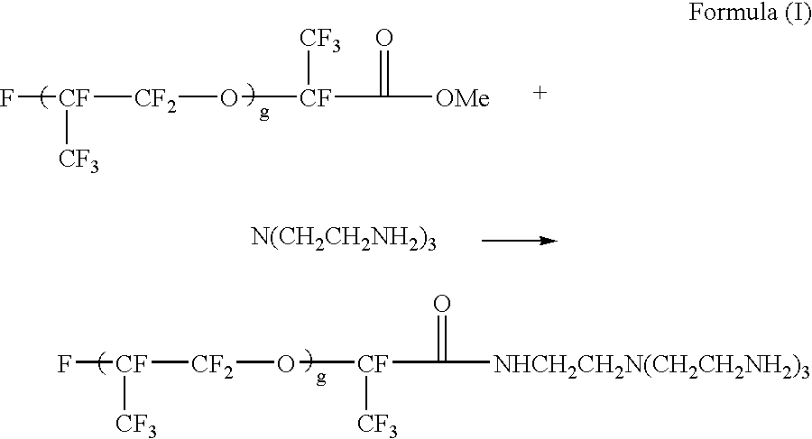
- 17.8 Gm of Krytox® methyl ester (DuPont, 17.8 g, MW=about ˜1780, g=about 10, DuPont) was dissolved in a solvent mixture containing 12 gm of 1,1,2-trichlorotrifluoroethane (Aldrich) and 1.5 gm of α,α,α-trifluorotoluene (Aldrich). The resultant solution was added drop by drop into a solution containing 7.3 gm of tris(2-aminoethyl)amine (Aldrich) in 25 gm of α,α,α-trifluorotoluene and 30 gm of 1,1,2-trichlorotrifluoroethane over 2 hours with stirring at room temperature. The mixture was then stirred for another 8 hours to allow the reaction to complete. The IR spectrum of the crude product clearly indicated the disappearance of C═O vibration for methyl ester at 1780 cm −1 and the appearance of C═O vibration for the amide product at 1695 cm−1. Solvents were removed by rotary evaporation followed by vacuum stripping at 100° C. for 4-6 hours. The crude product was then dissolved in 50 ml of PFS2 solvent (low m.w. perfluoropolyether from Ausimont) and extracted with 20 ml of ethyl acetate three times, then dried to yield 17 gm of purified product (Rf-amine1900) which showed excellent solubility in HT200. The product (Rf-amine1780) showed good solubility in HT200.
- Other reactive multifunctional R f-amines of Formula (I) having different molecular weights such as Rf-amine4900 (g=about 30), Rf-amine2000 (g=about 11), Rf-amine800 (g=about 4) and Rf-amine650 (g=about 3) were also synthesized according to the same procedure.
- 9.05 Gm of Desmodur® N3400 aliphatic polyisocyanate (from Bayer AG) and 0.49 gm of triethanolamine (99%, Dow) were dissolved in 3.79 gm of MEK. To the resultant solution, 13 gm of TiO 2 R706 (DuPont) was added and homogenized for 2 minutes with a rotor-stator homogenizer (IKA ULTRA-TURRAX T25, IKA WORKS) at ambient temperature. A solution containing 1.67 gm of 1,5-pentanediol (BASF), 1.35 gm of polypropylene oxide (m.w.=725, from Aldrich), 2.47 gm of MEK and 0.32 gm of a 2% dibutyltin dilaurate (Aldrich) solution in MEK was added and further homogenized for 2 minutes. In the final step, 0.9 gm of Rf-amine 4900 prepared from Preparation 1 in 40.0 gm of HT-200 (Ausimont) was added and homogenized for 2 minutes, followed by addition of additional 0.9 gm of Rf-amine 4900 in 33.0 gm of HT-200 and homogenization for 2 minutes. A low viscosity microcapsule dispersion was obtained.
- The microcapsule dispersion obtained was heated at 80° C. overnight and stirred under low shear to post-cure the particles. The resultant microcapsule dispersion was filtered through a 400-mesh (38 micrometer) screen. The particle and the solid content of the filtered dispersion was measured to be 29 wt % by weight with an IR-200 Moisture Analyzer (Denver Instrument Company). The average particle size of the filtered dispersion was measured with a Beckman Coulter LS230 Particle Analyzer to be about 2 μm.
- An EPD fluid containing 1.0 wt % by weight of CuPc-C 8F17 (structure given below) and various amount of the resultant TiO2-containing microcapsule dispersion in HT-200 was filled into the microcups which were then sealed and sandwiched between two ITO/PET films according to the procedure described in Preparation 3.

- A primer coating solution containing 33.2 gm of EB 600™ (UCB, Smyrna, Ga.), 16.12 gm of SR 399™ (Sartomer, Exton, Pa.), 16.12 gm of TMPTA (UCB, Smyrna, Ga.), 20.61 gm of HDODA (UCB, Smyrna, Ga.), 2 gm of Irgacure™ 369 (Ciba, Tarrytown, N.Y.), 0.1 gm of Irganox™ 1035 (Ciba), 44.35 gm of poly(ethyl methacrylate) (MW. 515,000, Aldrich, Milwaukee, Wis.) and 399.15 gm of MEK (methyl ethyl ketone) was mixed thoroughly and coated onto a 5 mil transparent conductor film (ITO/PET film, 5 mil OC50 from CPFilms, Martinsville, Va.) using a #4 drawdown bar. The coated ITO film was dried in an oven at 65° C. for 10 minutes and exposed to 1.8 J/cm 2 of UV light under nitrogen using a UV conveyer (DDU, Los Angles, Calif.).
TABLE 2 Preparation 3B Preparation of Microcups Microcup Composition Component Weight Part Source EB 600 33.15 UCB SR 399 32.24 Sartomer HDDA 20.61 UCB EB1360 6.00 UCB Hycar X43 8.00 B F Goodrich Irgacure 369 0.20 Ciba ITX 0.04 Aldrich Antioxidant Ir1035 0.10 Ciba - 33.15 Gm of EB 600™ (UCB, Smyrna, Ga.), 32.24 gm of SR 399™ (Sartomer, Exton, Pa.), 6 gm of EB1360™ (UCB, Smyrna, Ga.), 8 gm of Hycar 1300×43 (reactive liquid polymer, Noveon Inc. Cleveland, Ohio), 0.2 gm of lrgacure™ 369 (Ciba, Tarrytown, N.Y.), 0.04 gm of ITX (Isopropyl-9H-thioxanthen-9-one, Aldrich, Milwaukee, Wis.), 0.1 gm of irganox™ 1035 (Ciba, Tarrytown, N.Y.) and 20.61 gm of HDDA (1,6-hexanediol diacrylate, UCB, Smyrna, Ga.) were mixed thoroughly with a Stir-Pak mixer (Cole Parmer, Vernon, Ill.) at room temperature for about 1 hour and debubbled by a centrifuge at 2000 rpm for about 15 minutes.
- The microcup composition was slowly coated onto a 4″×4″ electroformed Ni male mold for an array of 100 μm (length)×100 μm (width)×25 μm (depth)×15 μm (width of top surface of the partition wall between cups) microcups. A plastic blade was used to remove excess of fluid and gently squeeze it into “valleys” of the Ni mold. The coated Ni mold was heated in an oven at 65° C. for 5 minutes and laminated with the primer coated ITO/PET film prepared in Preparation 3A, with the primer layer facing the Ni mold using a
GBC Eagle 35 laminator (GBC, Northbrook, Ill.) preset at a roller temperature of 100° C., lamination speed of 1 ft/min and the roll gap at “heavy gauge”. A UV curing station with a UV intensity of 2.5 mJ/cm2 was used to cure the panel for 5 seconds. The ITO/PET film was then peeled away from the Ni mold at a peeling angle of about 30 degree to give a 4″×4″ microcup array on ITO/PET. An acceptable release of the microcup array from the mold was observed. The thus obtained microcup array was further post-cured with a UV conveyor curing system (DDU, Los Angles, Calif.) with a UV dosage of 1.7 J/cm2. - An electrophoretic fluid containing 9.7% by weight (dry weight) of the TiO 2-containing microcapsules prepared according to the
Preparation 2, 1.0% by weight of CuPc-C8F17 and 0.5% by weight of Rf-amine2000 (based on the total dry weight of the TiO2-containing microcapsule) prepared according to Preparation 1 in HT-200 was filled into the 4″×4″ microcup array prepared from Preparation 3B using a #0 drawdown bar. The excess of fluid was scraped away by a rubber blade. - A sealing composition containing 14% by weight of polyurethane IROSTIC P9815-20 (from Huntsman Polyurethane) in MEK/IPAc/CHO (47.5/47.5/5) was overcoated onto the filled microcups using a Universal Blade Applicator and dried at room temperature to form a seamless sealing layer of about 2-3 μm dry thickness with good uniformity. The lamination of the electrode layer over the sealed microcups was accomplished by pressing the ITO side of an ITO/PET film (5 mil) onto the sealing layer by a laminator at 120° C. and at the speed of 20 cm/min.
- Single Layer Microcup EPD
- The resultant single layer microcup EPD prepared according to the Preparation 3C was then coated with a thin layer of black coating on the outer surface of the electrode on the sealing side of the display (the non-viewing side). The electrode film on the side opposite to the sealing layer is the viewing side from which all the electro-optic performances were measured. The test results including contrast ratio and Dmin at various normalized field strength are listed in Table 3.
- Staggered Two-Layer Microcup EPD
- An electrophoretic fluid containing 6.0% by weight (dry weight) of the TiO 2-containing microcapsules prepared according to
Preparation 2, 1.0 wt % by weight of CuPc-C8F17 and 0.5% by weight (based on the total dry weight of the TiO2-containing microparticles) of Rf-amine2000 (from Preparation 1) in HT200 was filled and sealed into a microcup array prepared in Preparation 3C (the lower layer). The sealed microcup layer was laminated to a second sealed microcup layer (the upper layer) prepared in the Comparative Example 15 to form a staggered two-layer EPD film in which the inactive partition areas of the upper microcup layer were arranged in a staggered manner with registration to the active microcup areas of the lower layer. The resultant two-layer EPD film was evaluated as in the Comparative Example 15. The contrast ratio and Dmin at various normalized field strength measured from the upper layer side are also summarized in Table 3. - Staggered Two-Layer Microcup EPD
- The same procedure of Example 16 was followed except that the upper microcup layer was filled with an electrophoretic fluid containing 9.7% by weight (dry weight) of TiO 2-containing microparticles from
Preparation 2, 1.0% by weight of CuPc-C8F17 and 0.5% by weight (based upon the total dry weight of the TiO2-containing microparticles) of Rf-amine2000 in HT200; and the lower microcup layer was filled with 9.7% by weight of the TiO2-containing microparticles, 1.5% by weight of CuPc-C8F17 and 0.5% by weight (based upon the total dry weight of the TiO2-containg microparticles) of Rf-amine 2000 in HT200. The contrast ratio and Dmin at various normalized field strength are summarized in Table 3. The contrast ratio and Dmin were shown to have been further improved by the increases in dye and particle concentrations in the lower layer. - Staggered Two-Layer Microcup EPD
- The same procedure of Example 16 was followed, except that the electrophoretic fluid of the upper microcup layer contained 9.7% by weight of the TiO 2-containing microparticles from
Preparation 2, 0.7% by weight of CuPc-C8F17 and 0.5% by weight (based upon the total dry weight of the TiO2-containg microparticles) of Rf-amine2000 in HT200; and the lower microcup layer contained 9.7% by weight of the TiO2-containing microparticles, 1.5% by weight of CuPc-C8F17 and 0.5% by weight (based upon the total dry weight of the TiO2-containg microparticles) of Rf-amine2000 in HT200. The contrast ratio and Dmin at various normalized field strength are summarized in Table 3.TABLE 3 Contrast Ratios and Dmin of Examples 15-18 Upper Layer Lower Layer wt % CuPc- wt % TiO2 wt % CuPc- wt % TiO2 Normalized Field Strength C8F17 microparticle C8F17 microparticle 10 20 30 40 Comparative 1.0 9.7 N.A. N.A. Contrast 2.50 9.00 9.20 9.50 Example 15 ratio Dmin 0.84 0.76 0.76 0.75 Example 16 1.0 9.7 1.0 6.0 Contrast 3.50 12.30 13.50 14.00 ratio Dmin 0.76 0.69 0.69 0.68 Example 17 1.0 9.7 1.5 9.7 Contrast 2.50 14.50 17.00 19.00 ratio Dmin 0.78 0.66 0.66 0.65 Example 18 2.0 9.7 1.5 9.7 Contrast 5.00 8.00 9.50 9.50 ratio Dmin 0.75 0.67 0.65 0.65 - It is evident from Table 3 that under the same normalized field strength, all of the two-layer EPDs (Examples 16-18) showed significantly higher contrast ratio and lower Dmin (higher reflectivity in the Dmin state) than the single layer EPD (Comparative Example 15).
- While the present invention has been described with reference to the specific embodiments thereof, it should be understood by those skilled in the art that various changes may be made and equivalents may be substituted without departing from the true spirit and scope of the invention. In addition, many modifications may be made to adapt a particular situation, materials, compositions, processes, process step or steps, to the objective, spirit and scope of the present invention. All such modifications are intended to be within the scope of the claims appended hereto. For example, it should be noted that the method of the invention for preparing microcups may also be used for preparing microcups for liquid crystal displays. Similarly, the microcup selective filling, sealing and ITO laminating methods of the invention may also be employed in the manufacture of liquid crystal displays. Moreover, both the one-pass and two-pass sealing and filling processes and compositions are also useful to fill and seal electrophoretic displays having the groove type, the grid type as shown in FIGS. 6 a, 6 b and 6 c and other partition type of cell structures.
- It is therefore wished that this invention to be defined by the scope of the appended claims as broadly as the prior art will permit, and in view of the specification if need be.
Claims (54)
Priority Applications (4)
| Application Number | Priority Date | Filing Date | Title |
|---|---|---|---|
| US10/310,681 US7205355B2 (en) | 2001-06-04 | 2002-12-04 | Composition and process for the manufacture of an improved electrophoretic display |
| TW092131970A TWI255955B (en) | 2002-12-04 | 2003-11-14 | Composition and process for the manufacture of an improved electrophoretic display |
| PCT/US2003/036879 WO2004051354A1 (en) | 2002-12-04 | 2003-11-18 | Multilayer display and manufacturing method using sealant composition |
| AU2003291070A AU2003291070A1 (en) | 2002-12-04 | 2003-11-18 | Multilayer display and manufacturing method using sealant composition |
Applications Claiming Priority (2)
| Application Number | Priority Date | Filing Date | Title |
|---|---|---|---|
| US09/874,391 US20020188053A1 (en) | 2001-06-04 | 2001-06-04 | Composition and process for the sealing of microcups in roll-to-roll display manufacturing |
| US10/310,681 US7205355B2 (en) | 2001-06-04 | 2002-12-04 | Composition and process for the manufacture of an improved electrophoretic display |
Related Parent Applications (1)
| Application Number | Title | Priority Date | Filing Date |
|---|---|---|---|
| US09/874,391 Continuation-In-Part US20020188053A1 (en) | 2001-06-04 | 2001-06-04 | Composition and process for the sealing of microcups in roll-to-roll display manufacturing |
Publications (2)
| Publication Number | Publication Date |
|---|---|
| US20030176557A1 true US20030176557A1 (en) | 2003-09-18 |
| US7205355B2 US7205355B2 (en) | 2007-04-17 |
Family
ID=32468088
Family Applications (1)
| Application Number | Title | Priority Date | Filing Date |
|---|---|---|---|
| US10/310,681 Expired - Lifetime US7205355B2 (en) | 2001-06-04 | 2002-12-04 | Composition and process for the manufacture of an improved electrophoretic display |
Country Status (4)
| Country | Link |
|---|---|
| US (1) | US7205355B2 (en) |
| AU (1) | AU2003291070A1 (en) |
| TW (1) | TWI255955B (en) |
| WO (1) | WO2004051354A1 (en) |
Cited By (8)
| Publication number | Priority date | Publication date | Assignee | Title |
|---|---|---|---|---|
| WO2004051354A1 (en) * | 2002-12-04 | 2004-06-17 | Sipix Imaging, Inc. | Multilayer display and manufacturing method using sealant composition |
| US20040141596A1 (en) * | 2003-01-16 | 2004-07-22 | Sbc Properties, L.P. | Voice extensible markup language enhancements of intelligent network services |
| US20070243332A1 (en) * | 2001-06-04 | 2007-10-18 | Zang Hongmei | Composition and process for the sealing of microcups in roll-to-roll display manufacturing |
| US20100090943A1 (en) * | 2008-10-14 | 2010-04-15 | Fricke Peter J | Electrophoretic Display Apparatus and Method |
| US20110102313A1 (en) * | 2009-10-29 | 2011-05-05 | Au Optronics Corporation | Electrophoresis display panel |
| US8652565B2 (en) | 2009-07-29 | 2014-02-18 | Seiko Epson Corporation | Sealing method of sealing dispersion liquid containing and electrophoretic particles, and electrophoretic display |
| US20150187282A1 (en) * | 2013-12-27 | 2015-07-02 | E Ink Holdings Inc. | Display module |
| CN112470066A (en) * | 2018-08-10 | 2021-03-09 | 伊英克加利福尼亚有限责任公司 | Drive waveform for switchable light collimating layer comprising a bistable electrophoretic fluid |
Families Citing this family (34)
| Publication number | Priority date | Publication date | Assignee | Title |
|---|---|---|---|---|
| US7715088B2 (en) * | 2000-03-03 | 2010-05-11 | Sipix Imaging, Inc. | Electrophoretic display |
| JP2004514165A (en) | 2000-11-17 | 2004-05-13 | ディープ ヴィデオ イメージング リミテッド | How to change a display screen mat from an optically smooth surface |
| NZ511255A (en) | 2001-04-20 | 2003-12-19 | Deep Video Imaging Ltd | Multi-focal plane display having an optical retarder and a diffuser interposed between its screens |
| NZ514500A (en) | 2001-10-11 | 2004-06-25 | Deep Video Imaging Ltd | A multiplane visual display unit with a transparent emissive layer disposed between two display planes |
| JP2005522715A (en) | 2002-03-17 | 2005-07-28 | ディープ ヴィデオ イメージング リミテッド | How to control the point spread function of an image |
| US9137525B2 (en) * | 2002-07-15 | 2015-09-15 | Pure Depth Limited | Multilayer video screen |
| NZ521505A (en) | 2002-09-20 | 2005-05-27 | Deep Video Imaging Ltd | Multi-view display |
| FR2872590B1 (en) | 2004-07-02 | 2006-10-27 | Essilor Int | METHOD FOR PRODUCING AN OPHTHALMIC GLASS AND OPTICAL COMPONENT SUITABLE FOR CARRYING OUT SAID METHOD |
| JP2006293150A (en) * | 2005-04-13 | 2006-10-26 | Bridgestone Corp | Panel for information display |
| FR2888947B1 (en) | 2005-07-20 | 2007-10-12 | Essilor Int | OPTICAL CELL COMPONENT |
| FR2888951B1 (en) | 2005-07-20 | 2008-02-08 | Essilor Int | RANDOMIZED PIXELLIZED OPTICAL COMPONENT, METHOD FOR MANUFACTURING THE SAME, AND USE THEREOF IN THE MANUFACTURE OF A TRANSPARENT OPTICAL ELEMENT |
| FR2888950B1 (en) | 2005-07-20 | 2007-10-12 | Essilor Int | TRANSPARENT PIXELLIZED OPTICAL COMPONENT WITH ABSORBENT WALLS ITS MANUFACTURING METHOD AND USE IN FARICATION OF A TRANSPARENT OPTICAL ELEMENT |
| FR2888948B1 (en) | 2005-07-20 | 2007-10-12 | Essilor Int | PIXELLIZED TRANSPARENT OPTIC COMPONENT COMPRISING AN ABSORBENT COATING, METHOD FOR PRODUCING THE SAME AND USE THEREOF IN AN OPTICAL ELEMENT |
| FR2907559B1 (en) | 2006-10-19 | 2009-02-13 | Essilor Int | ELECRO-COMMANDABLE OPTICAL COMPONENT COMPRISING A SET OF CELLS |
| FR2910642B1 (en) * | 2006-12-26 | 2009-03-06 | Essilor Int | TRANSPARENT OPTICAL COMPONENT WITH TWO CELL ARRAYS |
| FR2911404B1 (en) | 2007-01-17 | 2009-04-10 | Essilor Int | TRANSPARENT OPTICAL COMPONENT WITH CELLS FILLED WITH OPTICAL MATERIAL |
| CN101897196A (en) * | 2007-08-22 | 2010-11-24 | 普尔·代普斯有限公司 | Determine the position of the space diffuser of multicompartment display |
| US7894123B2 (en) | 2009-02-27 | 2011-02-22 | Raytheon Company | Multilayer light modulator |
| WO2010136925A1 (en) * | 2009-05-29 | 2010-12-02 | Koninklijke Philips Electronics N.V. | Electrophoretic device |
| JP5516173B2 (en) * | 2009-10-14 | 2014-06-11 | セイコーエプソン株式会社 | Display sheet, display device and electronic device |
| CN107450248A (en) * | 2012-02-14 | 2017-12-08 | 伊英克加利福尼亚有限责任公司 | Micro-cup for electrophoretic display device (EPD) designs |
| KR101952445B1 (en) * | 2012-05-10 | 2019-04-26 | 리쿠아비스타 비.브이. | Eloctro wetting display apparatus |
| US10401668B2 (en) * | 2012-05-30 | 2019-09-03 | E Ink California, Llc | Display device with visually-distinguishable watermark area and non-watermark area |
| US9671609B2 (en) | 2014-08-01 | 2017-06-06 | Sct Technology, Ltd. | Display device and method for reducing moiré effects using the same |
| PL3402851T3 (en) | 2016-01-17 | 2021-12-20 | E Ink California, Llc | Branched polyol additives for electrophoretic media |
| EP3403141A4 (en) * | 2016-01-17 | 2019-01-16 | E Ink California, LLC | Polyhydroxy compositions for sealing electrophoretic displays |
| US10061123B2 (en) | 2016-01-17 | 2018-08-28 | E Ink California, Llc | Surfactants for improving electrophoretic media performance |
| US10545622B2 (en) * | 2016-05-20 | 2020-01-28 | E Ink Corporation | Magnetically-responsive display including a recording layer configured for local and global write/erase |
| US10802373B1 (en) | 2017-06-26 | 2020-10-13 | E Ink Corporation | Reflective microcells for electrophoretic displays and methods of making the same |
| US10921676B2 (en) | 2017-08-30 | 2021-02-16 | E Ink Corporation | Electrophoretic medium |
| US10698265B1 (en) | 2017-10-06 | 2020-06-30 | E Ink California, Llc | Quantum dot film |
| US11397366B2 (en) | 2018-08-10 | 2022-07-26 | E Ink California, Llc | Switchable light-collimating layer including bistable electrophoretic fluid |
| JP7108779B2 (en) | 2018-08-10 | 2022-07-28 | イー インク カリフォルニア, エルエルシー | Switchable light collimating layer with reflector |
| EP3927265A1 (en) | 2019-02-22 | 2021-12-29 | Smith&Nephew, Inc. | Combination electrosurgical and mechanical resection device |
Citations (39)
| Publication number | Priority date | Publication date | Assignee | Title |
|---|---|---|---|---|
| US879408A (en) * | 1907-09-09 | 1908-02-18 | Christopher W Owens | Duplex gravity gate-latch. |
| US3612758A (en) * | 1969-10-03 | 1971-10-12 | Xerox Corp | Color display device |
| US3668106A (en) * | 1970-04-09 | 1972-06-06 | Matsushita Electric Ind Co Ltd | Electrophoretic display device |
| US4071430A (en) * | 1976-12-06 | 1978-01-31 | North American Philips Corporation | Electrophoretic image display having an improved switching time |
| US4093534A (en) * | 1974-02-12 | 1978-06-06 | Plessey Handel Und Investments Ag | Working fluids for electrophoretic image display devices |
| US4285801A (en) * | 1979-09-20 | 1981-08-25 | Xerox Corporation | Electrophoretic display composition |
| US4411115A (en) * | 1978-04-05 | 1983-10-25 | Usm Corporation | Spacer frames for multi-pane glazing units |
| US4680103A (en) * | 1986-01-24 | 1987-07-14 | Epid. Inc. | Positive particles in electrophoretic display device composition |
| US4741988A (en) * | 1985-05-08 | 1988-05-03 | U.S. Philips Corp. | Patterned polyimide film, a photosensitive polyamide acid derivative and an electrophoretic image-display cell |
| US5234987A (en) * | 1992-07-06 | 1993-08-10 | Adco Products, Inc. | Solvent-based adhesive composition for roofing membranes |
| US5276438A (en) * | 1991-08-29 | 1994-01-04 | Copytele, Inc. | Electrophoretic display panel with internal mesh background screen |
| US5279511A (en) * | 1992-10-21 | 1994-01-18 | Copytele, Inc. | Method of filling an electrophoretic display |
| US5380362A (en) * | 1993-07-16 | 1995-01-10 | Copytele, Inc. | Suspension for use in electrophoretic image display systems |
| US5403518A (en) * | 1993-12-02 | 1995-04-04 | Copytele, Inc. | Formulations for improved electrophoretic display suspensions and related methods |
| US5573711A (en) * | 1994-05-26 | 1996-11-12 | Copytele, Inc. | Planar fluorinated dielectric suspensions for electrophoretic image displays and related methods |
| US5589100A (en) * | 1990-06-08 | 1996-12-31 | Hercules Incorporated | Dichroic azo dyes |
| US5699097A (en) * | 1994-04-22 | 1997-12-16 | Kabushiki Kaisha Toshiba | Display medium and method for display therewith |
| US5914806A (en) * | 1998-02-11 | 1999-06-22 | International Business Machines Corporation | Stable electrophoretic particles for displays |
| US5930026A (en) * | 1996-10-25 | 1999-07-27 | Massachusetts Institute Of Technology | Nonemissive displays and piezoelectric power supplies therefor |
| US5932648A (en) * | 1995-09-15 | 1999-08-03 | Shell Oil Company | Low VOC, high solids fumigation adhesive composition |
| US5961804A (en) * | 1997-03-18 | 1999-10-05 | Massachusetts Institute Of Technology | Microencapsulated electrophoretic display |
| US5993900A (en) * | 1996-06-24 | 1999-11-30 | Shell Oil Company | Acid-grafted hydrogenated elastomer/endblock aromatic resin primer |
| US6017584A (en) * | 1995-07-20 | 2000-01-25 | E Ink Corporation | Multi-color electrophoretic displays and materials for making the same |
| US6067185A (en) * | 1997-08-28 | 2000-05-23 | E Ink Corporation | Process for creating an encapsulated electrophoretic display |
| US6113810A (en) * | 1993-05-21 | 2000-09-05 | Copytele, Inc. | Methods of preparing electrophoretic dispersions containing two types of particles with different colors and opposite charges |
| US6120588A (en) * | 1996-07-19 | 2000-09-19 | E Ink Corporation | Electronically addressable microencapsulated ink and display thereof |
| US6120839A (en) * | 1995-07-20 | 2000-09-19 | E Ink Corporation | Electro-osmotic displays and materials for making the same |
| US6172798B1 (en) * | 1998-04-27 | 2001-01-09 | E Ink Corporation | Shutter mode microencapsulated electrophoretic display |
| US6184856B1 (en) * | 1998-09-16 | 2001-02-06 | International Business Machines Corporation | Transmissive electrophoretic display with laterally adjacent color cells |
| US6312304B1 (en) * | 1998-12-15 | 2001-11-06 | E Ink Corporation | Assembly of microencapsulated electronic displays |
| US6327072B1 (en) * | 1999-04-06 | 2001-12-04 | E Ink Corporation | Microcell electrophoretic displays |
| US6337761B1 (en) * | 1999-10-01 | 2002-01-08 | Lucent Technologies Inc. | Electrophoretic display and method of making the same |
| US20020018043A1 (en) * | 2000-06-14 | 2002-02-14 | Masahiro Nakanishi | Electrophoretic display device and process for production thereof |
| US6392786B1 (en) * | 1999-07-01 | 2002-05-21 | E Ink Corporation | Electrophoretic medium provided with spacers |
| US6400492B1 (en) * | 1999-06-11 | 2002-06-04 | Ricoh Company Limited | Electrophoretic display liquid, and electrophoretic display medium, method and device using the liquid |
| US6751007B2 (en) * | 2001-08-20 | 2004-06-15 | Sipix Imaging, Inc. | Transflective electrophoretic display |
| US6788449B2 (en) * | 2000-03-03 | 2004-09-07 | Sipix Imaging, Inc. | Electrophoretic display and novel process for its manufacture |
| US6795229B2 (en) * | 2001-08-28 | 2004-09-21 | Sipix Imaging, Inc. | Electrophoretic display with sub relief structure for high contrast ratio and improved shear and/or compression resistance |
| US6850355B2 (en) * | 2001-07-27 | 2005-02-01 | Sipix Imaging, Inc. | Electrophoretic display with color filters |
Family Cites Families (7)
| Publication number | Priority date | Publication date | Assignee | Title |
|---|---|---|---|---|
| JPS59171930A (en) | 1983-03-18 | 1984-09-28 | Matsushita Electric Ind Co Ltd | Electrophoresis display element |
| US5124405A (en) | 1990-07-27 | 1992-06-23 | Shell Oil Company | Method of chemically crosslinking unsaturated polymers |
| US6930818B1 (en) | 2000-03-03 | 2005-08-16 | Sipix Imaging, Inc. | Electrophoretic display and novel process for its manufacture |
| US6933098B2 (en) | 2000-01-11 | 2005-08-23 | Sipix Imaging Inc. | Process for roll-to-roll manufacture of a display by synchronized photolithographic exposure on a substrate web |
| US6545797B2 (en) | 2001-06-11 | 2003-04-08 | Sipix Imaging, Inc. | Process for imagewise opening and filling color display components and color displays manufactured thereof |
| US6795138B2 (en) | 2001-01-11 | 2004-09-21 | Sipix Imaging, Inc. | Transmissive or reflective liquid crystal display and novel process for its manufacture |
| US7205355B2 (en) | 2001-06-04 | 2007-04-17 | Sipix Imaging, Inc. | Composition and process for the manufacture of an improved electrophoretic display |
-
2002
- 2002-12-04 US US10/310,681 patent/US7205355B2/en not_active Expired - Lifetime
-
2003
- 2003-11-14 TW TW092131970A patent/TWI255955B/en not_active IP Right Cessation
- 2003-11-18 AU AU2003291070A patent/AU2003291070A1/en not_active Abandoned
- 2003-11-18 WO PCT/US2003/036879 patent/WO2004051354A1/en not_active Application Discontinuation
Patent Citations (40)
| Publication number | Priority date | Publication date | Assignee | Title |
|---|---|---|---|---|
| US879408A (en) * | 1907-09-09 | 1908-02-18 | Christopher W Owens | Duplex gravity gate-latch. |
| US3612758A (en) * | 1969-10-03 | 1971-10-12 | Xerox Corp | Color display device |
| US3668106A (en) * | 1970-04-09 | 1972-06-06 | Matsushita Electric Ind Co Ltd | Electrophoretic display device |
| US4093534A (en) * | 1974-02-12 | 1978-06-06 | Plessey Handel Und Investments Ag | Working fluids for electrophoretic image display devices |
| US4071430A (en) * | 1976-12-06 | 1978-01-31 | North American Philips Corporation | Electrophoretic image display having an improved switching time |
| US4411115A (en) * | 1978-04-05 | 1983-10-25 | Usm Corporation | Spacer frames for multi-pane glazing units |
| US4285801A (en) * | 1979-09-20 | 1981-08-25 | Xerox Corporation | Electrophoretic display composition |
| US4741988A (en) * | 1985-05-08 | 1988-05-03 | U.S. Philips Corp. | Patterned polyimide film, a photosensitive polyamide acid derivative and an electrophoretic image-display cell |
| US4680103A (en) * | 1986-01-24 | 1987-07-14 | Epid. Inc. | Positive particles in electrophoretic display device composition |
| US5589100A (en) * | 1990-06-08 | 1996-12-31 | Hercules Incorporated | Dichroic azo dyes |
| US5276438A (en) * | 1991-08-29 | 1994-01-04 | Copytele, Inc. | Electrophoretic display panel with internal mesh background screen |
| US5234987A (en) * | 1992-07-06 | 1993-08-10 | Adco Products, Inc. | Solvent-based adhesive composition for roofing membranes |
| US5279511A (en) * | 1992-10-21 | 1994-01-18 | Copytele, Inc. | Method of filling an electrophoretic display |
| US6113810A (en) * | 1993-05-21 | 2000-09-05 | Copytele, Inc. | Methods of preparing electrophoretic dispersions containing two types of particles with different colors and opposite charges |
| US5380362A (en) * | 1993-07-16 | 1995-01-10 | Copytele, Inc. | Suspension for use in electrophoretic image display systems |
| US5403518A (en) * | 1993-12-02 | 1995-04-04 | Copytele, Inc. | Formulations for improved electrophoretic display suspensions and related methods |
| US5699097A (en) * | 1994-04-22 | 1997-12-16 | Kabushiki Kaisha Toshiba | Display medium and method for display therewith |
| US5573711A (en) * | 1994-05-26 | 1996-11-12 | Copytele, Inc. | Planar fluorinated dielectric suspensions for electrophoretic image displays and related methods |
| US6120839A (en) * | 1995-07-20 | 2000-09-19 | E Ink Corporation | Electro-osmotic displays and materials for making the same |
| US6017584A (en) * | 1995-07-20 | 2000-01-25 | E Ink Corporation | Multi-color electrophoretic displays and materials for making the same |
| US5932648A (en) * | 1995-09-15 | 1999-08-03 | Shell Oil Company | Low VOC, high solids fumigation adhesive composition |
| US5993900A (en) * | 1996-06-24 | 1999-11-30 | Shell Oil Company | Acid-grafted hydrogenated elastomer/endblock aromatic resin primer |
| US6120588A (en) * | 1996-07-19 | 2000-09-19 | E Ink Corporation | Electronically addressable microencapsulated ink and display thereof |
| US5930026A (en) * | 1996-10-25 | 1999-07-27 | Massachusetts Institute Of Technology | Nonemissive displays and piezoelectric power supplies therefor |
| US5961804A (en) * | 1997-03-18 | 1999-10-05 | Massachusetts Institute Of Technology | Microencapsulated electrophoretic display |
| US6067185A (en) * | 1997-08-28 | 2000-05-23 | E Ink Corporation | Process for creating an encapsulated electrophoretic display |
| US5914806A (en) * | 1998-02-11 | 1999-06-22 | International Business Machines Corporation | Stable electrophoretic particles for displays |
| US6172798B1 (en) * | 1998-04-27 | 2001-01-09 | E Ink Corporation | Shutter mode microencapsulated electrophoretic display |
| US6184856B1 (en) * | 1998-09-16 | 2001-02-06 | International Business Machines Corporation | Transmissive electrophoretic display with laterally adjacent color cells |
| US6312304B1 (en) * | 1998-12-15 | 2001-11-06 | E Ink Corporation | Assembly of microencapsulated electronic displays |
| US6327072B1 (en) * | 1999-04-06 | 2001-12-04 | E Ink Corporation | Microcell electrophoretic displays |
| US6400492B1 (en) * | 1999-06-11 | 2002-06-04 | Ricoh Company Limited | Electrophoretic display liquid, and electrophoretic display medium, method and device using the liquid |
| US6392786B1 (en) * | 1999-07-01 | 2002-05-21 | E Ink Corporation | Electrophoretic medium provided with spacers |
| US6337761B1 (en) * | 1999-10-01 | 2002-01-08 | Lucent Technologies Inc. | Electrophoretic display and method of making the same |
| US6788449B2 (en) * | 2000-03-03 | 2004-09-07 | Sipix Imaging, Inc. | Electrophoretic display and novel process for its manufacture |
| US20020018043A1 (en) * | 2000-06-14 | 2002-02-14 | Masahiro Nakanishi | Electrophoretic display device and process for production thereof |
| US6750844B2 (en) * | 2000-06-14 | 2004-06-15 | Canon Kabushiki Kaisha | Electrophoretic display device and process for production thereof |
| US6850355B2 (en) * | 2001-07-27 | 2005-02-01 | Sipix Imaging, Inc. | Electrophoretic display with color filters |
| US6751007B2 (en) * | 2001-08-20 | 2004-06-15 | Sipix Imaging, Inc. | Transflective electrophoretic display |
| US6795229B2 (en) * | 2001-08-28 | 2004-09-21 | Sipix Imaging, Inc. | Electrophoretic display with sub relief structure for high contrast ratio and improved shear and/or compression resistance |
Cited By (12)
| Publication number | Priority date | Publication date | Assignee | Title |
|---|---|---|---|---|
| US7205355B2 (en) | 2001-06-04 | 2007-04-17 | Sipix Imaging, Inc. | Composition and process for the manufacture of an improved electrophoretic display |
| US20070243332A1 (en) * | 2001-06-04 | 2007-10-18 | Zang Hongmei | Composition and process for the sealing of microcups in roll-to-roll display manufacturing |
| US8361356B2 (en) | 2001-06-04 | 2013-01-29 | Sipix Imaging, Inc. | Composition and process for the sealing of microcups in roll-to-roll display manufacturing |
| WO2004051354A1 (en) * | 2002-12-04 | 2004-06-17 | Sipix Imaging, Inc. | Multilayer display and manufacturing method using sealant composition |
| US20040141596A1 (en) * | 2003-01-16 | 2004-07-22 | Sbc Properties, L.P. | Voice extensible markup language enhancements of intelligent network services |
| US7336771B2 (en) | 2003-01-16 | 2008-02-26 | At&T Knowledge Ventures, L.P. | Voice extensible markup language enhancements of intelligent network services |
| US20100090943A1 (en) * | 2008-10-14 | 2010-04-15 | Fricke Peter J | Electrophoretic Display Apparatus and Method |
| US8652565B2 (en) | 2009-07-29 | 2014-02-18 | Seiko Epson Corporation | Sealing method of sealing dispersion liquid containing and electrophoretic particles, and electrophoretic display |
| US20110102313A1 (en) * | 2009-10-29 | 2011-05-05 | Au Optronics Corporation | Electrophoresis display panel |
| US20150187282A1 (en) * | 2013-12-27 | 2015-07-02 | E Ink Holdings Inc. | Display module |
| US9373290B2 (en) * | 2013-12-27 | 2016-06-21 | E Ink Holdings Inc. | Display module with E-paper display component and auxiliary display component |
| CN112470066A (en) * | 2018-08-10 | 2021-03-09 | 伊英克加利福尼亚有限责任公司 | Drive waveform for switchable light collimating layer comprising a bistable electrophoretic fluid |
Also Published As
| Publication number | Publication date |
|---|---|
| TWI255955B (en) | 2006-06-01 |
| AU2003291070A1 (en) | 2004-06-23 |
| TW200424250A (en) | 2004-11-16 |
| WO2004051354A1 (en) | 2004-06-17 |
| US7205355B2 (en) | 2007-04-17 |
Similar Documents
| Publication | Publication Date | Title |
|---|---|---|
| US7205355B2 (en) | Composition and process for the manufacture of an improved electrophoretic display | |
| US7072095B2 (en) | Electrophoretic display and novel process for its manufacture | |
| KR100859305B1 (en) | Composition and process for the sealing of microcups in roll-to-roll display manufacturing | |
| US6788452B2 (en) | Process for manufacture of improved color displays | |
| US6987605B2 (en) | Transflective electrophoretic display | |
| US6795229B2 (en) | Electrophoretic display with sub relief structure for high contrast ratio and improved shear and/or compression resistance | |
| US6947202B2 (en) | Electrophoretic display with sub relief structure for high contrast ratio and improved shear and/or compression resistance | |
| US9081250B2 (en) | Electrophoretic display and process for its manufacture | |
| US6885495B2 (en) | Electrophoretic display with in-plane switching | |
| US6873452B2 (en) | Compositions and processes for format flexible, roll-to-roll manufacturing of electrophoretic displays | |
| US8361356B2 (en) | Composition and process for the sealing of microcups in roll-to-roll display manufacturing | |
| US20030179437A1 (en) | Electrophoretic display and novel process for its manufacture | |
| US20020075556A1 (en) | Electrophoretic display and novel process for its manufacture | |
| JP2005509690A5 (en) | ||
| CN108351570A (en) | The method for sealing micro unit container with phenyl ethylamine mixture | |
| EP1407321A1 (en) | In-plane switching electrophoretic display |
Legal Events
| Date | Code | Title | Description |
|---|---|---|---|
| AS | Assignment |
Owner name: SIPIX IMAGING INC., CALIFORNIA Free format text: ASSIGNMENT OF ASSIGNORS INTEREST;ASSIGNORS:LIANG, RONG-CHANG;ZANG, HONGMEI;WANG, XIAOJIA;REEL/FRAME:014091/0747;SIGNING DATES FROM 20030326 TO 20030327 |
|
| STCF | Information on status: patent grant |
Free format text: PATENTED CASE |
|
| FEPP | Fee payment procedure |
Free format text: PAT HOLDER NO LONGER CLAIMS SMALL ENTITY STATUS, ENTITY STATUS SET TO UNDISCOUNTED (ORIGINAL EVENT CODE: STOL); ENTITY STATUS OF PATENT OWNER: LARGE ENTITY |
|
| FPAY | Fee payment |
Year of fee payment: 4 |
|
| AS | Assignment |
Owner name: E INK CALIFORNIA, LLC, CALIFORNIA Free format text: CHANGE OF NAME;ASSIGNOR:SIPIX IMAGING, INC.;REEL/FRAME:033280/0408 Effective date: 20140701 |
|
| FPAY | Fee payment |
Year of fee payment: 8 |
|
| MAFP | Maintenance fee payment |
Free format text: PAYMENT OF MAINTENANCE FEE, 12TH YEAR, LARGE ENTITY (ORIGINAL EVENT CODE: M1553); ENTITY STATUS OF PATENT OWNER: LARGE ENTITY Year of fee payment: 12 |