US20030002450A1 - Method and apparatus for transmitting data in a time division duplexed (TDD) communication system - Google Patents
Method and apparatus for transmitting data in a time division duplexed (TDD) communication system Download PDFInfo
- Publication number
- US20030002450A1 US20030002450A1 US09/887,225 US88722501A US2003002450A1 US 20030002450 A1 US20030002450 A1 US 20030002450A1 US 88722501 A US88722501 A US 88722501A US 2003002450 A1 US2003002450 A1 US 2003002450A1
- Authority
- US
- United States
- Prior art keywords
- data
- transmission
- communication link
- receiver unit
- modulation symbols
- Prior art date
- Legal status (The legal status is an assumption and is not a legal conclusion. Google has not performed a legal analysis and makes no representation as to the accuracy of the status listed.)
- Granted
Links
Images


Classifications
-
- H—ELECTRICITY
- H04—ELECTRIC COMMUNICATION TECHNIQUE
- H04L—TRANSMISSION OF DIGITAL INFORMATION, e.g. TELEGRAPHIC COMMUNICATION
- H04L1/00—Arrangements for detecting or preventing errors in the information received
- H04L1/0001—Systems modifying transmission characteristics according to link quality, e.g. power backoff
- H04L1/0023—Systems modifying transmission characteristics according to link quality, e.g. power backoff characterised by the signalling
- H04L1/0032—Without explicit signalling
-
- H—ELECTRICITY
- H04—ELECTRIC COMMUNICATION TECHNIQUE
- H04L—TRANSMISSION OF DIGITAL INFORMATION, e.g. TELEGRAPHIC COMMUNICATION
- H04L27/00—Modulated-carrier systems
- H04L27/26—Systems using multi-frequency codes
-
- H—ELECTRICITY
- H04—ELECTRIC COMMUNICATION TECHNIQUE
- H04B—TRANSMISSION
- H04B7/00—Radio transmission systems, i.e. using radiation field
- H04B7/02—Diversity systems; Multi-antenna system, i.e. transmission or reception using multiple antennas
- H04B7/04—Diversity systems; Multi-antenna system, i.e. transmission or reception using multiple antennas using two or more spaced independent antennas
- H04B7/0413—MIMO systems
- H04B7/0426—Power distribution
- H04B7/0434—Power distribution using multiple eigenmodes
-
- H—ELECTRICITY
- H04—ELECTRIC COMMUNICATION TECHNIQUE
- H04B—TRANSMISSION
- H04B7/00—Radio transmission systems, i.e. using radiation field
- H04B7/02—Diversity systems; Multi-antenna system, i.e. transmission or reception using multiple antennas
- H04B7/04—Diversity systems; Multi-antenna system, i.e. transmission or reception using multiple antennas using two or more spaced independent antennas
- H04B7/06—Diversity systems; Multi-antenna system, i.e. transmission or reception using multiple antennas using two or more spaced independent antennas at the transmitting station
- H04B7/0613—Diversity systems; Multi-antenna system, i.e. transmission or reception using multiple antennas using two or more spaced independent antennas at the transmitting station using simultaneous transmission
- H04B7/0615—Diversity systems; Multi-antenna system, i.e. transmission or reception using multiple antennas using two or more spaced independent antennas at the transmitting station using simultaneous transmission of weighted versions of same signal
- H04B7/0619—Diversity systems; Multi-antenna system, i.e. transmission or reception using multiple antennas using two or more spaced independent antennas at the transmitting station using simultaneous transmission of weighted versions of same signal using feedback from receiving side
- H04B7/0621—Feedback content
- H04B7/0626—Channel coefficients, e.g. channel state information [CSI]
-
- H—ELECTRICITY
- H04—ELECTRIC COMMUNICATION TECHNIQUE
- H04L—TRANSMISSION OF DIGITAL INFORMATION, e.g. TELEGRAPHIC COMMUNICATION
- H04L1/00—Arrangements for detecting or preventing errors in the information received
- H04L1/0001—Systems modifying transmission characteristics according to link quality, e.g. power backoff
- H04L1/0009—Systems modifying transmission characteristics according to link quality, e.g. power backoff by adapting the channel coding
- H04L1/0013—Rate matching, e.g. puncturing or repetition of code symbols
-
- H—ELECTRICITY
- H04—ELECTRIC COMMUNICATION TECHNIQUE
- H04L—TRANSMISSION OF DIGITAL INFORMATION, e.g. TELEGRAPHIC COMMUNICATION
- H04L1/00—Arrangements for detecting or preventing errors in the information received
- H04L1/0001—Systems modifying transmission characteristics according to link quality, e.g. power backoff
- H04L1/0023—Systems modifying transmission characteristics according to link quality, e.g. power backoff characterised by the signalling
- H04L1/0026—Transmission of channel quality indication
-
- H—ELECTRICITY
- H04—ELECTRIC COMMUNICATION TECHNIQUE
- H04L—TRANSMISSION OF DIGITAL INFORMATION, e.g. TELEGRAPHIC COMMUNICATION
- H04L1/00—Arrangements for detecting or preventing errors in the information received
- H04L1/0001—Systems modifying transmission characteristics according to link quality, e.g. power backoff
- H04L1/0033—Systems modifying transmission characteristics according to link quality, e.g. power backoff arrangements specific to the transmitter
- H04L1/0034—Systems modifying transmission characteristics according to link quality, e.g. power backoff arrangements specific to the transmitter where the transmitter decides based on inferences, e.g. use of implicit signalling
-
- H—ELECTRICITY
- H04—ELECTRIC COMMUNICATION TECHNIQUE
- H04L—TRANSMISSION OF DIGITAL INFORMATION, e.g. TELEGRAPHIC COMMUNICATION
- H04L1/00—Arrangements for detecting or preventing errors in the information received
- H04L1/02—Arrangements for detecting or preventing errors in the information received by diversity reception
- H04L1/06—Arrangements for detecting or preventing errors in the information received by diversity reception using space diversity
-
- H—ELECTRICITY
- H04—ELECTRIC COMMUNICATION TECHNIQUE
- H04L—TRANSMISSION OF DIGITAL INFORMATION, e.g. TELEGRAPHIC COMMUNICATION
- H04L25/00—Baseband systems
- H04L25/02—Details ; arrangements for supplying electrical power along data transmission lines
- H04L25/0202—Channel estimation
- H04L25/0224—Channel estimation using sounding signals
- H04L25/0226—Channel estimation using sounding signals sounding signals per se
-
- H—ELECTRICITY
- H04—ELECTRIC COMMUNICATION TECHNIQUE
- H04L—TRANSMISSION OF DIGITAL INFORMATION, e.g. TELEGRAPHIC COMMUNICATION
- H04L25/00—Baseband systems
- H04L25/02—Details ; arrangements for supplying electrical power along data transmission lines
- H04L25/03—Shaping networks in transmitter or receiver, e.g. adaptive shaping networks
- H04L25/03006—Arrangements for removing intersymbol interference
- H04L25/03343—Arrangements at the transmitter end
-
- H—ELECTRICITY
- H04—ELECTRIC COMMUNICATION TECHNIQUE
- H04L—TRANSMISSION OF DIGITAL INFORMATION, e.g. TELEGRAPHIC COMMUNICATION
- H04L5/00—Arrangements affording multiple use of the transmission path
- H04L5/0001—Arrangements for dividing the transmission path
- H04L5/0014—Three-dimensional division
- H04L5/0023—Time-frequency-space
-
- H—ELECTRICITY
- H04—ELECTRIC COMMUNICATION TECHNIQUE
- H04L—TRANSMISSION OF DIGITAL INFORMATION, e.g. TELEGRAPHIC COMMUNICATION
- H04L1/00—Arrangements for detecting or preventing errors in the information received
- H04L1/0001—Systems modifying transmission characteristics according to link quality, e.g. power backoff
- H04L1/0002—Systems modifying transmission characteristics according to link quality, e.g. power backoff by adapting the transmission rate
- H04L1/0003—Systems modifying transmission characteristics according to link quality, e.g. power backoff by adapting the transmission rate by switching between different modulation schemes
-
- H—ELECTRICITY
- H04—ELECTRIC COMMUNICATION TECHNIQUE
- H04L—TRANSMISSION OF DIGITAL INFORMATION, e.g. TELEGRAPHIC COMMUNICATION
- H04L25/00—Baseband systems
- H04L25/02—Details ; arrangements for supplying electrical power along data transmission lines
- H04L25/03—Shaping networks in transmitter or receiver, e.g. adaptive shaping networks
- H04L25/03006—Arrangements for removing intersymbol interference
- H04L2025/0335—Arrangements for removing intersymbol interference characterised by the type of transmission
- H04L2025/03375—Passband transmission
- H04L2025/03414—Multicarrier
-
- H—ELECTRICITY
- H04—ELECTRIC COMMUNICATION TECHNIQUE
- H04L—TRANSMISSION OF DIGITAL INFORMATION, e.g. TELEGRAPHIC COMMUNICATION
- H04L25/00—Baseband systems
- H04L25/02—Details ; arrangements for supplying electrical power along data transmission lines
- H04L25/03—Shaping networks in transmitter or receiver, e.g. adaptive shaping networks
- H04L25/03006—Arrangements for removing intersymbol interference
- H04L2025/0335—Arrangements for removing intersymbol interference characterised by the type of transmission
- H04L2025/03426—Arrangements for removing intersymbol interference characterised by the type of transmission transmission using multiple-input and multiple-output channels
-
- H—ELECTRICITY
- H04—ELECTRIC COMMUNICATION TECHNIQUE
- H04L—TRANSMISSION OF DIGITAL INFORMATION, e.g. TELEGRAPHIC COMMUNICATION
- H04L25/00—Baseband systems
- H04L25/02—Details ; arrangements for supplying electrical power along data transmission lines
- H04L25/0202—Channel estimation
- H04L25/0204—Channel estimation of multiple channels
-
- H—ELECTRICITY
- H04—ELECTRIC COMMUNICATION TECHNIQUE
- H04L—TRANSMISSION OF DIGITAL INFORMATION, e.g. TELEGRAPHIC COMMUNICATION
- H04L27/00—Modulated-carrier systems
- H04L27/26—Systems using multi-frequency codes
- H04L27/2601—Multicarrier modulation systems
- H04L27/2647—Arrangements specific to the receiver only
Definitions
- the transmission channels of a multi-channel communication system typically experience different link conditions (e.g., due to different fading and multipath effects) and may achieve different signal-to-noise-plus-interference ratios (SNRs). Consequently, the transmission capacities (i.e., the information bit rates) that may be supported by the transmission channels for a particular level of performance may be different from channel to channel. Moreover, the link conditions typically vary over time. As a result, the bit rates supported by the transmission channels also vary with time.
- SNRs signal-to-noise-plus-interference ratios
- the coding, interleaving, and symbol mapping may be performed based on the CSI available to base station 110 , as indicated in FIG. 1.
- the encoding, interleaving, and symbol mapping at base station 110 may be performed based on numerous schemes, some of which are described in further detail below.
- channel state information descriptive of the forward link may be determined and used to process (e.g., encode, modulate, and precondition) data such that the transmitted information bit rates match the transmission capacities of the transmission channels.
- the CSI may include various types of information and may be derived and/or provided in various forms, some of which are described below.
- the terminal estimates the “quality” of the forward link and provides this information to the base station.
- the forward link quality may be quantified by the SNR, the noise-plus-interference, or some other measurement.
- the SNR may be estimated for each transmission channel, each transmit-receive antenna pair, or for groups of these transmission channels or antenna pairs.
- the forward link quality may be estimated based on the pilot reference, data, or some other signals transmitted on the forward link.
- the forward link quality estimate is then represented in a particular form and sent to the base station, which then uses the information to properly code and modulate data prior to transmission such that the transmitted data can be received by the terminal at the desired level of performance (e.g., 1% PER).
- IFFT 340 converts each received modulation symbol vector V into its time-domain representation (which is referred to as an OFDM symbol) using IFFT.
- IFFT 340 can be designed to perform the IFFT on any number of frequency subchannels (e.g., 8 , 16 , 32 , . . . , or N F ).
- cyclic prefix generator 342 repeats a portion of the time-domain representation of the OFDM symbol to form a “transmission symbol” for a specific antenna.
- the cyclic prefix insures that the transmission symbol retains its orthogonal properties in the presence of multipath delay spread, thereby improving performance against deleterious path effects.
- the cyclic prefix is selected to be sufficiently long relative to the expected amount of delay spread.
- the implementation of IFFT 340 and cyclic prefix generator 342 is known in the art and not described in detail herein.
Abstract
Techniques to process data for transmission in a time division duplexed (TDD) communication system. In one aspect, the frequency response of a forward link is estimated at a base station based on reverse link transmissions (e.g., pilots) from a terminal. Prior to a data transmission on the forward link, the base station determines a reverse transfer function based on the pilots transmitted by the terminal, “calibrates” the reverse transfer function with a calibration function to derive an estimate of a forward transfer function, and preconditions modulation symbols based on weights derived from the forward transfer function. In another aspect, the terminal estimates the “quality” of the forward link and provides this information to the base station. The base station then uses the information to properly code and modulate data prior to transmission such that the transmitted data can be received by the terminal at the desired level of performance.
Description
- 1. Field
- The present invention relates generally to data communication, and more specifically to techniques for processing data for transmission in a time division duplexed (TDD) communication system.
- 2. Background
- A multi-channel communication system is often deployed to provide increased transmission capacity for various types of communication such as voice, data, and so on. Such a multi-channel system may be a multiple-input multiple-output (MIMO) communication system, an orthogonal frequency division modulation (OFDM) system, a MIMO system that utilizes OFDM, or some other type of system. A MIMO system employs multiple transmit antennas and multiple receive antennas to exploit spatial multiplexing to support a number of spatial subchannels, each of which may be used to transmit data. An OFDM system effectively partitions the operating frequency band into a number of frequency subchannels (or frequency bins or subbands), each of which is associated with a respective sub-carrier on which data may be modulated. A multi-channel communication system thus supports a number of “transmission” channels, each of which may correspond to a spatial subchannel in a MIMO system, a frequency subchannel in an OFDM system, or a spatial subchannel of a frequency subchannel in a MIMO system that utilizes OFDM.
- The transmission channels of a multi-channel communication system typically experience different link conditions (e.g., due to different fading and multipath effects) and may achieve different signal-to-noise-plus-interference ratios (SNRs). Consequently, the transmission capacities (i.e., the information bit rates) that may be supported by the transmission channels for a particular level of performance may be different from channel to channel. Moreover, the link conditions typically vary over time. As a result, the bit rates supported by the transmission channels also vary with time.
- A time division duplexed (TDD) communication system transmits data on the forward and reverse links via the same frequency band. The forward link refers to transmission from a base station to a terminal and the reverse link refers to transmission from the terminal to the base station. In the TDD system, the transmission time is partitioned into time slots, and some of the time slots are allocated for forward link transmission and remaining time slots are allocated for reverse link transmission. Because the forward and reverse links share the same frequency band, the characteristics of the forward link may be estimated by measuring the characteristics of the reverse link, and vice versa. This reciprocity property of the forward and reverse link propagation may be used to more easily characterize the communication link.
- Given the above, techniques that can be used to (1) exploit the reciprocal property of the forward and reverse links in a TDD communication system and (2) process data for transmission on multiple transmission channels with different capacities to achieve high performance are highly desirable.
- Aspects of the invention provide various techniques to process data for transmission in a time division duplexed (TDD) communication system. In one aspect, the frequency response of a forward link is estimated at a base station based on reverse link transmissions (e.g., pilot references) from a terminal. Initially, an overall transfer function, H f(ω), of a forward link transmission from the base station to the terminal and an overall transfer function, Hr(ω), of a reverse link transmission on the reciprocal reverse link from the terminal to the base station are used to derive a calibration function, a(ω), which is descriptive of the difference between the forward and reverse transfer functions. Prior to a data transmission on the forward link, the base station determines the reverse transfer function based on the pilot references transmitted by the terminal. The base station then “calibrates” the reverse transfer function with the calibration function to derive an estimate of the forward transfer function, which is then used to precondition modulation symbols prior to transmission to the terminal.
- In another aspect, the terminal estimates the “quality” of the forward link and provides this information to the base station. The forward link quality may be quantified by a signal-to-noise-plus-interference ratio (SNR), a noise-plus-interference, or some other measurement. The forward link quality may be estimated at the terminal based on pilot reference, packet data, or some other signals transmitted on the forward link. The forward link quality estimate is then represented in a particular form and sent to the base station, which then uses the information to properly code and modulate data prior to transmission such that the transmitted data can be received by the terminal at the desired level of performance.
- The techniques described herein may be applied for data transmission on the forward and reverse links. The invention further provides methods, systems, and apparatus that implement various aspects, embodiments, and features of the invention, as described in further detail below.
- The features, nature, and advantages of the present invention will become more apparent from the detailed description set forth below when taken in conjunction with the drawings in which like reference characters identify correspondingly throughout and wherein:
- FIG. 1 is a diagram of a time division duplexed (TDD) communication system capable of implementing various aspects and embodiments of the invention;
- FIG. 2 is a flow diagram of an embodiment of a process to derive a calibration function and to precondition modulation symbols prior to transmission;
- FIGS. 3A and 3B show a block diagram of a specific design of a transmitter unit within a base station, which utilizes MIMO and OFDM and is capable of processing data in accordance with an embodiment of the invention; and
- FIG. 4 is a block diagram of a specific design of a receiver unit within a terminal, which is capable of receiving data in accordance with an embodiment of the invention.
- FIG. 1 is a diagram of a time division duplexed (TDD)
communication system 100 capable of implementing various aspects and embodiments of the invention.System 100 may be a wireless local area network (LAN) or some other type of system, and includes abase station 110 in communication with one or more terminals 150 (only one terminal is shown for simplicity).System 100 transmits data on the forward and reverse links in a time division duplexed manner via the same frequency band. For the TDD system, the transmission time is partitioned into time slots, and some of the time slots are allocated for forward link transmission and remaining time slots are allocated for reverse link transmission. For example, the forward and reverse links may be allocated alternating time slots. - The techniques described herein may be applied for data transmission on the forward and reverse links. However, for clarity, various aspects and embodiments of the invention are specifically described below for the forward link transmission.
-
System 100 supports one or more transmission channels on each of the forward and reverse links, and some or all of the available transmission channels may be used for data transmission at any given moment. The number of transmission channels on the forward link needs not be equal to the number of transmission channels on the reverse link. Multiple transmission channels may be provided via multiple-input multiple-output (MIMO), orthogonal frequency division modulation (OFDM), MIMO in combination with OFDM, or some other constructs.System 100 may also implement code division multiple access (CDMA), time division multiple access (TDMA), frequency division multiple access (FDMA), or some other multiple access techniques. Multiple access techniques can be used to support concurrent communication with a number of terminals. - A MIMO system employs multiple (N T) transmit antennas and multiple (NR) receive antennas for data transmission. A MIMO channel formed by the NT transmit and NR receive antennas may be decomposed into NC independent channels, with NC ≦min {N T, NR}. Each of the NC independent channels is also referred to as a spatial subchannel of the MIMO channel and corresponds to a dimension.
- An OFDM system effectively partitions the operating frequency band into a number of (N F) frequency subchannels (i.e., frequency bins or subbands). At each time slot, a modulation symbol may be transmitted on each of the NF frequency subchannels. Each time slot corresponds to a particular time interval that may be dependent on the bandwidth of the frequency subchannel.
-
System 100 may be operated to transmit data via one or more transmission channels on each of the forward and reverse links. If MIMO is employed but not OFDM, there is typically only one frequency subchannel and each spatial subchannel may be referred to as a transmission channel. If OFDM is employed but not MIMO, there is only one spatial subchannel for each frequency subchannel and each frequency subchannel may be referred to as a transmission channel. And if both MIMO and OFDM are employed, each spatial subchannel of each frequency subchannel may be referred to as a transmission channel. - The techniques described herein may be applied to TDD systems employing one or more transmission channels. For clarity, various aspects are described below in which the TDD system employs MIMO and OFDM, although neither MIMO nor OFDM is necessary to implement the inventive techniques described herein.
- As shown in FIG. 1,
system 100 may be operated to employ a combination of antenna, frequency, and temporal diversity to increase spectral efficiency, improve performance, and enhance flexibility. In an aspect,base station 110 can be operated to estimate the characteristics of the communication link between the base station and terminal and to derive channel state information (CSI) indicative of the estimated link characteristics.Base station 110 can then be operated to adjust the processing (e.g., encoding, modulation, and preconditioning) of data prior to transmission toterminal 150 based on the CSI derived at the base station and/or the CSI provided to the base station (e.g., from the terminal). - At
base station 110, adata source 112 provides packet data (i.e., information bits) to a transmit (TX)data processor 114, which (1) encodes the packet data in accordance with a particular encoding scheme, (2) interleaves (i.e., reorders) the encoded data based on a particular interleaving scheme, (3) channelizes the interleaved data and pilot data on their respective code channels (if code division multiplexing is used), and (4) maps the channelized packet and pilot data into modulation symbols for one or more transmission channels used for data transmission. The encoding increases the reliability of the data transmission. The interleaving provides time diversity for the coded bits, permits the data to be transmitted based on an average signal-to-noise-plus-interference-ratio (SNR) for the transmission channels used for the data transmission, combats fading, and further removes correlation between the coded bits used to form each modulation symbol. The interleaving may further provide frequency diversity if the coded bits are transmitted over multiple frequency subchannels. The channelization allows the packet and pilot data to be separated at the terminal. - In an aspect, the coding, interleaving, and symbol mapping (or any combination thereof) may be performed based on the CSI available to
base station 110, as indicated in FIG. 1. The encoding, interleaving, and symbol mapping atbase station 110 may be performed based on numerous schemes, some of which are described in further detail below. - A
TX channel processor 120 receives and demultiplexes the modulation symbols fromTX data processor 114 and further preconditions the modulation symbols as described below. If MIMO employed,TX channel processor 120 provides a stream of preconditioned modulation symbols for each antenna used for data transmission. If OFDM is employed,TX channel processor 120 provides a stream of preconditioned modulation symbol vectors for each antenna used for data transmission, one vector for each time slot with each vector including one modulation symbol for each frequency subchannel. Each stream is then received and modulated by a respective modulator (MOD) 122 and transmitted via an associated antenna 124. - At
terminal 150, one or more antennas 152 receive the transmitted signals and each antenna provides a respective received signal to an associated demodulator (DEMOD) 154. Each demodulator 154 performs processing complementary to that performed at modulator 122. The received modulation symbols from all demodulators 154 are then provided to a receive (RX)channel processor 156, which performs receiver processing complementary to the processing performed byTX channel processor 120.RX channel processor 156 provides recovered modulation symbols to aRX data processor 158, which processes the symbols to recover the transmitted data streams.RX data processor 158 performs processing complementary to that performed byTX data processor 114. The decoded data is then provided to adata sink 160. The processing bybase station 110 and terminal 150 is described in further detail below. - The one or more transmission channels available to
system 100 typically experience different link conditions (e.g., due to different fading and multipath effects) and may achieve different SNRs. Consequently, the capacity of the transmission channels may differ from channel to channel. This capacity may be quantified by the information bit rate (i.e., the number of information bits per modulation symbol) that may be transmitted on each transmission channel for a particular level of performance (e.g., a particular bit error rate (BER) or packet error rate (PER)). Since the link conditions typically vary with time, the supported information bit rates for the transmission channels also vary with time. - To more fully utilize the capacity of the transmission channels, channel state information (CSI) descriptive of the forward link may be determined and used to process (e.g., encode, modulate, and precondition) data such that the transmitted information bit rates match the transmission capacities of the transmission channels. The CSI may include various types of information and may be derived and/or provided in various forms, some of which are described below.
- One type of CSI relates to the “quality” of the forward link. This quality may be quantified by the SNRs of individual transmission channels or an average SNR of each group of transmission channels, the rates or average rate supported by the channels, and coding and modulation schemes supported by the channels, and so on, as described below. Information descriptive of the forward link quality may be used to properly code and modulate data prior to transmission such that the transmitted data may be recovered by the terminal with the desired level of performance (1% PER). Estimation and use of the forward link quality is described in further detail below.
- Another type of CSI relates to the “response” of the forward link. This response may be quantified by the amplitude and phase across the entire operating frequency band for the propagation path between each transmit-receive antenna pair used for data transmission. Information descriptive of the forward link response may be used to precondition modulation symbols prior to transmission to orthogonalize the spatial subchannels, which may improve performance. Characterization of the forward link response and preconditioning of the modulation symbols are also described in further detail below.
- Various types of transmission may be used to characterize the forward link response and to estimate the forward link quality. For example, pilot data (i.e., data of a known pattern such as a sequence of all zeros), packet data, signaling, and possibly other types of transmission may be used. For clarity, various aspects and embodiments of the invention, including the characterization of the forward link response and the estimation of the quality of the forward link, are described below based on the use of pilot reference.
- For a TDD communication system, a single frequency band is used for both the forward and reverse links, and the propagation paths for the forward and reverse links are reciprocal. In this case, the characteristics of the forward link may be estimated based on measurements of the reverse link, and vice versa, if the time-variant changes in the communication link are slow relative to the difference between the time the link is estimated and the time the estimates are used. For example, if the forward and reverse links are assigned alternating time slots, then the time slots should be short enough so that the communication link does not change appreciably between the time slot in which the link is characterized and the time slot in which the link characterization is applied for a data transmission.
- In accordance with an aspect of the invention, the response of the forward link is estimated at the base station based on reverse link transmissions from the terminal. An overall transfer function, H f(ω), of a forward link transmission from the base station to the terminal and an overall transfer function, Hr(ω), of a reverse link transmission on the reciprocal reverse link from the terminal to the base station may be expressed as:

- where
- T f(ω) is a transfer function for the aggregate processing at the base station for the forward link transmission (e.g., the transfer function for
TX channel processor 120 and modulator 122 withinbase station 110 in FIG. 1); - R f(ω) is a transfer function for the aggregate processing at the terminal for the forward link transmission (e.g., the transfer function for demodulator 154 and
RX channel processor 156 withinterminal 150 in FIG. 1); - C(ω) is the channel frequency response (e.g., for a particular propagation path or transmit-receive antenna pair);
- T r(ω) is a transfer function for the aggregate processing at the terminal for the reverse link transmission (e.g., the transfer function for
TX channel processor 162 and modulator 154 withinterminal 150 in FIG. 1); and - R r(ω) is a transfer function for the aggregate processing at the base station for the reverse link transmission (e.g., the transfer function for demodulator 122 and
RX channel processor 132 withinbase station 110 in FIG. 1). - H r(ω) may be determined at the base station based on pilot reference transmitted from the terminal on the reverse link. Similarly, Hf(ω) may be determined at the terminal based on pilot reference transmitted from the base station on the forward link, and may be subsequently provided to the base station.
- As noted above, the forward and reverse links for a TDD system are generally reciprocal. Thus, if the signal processing (e.g., filtering) at the base station and terminal for the forward link transmission is identical to the signal processing at the terminal and base station for the reverse link transmission, then both the base station and terminal can measure identical transfer functions (i.e., H f(ω)=Hr(ω)), except for errors induced by estimation and imperfect calibration. However, in a practical implementation, the forward transfer function, Hf(ω), may not be identical to the reverse transfer function, Hr(ω). This may be due to, for example, different signal processing elements used at the base station and terminal for the forward and reverse link transmissions. For example, the frequency response of the transmit and receive filters for the forward link transmission may be different from the frequency response of the transmit and receive filters for the reverse link transmission.
- In accordance with an aspect of the invention, the difference between the forward and reverse transfer functions for the forward and reverse link transmissions is determined and used to more accurately estimate the forward transfer function at the base station, which may provide improved performance. Initially, the base station determines the reverse transfer function, H r(ω), based on the pilot reference transmitted by the terminal. The terminal also determines the forward transfer function, Hf(ω), based on the pilot reference transmitted by the base station. The terminal then sends information indicative of the forward transfer function, Hf(ω), back to the base station, which then uses the information to perform a calibration. Since the signal processing at the base station and terminal typically does not change appreciably during a communication session, Hf(ω), may be reported at the start of the session and may be updated thereafter, as necessary.
- A calibration function, a(ω), may then be derived based on the forward and reverse transfer functions, as follows:

- In equation (2), it is assumed that there are no zeros in the reverse transfer function, H r(ω), so that division by zero is not encountered. The calibration function, a(ω), typically includes a set of complex values for a set of frequencies.
- If MIMO is employed, then the calibration function may be derived based on the pilot transmitted on a particular propagation path (i.e., a particular transmit-receive antenna pair). If OFDM is employed, then the calibration function may be derived based on the pilot transmitted on all or a subset of the N F frequency subchannels. In this case, the calibration function, a(k), may be expressed as a function of k, the index of the frequency subchannels and would typically include NF complex values for the NF frequency subchannels.
- The signal processing at both the base station and terminal may be a function of frequency, and a calibration function is typically derived for each propagation path (i.e., each transmit-receive antenna pair). The calibration function for propagation path (i,j,k) (i.e., the path for the k-th frequency subchannel from the i-th terminal antenna to the j-th base station antenna) may be expressed as:

- For example, if there are two transmit antennas and two receive antennas, then four calibration functions may be derived, one for each of the four transmit-receive antenna pairs.
- Prior to a data transmission from the base station to the terminal, the forward link response may be characterized at the base station based on the pilot reference transmitted on the reverse link. In an embodiment, the forward link response characterization entails estimating the response of each transmit-receive antenna pair of each frequency subchannel (i.e., each propagation path). A reverse transfer function h,(i,j,k) for propagation path (i,j,k) may be expressed as:
- h r(i,j,k)=T r(i,k)·c(i,j,k)·R r(j,k).
- This reverse transfer function h r(i,j,k) may be obtained by processing and measuring the pilot reference transmitted on propagation path (i,j,k).
- The base station can then estimate the forward transfer function, h f(i,j,k), for propagation path (i,j,k) by multiplying the reverse transfer function, hr(i,j,k), with the calibration coefficient, a(i,j,k), as follows:
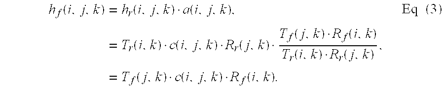
- The forward transfer functions, h f(i,j,k), for all propagation paths may then be used to form one or more channel response matrices Hf(k). Typically, one channel response metric Hf(k) is formed for each frequency subchannel. Each channel response matrix Hf(k) comprises an NT×NR matrix of forward transfer functions hf(i,j,k), where 1≦i≦NR and 1≦j≦NT, for the NT·NR transmit-receive antenna pairs for the k-th frequency subchannel. Each channel response matrix Hf(k) may then be used to derive weights, which are then used to precondition the modulation symbols for the k-th frequency subchannel, as described below.
- For each frequency subchannel, an eigenvector decomposition of a Hermitian matrix formed by the product of the channel response matrix H f with its conjugate-transpose Hf H can be expressed as:
- Hf HHf=EΛEH, Eq (4)
- where E is an eigenvector matrix and Λ is a diagonal matrix of eigenvalues, both of dimension N T×NT, and the symbol “H” denotes the conjugate-transpose. The base station preconditions a vector of NC modulation symbols, b, for each time slot using the eigenvector matrix E, as follows:
- x=Eb. Eq (5)
- The preconditioning in equation (5) can be more fully expressed as:

- where
- [b 1, b2, . . . bN
C ] are the modulation symbols forspatial subchannels 1, 2, . . . NC, respectively, where NC≦min {NT, NR}; - e ij are elements of the eigenvector matrix E, which is descriptive of the transmission characteristics from the base station antennas to the terminal antennas; and
- [x 1, x2, . . . xN
T ] are the preconditioned modulation symbols, which can be expressed as:
- Since H HH is Hermitian, the eigenvector matrix E is unitary. Thus, if the elements of the vector b have equal power, the elements of the vector x (i.e., the preconditioned modulation symbols) also have equal power.
- As shown in equations (5) and (6), for each frequency subchannel, the N C modulation symbols at each time slot are preconditioned to generate NT preconditioned modulation symbols. The preconditioning orthogonalizes the modulation symbol streams transmitted on the NC spatial subchannels, which may improve performance.
- FIG. 2 is a flow diagram of a process to derive the calibration function and to precondition modulation symbols prior to transmission on the forward link, in accordance with an embodiment of the invention. Initially (e.g., at the start of a communication session between a base station and a terminal), the terminal measures the forward transfer function, H f(ω), and sends it back to the base station, at
step 212. The base station also measures the reverse transfer function, Hr(ω), atstep 214. The forward and reverse transfer functions, Hf(ω) and Hr(ω), are then used by the base station to derive the calibration function, a(ω), as shown in equation (2), atstep 216.Steps 212 through 216 may be performed prior to the first data transmission from the base station to the terminal, and may also be performed thereafter as needed during the communication session. - A determination is then made whether or not there is a data transmission for the terminal, at
step 218. If there is no data to transmit, then the process returns to step 218 and waits (e.g., until the next time slot for the forward link). Otherwise, if there is data to transmit, the base station measures the reverse transfer function, Hr(ω), atstep 220. The base station then derives the forward transfer function, Hf(ω), based on the reverse transfer function, Hr(ω), and the calibration function, a(ω), as shown in equation (3), atstep 222. The forward transfer function, Hf(ω), is then used to process data prior to transmission to the terminal, atstep 224. More particularly, the forward transfer function, Hf(ω), is used to derive the eigenvector matrix E, as shown in equation (4), which is then used to precondition the modulation symbols, as shown in equations (5) and (6). The process then returns to step 218 and waits for the next data transmission (or the next time slot). - The received signals at the terminal may be expressed as:

- where n is the channel noise.
- To recover the transmitted modulation symbols, the terminal initially performs a channel-matched-filter operation, followed by a multiplication by the right eigenvector matrix. The result of the channel-matched-filter and multiplication operations is a vector y, which can be expressed as:

- where {circumflex over (n)} is the noise term after the receiver processing at the terminal. The channel response matrix, H f, for the forward link used to perform the channel-matched-filter operation may be determined at the terminal based on the pilot reference transmitted from the base station. As shown in equation (8), the resultant vector y is a scaled version of the vector b, which includes the modulation symbols prior to the preconditioning with the eigenvector matrix E at the base station. The scaling between the vectors b and y is based on the eigenvalues in the matrix Λ.
- The noise term {circumflex over (n)} after the receiver processing has a covariance that can be expressed as:

- where E{} is the expectation operation. From equation (9), the noise components for the spatial subchannels, after the receiver processing at the terminal, are independent with variances given by the eigenvalues. If the elements of b have equal power and if E{{circumflex over (n)}{circumflex over (n)} H}=I, then the SNR of the i-th component of the vector y (i.e., the i-th spatial subchannel) is λi, which is the i-th diagonal element of the matrix Λ of eigenvalues.
- Various schemes may be used to transmit a pilot reference from a transmitter unit (e.g., a terminal) to a receiver unit (e.g., a base station) to allow the receiver unit to characterize the communication link. The pilot reference is typically transmitted from all or a subset of the antennas at the transmitter unit and on a sufficient number of frequency subchannels such that an accurate characterization of the communication link can be made. The transmitted pilot reference is received by all antennas at the receiver unit and processed to characterize the link response.
- The particular pilot transmission scheme to be used may be selected based on various system constraints and considerations. The transmission scheme used for the reverse link may not be the same as that used for the forward link. As an example, the forward link may support MIMO whereas the reverse link may only support single-input multiple-output (SIMO), in which case the pilot transmission scheme should account for this difference. Some schemes for transmitting the pilot reference on the reverse link from the terminal to the base station are described below.
- In one pilot transmission scheme, the terminal transmits the pilot reference continuously (i.e., in all time slots allocated for the reverse link) from all antennas and on a sufficient number of subchannels. The pilot reference may be transmitted along with other packet data. For this scheme, the pilot reference is readily available to the base station for channel characterization at all times.
- If the pilot reference is transmitted from multiple antennas on a particular frequency subchannel (there may be only one frequency subchannel if OFDM is not employed) in a given time slot, then the pilot transmitted on different antennas should be orthogonal to each other. This would then allow the base station to recover the individual pilot reference transmitted on each antenna. In a single-carrier system, orthogonality may be achieved by transmitting the pilot on a different code channel from each antenna (e.g., covering the pilot data for each antenna with a different Walsh code).
- If OFDM is employed, the frequency response of the communication link may be determined for a subset of the frequency subchannels instead of all frequency subchannels. For example, if N F frequency subchannels and NR antennas are available at the terminal, then the pilot reference may be transmitted on NF/NR frequency subchannels of each of the NR antennas. The NF/NR frequency subchannels used for pilot transmission on each antenna are selected such that an accurate estimate of the frequency response may be made. For example, the pilot reference may be transmitted on frequency subchannels that are spaced over the entire frequency band and are NR channels apart. The NF/NR frequency subchannels for each antenna may be staggered (i.e., offset) relative to those of other antennas. In general, the number of frequency subchannels selected for pilot transmission for each antenna should be sufficient to allow for an accurate sampling of the spectrum of the communication link. The frequency domain sampling allows the forward link response to be estimated using fewer pilot transmissions.
- In another pilot transmission scheme, the terminal transmits a pilot reference in a time division multiplexed (TDM) manner from all antennas and on all or a subset of the frequency subchannels. For example, the pilot reference may be transmitted on all or a subset of the frequency subchannels from one antenna at each available time slot in a sequential manner (e.g., in a round-robin manner). Thus, the pilot reference may be transmitted from
antenna 1 at a particular time slot, from antenna 2 at the next available time slot, and so on. Numerous other TDM schemes may also be used to transmit the pilot reference from the terminal. - In yet another pilot transmission scheme, multiple terminals are able to concurrently transmit pilot references at the same time via code division multiplexing (CDM). For example, terminal 1 may transmit the pilot reference on a first set of code channels (from all or a subset of the antennas), terminal 2 may transmit the pilot reference on a second set of code channels, and so on. The code channels are designed to be orthogonal to each other so that the pilot references from different terminals can be individually recovered at the base station, which then allows the base station to characterize the forward link response for each of the terminals.
- In yet another pilot transmission scheme, multiple terminals are able to concurrently transmit pilot references at the same time via time division multiplexing (TDM). In an implementation, one terminal may be designated to transmit pilot reference on the reverse link at any given time slot. In a first embodiment, the pilot transmissions on the reverse link are scheduled by the base station using a scheme such as polling. Whenever the base station needs to transmit data to a particular terminal, that terminal is notified prior to the data transmission. The terminal then transmits pilot reference on all or a subset of the frequency subchannels and from all or a subset of the antennas to allow the base station to characterize the forward link for this terminal. In a second embodiment, the terminals are assigned fixed time slots for pilot transmission. For example, terminal 1 may be assigned to transmit the pilot reference in every n-th time slot starting with a particular time slot (from all or a subset of the antennas and on all or a subset of the frequency subchannels), terminal 2 may be assigned to transmit the pilot reference on every n-th time slot starting with the next available time slot, and so on. For TDM pilot transmission schemes, the time slots are assigned to the terminals such that the forward link can be characterized a close to the time of actual data transmission on the forward link. In this way, accurate forward link characterization may be obtained.
- In yet another pilot transmission scheme, multiple terminals are able to concurrently transmit pilot references at the same time via frequency division multiplexing (FDM). For example, at time slot n, terminal 1 may transmit the pilot reference on frequency subchannel 1 (from all or a subset of the antennas), terminal 2 may transmit the pilot reference on frequency subchannel 2, and so on.
- As described above, the forward link frequency response for each terminal may be sampled using a subset of the frequency subchannels. For example, N X terminals may be designated to transmit pilot references on NF frequency subchannels, and each terminal may be allocated NF/NX frequency subchannels for pilot transmission. The NF/NX frequency subchannels for each terminal are selected such that an accurate estimate of the frequency response may be made. The pilot reference may be transmitted on frequency subchannels that are spaced over the entire frequency band and are NX channels apart.
- Using the techniques described above, the base station is able to characterize the response of the forward link based on the pilot reference transmitted by the terminal. This characterization typically includes estimates of the frequency response for the communication link (e.g., the MIMO channel). This information may be used to orthogonalize the spatial subchannels, as described above.
- In some other embodiments, the forward link is characterized at the terminal based on the pilot transmitted from the base station. The forward link characterization is then sent back to the base station, which then uses the information to process data (e.g., precondition the modulation symbols) for the forward link transmissions.
- In accordance with another aspect of the invention, the terminal estimates the “quality” of the forward link and provides this information to the base station. The forward link quality may be quantified by the SNR, the noise-plus-interference, or some other measurement. The SNR may be estimated for each transmission channel, each transmit-receive antenna pair, or for groups of these transmission channels or antenna pairs. The forward link quality may be estimated based on the pilot reference, data, or some other signals transmitted on the forward link. The forward link quality estimate is then represented in a particular form and sent to the base station, which then uses the information to properly code and modulate data prior to transmission such that the transmitted data can be received by the terminal at the desired level of performance (e.g., 1% PER).
- In an embodiment, one coding and modulation scheme is used for all transmission channels to be used for the forward link transmission. In this case, the terminal can estimate the average SNR across all transmission channels and report this average SNR to the base station. For example, the terminal can process the pilot reference received on each antenna and estimate the SNR for each propagation path, and may further derive the average SNR from the individual SNRs. Reporting the average SNR instead of the individual SNRs can significantly reduce the amount of information to be sent back to the base station.
- In another embodiment, a number of data streams may be transmitted on a number of groups of transmission channels. Each data stream may be independently processed (i.e., coded and modulated) with a particular coding and modulation scheme, or multiple data streams may share a common coding and modulation scheme. Each group of channels may include any number and type of transmission channels. For example, one group may be defined for each antenna at the base station, with each group including all frequency subchannels for the associated antenna. As another example, one group may be defined for each frequency subchannel, with each group including all spatial subchannels for the associated frequency subchannel. As yet another example, one group may be defined for each different subset of frequency subchannels, with each group including all spatial subchannels for the associated frequency subchannels. Alternatively, each group may include one transmission channel.
- The forward link quality may be reported to the base station via various forms. In an embodiment, the SNRs for the individual transmission channels or an average SNR for each group of channels may be determined and reported. In another embodiment, the terminal can map the estimated SNR to a particular rate (e.g., a data rate indicator (DRI)) and send the rate information back to the base station. The rate indicator may be indicative of the maximum data rate that may be transmitted on the corresponding group of transmission channels for the required level of performance. In yet another embodiment, the terminal may report an indication of a particular coding and modulation scheme to be used by the base station for each data stream to be independently processed. In yet another embodiment, the noise or interference power for all or a single frequency subchannel, the average channel noise variance, or some other measurement, may be reported. Various other forms may also be used to report the forward link quality and are within the scope of the invention. In general, the terminal may report any type of information that can be used at the base station to properly code and modulate data prior to transmission on the forward link.
- The terminal can thus estimate the forward link quality for each group of transmission channels and report information indicative of the estimated quality (e.g., the average SNR, a rate indicator, or an indication of a coding and modulation scheme) to the base station. By reporting information for each group, the base station is able to individually and independently code and modulate each data stream based on the received information for the associated group of transmission channels, which may provide improved performance. For example, the base station may be able to transmit different data streams on different antennas, with each data stream having a particular bit rate supported by the transmission channels used to transmit the data stream.
- In certain embodiments, the forward link quality can be estimated at the base station based on the pilot reference transmitted by the terminal. Because the forward and reverse links are reciprocal, the quality of the forward link can be estimated based on the quality of the reverse link, which can be estimated by the base station. Initially, the base station can estimate the SNR (e.g., average SNR ) for the reverse link based on the pilot reference transmitted by the terminal (i.e., the same pilot reference used to derive the reverse channel response matrix H r at the base station). The base station is able to estimate the channel noise variance.
- As shown in equation (8), the vector z recovered at the terminal is equal to the vector b scaled by the eigenvalues in the matrix Λ. The matrix Λ can also be derived at the base station based on the forward channel response matrix H f. The base station can thus estimate the signal power at the terminal (based on the matrix Λ and the vector b). The SNR at the terminal is then estimated based on the signal power and the channel noise variance computed at the base station. The estimated SNR can then be used to properly code and modulate the data.
- For the embodiments wherein the forward link quality is estimated at the base station, the coding and modulation scheme(s) selected for use by the base station may be sent to the terminal so that it can use the corresponding demodulation and decoding scheme(s) to recover the transmitted data. Alternatively, the terminal may perform “blind” decoding whereby it processes the received signals based on a number of hypotheses corresponding to a number of possible coding and modulation schemes.
- Various techniques may be used to estimate the link quality. Some of these techniques are described in the following patents, which are all assigned to the assignee of the present application and incorporated herein by reference:
- U.S. Pat. No. 5,799,005, entitled “SYSTEM AND METHOD FOR DETERMINING RECEIVED PILOT POWER AND PATH LOSS IN A CDMA COMMUNICATION SYSTEM,” issued Aug. 25, 1998,
- U.S. Pat. No. 5,903,554, entitled “METHOD AND APPARATUS FOR MEASURING LINK QUALITY IN A SPREAD SPECTRUM COMMUNICATION SYSTEM,” issued May 11, 1999,
- U.S. Pat. Nos. 5,056,109, and 5,265,119, both entitled “METHOD AND APPARATUS FOR CONTROLLING TRANSMISSION POWER IN A CDMA CELLULAR MOBILE TELEPHONE SYSTEM,” respectively issued Oct. 8, 1991 and Nov. 23, 1993, and
- U.S. Pat. No. 6,097,972, entitled “METHOD AND APPARATUS FOR PROCESSING POWER CONTROL SIGNALS IN CDMA MOBILE
- TELEPHONE SYSTEM,” issued Aug. 1, 2000.
- Methods for estimating a single transmission channel based on a pilot reference or a data transmission may also be found in a number of papers available in the art. One such channel estimation method is described by F. Ling in a paper entitled “Optimal Reception, Performance Bound, and Cutoff-Rate Analysis of References-Assisted Coherent CDMA Communications with Applications,” IEEE Transaction On Communication, October 1999, and incorporated herein by reference.
- FIGS. 3A and 3B show a block diagram of a specific design of a
transmitter unit 110 a at a base station, which utilizes MIMO and OFDM and is capable of processing data in accordance with an embodiment of the invention.Transmitter unit 110 a includes aTX data processor 114 a that receives and processes information bits to provide modulation symbols, aTX channel processor 120 a that preconditions the modulation symbols, and a number of modulators 122 that process the preconditioned modulation symbols to generate a number of modulated signals suitable for transmission to the terminal. - In the embodiment shown in FIG. 3A,
TX data processor 114 a includes a number ofdata stream processors 310 a through 310 n, one data stream processor 310 for each data stream to be independently coded and modulated. (One data stream may be transmitted on all transmission channels, on each group of transmission channels, or on each transmission channel.) Each data stream processor 310 includes anencoder 312, aninterleaver 314, achannelizer 316, and asymbol mapping element 318.Encoder 312 receives the information bits for a particular data stream and encodes the received bits in accordance with a particular encoding scheme to provide coded bits.Channel interleaver 314 interleaves the coded bits based on a particular interleaving scheme to provide diversity. - Pilot data (e.g., data of a known pattern) may also be multiplexed with the processed information bits. The pilot data may be transmitted using any one of the pilot transmission schemes described above. The pilot reference may be used at the terminal to characterize the forward link and to estimate the link quality, as described above.
- If code division multiplexing is utilized,
channelizer 316 receives and channelizes the interleaved packet data and the pilot data on their assigned code channels.Symbol mapping element 318 then maps the channelized packet and pilot data into modulation symbols for the selected transmission channels. - As shown in FIG. 3A, the data encoding and interleaving by each data stream processor 310 may be achieved based on a respective coding control that identifies the specific coding and interleaving schemes to be used for the data stream. The symbol mapping by each data stream processor 310 may also be achieved based on a respective modulation control that identifies the specific modulation scheme to be used for the data stream. The specific coding and modulation scheme used for each data stream may be selected based on the forward link quality (e.g., as reported by the terminal)
- In one type of coding and modulation scheme, the coding for each data stream is achieved by using a fixed base code and adjusting the puncturing to achieve the desired code rate, as supported by the SNRs of the transmission channels used to transmit the data stream. The base code may be a Turbo code, a convolutional code, a concatenated code, or some other code. The base code may also be of a particular rate (e.g., a rate ⅓code). For this type of scheme, the puncturing may be performed after the interleaving to achieve the desired code rate.
-
Symbol mapping element 318 can be designed to group sets of channelized bits to form non-binary symbols, and to map each non-binary symbol into a point in a signal constellation corresponding to the modulation scheme selected for use. The modulation scheme may be QPSK, M-PSK, M-QAM, or some other scheme. Each mapped signal point corresponds to a modulation symbol. One modulation scheme may be selected for each transmission channel used to transmit the data stream, or a common modulation scheme may be used for all transmission channels used to transmit the data stream. - The encoding, interleaving, and symbol mapping at
transmitter unit 110 a can be performed based on numerous schemes. Some coding and modulation schemes are described in the following patent applications, which are all assigned to the assignee of the present application and incorporated herein by reference: - U.S. patent application Ser. No. 09/532,492, entitled “HIGH EFFICIENCY, HIGH PERFORMANCE COMMUNICATIONS SYSTEM EMPLOYING MULTI-CARRIER MODULATION,” filed Mar. 22, 2000;
- U.S. patent application Ser. No. 09/776,075, entitled “CODING SCHEME FOR A WIRELESS COMMUNICATION SYSTEM,” filed Feb. 1, 2001;
- U.S. patent application Ser. No. 09/826,481, “METHOD AND APPARATUS FOR UTILIZING CHANNEL STATE INFORMATION IN A WIRELESS COMMUNICATION SYSTEM,” filed Mar. 23, 2001; and
- U.S. patent application Ser. No. 09/854,235, entitled “METHOD AND APPARATUS FOR PROCESSING DATA IN A MULTIPLE-INPUT MULTIPLE-OUTPUT (MIMO) COMMUNICATION SYSTEM UTILIZING CHANNEL STATE INFORMATION,” filed May 11, 2001.
- The modulation symbols from
TX data processor 114 a are provided toTX channel processor 120 a, which is one embodiment ofTX channel processor 120 in FIG. 1. WithinTX channel processor 120 a, a multiplexer/demultiplexer 322 receives and demultiplexes the modulation symbol fromdata stream processors 310 a through 310 n to theproper MIMO processors 324 a through 324 l. One MIMO processor 324 is provided to perform the preconditioning for each frequency subchannel. - Each MIMO processor 324 receives a stream of modulation symbols for the spatial subchannels of a particular frequency subchannel assigned to the MIMO processor. Each MIMO processor 324 further receives an eigenvector matrix E(k) for the frequency subchannel, which is a matrix of weights derived from the channel response matrix Hf(k). Each MIMO processor 324 then preconditions the modulation symbols with the eigenvector matrix E(k), as shown in equations (5) and (6), to generate the preconditioned modulation symbols.
- The preconditioned modulation symbols from
MIMO processors 324 a through 3241 are provided tocombiners 326 a through 326 t. One combiner 326 is provided for each antenna at the base station. Each combiner 326 receives and combines up to NF preconditioned modulation symbols for NF frequency subchannels for a particular antenna to form a modulation symbol vector V. -
TX channel processor 120 a thus receives and processes the modulation symbols to provide up to NT modulation symbol vectors, V1 through VNt, one modulation symbol vector for each antenna for data transmission. Each modulation symbol vector V covers a single time slot, and each element of the modulation symbol vector V is associated with a specific frequency subchannel having a unique subcarrier on which the modulation symbol is conveyed. - FIG. 3B is a block diagram of an embodiment of modulators 122 for OFDM. The modulation symbol vectors V1 through VNt from
TX channel processor 120 a are provided to modulators 122 a through 122 t, respectively. In the embodiment shown in FIG. 3B, each modulator 122 includes an inverse Fast Fourier Transform (IFFT) 340, a cyclic prefix generator 342, and an upconverter 344. - IFFT 340 converts each received modulation symbol vector V into its time-domain representation (which is referred to as an OFDM symbol) using IFFT. IFFT 340 can be designed to perform the IFFT on any number of frequency subchannels (e.g., 8, 16, 32, . . . , or NF). In an embodiment, for each modulation symbol vector converted to an OFDM symbol, cyclic prefix generator 342 repeats a portion of the time-domain representation of the OFDM symbol to form a “transmission symbol” for a specific antenna. The cyclic prefix insures that the transmission symbol retains its orthogonal properties in the presence of multipath delay spread, thereby improving performance against deleterious path effects. The cyclic prefix is selected to be sufficiently long relative to the expected amount of delay spread. The implementation of IFFT 340 and cyclic prefix generator 342 is known in the art and not described in detail herein.
- The time-domain representations from each cyclic prefix generator 342 (i.e., the transmission symbols for each antenna) are further processed (e.g., converted into an analog signal, modulated, amplified, and filtered) by upconverter 344 to generate a modulated signal suitable for transmission over the forward link. The modulated signal generated by each modulator 122 is then transmitted from an associated antenna 124.
- OFDM modulation is described in further detail in a paper entitled “Multicarrier Modulation for Data Transmission: An Idea Whose Time Has Come,” by John A. C. Bingham, IEEE Communications Magazine, May 1990, which is incorporated herein by reference.
- FIG. 4 is a block diagram of a specific design of a
receiver unit 150 a of a terminal, which is capable of receiving data in accordance with an embodiment of the invention. The transmitted signals from NT antennas at the base station are received by each of NR antennas 152 a through 152 r at the terminal and routed to a respective demodulator 154. Each demodulator 154 conditions, processes, and digitizes the respective received signal to provide samples, which are provided to aRX channel processor 156 a. - Within
RX channel processor 156 a, the samples for each receive antenna 152 are provided to a respective FFT processor 406, which generates transformed representations of the received samples and provides a respective stream of modulation symbol vectors. The NR streams of modulation symbol vectors fromFFT processors 406 a through 406 r are then provided to multiplexer/demultiplexer 408, which first demultiplexes the stream of modulation symbol vectors from each FFT processor 406 into NF streams of modulation symbols, one stream for each of the NF frequency subchannels. Multiplexer/demultiplexer 408 then multiplexes the NR streams of modulation symbols for each frequency subchannel into a stream of modulation symbol vector, r, with each vector in the stream including NR modulation symbols for the NR antennas. Multiplexer/demultiplexer 408 provides the NF streams of modulation symbol vectors, one stream at a time, to aspatial processor 410. - For each frequency subchannel, a
match filter 412 withinspatial processor 410 filters the modulation symbol vector stream r by performing a pre-multiplication with the conjugate-transpose channel response matrix Hf H, as shown above in equation (8). The channel coefficient matrix Hf for the forward link may be estimated by achannel estimator 416 based on the pilot reference transmitted from the base station. An eigenvector matrix E is then derived by amatrix processor 418 based on the channel coefficient matrix Hf, as shown in equation (4). The filtered vectors frommatch filter 412 are further pre-multiplied by amultiplier 414 with the conjugate-transpose eigenvector matrix EH to generate the vectors of recovered modulation symbols y, as shown in equation (8). - A
selector 420 receives the vectors of recovered modulation symbols, y, and extracts the modulation symbols corresponding to a particular data stream to be recovered.Selector 420 may then provide a number of symbol streams, z, corresponding to a number of data streams to be recovered by the terminal. Each symbol stream z includes recovered modulation symbols that correspond to, and are estimates of, the modulation symbols b after the symbol mapping (but prior to the preconditioning) at the base station for a particular data stream. Each recovered symbol stream z is then provided to aRX data processor 158 a. - Within
RX data processor 158 a, the stream of recovered modulation symbols for a particular data stream is demodulated by ademodulation element 432 in accordance with a demodulation scheme (e.g., M-PSK, M-QAM) that is complementary to the modulation scheme used for the data stream.Demodulation element 432 further performs decovering of the demodulated data, if the data is channelized at the base station by covering with orthogonal codes. The demodulated data is then de-interleaved by a de-interleaver 434 in a complementary manner to that performed byinterleaver 314, and the de-interleaved data is further decoded by adecoder 436 in a complementary manner to that performed byencoder 312. For example, a Turbo decoder or a Viterbi decoder may be used fordecoder 436 if Turbo or convolutional coding, respectively, is performed at the base station. The decoded data stream fromdecoder 436 represents an estimate of the transmitted data stream being recovered. - A
CSI processor 422 receives the pilot and/or data transmission and estimates the forward link quality, as described above. For example,CSI processor 422 may compute a noise covariance matrix based on the received data and/or pilot and may further compute the SNR of a transmission channel. The SNR may be estimated similar to conventional pilot assisted single and multi-carrier systems, as is known in the art. The frequency response for all propagation paths (i.e., Hf) derived bychannel estimator 416 and the forward link quality (e.g., the SNR) estimated byCSI processor 422 may comprise the CSI that is reported by the terminal to the base station. The CSI is then provided to a TX data processor 162 (see FIG. 1) for transmission back to the base station. - Referring back to FIG. 1, the CSI (e.g., H f and/or SNR) determined by
RX channel processor 156 is provided toTX data processor 162, which processes the CSI based on a particular processing scheme.TX data processor 162 further receives and process pilot data for transmission from one or more antennas and on one or more frequency subchannels. The processed CSI and pilot are then received and further processed by aTX channel processor 164 and then provided to one or more modulators 154. Modulators 154 further condition and transmit the CSI and pilot on the reverse link to the base station. - At the base station, the CSI and pilot transmitted on the reverse link are received by antennas 124, demodulated by demodulators 122, and provided to a
RX channel processor 132.RX channel processor 132 processes the received pilot to derive the channel response matrix Hr for the reverse link.RX channel processor 132 and aRX data processor 134 also process the received data in a complementary manner to that performed byTX channel processor 164 andTX data processor 162 to recover the - A
controller 136 uses the recovered CSI to perform a number of functions including (1) determining the coding and modulation scheme to be used for each data stream, (2) deriving the eigenvector matrix E to be used to precondition the modulation symbols, and (3) computing the calibration function a(ω).Controller 136 then provides the coding and modulation control toTX data processor 114 and the preconditioning control toTX channel processor 120, as shown in FIG. 3A. - In the above description, the modulation symbols are preconditioned at the transmitter system based on the eigenvector matrix E derived from the channel response matrix H f for the forward link. In certain embodiments or for certain transmissions in which the channel response matrix Hf is not available, the modulation symbols may be transmitted without preconditioning. In this case, linear spatial processing may be performed on the received symbols (for a non-dispersive MIMO channel with flat fading) or space-time processing may be performed (for a dispersive MIMO channel with frequency selective fading) at the terminal to null out the undesired signals and to maximize the received SNR of each of the constituent signals in the presence of noise and interference from other signals. The ability to effectively null undesired signals or optimize SNR depends upon the correlation in the channel response matrix Hf.
- The spatial processing may be achieved using linear spatial processing techniques such as a channel correlation matrix inversion (CCMI) technique, a minimum mean square error (MMSE) technique, and others. The space-time processing may be achieved using linear space-time processing techniques such as a MMSE linear equalizer (MMSE-LE), a decision feedback equalizer (DFE), a maximum-likelihood sequence estimator (MLSE), and others. The CCMI, MMSE, MMSE-LE, and DFE techniques are described in further detail in the aforementioned U.S. patent application Ser. Nos. 09/826,481 and 09/854,235.
- For clarity, various aspects have been described for data transmission on the forward link from the base station to the terminal. The techniques described herein may also be applied for data transmission on the reverse link from the terminal to the base station.
- The elements of the base station (e.g., as shown in FIGS. 1, 3A, and 3B) and the elements of the terminal (e.g., as shown in FIGS. 1 and 4) may each be implemented with one or more digital signal processors (DSPs), application specific integrated circuits (ASICs), processors, microprocessors, controllers, microcontrollers, field programmable gate arrays (FPGAs), programmable logic devices, other electronic units, or any combination thereof. Some of the functions and processing described herein may also be implemented with software executed on a processor. Certain aspects of the invention may also be implemented with a combination of software and hardware. For example, the computations to determine the channel response matrix Hf and the eigenvector matrix E and the preconditioning at the base station may be performed based on program codes executed on a processor (e.g.,
controller 136 in FIG. 1). Similarly, the computations to determine the channel response matrix Hf and the eigenvector matrix E and the receiver processing at the terminal may be performed based on program codes executed on a processor. - Headings are included herein for reference and to aid in locating certain sections. These headings are not intended to limit the scope of the concepts described therein under, and these concepts may have applicability in other sections throughout the entire specification.
- The previous description of the disclosed embodiments is provided to enable any person skilled in the art to make or use the present invention. Various modifications to these embodiments will be readily apparent to those skilled in the art, and the generic principles defined herein may be applied to other embodiments without departing from the spirit or scope of the invention. Thus, the present invention is not intended to be limited to the embodiments shown herein but is to be accorded the widest scope consistent with the principles and novel features disclosed herein.
Claims (35)
1. In a time division duplexed (TDD) communication system, a method for transmitting data from a transmitter unit over a wireless communication link to a receiver unit, the method comprising:
receiving via the communication link a first transmission from the receiver unit;
estimating characteristics of the communication link based on the received first transmission;
coding and modulating the data based on one or more coding and modulation schemes to provide modulation symbols;
preconditioning the modulation symbols based on weights derived at least in part from the estimated characteristics of the communication link; and
transmitting the preconditioned modulation symbols from the transmitter unit via the communication link to the receiver unit.
2. The method of claim 1 , further comprising:
deriving a calibration function indicative of a difference between a first transfer function for a data transmission from the transmitter unit to the receiver unit and a second transfer function for a data transmission from the receiver unit to the transmitter unit, and
wherein the weights are further derived based on the calibration function.
3. The method of claim 2 , wherein the first transfer function is derived at the receiver unit and provided to the transmitter unit.
4. The method of claim 1 , further comprising:
transmitting pilot reference from the transmitter unit via the communication link to the receiver unit.
5. The method of claim 1 , wherein the TDD communication system implements orthogonal frequency division modulation (OFDM), and wherein the communication link comprises a plurality of frequency subchannels.
6. The method of claim 1 , wherein the TDD communication system implements multiple-input multiple-output (MIMO), and wherein the communication link comprises a plurality of spatial subchannels.
7. The method of claim 6 , wherein the TDD communication system further implements OFDM.
8. The method of claim 1 , wherein the communication link comprises a plurality of propagation paths, each propagation path corresponding to a path between a particular antenna at the transmitter unit and a particular antenna at the receiver unit.
9. The method of claim 8 , wherein the estimated characteristics of the communication link relate to frequency response of the propagation paths used to transmit the data to the receiver unit.
10. The method of claim 1 , wherein the first transmission from the receiver unit is a pilot reference.
11. The method of claim 5 , wherein the first transmission from the receiver unit is a pilot reference transmitted over all frequency subchannels.
12. The method of claim 5 , wherein the first transmission from the receiver unit is a pilot reference transmitted over a subset of all frequency subchannels.
13. The method of claim 6 , wherein the first transmission from the receiver unit is a pilot reference transmitted from all antennas at the receiver unit.
14. The method of claim 6 , wherein the first transmission from the receiver unit is a pilot reference transmitted from a subset of all antennas at the receiver unit in each particular time slot.
15. The method of claim 6 , wherein the first transmission from the receiver unit is a pilot reference transmitted from one or more antennas at the receiver unit, and wherein the pilot reference is transmitted on a different code channel for each of the one or more antennas.
16. The method of claim 1 , further comprising:
receiving an indication of a quality of the communication link, and
wherein the one or more coding and modulation schemes are selected based on the received indication of the communication link quality.
17. The method of claim 1 , wherein the data is transmitted via a plurality of data streams, and wherein each data stream is coded and modulated with a respective coding and modulation scheme.
18. The method of claim 16 , wherein the communication link quality is estimated at the receiver unit and provided to the transmitter unit.
19. The method of claim 16 , wherein the communication link quality is estimated at the transmitter unit.
20. The method of claim 16 , wherein the received indication is indicative of a signal-to-noise-plus-interference ratio (SNR).
21. The method of claim 20 , wherein an average SNR is received for each data stream to be independently coded and modulated.
22. The method of claim 16 , wherein the received indication is indicative of a particular rate to be used for each data stream to be independently coded and modulated.
23. The method of claim 16 , wherein the received indication is indicative of a particular coding and modulation scheme to be used for each data stream to be independently coded and modulated.
24. In a time division duplexed (TDD) communication system, a method for transmitting data from a transmitter unit over a wireless communication link to a receiver unit, the method comprising:
deriving a calibration function indicative of a difference between a first transfer function for a data transmission from the transmitter unit to the receiver unit and a second transfer function for a data transmission from the receiver unit to the transmitter unit;
receiving via the communication link a first transmission from the receiver unit;
estimating characteristics of the communication link based on the received first transmission;
coding and modulating the data based on one or more coding and modulation schemes to provide modulation symbols;
preconditioning the modulation symbols based on weights derived from the estimated characteristics of the communication link and the calibration function; and
transmitting the preconditioned modulation symbols from the transmitter unit via the communication link to the receiver unit.
25. The method of claim 24 , wherein the TDD communication system implements multiple-input multiple-output (MIMO) and orthogonal frequency division modulation (OFDM).
26. A transmitter unit in a time division duplexed (TDD) communication system, comprising:
a receiver processor operative to receive via a communication link a first transmission from a receiver unit and to estimate characteristics of the communication link based on the received first transmission;
a transmit data processor operative to code and modulate data based on one or more coding and modulation schemes to provide modulation symbols;
a transmit channel processor operative to receive and precondition the modulation symbols based on weights derived at least in part from the estimated characteristics of the communication link; and
a modulator operative to receive, condition, and transmit the preconditioned modulation symbols via the communication link to the receiver unit.
27. The transmitter unit of claim 26 , further comprising:
a controller operative to provide a first control indicative of the one or more coding and modulation schemes used to code and modulate the data and a second control indicative of the weights used to precondition the modulation symbols.
28. The transmitter unit of claim 27 , wherein the controller is further operative to derive a calibration function indicative of a difference between a first transfer function for a data transmission from the transmitter unit to the receiver unit and a second transfer function for a data transmission from the receiver unit to the transmitter unit, and wherein the weights are further derived based on the calibration function
29. The transmitter unit of claim 26 , wherein the transmit data processor is further operative to process pilot data for transmission via the communication link to the receiver unit.
30. A receiver unit in a time division duplexed (TDD) communication system, comprising:
one or more antennas, each antenna configured to receive via a communication link one or more modulated signals transmitted from a transmitter unit;
one or more front-end units, each front-end unit operative to process a signal from an associated antenna to provide a respective stream of received modulation symbols;
a spatial processor operative to receive and process the one or more streams of received modulation symbols to provide estimated characteristics of the communication link and to further process the received modulation symbols based at least in part on the estimated characteristics of the communication link to provide one or more streams of recovered modulation symbols; and
a receive data processor operative to receive and decode the one or more streams of recovered modulation symbols to provide one or more decoded data streams.
31. The receiver unit of claim 30 , further comprising:
a channel state information (CSI) processor operative to estimate the quality of the communication link based on the recovered modulation symbols; and
a transmit data processor operative to receive and process the estimated communication link quality for transmission from the receiver unit to the transmitter unit.
32. The receiver unit of claim 30 , further comprising:
a transmit processor operative to process pilot data for transmission from the receiver unit to the transmitter unit.
33. The receiver unit of claim 32 , wherein the transmit processor is further operative to transmit the estimated characteristics of the communication link from the receiver unit to the transmitter unit.
34. The receiver unit of claim 30 , wherein the spatial processor is operative to match filter the received modulation symbols based on a channel response matrix indicative of the estimated characteristics of the communication link and to multiply the filtered modulation symbols with a eigenvector matrix to provide the recovered modulation symbols.
35. The receiver unit of claim 30 , wherein the one or more modulated signals are generated at the transmitter unit by
coding and modulating the data based on one or more coding and modulation schemes to provide modulation symbols,
preconditioning the modulation symbols based on weights derived from estimated characteristics of the communication link derived at the transmitter unit, and
processing the preconditioned modulation symbols to provide the one or more modulated signals, one modulated signal for each antenna at the transmitter unit.
Priority Applications (17)
| Application Number | Priority Date | Filing Date | Title |
|---|---|---|---|
| US09/887,225 US7027523B2 (en) | 2001-06-22 | 2001-06-22 | Method and apparatus for transmitting data in a time division duplexed (TDD) communication system |
| BR0210559-4A BR0210559A (en) | 2001-06-22 | 2002-06-17 | Method and equipment for transmitting data in a time division duplex system |
| KR1020037016722A KR100897138B1 (en) | 2001-06-22 | 2002-06-17 | Method and apparatus for transmitting data in a time division duplex system |
| EP10179536A EP2264965A3 (en) | 2001-06-22 | 2002-06-17 | Method and apparatus for generating a calibration function in a wireless communication system |
| JP2003508034A JP2004534456A (en) | 2001-06-22 | 2002-06-17 | Method and apparatus for transmitting data in a time division duplex system |
| EP02739928A EP1402699A1 (en) | 2001-06-22 | 2002-06-17 | Method and apparatus for transmitting data in a time division duplex system |
| CNB028154312A CN1309231C (en) | 2001-06-22 | 2002-06-17 | Method and apparatus for transmitting data in time division duplex system |
| PCT/US2002/019404 WO2003001761A1 (en) | 2001-06-22 | 2002-06-17 | Method and apparatus for transmitting data in a time division duplex system |
| KR1020087023880A KR100918882B1 (en) | 2001-06-22 | 2002-06-17 | Method and apparatus for transmitting data in a time division duplex system |
| TW091113639A TWI238631B (en) | 2001-06-22 | 2002-06-21 | Method and apparatus for transmitting data in a time division duplexed (TDD) communication system |
| HK04110268A HK1067475A1 (en) | 2001-06-22 | 2004-12-28 | Method and apparatus for transmitting data in a time division duplex system |
| US11/328,807 US7333560B2 (en) | 2001-06-22 | 2006-01-09 | Method and apparatus for transmitting data in a time division duplexed (TDD) communication system |
| US11/963,016 US7729444B2 (en) | 2001-06-22 | 2007-12-21 | Method and apparatus for transmitting data in a time division duplexed (TDD) communication system |
| US12/547,732 US8121217B2 (en) | 2001-06-22 | 2009-08-26 | Method and apparatus for transmitting data in a time division duplexed (TDD) communication system |
| JP2009250647A JP2010093822A (en) | 2001-06-22 | 2009-10-30 | Method and apparatus for transmitting data in time division duplex system |
| JP2012089397A JP2012182800A (en) | 2001-06-22 | 2012-04-10 | Method and apparatus for transmitting data in time division duplexed system |
| JP2013050563A JP5485439B2 (en) | 2001-06-22 | 2013-03-13 | Method and apparatus for transmitting data in a time division duplex system |
Applications Claiming Priority (1)
| Application Number | Priority Date | Filing Date | Title |
|---|---|---|---|
| US09/887,225 US7027523B2 (en) | 2001-06-22 | 2001-06-22 | Method and apparatus for transmitting data in a time division duplexed (TDD) communication system |
Related Child Applications (1)
| Application Number | Title | Priority Date | Filing Date |
|---|---|---|---|
| US11/328,807 Continuation US7333560B2 (en) | 2001-06-22 | 2006-01-09 | Method and apparatus for transmitting data in a time division duplexed (TDD) communication system |
Publications (2)
| Publication Number | Publication Date |
|---|---|
| US20030002450A1 true US20030002450A1 (en) | 2003-01-02 |
| US7027523B2 US7027523B2 (en) | 2006-04-11 |
Family
ID=25390711
Family Applications (4)
| Application Number | Title | Priority Date | Filing Date |
|---|---|---|---|
| US09/887,225 Expired - Lifetime US7027523B2 (en) | 2001-06-22 | 2001-06-22 | Method and apparatus for transmitting data in a time division duplexed (TDD) communication system |
| US11/328,807 Expired - Lifetime US7333560B2 (en) | 2001-06-22 | 2006-01-09 | Method and apparatus for transmitting data in a time division duplexed (TDD) communication system |
| US11/963,016 Expired - Fee Related US7729444B2 (en) | 2001-06-22 | 2007-12-21 | Method and apparatus for transmitting data in a time division duplexed (TDD) communication system |
| US12/547,732 Expired - Fee Related US8121217B2 (en) | 2001-06-22 | 2009-08-26 | Method and apparatus for transmitting data in a time division duplexed (TDD) communication system |
Family Applications After (3)
| Application Number | Title | Priority Date | Filing Date |
|---|---|---|---|
| US11/328,807 Expired - Lifetime US7333560B2 (en) | 2001-06-22 | 2006-01-09 | Method and apparatus for transmitting data in a time division duplexed (TDD) communication system |
| US11/963,016 Expired - Fee Related US7729444B2 (en) | 2001-06-22 | 2007-12-21 | Method and apparatus for transmitting data in a time division duplexed (TDD) communication system |
| US12/547,732 Expired - Fee Related US8121217B2 (en) | 2001-06-22 | 2009-08-26 | Method and apparatus for transmitting data in a time division duplexed (TDD) communication system |
Country Status (9)
| Country | Link |
|---|---|
| US (4) | US7027523B2 (en) |
| EP (2) | EP1402699A1 (en) |
| JP (4) | JP2004534456A (en) |
| KR (2) | KR100918882B1 (en) |
| CN (1) | CN1309231C (en) |
| BR (1) | BR0210559A (en) |
| HK (1) | HK1067475A1 (en) |
| TW (1) | TWI238631B (en) |
| WO (1) | WO2003001761A1 (en) |
Cited By (76)
| Publication number | Priority date | Publication date | Assignee | Title |
|---|---|---|---|---|
| US20030043893A1 (en) * | 2001-06-06 | 2003-03-06 | Alexandre Jard | Signal processing method and apparatus for a spread spectrum radio communication receiver |
| US20030165187A1 (en) * | 2002-03-01 | 2003-09-04 | Cognio, Inc. | System and Method for Joint Maximal Ratio Combining Using Time-Domain Based Signal Processing |
| US6687492B1 (en) * | 2002-03-01 | 2004-02-03 | Cognio, Inc. | System and method for antenna diversity using joint maximal ratio combining |
| US20040023621A1 (en) * | 2002-07-30 | 2004-02-05 | Sugar Gary L. | System and method for multiple-input multiple-output (MIMO) radio communication |
| US20040042556A1 (en) * | 2002-08-27 | 2004-03-04 | Irina Medvedev | Coded MIMO systems with selective channel inversion applied per eigenmode |
| US20040072546A1 (en) * | 2002-03-01 | 2004-04-15 | Cognio, Inc. | System and Method for Antenna Diversity Using Equal Power Joint Maximal Ratio Combining |
| US20040082356A1 (en) * | 2002-10-25 | 2004-04-29 | Walton J. Rodney | MIMO WLAN system |
| WO2004039022A2 (en) * | 2002-10-25 | 2004-05-06 | Qualcomm, Incorporated | Correction for differences between downlink and uplink channel responses |
| US20040120411A1 (en) * | 2002-10-25 | 2004-06-24 | Walton Jay Rodney | Closed-loop rate control for a multi-channel communication system |
| US20040136466A1 (en) * | 2002-03-01 | 2004-07-15 | Cognio, Inc. | System and Method for Joint Maximal Ratio Combining Using Time-Domain Based Signal Processing |
| US20040136349A1 (en) * | 2002-10-25 | 2004-07-15 | Walton J. Rodney | MIMO system with multiple spatial multiplexing modes |
| US20040179627A1 (en) * | 2002-10-25 | 2004-09-16 | Ketchum John W. | Pilots for MIMO communication systems |
| US20040190484A1 (en) * | 2003-03-25 | 2004-09-30 | Samsung Electronics Co., Ltd. | Wireless communication apparatus and method using multi-transmission/reception antenna system |
| US20040209579A1 (en) * | 2003-04-10 | 2004-10-21 | Chandra Vaidyanathan | System and method for transmit weight computation for vector beamforming radio communication |
| US20040219937A1 (en) * | 2002-03-01 | 2004-11-04 | Sugar Gary L. | Systems and methods for improving range for multicast wireless communication |
| US20040224648A1 (en) * | 2002-03-21 | 2004-11-11 | Sugar Gary L. | Efficiency of power amplifers in devices using transmit beamforming |
| US20050048965A1 (en) * | 2003-09-03 | 2005-03-03 | Koichi Ebata | Operation management system of radio communication system and method thereof, and operation management apparatus and program to be employed for it |
| US20050058082A1 (en) * | 2003-09-11 | 2005-03-17 | Moran John L. | Spectrum management systems and methods for cable networks |
| US20050120097A1 (en) * | 2003-12-01 | 2005-06-02 | Walton J. R. | Method and apparatus for providing an efficient control channel structure in a wireless communication system |
| US20050128953A1 (en) * | 2002-10-25 | 2005-06-16 | Wallace Mark S. | Channel calibration for a time division duplexed communication system |
| EP1557982A1 (en) * | 2004-01-26 | 2005-07-27 | STMicroelectronics S.r.l. | Method and system for admission control in communication networks |
| US20050227628A1 (en) * | 2004-04-02 | 2005-10-13 | Hakan Inanoglu | Calibration of transmit and receive chains in a MIMO communication system |
| KR20050106658A (en) * | 2004-05-06 | 2005-11-11 | 한국전자통신연구원 | A smart antenna system for forming an eigenbeam of downlink for base station in ofdm/tdd systems, and a method thereof |
| US20060013168A1 (en) * | 2004-06-04 | 2006-01-19 | Avneesh Agrawal | Coding and modulation for broadcast and multicast services in a wireless communication system |
| US20060039275A1 (en) * | 2002-10-25 | 2006-02-23 | Walton J R | Transmit diversity processing for a multi-antenna communication system |
| US7006804B1 (en) * | 2002-07-10 | 2006-02-28 | At&T Corp. | High-speed two-way point-to-point transmission |
| WO2006025635A1 (en) * | 2004-09-03 | 2006-03-09 | Electronics And Telecommunications Research Institute | A structured space-time code achieving the full diversity and full rate and generating method thereof, and multi-input multi-output system |
| US20060056532A1 (en) * | 2004-09-10 | 2006-03-16 | Qinghua Li | Calibration in MIMO systems |
| EP1641160A1 (en) * | 2003-07-31 | 2006-03-29 | Matsushita Electric Industrial Co., Ltd. | Radio transmitter apparatus and modulation scheme selecting method |
| US20060072604A1 (en) * | 2004-07-19 | 2006-04-06 | Arak Sutivong | On-demand reverse-link pilot transmission |
| US20060104340A1 (en) * | 2004-11-16 | 2006-05-18 | Walton Jay R | Open-loop rate control for a TDD communication system |
| US7079870B2 (en) | 2003-06-09 | 2006-07-18 | Ipr Licensing, Inc. | Compensation techniques for group delay effects in transmit beamforming radio communication |
| US20060270343A1 (en) * | 2005-04-07 | 2006-11-30 | Interdigital Technology Corporation | Method and apparatus for antenna mapping selection in MIMO-OFDM wireless networks |
| US20060285605A1 (en) * | 2005-06-16 | 2006-12-21 | Qualcomm Incorporated | Coding and modulation for multiple data streams in a communication system |
| EP1775854A1 (en) * | 2004-08-09 | 2007-04-18 | Matsushita Electric Industrial Co., Ltd. | Wireless communication apparatus |
| US20070196072A1 (en) * | 2006-02-21 | 2007-08-23 | Fujitsu Limited | Wireless communication system and receiving device |
| US20070206504A1 (en) * | 2006-03-01 | 2007-09-06 | Interdigital Technology Corporation | Method and apparatus for calibration and channel state feedback to support transmit beamforming in a mimo system |
| EP1880484A2 (en) * | 2005-05-12 | 2008-01-23 | QUALCOMM Incorporated | Rate selection for eigensteering in a mimo communication system |
| US20080049857A1 (en) * | 2002-10-25 | 2008-02-28 | Qualcomm Incorporated | Data detection and demodulation for wireless communication systems |
| US20080080594A1 (en) * | 2001-09-12 | 2008-04-03 | Infineon Technologies Ag | Cdma wireless system |
| US20080139137A1 (en) * | 2006-12-09 | 2008-06-12 | Navini Networks, Inc. | Method for Creating Multiple-Input-Multiple-Output Channel with Beamforming Using Signals Transmitted from Single Transmit Antenna |
| US20080160992A1 (en) * | 2006-06-30 | 2008-07-03 | Qualcomm Incorporated | Handset transmit antenna diversity in mobile satellite systems |
| US20080198906A1 (en) * | 2007-02-16 | 2008-08-21 | Byung-Jik Kim | Apparatus and method for increasing cell capacity through optional signal combining between relay stations in a cellular system using wired relay stations |
| US20090103517A1 (en) * | 2004-05-10 | 2009-04-23 | Nippon Telegraph And Telephone Corporation | Acoustic signal packet communication method, transmission method, reception method, and device and program thereof |
| EP2053770A1 (en) * | 2006-08-14 | 2009-04-29 | Datang Mobile Communications Equipment Co., Ltd | A method for realizing frequency domain scheduling in the time division duplex system and the system thereof |
| US20090176456A1 (en) * | 2006-04-18 | 2009-07-09 | Mitsubishi Electric Corporation | Method for transferring power information used by a telecommunication device for weighting at least one pilot signal |
| US20090186590A1 (en) * | 2008-01-18 | 2009-07-23 | Nortel Netowrks Limited | Method for Channel Calibration |
| EP2091275A1 (en) * | 2008-02-15 | 2009-08-19 | Mitsubishi Electric R&D Centre Europe B.V. | Method and a device for selecting which base station has to handle a half-duplex terminal |
| US7616698B2 (en) | 2003-11-04 | 2009-11-10 | Atheros Communications, Inc. | Multiple-input multiple output system and method |
| US20090286497A1 (en) * | 2008-05-19 | 2009-11-19 | Qualcomm Incorporated | Estimation of data-to-pilot ratio in a wireless communication system |
| US20100046658A1 (en) * | 2007-01-19 | 2010-02-25 | Panasonic Corporation | Multi-antenna transmission device, multi-antenna reception device, multi-antenna transmission method, multi-antenna reception method, terminal device, and base station device |
| US20100069018A1 (en) * | 2008-08-11 | 2010-03-18 | Sean Simmons | System and method for communicating using an in-vehicle system |
| US20100103810A1 (en) * | 2008-10-23 | 2010-04-29 | Motorola, Inc. | Modulation coding scheme selection in a wireless communication system |
| US20100142650A1 (en) * | 2006-11-29 | 2010-06-10 | Kddi Corporation | Apparatus and Method for Adaptive Rotation Angle Control, Wireless Apparatus, and Computer Program |
| US20100189068A1 (en) * | 2004-12-30 | 2010-07-29 | Qinghua Li | Downlink transmit beamforming |
| US8009097B1 (en) * | 2007-10-10 | 2011-08-30 | Marvell International Ltd. | Beamforming with partial channel knowledge |
| US20110217984A1 (en) * | 2010-03-08 | 2011-09-08 | Nokia Corporation | Method and apparatus for selecting a coding format |
| US20110222620A1 (en) * | 2004-12-14 | 2011-09-15 | Hansen Christopher J | Method and System for Frame Formats for MIMO Channel Measurement Exchange |
| US8169944B2 (en) | 2002-10-25 | 2012-05-01 | Qualcomm Incorporated | Random access for wireless multiple-access communication systems |
| US8203978B2 (en) | 2002-10-25 | 2012-06-19 | Qualcomm Incorporated | Multi-mode terminal in a wireless MIMO system |
| US20140022943A1 (en) * | 2012-07-23 | 2014-01-23 | Maxlinear, Inc. | Method and system for service group management in a cable network |
| USRE44867E1 (en) * | 2001-09-17 | 2014-04-29 | Intellectual Ventures Ii Llc | Apparatus and methods for providing efficient space-time structures for preambles, pilots and data for multi-input, multi-output communications systems |
| US8855226B2 (en) | 2005-05-12 | 2014-10-07 | Qualcomm Incorporated | Rate selection with margin sharing |
| EP2884686A1 (en) * | 2013-12-13 | 2015-06-17 | Siemens Aktiengesellschaft | Method and communication system with improved physical layer telegram |
| EP2884684A1 (en) * | 2013-12-13 | 2015-06-17 | Siemens Aktiengesellschaft | Method of wirelessly transmitting data according to a specific telegram packing and communication system |
| EP2897409A1 (en) * | 2014-01-17 | 2015-07-22 | Sony Corporation | Method for operating a base station comprising a plurality of antennas in a wireless radio network |
| US9154274B2 (en) | 2002-10-25 | 2015-10-06 | Qualcomm Incorporated | OFDM communication system with multiple OFDM symbol sizes |
| US9559758B2 (en) | 2006-01-25 | 2017-01-31 | Samsung Electronics Co., Ltd | Transmission/reception apparatus and method for supporting MIMO technology in a forward link of a high rate packet data system |
| US9621251B2 (en) | 2006-01-11 | 2017-04-11 | Interdigital Technology Corporation | Method and apparatus for implementing space time processing |
| US9673881B2 (en) | 2012-10-10 | 2017-06-06 | Sharp Kabushiki Kaisha | Terminal device, base station device, wireless communication system, reception method, and integrated circuit |
| EP1635517A4 (en) * | 2003-06-18 | 2017-07-05 | Nippon Telegraph And Telephone Corporation | Radio packet communication method |
| US20170272281A1 (en) * | 2014-08-21 | 2017-09-21 | Samsung Electronics Co., Ltd | Method and apparatus for attenuating interference or cancelling interference in filter bank multicarrier system |
| EP3270522A1 (en) * | 2016-07-14 | 2018-01-17 | Indian Institute Of Technology Hyderabad | Method and apparatus for a cluster specific cloud radio transmission and reception |
| US10630603B2 (en) | 2011-01-19 | 2020-04-21 | Samsung Electronics Co., Ltd. | Method and apparatus for transmitting a multimedia data packet using cross-layer optimization |
| WO2021101658A1 (en) * | 2019-11-20 | 2021-05-27 | Qualcomm Incorporated | Reporting of spatial variations in interference |
| EP2005629B1 (en) * | 2006-03-20 | 2021-10-13 | Nokia Technologies Oy | Channel quality signaling |
Families Citing this family (116)
| Publication number | Priority date | Publication date | Assignee | Title |
|---|---|---|---|---|
| US7952511B1 (en) | 1999-04-07 | 2011-05-31 | Geer James L | Method and apparatus for the detection of objects using electromagnetic wave attenuation patterns |
| US8363744B2 (en) * | 2001-06-10 | 2013-01-29 | Aloft Media, Llc | Method and system for robust, secure, and high-efficiency voice and packet transmission over ad-hoc, mesh, and MIMO communication networks |
| US9130810B2 (en) | 2000-09-13 | 2015-09-08 | Qualcomm Incorporated | OFDM communications methods and apparatus |
| US7295509B2 (en) | 2000-09-13 | 2007-11-13 | Qualcomm, Incorporated | Signaling method in an OFDM multiple access system |
| US7688899B2 (en) * | 2001-05-17 | 2010-03-30 | Qualcomm Incorporated | Method and apparatus for processing data for transmission in a multi-channel communication system using selective channel inversion |
| US7072413B2 (en) * | 2001-05-17 | 2006-07-04 | Qualcomm, Incorporated | Method and apparatus for processing data for transmission in a multi-channel communication system using selective channel inversion |
| US7027523B2 (en) * | 2001-06-22 | 2006-04-11 | Qualcomm Incorporated | Method and apparatus for transmitting data in a time division duplexed (TDD) communication system |
| US7359466B2 (en) * | 2001-08-24 | 2008-04-15 | Lucent Technologies Inc. | Signal detection by a receiver in a multiple antenna time-dispersive system |
| EP1328083B1 (en) * | 2002-01-11 | 2006-10-25 | Mitsubishi Electric Information Technology Centre Europe B.V. | Pre-distortion method for an MC-CDMA uplink |
| DE60213193T2 (en) * | 2002-01-11 | 2007-06-21 | Mitsubishi Electric Information Technology Centre Europe B.V. | A method for uplink predistortion for a MC-CDMA telecommunication system |
| US7039001B2 (en) * | 2002-10-29 | 2006-05-02 | Qualcomm, Incorporated | Channel estimation for OFDM communication systems |
| US7042857B2 (en) * | 2002-10-29 | 2006-05-09 | Qualcom, Incorporated | Uplink pilot and signaling transmission in wireless communication systems |
| US7392015B1 (en) * | 2003-02-14 | 2008-06-24 | Calamp Corp. | Calibration methods and structures in wireless communications systems |
| WO2004077777A1 (en) * | 2003-02-28 | 2004-09-10 | Nortel Networks Limited | Sub-carrier allocation for ofdm |
| US6927728B2 (en) * | 2003-03-13 | 2005-08-09 | Motorola, Inc. | Method and apparatus for multi-antenna transmission |
| JP3799030B2 (en) * | 2003-05-09 | 2006-07-19 | 松下電器産業株式会社 | CDMA transmitter and CDMA transmission method |
| US7177297B2 (en) * | 2003-05-12 | 2007-02-13 | Qualcomm Incorporated | Fast frequency hopping with a code division multiplexed pilot in an OFDMA system |
| JP4546177B2 (en) * | 2003-07-28 | 2010-09-15 | パナソニック株式会社 | Wireless communication apparatus and wireless communication method |
| US7394858B2 (en) | 2003-08-08 | 2008-07-01 | Intel Corporation | Systems and methods for adaptive bit loading in a multiple antenna orthogonal frequency division multiplexed communication system |
| WO2005020488A1 (en) * | 2003-08-20 | 2005-03-03 | Matsushita Electric Industrial Co., Ltd. | Radio communication apparatus and subcarrier assignment method |
| CN1833388B (en) | 2003-08-20 | 2015-03-25 | 松下电器(美国)知识产权公司 | Radio communication apparatus and subcarrier assignment method |
| KR100950668B1 (en) | 2003-09-30 | 2010-04-02 | 삼성전자주식회사 | Apparatus and method for transmitting/receiving uplink pilot signal in a communication system using an orthogonal frequency division multiple access scheme |
| US8040986B2 (en) * | 2003-11-26 | 2011-10-18 | Texas Instruments Incorporated | Frequency-domain subchannel transmit antenna selection and power pouring for multi-antenna transmission |
| US7145940B2 (en) * | 2003-12-05 | 2006-12-05 | Qualcomm Incorporated | Pilot transmission schemes for a multi-antenna system |
| US8611283B2 (en) * | 2004-01-28 | 2013-12-17 | Qualcomm Incorporated | Method and apparatus of using a single channel to provide acknowledgement and assignment messages |
| KR100702605B1 (en) * | 2004-02-18 | 2007-04-02 | 오소트론 주식회사 | Method to Apply Smart-Antenna and TDD Repeater at Frame Format of OFDM |
| US7206354B2 (en) * | 2004-02-19 | 2007-04-17 | Qualcomm Incorporated | Calibration of downlink and uplink channel responses in a wireless MIMO communication system |
| US10985811B2 (en) * | 2004-04-02 | 2021-04-20 | Rearden, Llc | System and method for distributed antenna wireless communications |
| US11394436B2 (en) | 2004-04-02 | 2022-07-19 | Rearden, Llc | System and method for distributed antenna wireless communications |
| US11451275B2 (en) | 2004-04-02 | 2022-09-20 | Rearden, Llc | System and method for distributed antenna wireless communications |
| US20050265290A1 (en) * | 2004-05-28 | 2005-12-01 | Hochwald Bertrand M | Feedback method for channel state information of a wireless link |
| GB2415336B (en) * | 2004-06-18 | 2006-11-08 | Toshiba Res Europ Ltd | Bit interleaver for a mimo system |
| US9148256B2 (en) | 2004-07-21 | 2015-09-29 | Qualcomm Incorporated | Performance based rank prediction for MIMO design |
| US9137822B2 (en) | 2004-07-21 | 2015-09-15 | Qualcomm Incorporated | Efficient signaling over access channel |
| US8891349B2 (en) | 2004-07-23 | 2014-11-18 | Qualcomm Incorporated | Method of optimizing portions of a frame |
| US8527855B2 (en) * | 2004-08-16 | 2013-09-03 | Koninklijke Philips N.V. | Interleaving and parsing for MIMO-OFDM systems |
| US7684761B2 (en) * | 2004-11-04 | 2010-03-23 | Nokia Corporation | Closed-loop signalling method for controlling multiple transmit beams and correspondingly adapted transceiver devices |
| JP4781278B2 (en) * | 2004-11-24 | 2011-09-28 | パナソニック株式会社 | RATE MATCHING DEVICE, WIRELESS TRANSMITTING DEVICE, WIRELESS RECEIVING DEVICE, AND RATE MATCHING METHOD |
| JP2006186991A (en) * | 2004-12-03 | 2006-07-13 | Nagoya Institute Of Technology | Packet transmission method using adaptive modulation |
| US7453849B2 (en) * | 2004-12-22 | 2008-11-18 | Qualcomm Incorporated | Method of implicit deassignment of resources |
| US8238923B2 (en) * | 2004-12-22 | 2012-08-07 | Qualcomm Incorporated | Method of using shared resources in a communication system |
| US8831115B2 (en) * | 2004-12-22 | 2014-09-09 | Qualcomm Incorporated | MC-CDMA multiplexing in an orthogonal uplink |
| RU2378771C2 (en) | 2004-12-22 | 2010-01-10 | Квэлкомм Инкорпорейтед | Methods and devices for flexible channel switching in multiple access communication network |
| JP4646680B2 (en) * | 2005-03-04 | 2011-03-09 | 三洋電機株式会社 | Calibration method and radio apparatus and communication system using the same |
| US9246560B2 (en) | 2005-03-10 | 2016-01-26 | Qualcomm Incorporated | Systems and methods for beamforming and rate control in a multi-input multi-output communication systems |
| US9154211B2 (en) | 2005-03-11 | 2015-10-06 | Qualcomm Incorporated | Systems and methods for beamforming feedback in multi antenna communication systems |
| US8446892B2 (en) | 2005-03-16 | 2013-05-21 | Qualcomm Incorporated | Channel structures for a quasi-orthogonal multiple-access communication system |
| US9520972B2 (en) | 2005-03-17 | 2016-12-13 | Qualcomm Incorporated | Pilot signal transmission for an orthogonal frequency division wireless communication system |
| US9143305B2 (en) | 2005-03-17 | 2015-09-22 | Qualcomm Incorporated | Pilot signal transmission for an orthogonal frequency division wireless communication system |
| US9461859B2 (en) | 2005-03-17 | 2016-10-04 | Qualcomm Incorporated | Pilot signal transmission for an orthogonal frequency division wireless communication system |
| US9184870B2 (en) | 2005-04-01 | 2015-11-10 | Qualcomm Incorporated | Systems and methods for control channel signaling |
| JP4711750B2 (en) * | 2005-04-13 | 2011-06-29 | 株式会社エヌ・ティ・ティ・ドコモ | Mobile communication system, mobile station, base station, and communication control method |
| JP4646682B2 (en) * | 2005-04-13 | 2011-03-09 | 三洋電機株式会社 | Calibration method and radio apparatus and communication system using the same |
| US9408220B2 (en) | 2005-04-19 | 2016-08-02 | Qualcomm Incorporated | Channel quality reporting for adaptive sectorization |
| US9036538B2 (en) | 2005-04-19 | 2015-05-19 | Qualcomm Incorporated | Frequency hopping design for single carrier FDMA systems |
| ES2795649T3 (en) * | 2005-05-13 | 2020-11-24 | Qualcomm Inc | On-demand transmission of reverse link pilot signals |
| US8565194B2 (en) | 2005-10-27 | 2013-10-22 | Qualcomm Incorporated | Puncturing signaling channel for a wireless communication system |
| US8611284B2 (en) | 2005-05-31 | 2013-12-17 | Qualcomm Incorporated | Use of supplemental assignments to decrement resources |
| US8879511B2 (en) | 2005-10-27 | 2014-11-04 | Qualcomm Incorporated | Assignment acknowledgement for a wireless communication system |
| US8462859B2 (en) | 2005-06-01 | 2013-06-11 | Qualcomm Incorporated | Sphere decoding apparatus |
| US9179319B2 (en) | 2005-06-16 | 2015-11-03 | Qualcomm Incorporated | Adaptive sectorization in cellular systems |
| US8599945B2 (en) | 2005-06-16 | 2013-12-03 | Qualcomm Incorporated | Robust rank prediction for a MIMO system |
| WO2007014359A2 (en) * | 2005-07-27 | 2007-02-01 | Qualcomm Incorporated | System and method for forward link only messages |
| US8885628B2 (en) | 2005-08-08 | 2014-11-11 | Qualcomm Incorporated | Code division multiplexing in a single-carrier frequency division multiple access system |
| US9209956B2 (en) | 2005-08-22 | 2015-12-08 | Qualcomm Incorporated | Segment sensitive scheduling |
| US20070041457A1 (en) | 2005-08-22 | 2007-02-22 | Tamer Kadous | Method and apparatus for providing antenna diversity in a wireless communication system |
| US8644292B2 (en) | 2005-08-24 | 2014-02-04 | Qualcomm Incorporated | Varied transmission time intervals for wireless communication system |
| US9136974B2 (en) | 2005-08-30 | 2015-09-15 | Qualcomm Incorporated | Precoding and SDMA support |
| US7633905B1 (en) | 2005-09-02 | 2009-12-15 | Magnolia Broadband Inc. | Calibrating a transmit diversity communication device |
| US7590184B2 (en) * | 2005-10-11 | 2009-09-15 | Freescale Semiconductor, Inc. | Blind preamble detection for an orthogonal frequency division multiplexed sample stream |
| US9144060B2 (en) | 2005-10-27 | 2015-09-22 | Qualcomm Incorporated | Resource allocation for shared signaling channels |
| US9172453B2 (en) | 2005-10-27 | 2015-10-27 | Qualcomm Incorporated | Method and apparatus for pre-coding frequency division duplexing system |
| US9225488B2 (en) | 2005-10-27 | 2015-12-29 | Qualcomm Incorporated | Shared signaling channel |
| US9225416B2 (en) | 2005-10-27 | 2015-12-29 | Qualcomm Incorporated | Varied signaling channels for a reverse link in a wireless communication system |
| US8477684B2 (en) | 2005-10-27 | 2013-07-02 | Qualcomm Incorporated | Acknowledgement of control messages in a wireless communication system |
| US8693405B2 (en) | 2005-10-27 | 2014-04-08 | Qualcomm Incorporated | SDMA resource management |
| US9088384B2 (en) | 2005-10-27 | 2015-07-21 | Qualcomm Incorporated | Pilot symbol transmission in wireless communication systems |
| US8582509B2 (en) | 2005-10-27 | 2013-11-12 | Qualcomm Incorporated | Scalable frequency band operation in wireless communication systems |
| US9210651B2 (en) | 2005-10-27 | 2015-12-08 | Qualcomm Incorporated | Method and apparatus for bootstraping information in a communication system |
| US8045512B2 (en) | 2005-10-27 | 2011-10-25 | Qualcomm Incorporated | Scalable frequency band operation in wireless communication systems |
| ATE412284T1 (en) * | 2005-11-15 | 2008-11-15 | Alcatel Lucent | METHOD FOR TRANSMITTING CHANNEL QUALITY INFORMATION IN A MULTI CARRIER RADIO COMMUNICATIONS SYSTEM AND CORRESPONDING MOBILE STATION AND BASE STATION |
| US8582548B2 (en) | 2005-11-18 | 2013-11-12 | Qualcomm Incorporated | Frequency division multiple access schemes for wireless communication |
| EP1804394A1 (en) * | 2005-12-27 | 2007-07-04 | Mitsubishi Electric Information Technology Centre Europe B.V. | Method and device for reporting information related to interference components received by a first telecommunication device to a second telecommunication device |
| ATE523978T1 (en) | 2005-12-27 | 2011-09-15 | Mitsubishi Electric Corp | METHOD AND DEVICE FOR NOTIFYING TO A SECOND TELECOMMUNICATIONS DEVICE INFORMATION RELATING TO INTERFERENCE COMPONENTS RECEIVED IN A FIRST TELECOMMUNICATIONS DEVICE IN CERTAIN FREQUENCY SUB-BANDS |
| US8831607B2 (en) | 2006-01-05 | 2014-09-09 | Qualcomm Incorporated | Reverse link other sector communication |
| JP4776565B2 (en) | 2006-02-28 | 2011-09-21 | パナソニック株式会社 | Wireless communication system, wireless communication apparatus, and channel correlation matrix determination method |
| FI20065220A0 (en) * | 2006-04-04 | 2006-04-04 | Nokia Corp | Receiver and Receiving Method |
| CN101087169B (en) * | 2006-06-09 | 2012-06-06 | 上海原动力通信科技有限公司 | Linear pre-coding method and device of TDD system |
| CA2655260A1 (en) * | 2006-06-15 | 2007-12-21 | Fujitsu Limited | Radio communication system |
| US7599441B2 (en) * | 2006-06-20 | 2009-10-06 | Newport Media, Inc. | Low complexity soft-input Viterbi decoding for digital communication systems |
| US20080003948A1 (en) * | 2006-06-29 | 2008-01-03 | Patrick Mitran | Calibration systems and techniques for distributed beamforming |
| US7583939B2 (en) * | 2006-08-22 | 2009-09-01 | Mitsubishi Electric Research Laboratories, Inc. | Method and system for antenna selection in wireless networks |
| JP4967561B2 (en) * | 2006-09-20 | 2012-07-04 | 富士通株式会社 | Mobile communication terminal, mobile communication system, base station, and communication method |
| WO2008064419A1 (en) * | 2006-11-28 | 2008-06-05 | National Ict Australia Limited | Discovery of multiple inter-node links in wireless multi-hop networks |
| FI20065866A0 (en) * | 2006-12-29 | 2006-12-29 | Nokia Corp | Data transmission in a mobile communication system |
| US8279743B2 (en) * | 2007-05-31 | 2012-10-02 | Telefonaktiebolaget Lm Ericsson (Publ) | Method for interference estimation for orthogonal pilot patterns |
| US8798183B2 (en) * | 2007-08-13 | 2014-08-05 | Qualcomm Incorporated | Feedback and rate adaptation for MIMO transmission in a time division duplexed (TDD) communication system |
| US8099132B2 (en) * | 2007-08-15 | 2012-01-17 | Qualcomm Incorporated | Antenna switching and uplink sounding channel measurement |
| KR101360350B1 (en) * | 2007-08-21 | 2014-02-10 | 재단법인서울대학교산학협력재단 | Link adaptation system using doppler frequency and method using the same |
| WO2009099024A1 (en) * | 2008-02-05 | 2009-08-13 | Sharp Kabushiki Kaisha | Mobile communication device, base station device, wireless control method, and mobile communication system |
| JP4626669B2 (en) * | 2008-04-14 | 2011-02-09 | ソニー株式会社 | Transmission device, communication system, transmission method, and program |
| CN101604991B (en) * | 2008-06-13 | 2013-01-02 | 展讯通信(上海)有限公司 | Method and device for estimating radio-frequency channel parameters in multiple input multiple output (MIMO) system |
| CN101674115B (en) * | 2009-10-19 | 2014-09-10 | 中兴通讯股份有限公司 | Feedback and transmission method of covariance correlation matrix and user terminal |
| CN102474477B (en) * | 2009-11-04 | 2014-04-02 | 上海贝尔股份有限公司 | Method and apparatus for antenna calibration in TDD wireless communication system based on coordinated multi-point (CoMP) |
| TWI419081B (en) * | 2009-12-29 | 2013-12-11 | Univ Nat Taiwan Science Tech | Method and system for providing augmented reality based on marker tracing, and computer program product thereof |
| CN103039047B (en) * | 2010-06-23 | 2016-02-10 | 皇家飞利浦电子股份有限公司 | For operating the method for slave station |
| WO2013139044A1 (en) * | 2012-03-23 | 2013-09-26 | Nokia Corporation | Method and apparatus for re-interpreting channel state information |
| JP2013009386A (en) * | 2012-08-01 | 2013-01-10 | Kyocera Corp | Radio communication method and radio communication device |
| US10194346B2 (en) | 2012-11-26 | 2019-01-29 | Rearden, Llc | Systems and methods for exploiting inter-cell multiplexing gain in wireless cellular systems via distributed input distributed output technology |
| US11190947B2 (en) | 2014-04-16 | 2021-11-30 | Rearden, Llc | Systems and methods for concurrent spectrum usage within actively used spectrum |
| US10164698B2 (en) | 2013-03-12 | 2018-12-25 | Rearden, Llc | Systems and methods for exploiting inter-cell multiplexing gain in wireless cellular systems via distributed input distributed output technology |
| US10547358B2 (en) | 2013-03-15 | 2020-01-28 | Rearden, Llc | Systems and methods for radio frequency calibration exploiting channel reciprocity in distributed input distributed output wireless communications |
| WO2014189129A1 (en) * | 2013-05-24 | 2014-11-27 | 日本電信電話株式会社 | Wireless communication apparatus and wireless communication method |
| JP6163083B2 (en) * | 2013-11-11 | 2017-07-12 | 日本電信電話株式会社 | Communication apparatus and transmission method |
| US11290162B2 (en) | 2014-04-16 | 2022-03-29 | Rearden, Llc | Systems and methods for mitigating interference within actively used spectrum |
| CN105721364B (en) * | 2014-12-03 | 2021-04-06 | 索尼公司 | Transmitting apparatus and receiving apparatus |
Citations (6)
| Publication number | Priority date | Publication date | Assignee | Title |
|---|---|---|---|---|
| US5784363A (en) * | 1993-10-01 | 1998-07-21 | Telia Ab | Arrangement in a multi-user system |
| US6131016A (en) * | 1997-08-27 | 2000-10-10 | At&T Corp | Method and apparatus for enhancing communication reception at a wireless communication terminal |
| US6144711A (en) * | 1996-08-29 | 2000-11-07 | Cisco Systems, Inc. | Spatio-temporal processing for communication |
| US6707808B1 (en) * | 2000-03-17 | 2004-03-16 | Telefonaktiebolaget Lm Ericsson (Publ) | Method and system for fast access to an uplink channel in a mobile communication network |
| US6778612B1 (en) * | 2000-08-18 | 2004-08-17 | Lucent Technologies Inc. | Space-time processing for wireless systems with multiple transmit and receive antennas |
| US6792049B1 (en) * | 2000-06-15 | 2004-09-14 | Mitsubishi Electric Research Laboratories, Inc. | Digital transceiver system with adaptive channel pre-coding in an asymmetrical communications network |
Family Cites Families (32)
| Publication number | Priority date | Publication date | Assignee | Title |
|---|---|---|---|---|
| US5265119A (en) | 1989-11-07 | 1993-11-23 | Qualcomm Incorporated | Method and apparatus for controlling transmission power in a CDMA cellular mobile telephone system |
| US5056109A (en) | 1989-11-07 | 1991-10-08 | Qualcomm, Inc. | Method and apparatus for controlling transmission power in a cdma cellular mobile telephone system |
| US5546090A (en) | 1991-12-12 | 1996-08-13 | Arraycomm, Inc. | Method and apparatus for calibrating antenna arrays |
| US5828658A (en) | 1991-12-12 | 1998-10-27 | Arraycomm, Inc. | Spectrally efficient high capacity wireless communication systems with spatio-temporal processing |
| JP2852408B2 (en) * | 1994-03-09 | 1999-02-03 | 郵政省通信総合研究所長 | Data transmission method |
| US6101399A (en) * | 1995-02-22 | 2000-08-08 | The Board Of Trustees Of The Leland Stanford Jr. University | Adaptive beam forming for transmitter operation in a wireless communication system |
| US5933787A (en) * | 1995-03-13 | 1999-08-03 | Qualcomm Incorporated | Method and apparatus for performing handoff between sectors of a common base station |
| US5799005A (en) | 1996-04-30 | 1998-08-25 | Qualcomm Incorporated | System and method for determining received pilot power and path loss in a CDMA communication system |
| US5903554A (en) | 1996-09-27 | 1999-05-11 | Qualcomm Incorporation | Method and apparatus for measuring link quality in a spread spectrum communication system |
| JP3720141B2 (en) * | 1996-10-01 | 2005-11-24 | 松下電器産業株式会社 | Mobile communication method and apparatus |
| US6084929A (en) * | 1996-12-12 | 2000-07-04 | Ericsson Inc. | Method and apparatus for channel tracking |
| US5933421A (en) | 1997-02-06 | 1999-08-03 | At&T Wireless Services Inc. | Method for frequency division duplex communications |
| US6097972A (en) | 1997-08-29 | 2000-08-01 | Qualcomm Incorporated | Method and apparatus for processing power control signals in CDMA mobile telephone system |
| US6058105A (en) * | 1997-09-26 | 2000-05-02 | Lucent Technologies Inc. | Multiple antenna communication system and method thereof |
| US6037898A (en) | 1997-10-10 | 2000-03-14 | Arraycomm, Inc. | Method and apparatus for calibrating radio frequency base stations using antenna arrays |
| US5982327A (en) * | 1998-01-12 | 1999-11-09 | Motorola, Inc. | Adaptive array method, device, base station and subscriber unit |
| US6615024B1 (en) | 1998-05-01 | 2003-09-02 | Arraycomm, Inc. | Method and apparatus for determining signatures for calibrating a communication station having an antenna array |
| US6141567A (en) | 1999-06-07 | 2000-10-31 | Arraycomm, Inc. | Apparatus and method for beamforming in a changing-interference environment |
| GB9917512D0 (en) | 1999-07-26 | 1999-09-29 | Univ Southampton | Data and/or video communications |
| US6888809B1 (en) * | 2000-01-13 | 2005-05-03 | Lucent Technologies Inc. | Space-time processing for multiple-input, multiple-output, wireless systems |
| DE60029012T2 (en) * | 2000-03-15 | 2006-12-07 | Nokia Corp. | METHOD AND DEVICE FOR SENDING DIVERSITY |
| US20020154705A1 (en) | 2000-03-22 | 2002-10-24 | Walton Jay R. | High efficiency high performance communications system employing multi-carrier modulation |
| US7194006B2 (en) * | 2000-07-18 | 2007-03-20 | Kathrein-Werke Kg | Directed maximum ratio combining methods and systems for high data rate traffic |
| US6850481B2 (en) * | 2000-09-01 | 2005-02-01 | Nortel Networks Limited | Channels estimation for multiple input—multiple output, orthogonal frequency division multiplexing (OFDM) system |
| US6650714B2 (en) | 2000-11-30 | 2003-11-18 | Arraycomm, Inc. | Spatial processing and timing estimation using a training sequence in a radio communications system |
| US6961388B2 (en) | 2001-02-01 | 2005-11-01 | Qualcomm, Incorporated | Coding scheme for a wireless communication system |
| US6967747B2 (en) * | 2001-02-22 | 2005-11-22 | Eastman Kodak Company | Method and system for matching marking device outputs |
| US6478422B1 (en) | 2001-03-19 | 2002-11-12 | Richard A. Hansen | Single bifocal custom shooters glasses |
| US6771706B2 (en) | 2001-03-23 | 2004-08-03 | Qualcomm Incorporated | Method and apparatus for utilizing channel state information in a wireless communication system |
| US6785341B2 (en) | 2001-05-11 | 2004-08-31 | Qualcomm Incorporated | Method and apparatus for processing data in a multiple-input multiple-output (MIMO) communication system utilizing channel state information |
| US7027429B2 (en) * | 2001-06-19 | 2006-04-11 | Flarion Technologies, Inc. | Method and apparatus for time and frequency synchronization of OFDM communication systems |
| US7027523B2 (en) * | 2001-06-22 | 2006-04-11 | Qualcomm Incorporated | Method and apparatus for transmitting data in a time division duplexed (TDD) communication system |
-
2001
- 2001-06-22 US US09/887,225 patent/US7027523B2/en not_active Expired - Lifetime
-
2002
- 2002-06-17 KR KR1020087023880A patent/KR100918882B1/en active IP Right Grant
- 2002-06-17 CN CNB028154312A patent/CN1309231C/en not_active Expired - Lifetime
- 2002-06-17 WO PCT/US2002/019404 patent/WO2003001761A1/en active Application Filing
- 2002-06-17 BR BR0210559-4A patent/BR0210559A/en not_active Application Discontinuation
- 2002-06-17 JP JP2003508034A patent/JP2004534456A/en not_active Withdrawn
- 2002-06-17 EP EP02739928A patent/EP1402699A1/en not_active Ceased
- 2002-06-17 KR KR1020037016722A patent/KR100897138B1/en active IP Right Grant
- 2002-06-17 EP EP10179536A patent/EP2264965A3/en not_active Withdrawn
- 2002-06-21 TW TW091113639A patent/TWI238631B/en not_active IP Right Cessation
-
2004
- 2004-12-28 HK HK04110268A patent/HK1067475A1/en not_active IP Right Cessation
-
2006
- 2006-01-09 US US11/328,807 patent/US7333560B2/en not_active Expired - Lifetime
-
2007
- 2007-12-21 US US11/963,016 patent/US7729444B2/en not_active Expired - Fee Related
-
2009
- 2009-08-26 US US12/547,732 patent/US8121217B2/en not_active Expired - Fee Related
- 2009-10-30 JP JP2009250647A patent/JP2010093822A/en active Pending
-
2012
- 2012-04-10 JP JP2012089397A patent/JP2012182800A/en not_active Withdrawn
-
2013
- 2013-03-13 JP JP2013050563A patent/JP5485439B2/en not_active Expired - Lifetime
Patent Citations (6)
| Publication number | Priority date | Publication date | Assignee | Title |
|---|---|---|---|---|
| US5784363A (en) * | 1993-10-01 | 1998-07-21 | Telia Ab | Arrangement in a multi-user system |
| US6144711A (en) * | 1996-08-29 | 2000-11-07 | Cisco Systems, Inc. | Spatio-temporal processing for communication |
| US6131016A (en) * | 1997-08-27 | 2000-10-10 | At&T Corp | Method and apparatus for enhancing communication reception at a wireless communication terminal |
| US6707808B1 (en) * | 2000-03-17 | 2004-03-16 | Telefonaktiebolaget Lm Ericsson (Publ) | Method and system for fast access to an uplink channel in a mobile communication network |
| US6792049B1 (en) * | 2000-06-15 | 2004-09-14 | Mitsubishi Electric Research Laboratories, Inc. | Digital transceiver system with adaptive channel pre-coding in an asymmetrical communications network |
| US6778612B1 (en) * | 2000-08-18 | 2004-08-17 | Lucent Technologies Inc. | Space-time processing for wireless systems with multiple transmit and receive antennas |
Cited By (224)
| Publication number | Priority date | Publication date | Assignee | Title |
|---|---|---|---|---|
| US20030043893A1 (en) * | 2001-06-06 | 2003-03-06 | Alexandre Jard | Signal processing method and apparatus for a spread spectrum radio communication receiver |
| US7184465B2 (en) * | 2001-06-06 | 2007-02-27 | Nortel Networks Limited | Signal processing method and apparatus for a spread spectrum radio communication receiver |
| US7623564B2 (en) * | 2001-09-12 | 2009-11-24 | Infineon Technologies Ag | CDMA wireless system |
| US20080080594A1 (en) * | 2001-09-12 | 2008-04-03 | Infineon Technologies Ag | Cdma wireless system |
| US8724749B2 (en) | 2001-09-12 | 2014-05-13 | Intel Mobil Communications GmbH | CDMA wireless systems |
| US20100142591A1 (en) * | 2001-09-12 | 2010-06-10 | Infineon Technologies Ag | Cdma wireless systems |
| USRE44867E1 (en) * | 2001-09-17 | 2014-04-29 | Intellectual Ventures Ii Llc | Apparatus and methods for providing efficient space-time structures for preambles, pilots and data for multi-input, multi-output communications systems |
| US20040072546A1 (en) * | 2002-03-01 | 2004-04-15 | Cognio, Inc. | System and Method for Antenna Diversity Using Equal Power Joint Maximal Ratio Combining |
| US20060013327A1 (en) * | 2002-03-01 | 2006-01-19 | Ipr Licensing, Inc. | Apparatus for antenna diversity using joint maximal ratio combining |
| US20090296848A1 (en) * | 2002-03-01 | 2009-12-03 | Ipr Licensing, Inc. | Joint maximal ratio combining using time-domauin based signal processing |
| US20090239486A1 (en) * | 2002-03-01 | 2009-09-24 | Ipr Licensing, Inc. | Apparatus for antenna diversity using joint maximal ratio combining |
| US20040136466A1 (en) * | 2002-03-01 | 2004-07-15 | Cognio, Inc. | System and Method for Joint Maximal Ratio Combining Using Time-Domain Based Signal Processing |
| US20090285146A1 (en) * | 2002-03-01 | 2009-11-19 | Ipr Licensing, Inc. | Methods for improving range for multicast wireless communication |
| US6785520B2 (en) | 2002-03-01 | 2004-08-31 | Cognio, Inc. | System and method for antenna diversity using equal power joint maximal ratio combining |
| US7881674B2 (en) | 2002-03-01 | 2011-02-01 | Ipr Licensing, Inc. | System and method for antenna diversity using equal power joint maximal ratio combining |
| WO2003075396A3 (en) * | 2002-03-01 | 2004-02-12 | Cognio, Inc. | System and method for antenna diversity using joint maximal ratio combining |
| USRE47732E1 (en) | 2002-03-01 | 2019-11-19 | Ipr Licensing, Inc. | System and method for antenna diversity using equal power joint maximal ratio combining |
| US20080014977A1 (en) * | 2002-03-01 | 2008-01-17 | Ipr Licensing Inc. | System and method for antenna diversity using equal power joint maximal ratio combining |
| US20040219937A1 (en) * | 2002-03-01 | 2004-11-04 | Sugar Gary L. | Systems and methods for improving range for multicast wireless communication |
| USRE46750E1 (en) | 2002-03-01 | 2018-03-06 | Ipr Licensing, Inc. | System and method for antenna diversity using equal power joint maximal ratio combining |
| USRE45425E1 (en) | 2002-03-01 | 2015-03-17 | Ipr Licensing, Inc. | System and method for antenna diversity using equal power joint maximal ratio combining |
| US6687492B1 (en) * | 2002-03-01 | 2004-02-03 | Cognio, Inc. | System and method for antenna diversity using joint maximal ratio combining |
| US20030165187A1 (en) * | 2002-03-01 | 2003-09-04 | Cognio, Inc. | System and Method for Joint Maximal Ratio Combining Using Time-Domain Based Signal Processing |
| US6873651B2 (en) | 2002-03-01 | 2005-03-29 | Cognio, Inc. | System and method for joint maximal ratio combining using time-domain signal processing |
| US20050215202A1 (en) * | 2002-03-01 | 2005-09-29 | Sugar Gary L | System and method for antenna diversity using equal power joint maximal ratio combining |
| US20090285331A1 (en) * | 2002-03-21 | 2009-11-19 | Ipr Licensing, Inc. | Control of power amplifiers in devices using transmit beamforming |
| US7899414B2 (en) | 2002-03-21 | 2011-03-01 | Ipr Licensing, Inc. | Control of power amplifiers in devices using transmit beamforming |
| US20060116087A1 (en) * | 2002-03-21 | 2006-06-01 | Ipr Licensing, Inc. | Control of power amplifiers in devices using transmit beamforming |
| US20040224648A1 (en) * | 2002-03-21 | 2004-11-11 | Sugar Gary L. | Efficiency of power amplifers in devices using transmit beamforming |
| US6993299B2 (en) | 2002-03-21 | 2006-01-31 | Ipr Licensing, Inc. | Efficiency of power amplifiers in devices using transmit beamforming |
| US7006804B1 (en) * | 2002-07-10 | 2006-02-28 | At&T Corp. | High-speed two-way point-to-point transmission |
| US20040023621A1 (en) * | 2002-07-30 | 2004-02-05 | Sugar Gary L. | System and method for multiple-input multiple-output (MIMO) radio communication |
| US8194770B2 (en) | 2002-08-27 | 2012-06-05 | Qualcomm Incorporated | Coded MIMO systems with selective channel inversion applied per eigenmode |
| US20040042556A1 (en) * | 2002-08-27 | 2004-03-04 | Irina Medvedev | Coded MIMO systems with selective channel inversion applied per eigenmode |
| US20110235744A1 (en) * | 2002-10-25 | 2011-09-29 | Qualcomm Incorporated | Pilots for mimo communication systems |
| US20080285488A1 (en) * | 2002-10-25 | 2008-11-20 | Qualcomm Incorporated | Mimo wlan system |
| US10382106B2 (en) | 2002-10-25 | 2019-08-13 | Qualcomm Incorporated | Pilots for MIMO communication systems |
| US9967005B2 (en) | 2002-10-25 | 2018-05-08 | Qualcomm Incorporated | Pilots for MIMO communication systems |
| US20100208841A1 (en) * | 2002-10-25 | 2010-08-19 | Qualcomm Incorporated | Transmit diversity processing for a multi-antenna communication system |
| US20060039275A1 (en) * | 2002-10-25 | 2006-02-23 | Walton J R | Transmit diversity processing for a multi-antenna communication system |
| US8170513B2 (en) | 2002-10-25 | 2012-05-01 | Qualcomm Incorporated | Data detection and demodulation for wireless communication systems |
| KR101014502B1 (en) | 2002-10-25 | 2011-02-14 | 콸콤 인코포레이티드 | Channel calibration for a time division duplexed communication system |
| US8145179B2 (en) | 2002-10-25 | 2012-03-27 | Qualcomm Incorporated | Data detection and demodulation for wireless communication systems |
| US20040082356A1 (en) * | 2002-10-25 | 2004-04-29 | Walton J. Rodney | MIMO WLAN system |
| WO2004039022A2 (en) * | 2002-10-25 | 2004-05-06 | Qualcomm, Incorporated | Correction for differences between downlink and uplink channel responses |
| US20040085939A1 (en) * | 2002-10-25 | 2004-05-06 | Wallace Mark S. | Channel calibration for a time division duplexed communication system |
| US20050128953A1 (en) * | 2002-10-25 | 2005-06-16 | Wallace Mark S. | Channel calibration for a time division duplexed communication system |
| US8134976B2 (en) | 2002-10-25 | 2012-03-13 | Qualcomm Incorporated | Channel calibration for a time division duplexed communication system |
| US8320301B2 (en) | 2002-10-25 | 2012-11-27 | Qualcomm Incorporated | MIMO WLAN system |
| US9312935B2 (en) * | 2002-10-25 | 2016-04-12 | Qualcomm Incorporated | Pilots for MIMO communication systems |
| US20040120411A1 (en) * | 2002-10-25 | 2004-06-24 | Walton Jay Rodney | Closed-loop rate control for a multi-channel communication system |
| US9240871B2 (en) | 2002-10-25 | 2016-01-19 | Qualcomm Incorporated | MIMO WLAN system |
| US9154274B2 (en) | 2002-10-25 | 2015-10-06 | Qualcomm Incorporated | OFDM communication system with multiple OFDM symbol sizes |
| US9048892B2 (en) | 2002-10-25 | 2015-06-02 | Qualcomm Incorporated | MIMO system with multiple spatial multiplexing modes |
| US7986742B2 (en) * | 2002-10-25 | 2011-07-26 | Qualcomm Incorporated | Pilots for MIMO communication system |
| US9031097B2 (en) * | 2002-10-25 | 2015-05-12 | Qualcomm Incorporated | MIMO system with multiple spatial multiplexing modes |
| US9013974B2 (en) | 2002-10-25 | 2015-04-21 | Qualcomm Incorporated | MIMO WLAN system |
| US8203978B2 (en) | 2002-10-25 | 2012-06-19 | Qualcomm Incorporated | Multi-mode terminal in a wireless MIMO system |
| US8355313B2 (en) | 2002-10-25 | 2013-01-15 | Qualcomm Incorporated | MIMO system with multiple spatial multiplexing modes |
| US8934329B2 (en) | 2002-10-25 | 2015-01-13 | Qualcomm Incorporated | Transmit diversity processing for a multi-antenna communication system |
| US8913529B2 (en) | 2002-10-25 | 2014-12-16 | Qualcomm Incorporated | MIMO WLAN system |
| US8462643B2 (en) | 2002-10-25 | 2013-06-11 | Qualcomm Incorporated | MIMO WLAN system |
| US8873365B2 (en) | 2002-10-25 | 2014-10-28 | Qualcomm Incorporated | Transmit diversity processing for a multi-antenna communication system |
| US8483188B2 (en) | 2002-10-25 | 2013-07-09 | Qualcomm Incorporated | MIMO system with multiple spatial multiplexing modes |
| US8750151B2 (en) | 2002-10-25 | 2014-06-10 | Qualcomm Incorporated | Channel calibration for a time division duplexed communication system |
| US20080049857A1 (en) * | 2002-10-25 | 2008-02-28 | Qualcomm Incorporated | Data detection and demodulation for wireless communication systems |
| US20100119001A1 (en) * | 2002-10-25 | 2010-05-13 | Qualcomm Incorporated | Mimo system with multiple spatial multiplexing modes |
| US8570988B2 (en) | 2002-10-25 | 2013-10-29 | Qualcomm Incorporated | Channel calibration for a time division duplexed communication system |
| EP2166688A3 (en) * | 2002-10-25 | 2010-03-31 | Qualcom Incorporated | Correction of differences between downlink and uplink channel responses |
| US20040179627A1 (en) * | 2002-10-25 | 2004-09-16 | Ketchum John W. | Pilots for MIMO communication systems |
| US8711763B2 (en) | 2002-10-25 | 2014-04-29 | Qualcomm Incorporated | Random access for wireless multiple-access communication systems |
| WO2004039022A3 (en) * | 2002-10-25 | 2004-09-16 | Qualcomm Inc | Correction for differences between downlink and uplink channel responses |
| US20040136349A1 (en) * | 2002-10-25 | 2004-07-15 | Walton J. Rodney | MIMO system with multiple spatial multiplexing modes |
| US8218609B2 (en) | 2002-10-25 | 2012-07-10 | Qualcomm Incorporated | Closed-loop rate control for a multi-channel communication system |
| US20080267138A1 (en) * | 2002-10-25 | 2008-10-30 | Qualcomm Incorporated | Mimo system with multiple spatial multiplexing modes |
| US20080267098A1 (en) * | 2002-10-25 | 2008-10-30 | Qualcomm Incorporated | Mimo system with multiple spatial multiplexing modes |
| US20080285669A1 (en) * | 2002-10-25 | 2008-11-20 | Qualcomm Incorporated | Mimo wlan system |
| US8169944B2 (en) | 2002-10-25 | 2012-05-01 | Qualcomm Incorporated | Random access for wireless multiple-access communication systems |
| US20080285670A1 (en) * | 2002-10-25 | 2008-11-20 | Qualcomm Incorporated | Mimo wlan system |
| US8208364B2 (en) | 2002-10-25 | 2012-06-26 | Qualcomm Incorporated | MIMO system with multiple spatial multiplexing modes |
| US20040190484A1 (en) * | 2003-03-25 | 2004-09-30 | Samsung Electronics Co., Ltd. | Wireless communication apparatus and method using multi-transmission/reception antenna system |
| US20040209579A1 (en) * | 2003-04-10 | 2004-10-21 | Chandra Vaidyanathan | System and method for transmit weight computation for vector beamforming radio communication |
| US7079870B2 (en) | 2003-06-09 | 2006-07-18 | Ipr Licensing, Inc. | Compensation techniques for group delay effects in transmit beamforming radio communication |
| US20080095260A1 (en) * | 2003-06-09 | 2008-04-24 | Ipr Licensing Inc. | Compensation techniques for group delay effects in transmit beamforming radio communication |
| US7308287B2 (en) | 2003-06-09 | 2007-12-11 | Ipr Licensing Inc. | Compensation techniques for group delay effects in transmit beamforming radio communication |
| US20060258403A1 (en) * | 2003-06-09 | 2006-11-16 | Ipr Licensing Inc. | Compensation techniques for group delay effects in transmit beamforming radio communication |
| EP1635517A4 (en) * | 2003-06-18 | 2017-07-05 | Nippon Telegraph And Telephone Corporation | Radio packet communication method |
| US8682267B2 (en) | 2003-07-31 | 2014-03-25 | Harris Corporation | Wireless communication apparatus and wireless communication method |
| EP1641160A4 (en) * | 2003-07-31 | 2012-07-04 | Panasonic Corp | Radio transmitter apparatus and modulation scheme selecting method |
| EP3136637A1 (en) * | 2003-07-31 | 2017-03-01 | Interdigital Patent Holdings, Inc. | Modulation scheme selecting method |
| EP1641160A1 (en) * | 2003-07-31 | 2006-03-29 | Matsushita Electric Industrial Co., Ltd. | Radio transmitter apparatus and modulation scheme selecting method |
| US7577436B2 (en) * | 2003-09-03 | 2009-08-18 | Nec Corporation | Operation management system of radio communication system and method thereof, and operation management apparatus and program to be employed for it |
| US20050048965A1 (en) * | 2003-09-03 | 2005-03-03 | Koichi Ebata | Operation management system of radio communication system and method thereof, and operation management apparatus and program to be employed for it |
| US7616654B2 (en) | 2003-09-11 | 2009-11-10 | General Instrument Corporation | Spectrum management systems and methods for cable networks |
| US20050058082A1 (en) * | 2003-09-11 | 2005-03-17 | Moran John L. | Spectrum management systems and methods for cable networks |
| WO2005027395A2 (en) * | 2003-09-11 | 2005-03-24 | General Instrument Corporation | Spectrum management systems and methods for cable networks |
| WO2005027395A3 (en) * | 2003-09-11 | 2005-06-23 | Gen Instrument Corp | Spectrum management systems and methods for cable networks |
| US7616698B2 (en) | 2003-11-04 | 2009-11-10 | Atheros Communications, Inc. | Multiple-input multiple output system and method |
| US8073072B2 (en) | 2003-11-04 | 2011-12-06 | Qualcomm Atheros, Inc. | Multiple-input multiple-output system and method |
| US8599953B2 (en) | 2003-11-04 | 2013-12-03 | Qualcomm Incorporated | Multiple-input multiple-output system and method |
| US8989294B2 (en) | 2003-11-04 | 2015-03-24 | Qualcomm Incorporated | Multiple-input multiple-output system and method |
| US9473269B2 (en) | 2003-12-01 | 2016-10-18 | Qualcomm Incorporated | Method and apparatus for providing an efficient control channel structure in a wireless communication system |
| US20050120097A1 (en) * | 2003-12-01 | 2005-06-02 | Walton J. R. | Method and apparatus for providing an efficient control channel structure in a wireless communication system |
| US10742358B2 (en) | 2003-12-01 | 2020-08-11 | Qualcomm Incorporated | Method and apparatus for providing an efficient control channel structure in a wireless communication system |
| US9876609B2 (en) | 2003-12-01 | 2018-01-23 | Qualcomm Incorporated | Method and apparatus for providing an efficient control channel structure in a wireless communication system |
| US20050220019A1 (en) * | 2004-01-26 | 2005-10-06 | Stmicroelectronics S.R.L. | Method and system for admission control in communication networks, related network and computer program product therefor |
| US7471629B2 (en) | 2004-01-26 | 2008-12-30 | Stmicroelectronics S.R.L. | Method and system for admission control in communication networks, related network and computer program product therefor |
| EP1557982A1 (en) * | 2004-01-26 | 2005-07-27 | STMicroelectronics S.r.l. | Method and system for admission control in communication networks |
| CN102176708A (en) * | 2004-04-02 | 2011-09-07 | 高通股份有限公司 | Calibration of transmit and receive chains in a mimo communication system |
| US20100183088A1 (en) * | 2004-04-02 | 2010-07-22 | Qualcomm Incorporated | Calibration of transmit and receive chains in a mimo communication system |
| WO2005101772A1 (en) * | 2004-04-02 | 2005-10-27 | Qualcomm Incorporated | Calibration of transmit and receive chains in a mimo communication system |
| US20050227628A1 (en) * | 2004-04-02 | 2005-10-13 | Hakan Inanoglu | Calibration of transmit and receive chains in a MIMO communication system |
| KR100812588B1 (en) * | 2004-04-02 | 2008-03-13 | 퀄컴 인코포레이티드 | Calibration of transmit and receive chains in a mimo communication system |
| US7486740B2 (en) | 2004-04-02 | 2009-02-03 | Qualcomm Incorporated | Calibration of transmit and receive chains in a MIMO communication system |
| US7991067B2 (en) | 2004-04-02 | 2011-08-02 | Qualcomm, Incorporated | Calibration of transmit and receive chains in a MIMO communication system |
| CN1961551B (en) * | 2004-04-02 | 2012-08-29 | 高通股份有限公司 | Calibration of transmit and receive chains in a MIMO communication system |
| EP2509268A1 (en) * | 2004-04-02 | 2012-10-10 | Qualcomm Incorporated | Calibration of transmit and receive chains in a mimo communication system |
| KR20050106658A (en) * | 2004-05-06 | 2005-11-11 | 한국전자통신연구원 | A smart antenna system for forming an eigenbeam of downlink for base station in ofdm/tdd systems, and a method thereof |
| US8320391B2 (en) * | 2004-05-10 | 2012-11-27 | Nippon Telegraph And Telephone Corporation | Acoustic signal packet communication method, transmission method, reception method, and device and program thereof |
| US20090103517A1 (en) * | 2004-05-10 | 2009-04-23 | Nippon Telegraph And Telephone Corporation | Acoustic signal packet communication method, transmission method, reception method, and device and program thereof |
| US8687617B2 (en) | 2004-06-04 | 2014-04-01 | Qualcomm Incorporated | Wireless communication system with improved broadcast coverage |
| US8089855B2 (en) | 2004-06-04 | 2012-01-03 | Qualcomm Incorporated | Transmission of overhead information for broadcast and multicast services in a wireless communication system |
| US20060013168A1 (en) * | 2004-06-04 | 2006-01-19 | Avneesh Agrawal | Coding and modulation for broadcast and multicast services in a wireless communication system |
| US20060013186A1 (en) * | 2004-06-04 | 2006-01-19 | Avneesh Agrawal | Wireless communication system with improved broadcast coverage |
| US20060018269A1 (en) * | 2004-06-04 | 2006-01-26 | Qualcomm Incorporated | Transmission of overhead information for broadcast and multicast services in a wireless communication system |
| US8577299B2 (en) | 2004-06-04 | 2013-11-05 | Qualcomm Incorporated | Wireless communication system with configurable cyclic prefix length |
| US20060018279A1 (en) * | 2004-06-04 | 2006-01-26 | Qualcomm Incorporated | Frame structures for a wireless communication system with multiple radio technologies |
| US8582596B2 (en) | 2004-06-04 | 2013-11-12 | Qualcomm Incorporated | Coding and modulation for broadcast and multicast services in a wireless communication system |
| US7920884B2 (en) | 2004-06-04 | 2011-04-05 | Qualcomm Incorporated | Frame structures for a wireless communication system with multiple radio technologies |
| US20090304120A1 (en) * | 2004-06-04 | 2009-12-10 | Qualcomm Incorporation | Wireless communication system with improved broadcast coverage |
| US8588203B2 (en) * | 2004-06-04 | 2013-11-19 | Qualcomm Incorporated | Wireless communication system with improved broadcast coverage |
| US20060072604A1 (en) * | 2004-07-19 | 2006-04-06 | Arak Sutivong | On-demand reverse-link pilot transmission |
| US8259669B2 (en) | 2004-07-19 | 2012-09-04 | Qualcomm Incorporated | On-demand reverse-link pilot transmission |
| US20100238896A1 (en) * | 2004-07-19 | 2010-09-23 | Qualcomm Incorporated | On-hand reverse-link pilot transmission |
| US7706324B2 (en) * | 2004-07-19 | 2010-04-27 | Qualcomm Incorporated | On-demand reverse-link pilot transmission |
| EP1775854A1 (en) * | 2004-08-09 | 2007-04-18 | Matsushita Electric Industrial Co., Ltd. | Wireless communication apparatus |
| EP1775854A4 (en) * | 2004-08-09 | 2014-04-16 | Panasonic Corp | Wireless communication apparatus |
| US20080225975A1 (en) * | 2004-09-03 | 2008-09-18 | Electronics And Telecommunications Research Institute | Structured Space-Time Code Achieving the Full Diversity and Full Rate and Generating Method Thereof, and Multi-Input Multi-Output System |
| US7903753B2 (en) | 2004-09-03 | 2011-03-08 | Electronics And Telecommunications Research Institute | Structured space-time code achieving the full diversity and full rate and generating method thereof, and multi-input multi-output system |
| WO2006025635A1 (en) * | 2004-09-03 | 2006-03-09 | Electronics And Telecommunications Research Institute | A structured space-time code achieving the full diversity and full rate and generating method thereof, and multi-input multi-output system |
| US7366245B2 (en) | 2004-09-10 | 2008-04-29 | Intel Corporation | Calibration in MIMO systems |
| US20060056532A1 (en) * | 2004-09-10 | 2006-03-16 | Qinghua Li | Calibration in MIMO systems |
| GB2432491B (en) * | 2004-09-10 | 2009-06-24 | Intel Corp | Calibration in mimo systems |
| GB2432491A (en) * | 2004-09-10 | 2007-05-23 | Intel Corp | Calibration in mimo systems |
| WO2006031506A1 (en) * | 2004-09-10 | 2006-03-23 | Intel Corporation | Calibration in mimo systems |
| US20060104340A1 (en) * | 2004-11-16 | 2006-05-18 | Walton Jay R | Open-loop rate control for a TDD communication system |
| US8498215B2 (en) * | 2004-11-16 | 2013-07-30 | Qualcomm Incorporated | Open-loop rate control for a TDD communication system |
| EP2523381A1 (en) * | 2004-12-14 | 2012-11-14 | Broadcom Corporation | Method and system for frame formats for MIMO channel measurement exchange |
| US8437419B2 (en) | 2004-12-14 | 2013-05-07 | Broadcom Corporation | Method and system for frame formats for MIMO channel measurement exchange |
| US20110222620A1 (en) * | 2004-12-14 | 2011-09-15 | Hansen Christopher J | Method and System for Frame Formats for MIMO Channel Measurement Exchange |
| US8125923B2 (en) | 2004-12-30 | 2012-02-28 | Intel Corporation | Downlink transmit beamforming |
| US8660105B2 (en) | 2004-12-30 | 2014-02-25 | Intel Corporation | Downlink transmit beamforming |
| US20100189068A1 (en) * | 2004-12-30 | 2010-07-29 | Qinghua Li | Downlink transmit beamforming |
| US9077518B2 (en) | 2004-12-30 | 2015-07-07 | Intel Corporation | Downlink transmit beamforming |
| WO2006081550A2 (en) * | 2005-01-27 | 2006-08-03 | Qualcomm Incorporated | Channel calibration for a time division duplexed communication system |
| KR100958957B1 (en) | 2005-01-27 | 2010-05-20 | 콸콤 인코포레이티드 | Channel calibration for a time division duplexed communication system |
| WO2006081550A3 (en) * | 2005-01-27 | 2007-01-11 | Qualcomm Inc | Channel calibration for a time division duplexed communication system |
| US9178580B2 (en) | 2005-04-07 | 2015-11-03 | Interdigital Technology Corporation | Method and apparatus for antenna mapping selection in MIMO-OFDM wireless networks |
| US8483200B2 (en) | 2005-04-07 | 2013-07-09 | Interdigital Technology Corporation | Method and apparatus for antenna mapping selection in MIMO-OFDM wireless networks |
| US20060270343A1 (en) * | 2005-04-07 | 2006-11-30 | Interdigital Technology Corporation | Method and apparatus for antenna mapping selection in MIMO-OFDM wireless networks |
| US8855226B2 (en) | 2005-05-12 | 2014-10-07 | Qualcomm Incorporated | Rate selection with margin sharing |
| EP1880484A2 (en) * | 2005-05-12 | 2008-01-23 | QUALCOMM Incorporated | Rate selection for eigensteering in a mimo communication system |
| US8547865B2 (en) | 2005-05-12 | 2013-10-01 | Qualcomm Incorporated | Rate selection for eigensteering in a MIMO communication system |
| EP1880484A4 (en) * | 2005-05-12 | 2013-01-09 | Qualcomm Inc | Rate selection for eigensteering in a mimo communication system |
| US20060285605A1 (en) * | 2005-06-16 | 2006-12-21 | Qualcomm Incorporated | Coding and modulation for multiple data streams in a communication system |
| US8358714B2 (en) | 2005-06-16 | 2013-01-22 | Qualcomm Incorporated | Coding and modulation for multiple data streams in a communication system |
| US10560223B2 (en) | 2006-01-11 | 2020-02-11 | Interdigital Technology Corporation | Method and apparatus for implementing space time processing with unequal modulation and coding schemes |
| US9621251B2 (en) | 2006-01-11 | 2017-04-11 | Interdigital Technology Corporation | Method and apparatus for implementing space time processing |
| US11258542B2 (en) | 2006-01-11 | 2022-02-22 | Interdigital Technology Corporation | Method and apparatus for implementing space time processing with unequal modulation and coding schemes |
| US9991992B2 (en) | 2006-01-11 | 2018-06-05 | Interdigital Technology Corporation | Method and apparatus for implementing space time processing |
| US10461816B2 (en) | 2006-01-25 | 2019-10-29 | Samsung Electronics Co., Ltd | Transmission/reception apparatus and method for supporting MIMO technology in a forward link of a high rate packet data system |
| US9559758B2 (en) | 2006-01-25 | 2017-01-31 | Samsung Electronics Co., Ltd | Transmission/reception apparatus and method for supporting MIMO technology in a forward link of a high rate packet data system |
| US20070196072A1 (en) * | 2006-02-21 | 2007-08-23 | Fujitsu Limited | Wireless communication system and receiving device |
| US7272294B2 (en) | 2006-02-21 | 2007-09-18 | Fujitsu Limited | Wireless communication system and receiving device |
| WO2007103085A2 (en) * | 2006-03-01 | 2007-09-13 | Interdigital Technology Corporation | Method and apparatus for calibration and channel state feedback to support transmit beamforming in a mimo system |
| US20110211474A1 (en) * | 2006-03-01 | 2011-09-01 | Interdigital Technology Corporation | Method and apparatus for calibration and channel state feedback to support transmit beamforming in a mimo system |
| WO2007103085A3 (en) * | 2006-03-01 | 2008-01-10 | Interdigital Tech Corp | Method and apparatus for calibration and channel state feedback to support transmit beamforming in a mimo system |
| US7920533B2 (en) | 2006-03-01 | 2011-04-05 | Interdigital Technology Corporation | Method and apparatus for calibration and channel state feedback to support transmit beamforming in a MIMO system |
| US20070206504A1 (en) * | 2006-03-01 | 2007-09-06 | Interdigital Technology Corporation | Method and apparatus for calibration and channel state feedback to support transmit beamforming in a mimo system |
| EP2005629B1 (en) * | 2006-03-20 | 2021-10-13 | Nokia Technologies Oy | Channel quality signaling |
| US20090176456A1 (en) * | 2006-04-18 | 2009-07-09 | Mitsubishi Electric Corporation | Method for transferring power information used by a telecommunication device for weighting at least one pilot signal |
| US20080160992A1 (en) * | 2006-06-30 | 2008-07-03 | Qualcomm Incorporated | Handset transmit antenna diversity in mobile satellite systems |
| EP2053770A4 (en) * | 2006-08-14 | 2011-09-28 | Datang Mobile Comm Equip Co | A method for realizing frequency domain scheduling in the time division duplex system and the system thereof |
| EP2053770A1 (en) * | 2006-08-14 | 2009-04-29 | Datang Mobile Communications Equipment Co., Ltd | A method for realizing frequency domain scheduling in the time division duplex system and the system thereof |
| US20100142650A1 (en) * | 2006-11-29 | 2010-06-10 | Kddi Corporation | Apparatus and Method for Adaptive Rotation Angle Control, Wireless Apparatus, and Computer Program |
| US7966043B2 (en) * | 2006-12-09 | 2011-06-21 | Cisco Technology, Inc. | Method for creating multiple-input-multiple-output channel with beamforming using signals transmitted from single transmit antenna |
| US20080139137A1 (en) * | 2006-12-09 | 2008-06-12 | Navini Networks, Inc. | Method for Creating Multiple-Input-Multiple-Output Channel with Beamforming Using Signals Transmitted from Single Transmit Antenna |
| US8422581B2 (en) * | 2007-01-19 | 2013-04-16 | Panasonic Corporation | Multi-antenna transmission device, multi-antenna reception device, multi-antenna transmission method, multi-antenna reception method, terminal device, and base station device |
| US20100046658A1 (en) * | 2007-01-19 | 2010-02-25 | Panasonic Corporation | Multi-antenna transmission device, multi-antenna reception device, multi-antenna transmission method, multi-antenna reception method, terminal device, and base station device |
| US20080198906A1 (en) * | 2007-02-16 | 2008-08-21 | Byung-Jik Kim | Apparatus and method for increasing cell capacity through optional signal combining between relay stations in a cellular system using wired relay stations |
| US8134945B2 (en) * | 2007-02-16 | 2012-03-13 | Samsung Electronics Co., Ltd. | Apparatus and method for increasing cell capacity through optional signal combining between relay stations in a cellular system using wired relay stations |
| US8274431B1 (en) * | 2007-10-10 | 2012-09-25 | Marvell International Ltd. | Beamforming with partial channel knowledge |
| US8009097B1 (en) * | 2007-10-10 | 2011-08-30 | Marvell International Ltd. | Beamforming with partial channel knowledge |
| US8779978B1 (en) | 2007-10-10 | 2014-07-15 | Marvell International Ltd. | Beamforming with partial channel knowledge |
| US20090186590A1 (en) * | 2008-01-18 | 2009-07-23 | Nortel Netowrks Limited | Method for Channel Calibration |
| EP2091275A1 (en) * | 2008-02-15 | 2009-08-19 | Mitsubishi Electric R&D Centre Europe B.V. | Method and a device for selecting which base station has to handle a half-duplex terminal |
| US20090286497A1 (en) * | 2008-05-19 | 2009-11-19 | Qualcomm Incorporated | Estimation of data-to-pilot ratio in a wireless communication system |
| CN102037665A (en) * | 2008-05-19 | 2011-04-27 | 高通股份有限公司 | Estimation of data-to-pilot ratio in a wireless communication system |
| US8102935B2 (en) * | 2008-05-19 | 2012-01-24 | Qualcomm Incorporated | Estimation of data-to-pilot ratio in a wireless communication system |
| US8351872B2 (en) | 2008-08-11 | 2013-01-08 | Research In Motion Limited | System and method for communicating using an in-vehicle system |
| WO2010019576A3 (en) * | 2008-08-11 | 2010-04-22 | Research In Motion Limited | System and method communicating using an in-vehicle system |
| US20100069018A1 (en) * | 2008-08-11 | 2010-03-18 | Sean Simmons | System and method for communicating using an in-vehicle system |
| US20100103810A1 (en) * | 2008-10-23 | 2010-04-29 | Motorola, Inc. | Modulation coding scheme selection in a wireless communication system |
| US20110217984A1 (en) * | 2010-03-08 | 2011-09-08 | Nokia Corporation | Method and apparatus for selecting a coding format |
| US8452301B2 (en) * | 2010-03-08 | 2013-05-28 | Nokia Corporation | Method and apparatus for selecting a coding format |
| US11316799B2 (en) | 2011-01-19 | 2022-04-26 | Samsung Electronics Co., Ltd. | Method and apparatus for transmitting a multimedia data packet using cross-layer optimization |
| US10630603B2 (en) | 2011-01-19 | 2020-04-21 | Samsung Electronics Co., Ltd. | Method and apparatus for transmitting a multimedia data packet using cross-layer optimization |
| US9866438B2 (en) | 2012-07-23 | 2018-01-09 | Maxlinear, Inc. | Method and system for service group management in a cable network |
| US20140022943A1 (en) * | 2012-07-23 | 2014-01-23 | Maxlinear, Inc. | Method and system for service group management in a cable network |
| US9419858B2 (en) * | 2012-07-23 | 2016-08-16 | Maxlinear, Inc. | Method and system for service group management in a cable network |
| US9577886B2 (en) * | 2012-07-23 | 2017-02-21 | Maxlinear, Inc. | Method and system for service group management in a cable network |
| US10135682B2 (en) | 2012-07-23 | 2018-11-20 | Maxlinear, Inc. | Method and system for service group management in a cable network |
| US9673881B2 (en) | 2012-10-10 | 2017-06-06 | Sharp Kabushiki Kaisha | Terminal device, base station device, wireless communication system, reception method, and integrated circuit |
| WO2015086404A1 (en) * | 2013-12-13 | 2015-06-18 | Siemens Aktiengesellschaft | Method and communication system with improved physical layer telegram |
| WO2015086405A1 (en) * | 2013-12-13 | 2015-06-18 | Siemens Aktiengesellschaft | Method of wirelessly transmitting data according to a specific telegram packing and communication system |
| EP2884684A1 (en) * | 2013-12-13 | 2015-06-17 | Siemens Aktiengesellschaft | Method of wirelessly transmitting data according to a specific telegram packing and communication system |
| EP2884686A1 (en) * | 2013-12-13 | 2015-06-17 | Siemens Aktiengesellschaft | Method and communication system with improved physical layer telegram |
| US9866288B2 (en) | 2014-01-17 | 2018-01-09 | Sony Corporation | Method for operating a base station comprising a plurality of antennas in a wireless radio network |
| WO2015106888A1 (en) * | 2014-01-17 | 2015-07-23 | Sony Corporation | Method for operating a base station comprising a plurality of antennas in a wireless radio network |
| EP2897409A1 (en) * | 2014-01-17 | 2015-07-22 | Sony Corporation | Method for operating a base station comprising a plurality of antennas in a wireless radio network |
| US10103906B2 (en) * | 2014-08-21 | 2018-10-16 | Samsung Electronics Co., Ltd. | Method and apparatus for attenuating interference or cancelling interference in filter bank multicarrier system |
| US20170272281A1 (en) * | 2014-08-21 | 2017-09-21 | Samsung Electronics Co., Ltd | Method and apparatus for attenuating interference or cancelling interference in filter bank multicarrier system |
| EP3270522A1 (en) * | 2016-07-14 | 2018-01-17 | Indian Institute Of Technology Hyderabad | Method and apparatus for a cluster specific cloud radio transmission and reception |
| WO2021101658A1 (en) * | 2019-11-20 | 2021-05-27 | Qualcomm Incorporated | Reporting of spatial variations in interference |
Also Published As
| Publication number | Publication date |
|---|---|
| CN1539230A (en) | 2004-10-20 |
| JP2013168956A (en) | 2013-08-29 |
| KR20040010770A (en) | 2004-01-31 |
| BR0210559A (en) | 2004-10-05 |
| KR100918882B1 (en) | 2009-09-23 |
| CN1309231C (en) | 2007-04-04 |
| US7027523B2 (en) | 2006-04-11 |
| US8121217B2 (en) | 2012-02-21 |
| KR20080090582A (en) | 2008-10-08 |
| EP2264965A3 (en) | 2012-10-10 |
| US7333560B2 (en) | 2008-02-19 |
| WO2003001761A1 (en) | 2003-01-03 |
| JP2004534456A (en) | 2004-11-11 |
| US20080107048A1 (en) | 2008-05-08 |
| JP5485439B2 (en) | 2014-05-07 |
| US20060109926A1 (en) | 2006-05-25 |
| HK1067475A1 (en) | 2005-04-08 |
| EP2264965A2 (en) | 2010-12-22 |
| TWI238631B (en) | 2005-08-21 |
| JP2010093822A (en) | 2010-04-22 |
| US20100074152A1 (en) | 2010-03-25 |
| KR100897138B1 (en) | 2009-05-14 |
| US7729444B2 (en) | 2010-06-01 |
| EP1402699A1 (en) | 2004-03-31 |
| JP2012182800A (en) | 2012-09-20 |
Similar Documents
| Publication | Publication Date | Title |
|---|---|---|
| US7729444B2 (en) | Method and apparatus for transmitting data in a time division duplexed (TDD) communication system | |
| JP5579647B2 (en) | Method and system for processing data for transmission in a multi-channel communication system using selective channel transmission | |
| US7949060B2 (en) | Method and apparatus for utilizing channel state information in a wireless communication system | |
| US8160183B2 (en) | Receiver spatial processing for eigenmode transmission in a MIMO system | |
| US7688899B2 (en) | Method and apparatus for processing data for transmission in a multi-channel communication system using selective channel inversion | |
| US7072413B2 (en) | Method and apparatus for processing data for transmission in a multi-channel communication system using selective channel inversion | |
| US20060013250A1 (en) | Unified MIMO transmission and reception | |
| JP2006507710A (en) | Robust multiple chain receiver |
Legal Events
| Date | Code | Title | Description |
|---|---|---|---|
| AS | Assignment |
Owner name: QUALCOMM INCORPORATED, CALIFORNIA Free format text: ASSIGNMENT OF ASSIGNORS INTEREST;ASSIGNORS:JALALI, AHMAD;SMEE, JOHN E.;WALLACE, MARK;REEL/FRAME:012276/0934;SIGNING DATES FROM 20010928 TO 20011008 |
|
| STCF | Information on status: patent grant |
Free format text: PATENTED CASE |
|
| FPAY | Fee payment |
Year of fee payment: 4 |
|
| FPAY | Fee payment |
Year of fee payment: 8 |
|
| MAFP | Maintenance fee payment |
Free format text: PAYMENT OF MAINTENANCE FEE, 12TH YEAR, LARGE ENTITY (ORIGINAL EVENT CODE: M1553) Year of fee payment: 12 |