US1859978A - Rotary drill - Google Patents
Rotary drill Download PDFInfo
- Publication number
- US1859978A US1859978A US174544A US17454427A US1859978A US 1859978 A US1859978 A US 1859978A US 174544 A US174544 A US 174544A US 17454427 A US17454427 A US 17454427A US 1859978 A US1859978 A US 1859978A
- Authority
- US
- United States
- Prior art keywords
- ring
- lip
- metal
- bit
- welded
- Prior art date
- Legal status (The legal status is an assumption and is not a legal conclusion. Google has not performed a legal analysis and makes no representation as to the accuracy of the status listed.)
- Expired - Lifetime
Links
Images
Classifications
-
- E—FIXED CONSTRUCTIONS
- E21—EARTH DRILLING; MINING
- E21B—EARTH DRILLING, e.g. DEEP DRILLING; OBTAINING OIL, GAS, WATER, SOLUBLE OR MELTABLE MATERIALS OR A SLURRY OF MINERALS FROM WELLS
- E21B10/00—Drill bits
- E21B10/08—Roller bits
- E21B10/12—Roller bits with discs cutters
Definitions
- This invention relates to rotary. drills, and particularly to oil well and similar drills comprising one or more disk-shaped cutters or bits rotatably mounted in a substantlally upright position on a head that is rotatable about its longitudinal axis. More specifically, this invention relates to an improved separately manufactured bit in the form of a ring adapted to be welded to the per1phcry of a worm disk, as a replacement of virgin metal.
- the principal object of this invention is to provide improved means whereby such disk nits may be kept at high cutting efficiency.
- metal that is inherently of greatzr hardness and more wear-resistant than steel is applied to the working part of the )it which is subject to wear.
- the particular netal used for the cutting tip is a non-ferrous metal alloy, such as those described-in the )atents to Edward Haynes, Nos. 873,745, ,057,423, 1,057,828 and 1,150,113, which is referably applied to a separately formed :teel ring that is Welded onto the periphery f a worn disk bit.
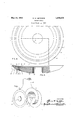
- FIG. 1 is a view of arotary drill embodying his invention
- Fig. 2 is a face view of a disk bit embodyng this invention
- Y Fig. 3 is a transverse section of the improved bit, taken on the line 33 of Fig. 2.
- a new and superior cutting tip may be applied thereto according to this invention by first machining of]? the worn periphery to form a hub portion H having inclined bevelled faces 11 and 12 which may meet in an intermediate edge or may be separated by a surface 13 as shown.
- the im- -3 proved renewable tip, which is separately formed, is then fusion welded to the outer periphery ofthe hub along the surfaces 11, 12 and 13.
- the hub portion of the disk may have a central opening 10 to receive a bearing pin or other means for rotatably mounting the same on'a suitable drill head or disk supporting body D.
- the improved tip comprises a ring R of steel, alloysteel or the like having inclined faces 14, 15 and 16 coextensive with its inner edge and cooperating with the bevelled faces 11 and 12 and the surface 13 to provide V-shape grooves to receive weld metal C, C such as steel or alloy steel, whereby the tip is welded to the steel hub H.
- the ring blank may at first be of rectangular cross-section, as
- dotted lines R desirably has an annular recess or channel L formed in one face to receive the lip L.
- the channel L may be inclined inwardly to pro. vide a deeper inner portion to receive a thicker section of the lip, the outer edge of the channel'and the lip therein being coextensive with.
- the lip L' is preferably applied by first welding a thin layer of the non-ferrous alloy onto the bottom of "the channel L' to tin this surface of the steel vents overheating and oxi rous metal will weld directly and more readily to the first non-ferrous metal coating and provide a working lip of pure non-ferrous alloy that is much more resistant to wear than steel, alloy steels and the like, and has the property of retaining its hardness and a sharp cutting edge under the most severe service conditions.
- the improved disk bit has an important advanta e over those heretofore used, in that it is sel -sharpening. As wear or abrasion occurs along the outer periphery of the bit, the steel ring R wears away faster than the harder non-ferrous metal lip L, thereby maintaining a sharpwear-resistant cutting edge of the non-ferrous metal at the outer periphery of the bit.
- the faces of the tip or combined ring and lip may be ground or machined to a shape matching the finished hub to form a bit having a dished front face and a convex rear face, for example.
- the inner edge of the ring is also finished with beveled surfaces to match those on the outer periphery of the hub to provide V-grooves to receive the weld metal that joins the tip to the hub.
- the ring thus carries the lip independently of the hub and away from the welded joint between the hub and ring, so that a worn tip may readily be removed from the hub by cutting along the welded joint with a gas flame.
- the improved tips are desirably manufactured in a factory or shop equipped with means to properly deposit the non-ferrous alloy onto the ring, "and to accurately machine'the tip. Such tips are then supplied to users in various sizes as replacement tips to be welded in the field onto properly machined hubs from which the worn tips have been cut.
- the improved disk bits may be rotatably mounted in the usual manner on horizontal pins P fixed in the legs D, D at the lower end of thehead D: rth3.t is rotatable about the vertical axis of the well.
- their lower ends may have deposits of the nonferrous alloy or similar wear-resistant metal welded thereto, as indicated at D, D".
- a ring-shaped tip adapted to be welded to the hub of a drill bit, such tip comprising a metal ring having a deposit of non-ferrous metal forming a lip on its working edge portion, said metal deposit being more resistant to wear than the body of sand. ring.
- a unitary separately-formed bit adapted for use in renewing the worn cutting edge of a tool having a supporting body of ferrous metal, said bit comprising a member of ferrous metal having both a working edge portion and a portion adapted to be welded to said supporting body; and a cutting lip coextensive with said working edge portion,
- said lip comprising non-ferrous metal welded to said working edge portion and being more resistant to wear than said member whereby the working edge portion of said coextensive with its working edge portion 7' and having a portion adapted to be welded to said supporting, body, and a cutting lip coextensive with said working edge portion, said lip comprising a deposit of non-ferrous metal in said channel and fused to the bottom and sides thereof, said deposit being more resistant to wear than said member w ereby the working edge portion of said ferrous metal body wears more rapidly than said lip and makes the bit self-sharpening.
Description
y 1932- I c. w. METZGER 1,859,978
ROTARY DR I LL Filed March 11, 1927 H FIG. 3.
IN VEN TOR.
Patented May 24, 1932 UNITED STATES PATENT OFFICE CLAUDE W. METZGER, OF LOS ANGELES, CALIFORNIA, ,ASSIGNOR '10 HAYNES STELLITE COMPANY, A CORPORATION or INDIANA I ROTARY Darn Application filed March 11, 1927. Serial N0. 174,544.
This invention relates to rotary. drills, and particularly to oil well and similar drills comprising one or more disk-shaped cutters or bits rotatably mounted in a substantlally upright position on a head that is rotatable about its longitudinal axis. More specifically, this invention relates to an improved separately manufactured bit in the form of a ring adapted to be welded to the per1phcry of a worm disk, as a replacement of virgin metal.
During the drilling operation, "the outer periphery of the usual disk drill bit wears away and soon becomes unserviceable because it fails to cut the hole to the required size, and as rapidly and economically as circumstances demand. It has been the practice to renew the worn portions of such bits by building up new edges thereon; for example, by fusion welding thereon metal from a steel welding rod until the bit is again of the required diameter and shape to function as a drilling tool. This procedure is objectionable because steel, alloy steels, or iron added by Welding in the manner described have not the cutting efliciency or wearing qualities of new steel hammered, rolled or otherwise Worked and properly heat treated.
The principal object of this invention is to provide improved means whereby such disk nits may be kept at high cutting efficiency. To this end, metal that is inherently of greatzr hardness and more wear-resistant than steel is applied to the working part of the )it which is subject to wear. The particular netal used for the cutting tip is a non-ferrous metal alloy, such as those described-in the )atents to Edward Haynes, Nos. 873,745, ,057,423, 1,057,828 and 1,150,113, which is referably applied to a separately formed :teel ring that is Welded onto the periphery f a worn disk bit.
The objects and novel features of this inention will became apparent from the folowing description taken with the accomanying drawings, in which Fig. 1 is a view of arotary drill embodying his invention;
Fig. 2 is a face view of a disk bit embodyng this invention; and Y Fig. 3 is a transverse section of the improved bit, taken on the line 33 of Fig. 2.
When the cutting edge of a steel disk has become worn, a new and superior cutting tip may be applied thereto according to this invention by first machining of]? the worn periphery to form a hub portion H having inclined bevelled faces 11 and 12 which may meet in an intermediate edge or may be separated by a surface 13 as shown. The im- -3 proved renewable tip, which is separately formed, is then fusion welded to the outer periphery ofthe hub along the surfaces 11, 12 and 13. As usual, the hub portion of the disk may have a central opening 10 to receive a bearing pin or other means for rotatably mounting the same on'a suitable drill head or disk supporting body D.
As shown, the improved tip comprises a ring R of steel, alloysteel or the like having inclined faces 14, 15 and 16 coextensive with its inner edge and cooperating with the bevelled faces 11 and 12 and the surface 13 to provide V-shape grooves to receive weld metal C, C such as steel or alloy steel, whereby the tip is welded to the steel hub H.
However, before the ring R is welded to the hub, and even before it is ground or otherwise formed to match the periphery of the hub, a lip L of wear-resistant metal is welded to its working edge. The ring blank may at first be of rectangular cross-section, as
roughly indicated by dotted lines R and desirably has an annular recess or channel L formed in one face to receive the lip L. The channel L may be inclined inwardly to pro. vide a deeper inner portion to receive a thicker section of the lip, the outer edge of the channel'and the lip therein being coextensive with.
the circular periphery of the forward corner of the ring.
' The metal forming the lip L is inherently,
of a higher degree of hardness and more wearresistant than the steel ring, and preferably consists of a non-ferrous metal alloy containing principally cobalt and one or more metals of the chromium group. The lip L'is preferably applied by first welding a thin layer of the non-ferrous alloy onto the bottom of "the channel L' to tin this surface of the steel vents overheating and oxi rous metal will weld directly and more readily to the first non-ferrous metal coating and provide a working lip of pure non-ferrous alloy that is much more resistant to wear than steel, alloy steels and the like, and has the property of retaining its hardness and a sharp cutting edge under the most severe service conditions. The improved disk bit has an important advanta e over those heretofore used, in that it is sel -sharpening. As wear or abrasion occurs along the outer periphery of the bit, the steel ring R wears away faster than the harder non-ferrous metal lip L, thereby maintaining a sharpwear-resistant cutting edge of the non-ferrous metal at the outer periphery of the bit.
After the wear-resistant lip L has been completely applied to the ring by fusion welding with an oxy-acetylene flame, electric arc, or the like, the faces of the tip or combined ring and lip may be ground or machined to a shape matching the finished hub to form a bit having a dished front face and a convex rear face, for example. The inner edge of the ring is also finished with beveled surfaces to match those on the outer periphery of the hub to provide V-grooves to receive the weld metal that joins the tip to the hub.
The ring thus carries the lip independently of the hub and away from the welded joint between the hub and ring, so that a worn tip may readily be removed from the hub by cutting along the welded joint with a gas flame. For convenience in renewing worn disk bits in the oil fields, the improved tips are desirably manufactured in a factory or shop equipped with means to properly deposit the non-ferrous alloy onto the ring, "and to accurately machine'the tip. Such tips are then supplied to users in various sizes as replacement tips to be welded in the field onto properly machined hubs from which the worn tips have been cut.
As shown in Fig. 1, the improved disk bits may be rotatably mounted in the usual manner on horizontal pins P fixed in the legs D, D at the lower end of thehead D: rth3.t is rotatable about the vertical axis of the well. In order to reduce wear of these legs, their lower ends may have deposits of the nonferrous alloy or similar wear-resistant metal welded thereto, as indicated at D, D".
With the improved bit, a given depth of hole can be drilled in considerably less time than formerly, the hole produced is more nearly straight in the direction desired and more satisfactory as to its gage or size, and
roundness. Furthermore, less power is required to rotate a drill carrying the improved self-sharpening bits, and since a sharper tool does not tend to move off the drilling axis as a blunt tool does, there is less'strain on the drill pipe, casing and other equipment used in drilling. vMoreover, the use of the imaspect, is not limited to the exact embodiment shown and described.
What is claimed is:
1. A ring-shaped tip adapted to be welded to the hub of a drill bit, such tip comprising a metal ring having a deposit of non-ferrous metal forming a lip on its working edge portion, said metal deposit being more resistant to wear than the body of sand. ring.
2. A ring-shaped tip com rising a metal ring beveled along its inner e ge whereby the same is adapted to be welded to the outer edge of a drill bit hub, an annular recess 1n 1ts front face, the outer edge of said recess being co-extensive with the outer edge of said ring and a deposit of metal in said recess forming. a lip, said metal deposit being more resistant to wear than said ring.
3. A unitary separately-formed bit adapted for use in renewing the worn cutting edge of a tool having a supporting body of ferrous metal, said bit comprising a member of ferrous metal having both a working edge portion and a portion adapted to be welded to said supporting body; and a cutting lip coextensive with said working edge portion,
said lip comprising non-ferrous metal welded to said working edge portion and being more resistant to wear than said member whereby the working edge portion of said coextensive with its working edge portion 7' and having a portion adapted to be welded to said supporting, body, and a cutting lip coextensive with said working edge portion, said lip comprising a deposit of non-ferrous metal in said channel and fused to the bottom and sides thereof, said deposit being more resistant to wear than said member w ereby the working edge portion of said ferrous metal body wears more rapidly than said lip and makes the bit self-sharpening.
In testimony whereof I affix my signature.
CLAUDE W. MLETZGER.
Priority Applications (1)
| Application Number | Priority Date | Filing Date | Title |
|---|---|---|---|
| US174544A US1859978A (en) | 1927-03-11 | 1927-03-11 | Rotary drill |
Applications Claiming Priority (1)
| Application Number | Priority Date | Filing Date | Title |
|---|---|---|---|
| US174544A US1859978A (en) | 1927-03-11 | 1927-03-11 | Rotary drill |
Publications (1)
| Publication Number | Publication Date |
|---|---|
| US1859978A true US1859978A (en) | 1932-05-24 |
Family
ID=22636549
Family Applications (1)
| Application Number | Title | Priority Date | Filing Date |
|---|---|---|---|
| US174544A Expired - Lifetime US1859978A (en) | 1927-03-11 | 1927-03-11 | Rotary drill |
Country Status (1)
| Country | Link |
|---|---|
| US (1) | US1859978A (en) |
Cited By (7)
| Publication number | Priority date | Publication date | Assignee | Title |
|---|---|---|---|---|
| US2575332A (en) * | 1946-06-19 | 1951-11-20 | Thomas H Coffey | Drill |
| US2693725A (en) * | 1947-03-03 | 1954-11-09 | Thomas H Coffey | Method of making metal cutting tools |
| US3081661A (en) * | 1957-11-08 | 1963-03-19 | Cowles Tool Company | Rotary shearing knife |
| US3326307A (en) * | 1965-01-28 | 1967-06-20 | Chicago Pneumatic Tool Co | Rock bit roller cone |
| US4506715A (en) * | 1983-05-11 | 1985-03-26 | Blackwell George T | Adzing bit assembly |
| US4706765A (en) * | 1986-08-11 | 1987-11-17 | Four E Inc. | Drill bit assembly |
| US20040000060A1 (en) * | 2002-07-01 | 2004-01-01 | Guangshan Zhu | Composite circular slicer knife |
-
1927
- 1927-03-11 US US174544A patent/US1859978A/en not_active Expired - Lifetime
Cited By (11)
| Publication number | Priority date | Publication date | Assignee | Title |
|---|---|---|---|---|
| US2575332A (en) * | 1946-06-19 | 1951-11-20 | Thomas H Coffey | Drill |
| US2693725A (en) * | 1947-03-03 | 1954-11-09 | Thomas H Coffey | Method of making metal cutting tools |
| US3081661A (en) * | 1957-11-08 | 1963-03-19 | Cowles Tool Company | Rotary shearing knife |
| US3326307A (en) * | 1965-01-28 | 1967-06-20 | Chicago Pneumatic Tool Co | Rock bit roller cone |
| US4506715A (en) * | 1983-05-11 | 1985-03-26 | Blackwell George T | Adzing bit assembly |
| US4706765A (en) * | 1986-08-11 | 1987-11-17 | Four E Inc. | Drill bit assembly |
| US20040000060A1 (en) * | 2002-07-01 | 2004-01-01 | Guangshan Zhu | Composite circular slicer knife |
| US20050211045A1 (en) * | 2002-07-01 | 2005-09-29 | Guangshan Zhu | Composite circular slicer knife |
| US7194933B2 (en) * | 2002-07-01 | 2007-03-27 | Premark Feg L.L.C. | Composite circular slicer knife |
| US20070137438A1 (en) * | 2002-07-01 | 2007-06-21 | Guangshan Zhu | Composite Circular Slicer Knife |
| US7257899B2 (en) | 2002-07-01 | 2007-08-21 | Premark Feg L.L.C. | Composite circular slicer knife |
Similar Documents
| Publication | Publication Date | Title |
|---|---|---|
| US6766870B2 (en) | Mechanically shaped hardfacing cutting/wear structures | |
| KR101037881B1 (en) | Rotary cutting bit with material-deflecting ledge | |
| US2318370A (en) | Oil well drilling bit | |
| US2640379A (en) | Drill | |
| US9701042B2 (en) | Method of making diamond mining core drill bit and reamer | |
| JPH04231164A (en) | Manufacture for bimetal castings and abrasive resistant parts produced by said method | |
| US1859978A (en) | Rotary drill | |
| US10711529B2 (en) | Cutting tool | |
| US2645471A (en) | Cutter bit | |
| WO2016061105A9 (en) | Protective wear sleeve for cutting element | |
| US2483220A (en) | Bit | |
| US10422186B2 (en) | Hardfacing metal parts | |
| US4258807A (en) | Method for making rock bits | |
| US2262212A (en) | Method of making composite tool joint members and the like | |
| CN107824818A (en) | A kind of volume cutting ring and its production technology for processing automobile key | |
| CN209761436U (en) | heavy-duty inserted cutter ring | |
| US1747394A (en) | Bearing for roller earth-boring drills | |
| US20170198577A1 (en) | Rotatable Cutting Tool | |
| US1860587A (en) | Cutter for rotary drills | |
| CA2970304C (en) | Earth-boring tools with precise cutter pocket location and orientation and related methods | |
| US2218069A (en) | Tool and method of making the same | |
| US2065898A (en) | Tool and method of making same | |
| US2310308A (en) | Alloy | |
| US1523912A (en) | Disk for rotary-drill bits | |
| US2329410A (en) | Process of welding manganese steels |