US1851565A - Process and apparatus for mining - Google Patents
Process and apparatus for mining Download PDFInfo
- Publication number
- US1851565A US1851565A US22912A US2291225A US1851565A US 1851565 A US1851565 A US 1851565A US 22912 A US22912 A US 22912A US 2291225 A US2291225 A US 2291225A US 1851565 A US1851565 A US 1851565A
- Authority
- US
- United States
- Prior art keywords
- tube
- oil
- nozzle
- mining
- well
- Prior art date
- Legal status (The legal status is an assumption and is not a legal conclusion. Google has not performed a legal analysis and makes no representation as to the accuracy of the status listed.)
- Expired - Lifetime
Links
- 238000005065 mining Methods 0.000 title description 46
- 238000000034 method Methods 0.000 title description 16
- 230000008569 process Effects 0.000 title description 5
- 239000000463 material Substances 0.000 description 45
- 239000003795 chemical substances by application Substances 0.000 description 43
- 239000004576 sand Substances 0.000 description 29
- 239000000203 mixture Substances 0.000 description 23
- 239000007788 liquid Substances 0.000 description 21
- 239000000470 constituent Substances 0.000 description 12
- CDBYLPFSWZWCQE-UHFFFAOYSA-L Sodium Carbonate Chemical compound [Na+].[Na+].[O-]C([O-])=O CDBYLPFSWZWCQE-UHFFFAOYSA-L 0.000 description 11
- 238000009825 accumulation Methods 0.000 description 7
- XLYOFNOQVPJJNP-UHFFFAOYSA-N water Substances O XLYOFNOQVPJJNP-UHFFFAOYSA-N 0.000 description 7
- 238000004891 communication Methods 0.000 description 6
- 230000006854 communication Effects 0.000 description 6
- NINIDFKCEFEMDL-UHFFFAOYSA-N Sulfur Chemical compound [S] NINIDFKCEFEMDL-UHFFFAOYSA-N 0.000 description 5
- 239000005864 Sulphur Substances 0.000 description 5
- 239000012530 fluid Substances 0.000 description 5
- 230000005484 gravity Effects 0.000 description 5
- 229910052500 inorganic mineral Inorganic materials 0.000 description 5
- 239000011707 mineral Substances 0.000 description 5
- 235000010755 mineral Nutrition 0.000 description 5
- 238000012856 packing Methods 0.000 description 5
- 238000000926 separation method Methods 0.000 description 5
- 229910000029 sodium carbonate Inorganic materials 0.000 description 5
- 235000017550 sodium carbonate Nutrition 0.000 description 5
- 230000009471 action Effects 0.000 description 4
- 230000007246 mechanism Effects 0.000 description 4
- 210000002445 nipple Anatomy 0.000 description 4
- 238000010521 absorption reaction Methods 0.000 description 2
- 239000010426 asphalt Substances 0.000 description 2
- 238000009412 basement excavation Methods 0.000 description 2
- 230000003028 elevating effect Effects 0.000 description 2
- 238000009413 insulation Methods 0.000 description 2
- 230000000750 progressive effect Effects 0.000 description 2
- 238000011084 recovery Methods 0.000 description 2
- BVKZGUZCCUSVTD-UHFFFAOYSA-L Carbonate Chemical compound [O-]C([O-])=O BVKZGUZCCUSVTD-UHFFFAOYSA-L 0.000 description 1
- 238000005054 agglomeration Methods 0.000 description 1
- 230000002776 aggregation Effects 0.000 description 1
- 230000008859 change Effects 0.000 description 1
- 230000006835 compression Effects 0.000 description 1
- 238000007906 compression Methods 0.000 description 1
- 230000001419 dependent effect Effects 0.000 description 1
- 230000000694 effects Effects 0.000 description 1
- -1 for instance Substances 0.000 description 1
- 239000012212 insulator Substances 0.000 description 1
- 239000003129 oil well Substances 0.000 description 1
- 230000001105 regulatory effect Effects 0.000 description 1
- 239000007787 solid Substances 0.000 description 1
Images


Classifications
-
- E—FIXED CONSTRUCTIONS
- E21—EARTH DRILLING; MINING
- E21B—EARTH DRILLING, e.g. DEEP DRILLING; OBTAINING OIL, GAS, WATER, SOLUBLE OR MELTABLE MATERIALS OR A SLURRY OF MINERALS FROM WELLS
- E21B43/00—Methods or apparatus for obtaining oil, gas, water, soluble or meltable materials or a slurry of minerals from wells
- E21B43/28—Dissolving minerals other than hydrocarbons, e.g. by an alkaline or acid leaching agent
Definitions
- This invention relates to the mining and treatment of minerals and particularly to the recovery of minerals which may be reduced to a uid state during the mining operation as described in Patent No. 1,607,586, the present application being a division thereof. 1
- the particular object of the invention resides in the recovery either from beneath or above the surface of the ground of minerals which canv be resolved into a ii'uid state during the mining operation 4and in the separation of the thus mined minerals from the inert material with which they are always associated.
- Fig. 1 is a sectional View of a portion of one formof the apparatus illustrating the giant, including tubings and the casing head.
- Fig. 2 vis a semi-diagrammatic view, partly in section, showing the apparatus which is associated with the parts illustrated in ig 1 and directly connected to the casing
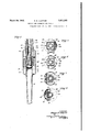
- Fig. 3 is an enlarged sectional view of a portion of the apparatus shown in Fig. 1, the casing and casing head being omitted,
- Fig. 4 is an enlarged sectional view of the nozzle and its associated parts
- Fig. 5 is a horizontal sectional view on line 5 5 of Fig. 3 looking in the direction of the arrows,
- Fig.l 6 is a similar view on line 6--6 of Fig. 3.
- Fig. 7 isa similar View on line 7-7 of Fig.- 3,
- Fig. 8 is similar view on line S-S of Fig. 3,
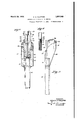
- Fig. 9 is an enlarged elevationalview partly broken away, of the nozzle shown in Fig. 4 andthe apparatus for operating the same,
- Fig. 10 is a detailed sectional View illustrating the elevating means for the nozzle and the means for retaining the elevating means in its inactive position
- u Fig. 11 is a side elevational view of the nozzle shown in Fig. 9, the View being taken at right angles to Fig. 9.
- the mechanism consists broadly of means for injecting a mining agent into the underground source of the oil, the elevation of the Huid oil, the separation of the oil from the mining agent and from the sand, andthe separation of the mining agent from the sand.
- the apparatus in the form illustrated, includes what I term a giant.
- This giant includes a tube 1 which is preferably, although not necessarily, quadrangular in cross section and which communicates with a tube 2 eX- tending through the casing 3 which is placed in the ground to line the well 4 and sealed therein by casing shoe 5.
- the tube 1 communicates with the tube 2 in the following manner:
- the adapter 6 is attached to the tube 2 by suitable means such as screw threads 7.
- This adapter carries at its lower end a sleeve f 8 which forms in effect an extension of the tube 1 and is attached to the adapter by means such as screw threads 9. Attached to the tube 1 at 10 is a packing ring 11 which in turn is adjustablv attached as at 12 to a second. packappear.
- the adapter 6 is provided with a series of ports 18 so designed that the pressure of the mining agent after passing therethrough will not exceed the desired working head for the nozzles 42, 29 and 31 when the tube 2 is iilled with the mining agent completely to ble pipe extending to a source of supply or' the mining agent.
- this source is two-fold, the agent being originally obtained from a tank 21 which is connected to the flexible pipe V20, by a relatively smaller pipe 22, the solution being raised through a pipe 23 and forced into the pipe 22, and consequently. into the pipe 2O by a steam injector 24 from which steam is injected froma suitable source, (not shown), through a' pipe 25, having a control valve 25 therein'.
- This tank 21 ' may be used as a mixing tank and the liquid, for instance, sodium carbonate, prepared within the tank in which case, water will be supplied to the tank through valve control pipe 21.
- the tank 21 may simply be used as a storage tank and the mining agent supplied to the tank through pipe 21', having been prepared elsewhere.
- the other source of supply of the mining agent is the heretofore referred to-separation tank 26 from which the agent, after having been separated from the oil and the sand, is conducted to the pipe 20 through a pipe 27 having a bark plate 27 spaced from the end thereof.
- nozzles 28 and 29 adjacent the lower end of the tube 1, the former extending outwardly from the tube and the latter, located below the former, extending downwardly.
- These nozzles are adapted to be closed by suitable closures 30 and 31, closure 30 of the nozzle 28 having a central opening 30 therein for a purpose which will later appear.
- the nozzle 28 (see Fig. 6) is offset or tangential with respect to the longitudinal axis of the tube 1 so that when the mining agent is projected from the-nozzle the tube will be given a rotative movement by the reactive torce of the agent leaving the nozzle, so that the agent will be automatically projected against the wall of the well in a progressive circle.
- the lower end of the tube 1 is closed and guided on anti-friction bearings in the following manner: Secured to the tube 1 at 32 is a packing ring 33 which its within the tubeY 1 and is, at its upper end, of a cross section similar to that of the tube. At its lower end, however, it is of a circular cross section so as to snugly fit the tube 34 which is likewise circular in cross section and extends upwardly through the tube 1.- A second ring 35 is attached adjustably at 36 to the ring 33 and disposed between these packing rings is suitable 35, anti-friction bearings 41 are disposed.
- the tube 1 is supported at its upper and at its lower ends by antifriction bearings and is packed so as to pre-
- This tube 1 is provided with a relatively larger nozzle 42.
- This nozzle 42 is provided with a head 43 which head is mounted for pivotal movement at v44 on a bracket v45 carried by the tube 1.
- the head 43 is formed of twochambers, 46 and 47 These chambers 46 and'47 are disposed upon the opposite sides of the tube 1 andare attached at 50 to the nozzle l42 having permanent communication with the same 51.
- a lifting rod 54 which is attached pivotally- 'to the chambers 46 and 47 by means of a yoke 55 and is y normallv urged upwardly by a spring 56 mounted within a housing ,57 and disposeds between an abutment 58 on the end of the rod 54 and a permanent abutment 59 on the lower end of the housing.
- the spring 56 is, when desired, maintained under compression and in an inoperative position, that is to say, in- ⁇ operative to'raise the nozzle 42, by a removable Din 60 which .extends through the housing 57 and in the form illustrated 'is shown as in screw threaded attachment therewith at" 61.
- sto s 63 (SI1 and in dotted lines in ig. 3) which stops are disposed on opposite sides of the tube 1 and adapted to engage the upper surfaces of wings 64 which project from the chambers 46 i and 47 of the head 43 of the nozzle 42 and the ground, I have mounted a tube 65 ⁇ in the own in Fig. 1l
- eisernes I adapter 6 which tube and its upper end communicates with tube 66 having a reducing nipple 67 at its lower end above the end of the tube 65, for a purpose which will later appear, and which tube 66 is, at its upper end, provided with a tubing head 68 having connection to a flexible pipe 69 which in turn is connected to a heat exchanger 70 having a jacket 71 for the circulation of water to the boiler and having communication with the tank 26 through its open end 72.
- A. baille plate 72 is placed from this open end 72 of the pipe 70.
- the tube 65 extends downwardly to a point beyond the lower end of the tube 1 and to the extent desired and is provided at its lower end with a steam injector 7 3 including a Venturi tube 74 and a nozzle 75 which latter extends into the Venturi tube and is relatively smaller than the same to provide the steam space 76 and is carried at 77 by a housing 78 which is attached Vat its upper end to the lower end of the tube 341.
- rl ⁇ hishousing 78 carries the Venturi tube 74, the latter being mounted therein by means of suitable vanes 79 in the usual manner.
- the lower end of the housing 78 is provided with a chamber 80 having perforations 81 therein, which chamber is closed by a cap 82 at its lower end and through which perforation the material to be raised passes to the nozzle 75.
- the tube 34 is provided which tube has a slightly greater diameter than the tube 66 and provides the steam space 83 therebetween.
- This tube 34 is carried by the adapter 6 being attached thereto at 84 and having communication with a series of steam ports 85 in the adapter which ports establish communican tion with the steam space 86 between the tube 2 and an outer tube 87 which is attached at 88 to the adapter and at its upper end is provided with a tubing head 89 having a steam inlet 90 from vany suitable source (not shown).
- the tube 2 is provided with'heat insulation 91 to prevent the com munication of heat from ythe steam passing through the steam space 86 between the tubes 2 and 87 to the mining agent passing through the tube 2. This is most clearly shown in Fig.
- a pump of the type usually usedin tht ⁇ oil wells, and a rod 95 is mounted to operate within the tube 66 for a purpose which will later appear.
- the tank or con tainer 26 is mounted above the ground and is adaptedto separate the oil from the mining agent and the solid or inert material, and the mining agent from the inert material.
- This container has, in addition to the pipe 27 for taking oit the mining agent yand the pipe 72 for conveying the mixture of the mined material and mining agent to the container, a pipe 96 which extends from the upper end of the container and ris provided with a pressure regulating valve 97.
- This pipe 96 is adapted to carry 0H the oil preferably to a heat exchanger whichwill reduce the oil to a convenient temperature for handling.
- the water thus entering is slightly in excess ot the pressure within the container 26.
- sodium carbonate is disclosed in this application the invention is'not limited to its use, for it is contemplated that other materials which are capable of breaking down the surface tension between the two materials, such for instance as other alkaline liquids having this property, may be employed.
- the mining agent which for the purpose of illustration has been designated as a solution of water and carbonate of soda, is forced down through the tubing head 19 from the pipe 20 and the source to whichthe latter is' connected, that is to say, the tanks 21 and 26, into the tube 1 from whence it escapes under pressure so as to be flexibly projected against the wall of the well from the nozzle 28.
- the solution escapes downwardly from the casing 1 to the nozzle 29, it being ejected under considerable pressure.
- the nozzle 28 with the wall of the/well, will excavate the oil bearing sand from the productive strata 105, which sand will drop to the bottom of the well, the excavated sand at the bottom of the well being continuously agitated by the solution which is ejected from the nozzle 29.
- the range' of the nozzle 28 is such that it will excavate the -oilrbearing sand from the productive strata to an extent sufficient to produce an opening of a radius greater than the length of the nozzle 42. lit is here pointed out that the container 26 before the operation is started is, like the container 21, filled with the mining agent so that the supply even at the beginning of the operation may come from both sources.
- the reactive force developed by the escape of the mining agent from the reduced oriiice of the nozzle 28 causes the rotation of the tube l which carries the nozzle 42 so that the latter excavates the oil bearing sand from the productive strata in a progressive circle and from the bottom toward the top of the strata, the giant being gradually raised as the excavation takes place.
- the nozzle 29 serves to agitate the oil and sand accumulated at the vbottom of the joint so that the mixture may .be raised initially to yfree the well from a portion'of sand'which is brought down from the wail.
- the cap 82 on the lower end of the housing 78 will be raised a short distance above the 'surface of the sand. This may be accomplished by the operators lowering the apparatus until the cap rests upon the sand and subsequently raising the sameto the desired extent. This will insure the elevation of the liquid without sand or inert material. As the excavated sand and oil ows into the lower part of the well the sand of course seeks an angle of repose sloping towards the center of the well and the liquid accumulates above the same.
- the in :lector 7 3 raises the liquid through the tube 65 into' the tube 66 to an extent dependent upon the pressure of the steam. This forms a working head for the nozzle 42 and the liquid. ⁇ ilows past the bottom of the raised tube 66 and then through the ports 18 back to the nozzles.
- the steam is shut ott and the tube 66 is lowered and screwed into its seat in the. adapter 6 and the giant is raised slightly so that the apertured end of. the housing 78 extends into the accumulation of oil in the poolv and the steam turned on through the pipeQQO.
- This steam, operating the injector 7 3 raises the oil through the tube into the tube 66 and the oil thus raised is drawn from the tube 66 by the auxiliary raising means which in the case illustrated in the drawings is a plun er pump.
- the sand, oil and mixing agent are being raised, they are together discharged into the container 26 through the heat exchanger and the open end 72 of thepipe 70.
- the greatly reduced velocity which is the result oi the discharge of the material into the greatly enlarged container 26, facilitates the arrangement of the sand, mining agent and oil, according to their speciiic -gravities, the sand falling to the bottom and being removed by the Spitzkasten, the mining agent arranging itself above the sand and' the oil above the mining agent.
- the mining agent when it reaches the injector 7 3 must be at a comparatively low temperature in order to have the injector properly operate and for this reason the agent, which is forced through the pipe 20, is kept at theldesirable temperature. when the mining agent is conveyed to the container 26 through the tubes 69 and 70, it is at.
- the invention is admirably applicable to the mining of sulphur and in .tact other minerals which will assume a iiuid state.
- the apparatus illustrated in the drawings may be used, but the method will dier to some extent in that instead of the particular mining agent which is adapted to resolve the oil into the duid state, a mining agent which is particularly adapted to put the sulphur into a fluid state is used.
- T contemplate the use of steam preferably superheated., ⁇ to act upon the ,sul hur deposit to resolve it into a fluid state; instead of depending upon steam to operate the injector T depend upon compressed air, preferably in a heated state, to raise the melted sulphur to the surface.
- the separation tank 26 and other apparatus at the casing head is dispensed with, as well as the pipe insulation 91. Otherwise, the operavmined, except that after an opening of sutlicient size to accommodate the nozzle 42. has beenreamed, the automatic rotary movement of the giant is stopped. This may be accomplished by tightening the packing rings 15 and 39A so that the tube 1 is locked to the stationary tube 34.
- the operator may change the direction of the large nozzle 42 occasionallly as desired by turning the tubing slightly at the casing head. At this time the nozzle 28 may be closed. Nozzle 29 will remain open to maintain the sulphur accumulation at the bottom of the giant in a fluid state for raising.
- What l claim is z 1.
- the method ot recovering oil from under ground strata in a Well which includes rojecting a stream of liquid capable of reaking down the surface tension between the oil and the inert materials to :tree the oil from the inert material against the oil bearing strata in the Well, accumulating said oil and inert material in the Well, constantly agitating the same by directing a stream of said liquid under pressure into the accumulation, lifting a portion ot all oi the constituents of the accumulated mixture above the ground and separating the constituents of the mixture, thereafter permitting the remainder ot the accumulated materials to separate in the well by gravity, and lit'ting the oil iromsaid accumulation.
Description
PROCSS AND APPARATUS FOR MINING Original- Filed Oct. l, 1924 5 Sheets-Sheet l INVENTOR March 29, 1932. E. E. cLAYToR '1,851,565
PROCESS AND APPARATUS FOR MINING Original Filed Oct. l, 1924 5 Sheets-Sheet 2 INVENTOR March 29, 1932. E. E. CLAYTOR 1,851,555
PROCESS AND APPARATUS FOR MINING Original Filed Oct. l, 1924 5 Sheets-Sheet 5 INVENTOR- idw/'1f Y 'Zagidl ATT March 29, 1932. E. E. cLAYToR PROCESS AND APPARATUS FOR MINING original Filed oct. 1, 19214 5 Sheets-Sheet 4 l l o,
' INVENTCR- Edwin 1' 'iaylal.
March 29, 1932. E. E. cLAYToR 1,851,565
PROCESSV AND APPARATUS FO MINING Original Filed Oct. l, 1924 5 Sheets-Sheet 5 .i5 h, Il. 43 l` 47 1221 IIL-"Il 50 l 1 INVENTQR- Edwin 'laylzz Patented Mar.` 2,9, 1932 PATENT OFFICE EDWIN E. CLAYTOR, OF'NEW YORK, Y., ASSIGNOR T0 CHARLES PAUL MACKIE, 0I'
NEWARK, NEW JERSEY PROCESS AND APPARATUS FOR MINING Original application lled October 1, 1924, Serial No. 740,911. Divided and this application iled April 13, A 1925. Serial No. 22,912.
This invention relates to the mining and treatment of minerals and particularly to the recovery of minerals which may be reduced to a uid state during the mining operation as described in Patent No. 1,607,586, the present application being a division thereof. 1
The particular object of the invention resides in the recovery either from beneath or above the surface of the ground of minerals which canv be resolved into a ii'uid state during the mining operation 4and in the separation of the thus mined minerals from the inert material with which they are always associated.
In describing the invention I will first show its application to the mining of bituminous materials such as oil bearing sands from beneath the ground, but it is to be understood that the invention is not limited to this particular application as it will later appear.
In the drawings, which illustrate a mechanism for carrying out the method of mining the oil bearing sand,
Fig. 1 is a sectional View of a portion of one formof the apparatus illustrating the giant, including tubings and the casing head.
Fig. 2 vis a semi-diagrammatic view, partly in section, showing the apparatus which is associated with the parts illustrated in ig 1 and directly connected to the casing Fig. 3 is an enlarged sectional view of a portion of the apparatus shown in Fig. 1, the casing and casing head being omitted,
Fig. 4 is an enlarged sectional view of the nozzle and its associated parts,
Fig. 5 is a horizontal sectional view on line 5 5 of Fig. 3 looking in the direction of the arrows,
Fig. 7 isa similar View on line 7-7 of Fig.- 3,
Fig. 8 is similar view on line S-S of Fig. 3,
Fig. 9 is an enlarged elevationalview partly broken away, of the nozzle shown in Fig. 4 andthe apparatus for operating the same,
Fig. 10 is a detailed sectional View illustrating the elevating means for the nozzle and the means for retaining the elevating means in its inactive position, and u Fig. 11 is a side elevational view of the nozzle shown in Fig. 9, the View being taken at right angles to Fig. 9.
The mechanism consists broadly of means for injecting a mining agent into the underground source of the oil, the elevation of the Huid oil, the separation of the oil from the mining agent and from the sand, andthe separation of the mining agent from the sand.
The apparatus, in the form illustrated, includes what I term a giant. This giant includes a tube 1 which is preferably, although not necessarily, quadrangular in cross section and which communicates with a tube 2 eX- tending through the casing 3 which is placed in the ground to line the well 4 and sealed therein by casing shoe 5. The tube 1 communicates with the tube 2 in the following manner:
The adapter 6 is attached to the tube 2 by suitable means such as screw threads 7.
This adapter carries at its lower end a sleeve f 8 which forms in effect an extension of the tube 1 and is attached to the adapter by means such as screw threads 9. Attached to the tube 1 at 10 is a packing ring 11 which in turn is adjustablv attached as at 12 to a second. packappear.
The adapter 6 is provided with a series of ports 18 so designed that the pressure of the mining agent after passing therethrough will not exceed the desired working head for the nozzles 42, 29 and 31 when the tube 2 is iilled with the mining agent completely to ble pipe extending to a source of supply or' the mining agent. I have illustrated this source as being two-fold, the agent being originally obtained from a tank 21 which is connected to the flexible pipe V20, by a relatively smaller pipe 22, the solution being raised through a pipe 23 and forced into the pipe 22, and consequently. into the pipe 2O by a steam injector 24 from which steam is injected froma suitable source, (not shown), through a' pipe 25, having a control valve 25 therein'. This tank 21 'may be used as a mixing tank and the liquid, for instance, sodium carbonate, prepared within the tank in which case, water will be supplied to the tank through valve control pipe 21. However, it is to be understood that the tank 21 may simply be used as a storage tank and the mining agent supplied to the tank through pipe 21', having been prepared elsewhere.
, The other source of supply of the mining agent is the heretofore referred to-separation tank 26 from which the agent, after having been separated from the oil and the sand, is conducted to the pipe 20 through a pipe 27 having a baie plate 27 spaced from the end thereof.
In order that the mining agent may be projected against the walls of the well I have located nozzles 28 and 29 adjacent the lower end of the tube 1, the former extending outwardly from the tube and the latter, located below the former, extending downwardly. These nozzles are adapted to be closed by suitable closures 30 and 31, closure 30 of the nozzle 28 having a central opening 30 therein for a purpose which will later appear. The nozzle 28 (see Fig. 6) is offset or tangential with respect to the longitudinal axis of the tube 1 so that when the mining agent is projected from the-nozzle the tube will be given a rotative movement by the reactive torce of the agent leaving the nozzle, so that the agent will be automatically projected against the wall of the well in a progressive circle.
The lower end of the tube 1 is closed and guided on anti-friction bearings in the following manner: Secured to the tube 1 at 32 is a packing ring 33 which its within the tubeY 1 and is, at its upper end, of a cross section similar to that of the tube. At its lower end, however, it is of a circular cross section so as to snugly fit the tube 34 which is likewise circular in cross section and extends upwardly through the tube 1.- A second ring 35 is attached adjustably at 36 to the ring 33 and disposed between these packing rings is suitable 35, anti-friction bearings 41 are disposed.
Thus it will be seen that the tube 1 is supported at its upper and at its lower ends by antifriction bearings and is packed so as to pre- This tube 1 is provided with a relatively larger nozzle 42. This nozzle 42 isprovided with a head 43 which head is mounted for pivotal movement at v44 on a bracket v45 carried by the tube 1.
Referring particularly to Figures 4 to8 invent the escape of the mining agent except -through the ejectionI nozzles. `75
clusive,.it will be seen that the head 43 is formed of twochambers, 46 and 47 These chambers 46 and'47 are disposed upon the opposite sides of the tube 1 andare attached at 50 to the nozzle l42 having permanent communication with the same 51.
through openings i In order that communication may be estabi lished between the chambers 46 and 47 of the nozzle when the latter is in its raised position, such as shown in Fig. 1, I have provided each-of the chambers with openings 52 which openings areadapted to register with openings 53 in the tube 1 (see Fig. 5). L
In order that the nozzle 42 maybe auto-` matically raised into its operative, position as shown in Fig. 1, I have provided a lifting rod 54 which is attached pivotally- 'to the chambers 46 and 47 by means of a yoke 55 and is y normallv urged upwardly by a spring 56 mounted within a housing ,57 and disposeds between an abutment 58 on the end of the rod 54 and a permanent abutment 59 on the lower end of the housing. The spring 56 is, when desired, maintained under compression and in an inoperative position, that is to say, in-` operative to'raise the nozzle 42, by a removable Din 60 which .extends through the housing 57 and in the form illustrated 'is shown as in screw threaded attachment therewith at" 61. This hus'ing 57 lis carried by the packing ring 11- as at 62.-
In order that the nozzle'42 may be limited in its upward movement under the action of the spring 56 so as to be arrested in the proper position to project the minin agent, I have provided a pair of sto s 63 (SI1 and in dotted lines in ig. 3) which stops are disposed on opposite sides of the tube 1 and adapted to engage the upper surfaces of wings 64 which project from the chambers 46 i and 47 of the head 43 of the nozzle 42 and the ground, I have mounted a tube 65\in the own in Fig. 1l
eisernes I adapter 6, which tube and its upper end communicates with tube 66 having a reducing nipple 67 at its lower end above the end of the tube 65, for a purpose which will later appear, and which tube 66 is, at its upper end, provided with a tubing head 68 having connection to a flexible pipe 69 which in turn is connected to a heat exchanger 70 having a jacket 71 for the circulation of water to the boiler and having communication with the tank 26 through its open end 72. A. baille plate 72 is placed from this open end 72 of the pipe 70. j
The tube 65 extends downwardly to a point beyond the lower end of the tube 1 and to the extent desired and is provided at its lower end with a steam injector 7 3 including a Venturi tube 74 and a nozzle 75 which latter extends into the Venturi tube and is relatively smaller than the same to provide the steam space 76 and is carried at 77 by a housing 78 which is attached Vat its upper end to the lower end of the tube 341. rl`hishousing 78 carries the Venturi tube 74, the latter being mounted therein by means of suitable vanes 79 in the usual manner. ,The lower end of the housing 78 is provided with a chamber 80 having perforations 81 therein, which chamber is closed by a cap 82 at its lower end and through which perforation the material to be raised passes to the nozzle 75. j
ln order that the steam may be supplied to the injector, the tube 34: is provided which tube has a slightly greater diameter than the tube 66 and provides the steam space 83 therebetween. This tube 34, as hereinbefore stated, is carried by the adapter 6 being attached thereto at 84 and having communication with a series of steam ports 85 in the adapter which ports establish communican tion with the steam space 86 between the tube 2 and an outer tube 87 which is attached at 88 to the adapter and at its upper end is provided with a tubing head 89 having a steam inlet 90 from vany suitable source (not shown).
llt will be noted that the tube 2 is provided with'heat insulation 91 to prevent the com munication of heat from ythe steam passing through the steam space 86 between the tubes 2 and 87 to the mining agent passing through the tube 2. This is most clearly shown in Fig.
lt has hereinbefore been Vstated that the agenrwhen in the form of an alkaline liquid such as soda ash and water, is obtained from the tank 21 in a heated condition. This' liquid may be heated by the steam which supplies the injector 24 by simply opening a valve 92 which is located in a 'pipe 93 having communication withthe steam supply pipe 25 and extending into the tank 2l.
A pump, of the type usually usedin tht` oil wells, and a rod 95 is mounted to operate within the tube 66 for a purpose which will later appear.
As hereinbefore stated, the tank or con tainer 26 is mounted above the ground and is adaptedto separate the oil from the mining agent and the solid or inert material, and the mining agent from the inert material. This container has, in addition to the pipe 27 for taking oit the mining agent yand the pipe 72 for conveying the mixture of the mined material and mining agent to the container, a pipe 96 which extends from the upper end of the container and ris provided with a pressure regulating valve 97. This pipe 96 is adapted to carry 0H the oil preferably to a heat exchanger whichwill reduce the oil to a convenient temperature for handling.
ln order that the inert material may be continuouslycarried od from the container 26, l have provided the same with a Spitzkasten separator which includes the tapered lower end 98 ofthe container 26-which is connected by a pipe 99 to the T 100, from which latter nipples 101 and 102 extend. 'llhese nipples `are connected to valves 103 and 101. Water, preferably cold, is admitted through the valve 103 into the nipple 101 and some of this water will pass out through the valve 104; when the later is open, while the remaining part will pass upwardly through the pipe 99 into the container 26.
The water thus entering, is slightly in excess ot the pressure within the container 26.
This slow entering of the waterprevents the in the instance disclosed is sodium carbonate,
is to free the material which is capable of assuming a liquid state from the material which is incapable of assuming such a state, and this is accomplished by the breaking down of the surface tension between the two materials, or where oil is being recovered from' sand by the breaking down of the surface tension between the sand and the oil. rlhis breaking down of the surfacetension is accomplished by projecting the mining agent against the agglomeration of the two materials and results in the releasing of all of the oil from the inert'material of the sand.
While sodium carbonate is disclosed in this application the invention is'not limited to its use, for it is contemplated that other materials which are capable of breaking down the surface tension between the two materials, such for instance as other alkaline liquids having this property, may be employed.
I In operation, when oil or bitumen are being mined, and after the well casing andshoe have been put in place, the giant and' tubes to y*which it is attached are lowered into the well, the nozzle 42 at this time lying the position shown in Figure 3 of the drawings,
lthat is to say, substantially parallel with the within the-well, with the nozzle 28 adjacent Vi the top or bottom ofthe productive strata 105, the closures 30 and 31 of the nozzles- 28 and 29 having been previously removed, the mining agent, which for the purpose of illustration has been designated as a solution of water and carbonate of soda, is forced down through the tubing head 19 from the pipe 20 and the source to whichthe latter is' connected, that is to say, the tanks 21 and 26, into the tube 1 from whence it escapes under pressure so as to be flexibly projected against the wall of the well from the nozzle 28. At the same time part of the solution escapes downwardly from the casing 1 to the nozzle 29, it being ejected under considerable pressure. The impact of the solution passing from the nozzle,
28 with the wall of the/well, will excavate the oil bearing sand from the productive strata 105, which sand will drop to the bottom of the well, the excavated sand at the bottom of the well being continuously agitated by the solution which is ejected from the nozzle 29. The range' of the nozzle 28 is such that it will excavate the -oilrbearing sand from the productive strata to an extent sufficient to produce an opening of a radius greater than the length of the nozzle 42. lit is here pointed out that the container 26 before the operation is started is, like the container 21, filled with the mining agent so that the supply even at the beginning of the operation may come from both sources. As the oil bearing sand is excavated the tubing and giant are lowered the housing 78 through which it passes bctween the vanes 79, the steam passing through the space 76, into theVenturi tube 74. The action of this injector -draws the material, which includes the mining agent, the sand and oil, through the openings or perforations 81, and raises it through the tube and thence into the tube 66. This material ascends within the tube 66 because of the steam pressure which urges it upwardly. Inasmuch 'as it is impracticable to inject steam under sufficient pressur to raise the material completely from the well, except in comparatively shallow wells, the raising action of the steam can be supplemented by auxiliary means such, for
instance, as a plunger pump, air lift, swabbing, or baling, or the like, the particular method shown being a plunger pump. Thus by the combined action of the steam and the auxiliary lifting means, the liquid and material is lifted from the well.
After the oil bearing stratahas been re- I recess created by the previous excavation it automatically moves into its operative positionas shown in Figure 1. Having assumed this position the mining agent is again forced into the tube 1 and the steam into the injector through pipes as hereinbefore stated. The major portion of the mining agent escapes from the nozzle 42 while a considerably smaller portion escapes through nozzle' 29 and the reduced orifice of the nozzle 28 which is adected by the presence of the closure 30 having the smaller opening 30 therein. \At this time, that isto say, when the operation of the nozzle 42 begins, the nozzle is located so that it projects the mining agent against the wall of the previously formed cavity ado jacent the bottom of the oil bearing strata.
The reactive force developed by the escape of the mining agent from the reduced oriiice of the nozzle 28 causes the rotation of the tube l which carries the nozzle 42 so that the latter excavates the oil bearing sand from the productive strata in a progressive circle and from the bottom toward the top of the strata, the giant being gradually raised as the excavation takes place. The nozzle 29 serves to agitate the oil and sand accumulated at the vbottom of the joint so that the mixture may .be raised initially to yfree the well from a portion'of sand'which is brought down from the wail.
The excavated material is removed from 'the well as in the previous operation of recessing with the small nozzle 28, and excava- Anozzle 42, and the tube 66- is unscrewed from its seat in the adapter 6 and is raised a short distance and maintained in this position, and
line.
meanest then the apparatus is again lowered into the well.
lt is-pointed out that when the apparatus is lowered into the well andthe nozzle 42 assumes its operative position, the cap 82 on the lower end of the housing 78 will be raised a short distance above the 'surface of the sand. This may be accomplished by the operators lowering the apparatus until the cap rests upon the sand and subsequently raising the sameto the desired extent. This will insure the elevation of the liquid without sand or inert material. As the excavated sand and oil ows into the lower part of the well the sand of course seeks an angle of repose sloping towards the center of the well and the liquid accumulates above the same. The in :lector 7 3 raises the liquid through the tube 65 into' the tube 66 to an extent dependent upon the pressure of the steam. This forms a working head for the nozzle 42 and the liquid.` ilows past the bottom of the raised tube 66 and then through the ports 18 back to the nozzles. When, however, a sufficient amount of oil has accumulated on the surface of the pool and above the mining agent and sand, which are separated from the oil by gravity, the steam is shut ott and the tube 66 is lowered and screwed into its seat in the. adapter 6 and the giant is raised slightly so that the apertured end of. the housing 78 extends into the accumulation of oil in the poolv and the steam turned on through the pipeQQO. This steam, operating the injector 7 3, raises the oil through the tube into the tube 66 and the oil thus raised is drawn from the tube 66 by the auxiliary raising means which in the case illustrated in the drawings is a plun er pump. wt
en during the initial portion ot the operation otthe apparatus, that is to say when the sand, oil and mixing agent are being raised, they are together discharged into the container 26 through the heat exchanger and the open end 72 of thepipe 70. The greatly reduced velocity which is the result oi the discharge of the material into the greatly enlarged container 26, facilitates the arrangement of the sand, mining agent and oil, according to their speciiic -gravities, the sand falling to the bottom and being removed by the Spitzkasten, the mining agent arranging itself above the sand and' the oil above the mining agent.
Then again when the oil alone is being raised it need not be discharged into the con-4 tainer 26, but may be by-passed to the pipe if, however, it is discharged into the container 26 it, and the mining agent, will arrange themselves according to their' specific gravities so that'oil may be drawn od from the top of the container throu h the pipe 96, the pressure reducing valve 26 in the pipe 27 being closed.
It will be seen that by this method of operation the major portion of the oil contained in the productive strata and oil bearing sand is separated from the sand within the welland is raised from the well free of the mining agent and of the sand. l
It is of course to be understood that the mining agent when it reaches the injector 7 3 must be at a comparatively low temperature in order to have the injector properly operate and for this reason the agent, which is forced through the pipe 20, is kept at theldesirable temperature. when the mining agent is conveyed to the container 26 through the tubes 69 and 70, it is at.
a greatly elevated temperature owing to the absorption of heat from the steam in its passage in the tubes 65 and 66. This temperature lis so high that should it again be circulated heat insulator 91 which has been hereinbefore It is of course realized that` described, is desirable so as to prevent the absorption of heat from thesteam in the space 86 by the mining agent in its movement downwardly through the tube 2.
lin the above description l have given as an example the mining of oil from beneath the ground, but it is to be understood, as hereinbefore stated, that the invention is equally applicable to the mining of oil and bitumen from outcrops or surface deposists in which case of course the giant and the mechanism which adapts the apparatus for use beneath the ground may be omitted and the mining agent projected froma suitable mechanism connected with the supply so as to free the material which can assume a fluid state from the inert material which cannot assume such a state.
Furthermore, the invention is admirably applicable to the mining of sulphur and in .tact other minerals which will assume a iiuid state. When sulphur is mined, for instance, from beneath the ground, the apparatus illustrated in the drawings may be used, but the method will dier to some extent in that instead of the particular mining agent which is adapted to resolve the oil into the duid state, a mining agent which is particularly adapted to put the sulphur into a fluid state is used. In this instance T contemplate the use of steam preferably superheated., `to act upon the ,sul hur deposit to resolve it into a fluid state; instead of depending upon steam to operate the injector T depend upon compressed air, preferably in a heated state, to raise the melted sulphur to the surface. The separation tank 26 and other apparatus at the casing head is dispensed with, as well as the pipe insulation 91. Otherwise, the operavmined, except that after an opening of sutlicient size to accommodate the nozzle 42. has beenreamed, the automatic rotary movement of the giant is stopped. This may be accomplished by tightening the packing rings 15 and 39A so that the tube 1 is locked to the stationary tube 34. The operator may change the direction of the large nozzle 42 occasionallly as desired by turning the tubing slightly at the casing head. At this time the nozzle 28 may be closed. Nozzle 29 will remain open to maintain the sulphur accumulation at the bottom of the giant in a fluid state for raising.
It will be seen from the foregoing description that I have provided a method and an apparatus for freeing material which is ca'- pable of assuming a fluid state from'material which is incapable of assuming such a state and for raisingthe 'luid material from the ground to the surface when such material is mined from beneath the surface of the ground.
What l claim is z 1. The method ot recovering oil from under ground strata in a Well which includes rojecting a stream of liquid capable of reaking down the surface tension between the oil and the inert materials to :tree the oil from the inert material against the oil bearing strata in the Well, accumulating said oil and inert material in the Well, constantly agitating the same by directing a stream of said liquid under pressure into the accumulation, lifting a portion ot all oi the constituents of the accumulated mixture above the ground and separating the constituents of the mixture, thereafter permitting the remainder ot the accumulated materials to separate in the well by gravity, and lit'ting the oil iromsaid accumulation.
2. The method otrecoveringoil'fromunder ground strata in a vvell, which includes projecting a stream of liquid capable oi freeing the oil from the inert material under pressure,
' againstthe oil/,bearing strata in the Well, acu
Vcumulating said oil and inert material in the Well, constantly agitating the same by directing a stream of said liquid under` pressure into the accumulation, lifting a portion of all of the constituents of the accumulated mixture above the ground and separating the constituents "of the mixture by gravity.
3. The method of recovering the oil from the underground strata in a well which includes projecting a Warm alkaline liquid capable of breaking down thesurfacetensionbetween said materials against the strata under pressure to separate the oil and inert material from the strata and the oil from the inert material, permitting the mixture to accumulate in the Well, constantly agitating -said mixture by injecting a stream of said liquid into the same, lifting a portion of all of the constituents of said mixture by the pressure-l the underground strata in a Well which lincludes projecting a Warm solution of sodium carbonate against the strata in the well under ressure to separate the oiland inert material rom the strata and 'the oil from the inert material, permitting the mixture to accumulate in the well, constantly agitating said mixture by injecting a stream of said liquid into the same, lifting a portion of all of the constituents of said mixture by the pressure-A lift princi le, thereafter permitting the constituents el) the remainder of the accumulated mixture to arrange themselves i-n the Well according to their specific gravities, and litt'-a ing the oil trom said mixture.l
Stvl
5. rll`he method of recovering the oil from the under ground strata in a Well which includes projecting a Warm alkaline liquid against thestrata in the Well 'under pressure to separate the oil and inert: material from the strata and the oil from the"\inert material by breaking dovvn the surface tension between said materials, permitting the mixture to accumulatein the Well, constantly agitating the said mixture by injecting a stream ot said liquid into the same, and lifting a portion ot all oi the constituents of said mixture by the pressurelilt principle.
6.. 'lhe method of recovering oil trom un derground strata in a" Well which includes projecting a stream ot liquid capable or treeing the oil from the inert material against the oil bearing strata, accumulating said oil and said inert material in the Well, agitating the accumulation, and lifting a portion of all or the constituents ot the accumulated mixture above the ground and separating the constituents of said mixture.
7. The method of recovering oil trom un! dergroun'd strata "in a Well 'which incudes projecting a stream of liquid capable ci :freeing the oil from inert material against the oil bearing strata, accumulating said oil and said inert material in the Well, agitating the accumulation, and lifting a portion of all of the constituents of the accumulated mixture above the ground and separating the constituents of said mixture, and thereafter permitting the accumulated mixture to settle, and lifting the oil from said mixture.
ln testimony whereof, I have signed my name 'to this specification this 26th dayof
Priority Applications (1)
| Application Number | Priority Date | Filing Date | Title |
|---|---|---|---|
| US22912A US1851565A (en) | 1924-10-01 | 1925-04-13 | Process and apparatus for mining |
Applications Claiming Priority (2)
| Application Number | Priority Date | Filing Date | Title |
|---|---|---|---|
| US740911A US1607586A (en) | 1924-10-01 | 1924-10-01 | Apparatus for mining |
| US22912A US1851565A (en) | 1924-10-01 | 1925-04-13 | Process and apparatus for mining |
Publications (1)
| Publication Number | Publication Date |
|---|---|
| US1851565A true US1851565A (en) | 1932-03-29 |
Family
ID=26696498
Family Applications (1)
| Application Number | Title | Priority Date | Filing Date |
|---|---|---|---|
| US22912A Expired - Lifetime US1851565A (en) | 1924-10-01 | 1925-04-13 | Process and apparatus for mining |
Country Status (1)
| Country | Link |
|---|---|
| US (1) | US1851565A (en) |
Cited By (16)
| Publication number | Priority date | Publication date | Assignee | Title |
|---|---|---|---|---|
| US3262508A (en) * | 1963-12-04 | 1966-07-26 | Texaco Inc | Hydraulic drilling and casing setting tool |
| US3799614A (en) * | 1972-08-24 | 1974-03-26 | Marcona Corp | Method and apparatus for excavating settled body of solids |
| USRE28945E (en) * | 1972-08-24 | 1976-08-31 | Marcona Corporation | Method and apparatus for excavating settled body of solids |
| US4401345A (en) * | 1980-04-30 | 1983-08-30 | Flow Industries, Inc. | Hydraulic borehole mining system |
| US4406499A (en) * | 1981-11-20 | 1983-09-27 | Cities Service Company | Method of in situ bitumen recovery by percolation |
| US4412394A (en) * | 1982-09-09 | 1983-11-01 | Coker Earnest Z | Dredging suction-jet head |
| US4508389A (en) * | 1981-03-16 | 1985-04-02 | Hodges Everett L | Apparatus and method for hydraulically mining unconsolidated subterranean mineral formations |
| US4533526A (en) * | 1981-12-21 | 1985-08-06 | Institut Francais Du Petrole | Process for recovering polymetal compounds discharged from a submarine hydrothermal source and devices for carrying out the same |
| US4536035A (en) * | 1984-06-15 | 1985-08-20 | The United States Of America As Represented By The United States Department Of Energy | Hydraulic mining method |
| US4575155A (en) * | 1984-03-12 | 1986-03-11 | Hodges Everett L | Pressure differential mining tool |
| US5178223A (en) * | 1990-07-10 | 1993-01-12 | Marc Smet | Device for making a hole in the ground |
| US5246273A (en) * | 1991-05-13 | 1993-09-21 | Rosar Edward C | Method and apparatus for solution mining |
| US5366030A (en) * | 1992-11-02 | 1994-11-22 | Pool Ii F W | Hydraulic device for forming a cavity in a borehole |
| US5879057A (en) * | 1996-11-12 | 1999-03-09 | Amvest Corporation | Horizontal remote mining system, and method |
| US20030016999A1 (en) * | 2001-02-28 | 2003-01-23 | Jones David R. | Method of applying surfacing materials |
| US20150068753A1 (en) * | 2013-09-09 | 2015-03-12 | Korea Institute Of Geoscience And Mineral Resources (Kigam) | Apparatus and method for solution mining using cycling process |
-
1925
- 1925-04-13 US US22912A patent/US1851565A/en not_active Expired - Lifetime
Cited By (18)
| Publication number | Priority date | Publication date | Assignee | Title |
|---|---|---|---|---|
| US3262508A (en) * | 1963-12-04 | 1966-07-26 | Texaco Inc | Hydraulic drilling and casing setting tool |
| US3799614A (en) * | 1972-08-24 | 1974-03-26 | Marcona Corp | Method and apparatus for excavating settled body of solids |
| USRE28945E (en) * | 1972-08-24 | 1976-08-31 | Marcona Corporation | Method and apparatus for excavating settled body of solids |
| US4401345A (en) * | 1980-04-30 | 1983-08-30 | Flow Industries, Inc. | Hydraulic borehole mining system |
| US4508389A (en) * | 1981-03-16 | 1985-04-02 | Hodges Everett L | Apparatus and method for hydraulically mining unconsolidated subterranean mineral formations |
| US4406499A (en) * | 1981-11-20 | 1983-09-27 | Cities Service Company | Method of in situ bitumen recovery by percolation |
| US4533526A (en) * | 1981-12-21 | 1985-08-06 | Institut Francais Du Petrole | Process for recovering polymetal compounds discharged from a submarine hydrothermal source and devices for carrying out the same |
| US4412394A (en) * | 1982-09-09 | 1983-11-01 | Coker Earnest Z | Dredging suction-jet head |
| US4575155A (en) * | 1984-03-12 | 1986-03-11 | Hodges Everett L | Pressure differential mining tool |
| US4536035A (en) * | 1984-06-15 | 1985-08-20 | The United States Of America As Represented By The United States Department Of Energy | Hydraulic mining method |
| US5178223A (en) * | 1990-07-10 | 1993-01-12 | Marc Smet | Device for making a hole in the ground |
| US5246273A (en) * | 1991-05-13 | 1993-09-21 | Rosar Edward C | Method and apparatus for solution mining |
| US5366030A (en) * | 1992-11-02 | 1994-11-22 | Pool Ii F W | Hydraulic device for forming a cavity in a borehole |
| US5879057A (en) * | 1996-11-12 | 1999-03-09 | Amvest Corporation | Horizontal remote mining system, and method |
| US20030016999A1 (en) * | 2001-02-28 | 2003-01-23 | Jones David R. | Method of applying surfacing materials |
| US20150068753A1 (en) * | 2013-09-09 | 2015-03-12 | Korea Institute Of Geoscience And Mineral Resources (Kigam) | Apparatus and method for solution mining using cycling process |
| AU2014202934B2 (en) * | 2013-09-09 | 2016-03-17 | Korea Institute Of Geoscience And Mineral Resources (Kigam) | Apparatus and method for solution mining using cycling process |
| US9376904B2 (en) * | 2013-09-09 | 2016-06-28 | Korea Institute Of Geoscience And Mineral Resources (Kigam) | Apparatus and method for solution mining using cycling process |
Similar Documents
| Publication | Publication Date | Title |
|---|---|---|
| US1851565A (en) | Process and apparatus for mining | |
| US3152640A (en) | Underground storage in permeable formations | |
| US2381929A (en) | Well conditioning apparatus | |
| US2188737A (en) | Apparatus for recovering oil from subterranean oil pockets | |
| US2708876A (en) | Ring detonation process for increasing productivity of oil wells | |
| US2404341A (en) | Method of producing oil and retaining gas through deviating bores | |
| US2067408A (en) | Apparatus for cleaning wells | |
| US2551434A (en) | Subsurface pump for flooding operations | |
| US3001775A (en) | Vertical flow process for in situ retorting of oil shale | |
| US2434239A (en) | Method of producing oil | |
| US3393741A (en) | Method of fracturing subsurface formations | |
| US1612611A (en) | Method and apparatus for recovering oil from loose oil-bearing strata | |
| US1607586A (en) | Apparatus for mining | |
| US2229541A (en) | Apparatus for pumping oil wells | |
| US3580336A (en) | Production of oil from a pumping well and a flowing well | |
| US1812305A (en) | Recovery of oil from the earth by mining operations | |
| US1499589A (en) | Method and apparatus for extracting oil from wells | |
| US3070178A (en) | Method of drilling wells with air | |
| US3016833A (en) | Apparatus for and method of producing heavy oil | |
| US3371713A (en) | Submerged combustion in wells | |
| US3530674A (en) | Method of sealing a cavern having anhydrous ammonia stored therein during removal or insertion of pumping devices | |
| US2100807A (en) | Apparatus for cleaning the screen in a well | |
| US3101115A (en) | Well treating method and apparatus | |
| US2216037A (en) | Means and method of graveling wells | |
| US1530221A (en) | Process and apparatus for increasing the recovery of petroleum from wells |