US1850193A - Warming table - Google Patents
Warming table Download PDFInfo
- Publication number
- US1850193A US1850193A US340896A US34089629A US1850193A US 1850193 A US1850193 A US 1850193A US 340896 A US340896 A US 340896A US 34089629 A US34089629 A US 34089629A US 1850193 A US1850193 A US 1850193A
- Authority
- US
- United States
- Prior art keywords
- heat
- food
- pockets
- heating
- openings
- Prior art date
- Legal status (The legal status is an assumption and is not a legal conclusion. Google has not performed a legal analysis and makes no representation as to the accuracy of the status listed.)
- Expired - Lifetime
Links
Images
Classifications
-
- F—MECHANICAL ENGINEERING; LIGHTING; HEATING; WEAPONS; BLASTING
- F24—HEATING; RANGES; VENTILATING
- F24C—DOMESTIC STOVES OR RANGES ; DETAILS OF DOMESTIC STOVES OR RANGES, OF GENERAL APPLICATION
- F24C7/00—Stoves or ranges heated by electric energy
Definitions
- My invention relates to heat-retaining food carriers and more particularly to warming tables for use in hospitals and restaurants for maintaining food in heated condition over 5 relatively long periods, and provided with hcatin means, the principal objects of the invention beins to facilitate and control the heating and reheating of heat retaining elements and food-containing vessels, to dis- 0 tribute heat suitably to the requirements of various types of food contained in the vessels, and to improve the ability of a device of this character to maintain the temper ature of the "food.
- a further object of my invention therefore is to provide for heating and reheating the "food storage unit of a portable device, of this character, to facilitate the application oi a heating unit to the storage unit, and to i provide electrically energized heating units which may be operated at any position where a light socket is available.
- a fur ther object of my invention is to control the heating" unit for limiting the extent of heat production, and to provide means for indicating the rise of ten'lperature in the storage unit to the desired degree for retaining the heat of the cooked "food.
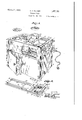
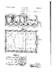
- Fig. l is a perspective view of a cabinet constructed in accordance with my invention for warming food and retaining the heat of cooked food, a side wall being partly broken away to disclose interior structure, two pocket lids being shown separated, a food vessel partlg removed from a pocket, and a Fig. 8 is a lon 'tudinal central vertical sectional view of t e food storage and heat or portion of the device.
- Fig. 4 is a cross sectional view of the storage and heater portion including a plan view or a perforate plate between the heater compartment and the food storage compartment.
- Fig. 5 is a fragmentary plan view of the heating unit.
- 1 designates a box-like base open at the top, and 2 a warming table housing positioned on the base and secured thereto by angle corner pieces 3 attached to the aligned vertical edges of the table and lease.
- the housing comprises side walls 4', walls 5 and 8, and a floor 3 all preferabl similarly formed of outer and inner sheath or sheets of metal 9 and i0, and insulatin material 11 being installed between the sheet to confer heat-retaining character on members.
- the outer sheets of the members are preferably formed integrally, and the inner sheets are similarly integral, provide an open topped receiver having no seams to the lines of connection.
- a top 12 is similarly formed of outer an inner sheets 13 and It, insulation therebetween and adapted to into th upper end of the open-tensed housing, the edges of the top sheets and wall sheets "being inter-locked as hy eriniping to sealingly gage the top the walls.
- the top is provided with a plurality of openings 16, and a horizontal vides the housing into up partments 18 and 19 to torn: respectively a food storage section to receive pot-like liners orpoclrets such as 20, 21, and 22 suspended in the o enings, and a heating section to receive a eating unit 23 adapted to he introduced through a door opening 24 in the end wall 5, all of which will be particularly described.
- er and lower comllhe partition 17 consists or" a plate formed the partition 1"? diheater to the pockets and to the upper compartment.
- the pockets have upper edges sealingly interlocked as by crimplng with the backturned edges of the outer sheet of the top at the openings to form seats 32 for" the peripheral flanges 33 of food containing vessels 34, 35, 36
- the pockets may rest on the plate, to receive heat directly therefrom, as well as through the openings thereof, but I prefer to space selected pockets from the plate for limiting the amount of heat transmitted to the bottoms of the pockets and admitting the heat to contact with the sides of the depending pockets inthe compartment.
- the openings 28 and 29 are provided in the offset portion of the partition plate, the former bein relatively numerous for admitt ng heat to tie relatively large vessel 34 WhlCh is adapted to contain meat, while the latter openings are adapted for the gravy pan 35.
- the vessels 36 positioned over the middle portion of the plate and heating compartment, would receive an excessive amount of heat, and a relatively small number of openings 30 is provided in each group associated with a vessel-containing pocket 21, whereby the proportion of available heat which is permitted to influence the pockets through the openings is limited.
- I further limit the heat influence on the pockets 21, and permit heated air to enter the compartment, by spacing sa1d pockets from the plate, and still further limlt. the heat 1nfiuence by inserting an insulating mat 39 between the plate and the pockets, and preferably seating the pockets on the mat. I arrange the openings 30 and position the pockets 21 so that portions of the pockets project laterally from the mat over the openings.
- the heating unit 23 as an electrical unit. comprising spaced angle irons 40 connected by straps 41 to form a supporting frame, the ends of the straps being downwardly offset and attached to the horizontal flanges-of the angle irons, and elongated heating elements 42 and 43 secured to the straps by bolts 44.
- the heating elements may be of ordinary "type in which energizing wires extend, the energizing circuit includin wires 45 and 46 connected with termina s 47 and 48 to which the socket 49 of a conductor 50 may be attached, and the terminals being supported in a head 51 fixed to the angle irons.
- a plate 52 on the head is ada ted to overlie the outer face of the end wal ad'acent the opening, and may be fixed thereto y bolts 53.
- thermostatic control or cutofi' 54 in the circuit In order to re'vent'overheatin of the compartments an food, and to rovlde for automatic control of heating, I mterpose a thermostatic control or cutofi' 54 in the circuit, and mount the same on a' shelf 55 clamped to the heating elements adjacent the outer end thereof and adapted to support the cutoff beneath the upwardly ofi'set portion of the plate, where adequate space is available and tllie cutofi may be relatively remote from the p ate.
- I further provide an indicating device to disclose the condition of the circult, com rising an electric lamp 56 mounted in the ead and connected in parallel with the cutoff in the circuit, whereby the lamp will glow when the circuit is closed, and breaking of the circuit by the cutofi' due to increase of heat in the heating compartment to a predetermined degree will suspend energization of the lam v
- the circuit wire 45 is preferably connected to a post 57 which constitutes the outer terminal of the wire in the heating element 42 and represents the same, and a wire 58 leads from the opposite terminal post 59 of the heating element wire to the cutoff.
- a wire 60 connects the post 57 with the wire terminal post 61 of the heating element 43, the op osite 10 wire terminal post 62 of said element ing connected by a wire 63 with the post 59, and the circuit being completed by the wire 46 from the cutofi to the terminal in the head.
- Wires 64 and 65 connected respectively with the posts 61 and 62 lead to the lamp for connecting the lamjiin parallel in the circuit.
- the device may e mounted on rollers 64 for convenient trans ortation.
- the light ceeses to glow the operator then at a suitable later time remove the cord in case the cebinet is Wanted for portoble use end move the some to another room. Should it be desired to vverin the food s cord may be con- 1 'F' 1 ,4 i nected Wlti'l e light socnet end with tne terminuls of the heating unit to raise the tempera ture in the heating chamber and restore the to the desired condition of warmth.
- Cords end light sockets may be available in widely sepereted locations so that the cabinot need not be returned to its original lccetion in order to reheet the'hesting chamber end the iced, and the operator may occupy himself with other business while the food is being reheated since the cutoi l will suiomatisally prevent the raising the temperature to undesirable extent,
- the thermostatic control may be of any desired construction end oriented for closing circuit to reenergize th heating element the temperature on? the chamber and food decline below e predetermined degree;
- e horizontal heat conducting plate dividing the cabinet into e heating chamber and a food storage chamber end having n plurality of heat directing openings, and a plurality of pockets supported in the storage chamber to receive heat passing through and directed by said openings from the heating chamber on predetermined portions thereof and adapted to support food-containing vessels,
- a conducting plate di viding the housing into a heating chamber and a food storage chamber and having a plurality of openings and on upwardly oilset portion, a plurality of pockets seated on the plate to receive heat passing through said openings from the heating chamber and a opted to support food containing vessels, and an insuluting sheet positioned on said plate below portions'oi selected pockets and obstructing the transfer of heat from the heating chamber to said ortions.
- a housing In a vverming table of the character describcd, a housing, a top fixed to the housing having a plurality of openings, a plate in the housing parallel with said top and having a plurality of groups of apertures related respectively to said top openings, end pockets suspended from the top in the top openings,
- a Warming table comprising at support, a housing including a food storage compartment and a heating compartment and having an opening in one wall, at heating unit adopted for introduction through the o ening and for support from the floor of the ousing in the heating compartment, a perforate plate supported from the walls or the housing between the compartments and having an upwardly ofiset portion forming an enlarged chamber portion of the heating compartment, and heat-responsive means sup orted by the heating unit in said chamber or controlling the heating unit.
- a housing in e Warming teble of the character described, a housing, a heat conducting plate having a plurality ofheat directing openings thcrethrough for dividing the housing into a heating chamber and s food storege chamber, a plurality of pockets seated on the plate to receive heat on certain portions passing through said heat directing openings in the plate from the heating chamber, food receiving vessels received in the pockets, end means for supporting the vessels in spaced relation with the Walls of the pockets to provide for distribution of heat over the Walls of the vessole.
- a housing e horizontal hoot conducting plate dividing the housing into a lowerheating chamber and an upper food storage chamber, a pluralit of-pockets seated on the the plate to receive eat passin throu h said plate from the heating cham er, an food receiving vessels received in and spaced from the walls of the pockets and havln flanges on their upK er ends for seating on t e walls of the poo ets.
- a warming table including a housing, a horizontal partition defining a heating chamber below the partition and a food storg5 age chamber above the partition, and having a plurality of openings arranged to form a group, and a top on the housing having an opening registerlng with said grou of openings in the partition, whereby heat 1s directed so to a predetermined portion of a vessel located in the opening of said top.
- a warming table including a housing having a top rovided with openin s, a horizontal partltion in the housing efinin a as. heating chamber below the partition an a food storage chamber above the partition, and having a group of openings below each of said top 0 enmgs, whereby predetermined portions 0 vessels located in said openings 40 may be heated, and an insulating sheet movable over the partition to close selected openings therein.
- a warming table including a housing having a horizontal artition defining storage and heating cham rs and having a group of heat directing openings therethrough, a top on the housing havin an opening, and a pocket member received 1n the opening havmg an upper open end secured to said top and to a closed bottom, the bottom of said pocket being positioned directly over said groi? of openings, thereby receiving more heat rom said heating chamber than the remainder of said pocket.
Description
March 22, 19332. H F ZAHNER L85J193 WARMING TABLE Filed Feb. 18, 1929 2 Sheets-Sheet -l LSSQAQJ March 22, 11932.
H. F. ZAHNER WARMING TABLE Filed Feb. 18, 1929 2 Sheets-Sheet 2 INVENTOR.
latented Mar. 22, 1%?
- UNITED TENT OFFICE My invention relates to heat-retaining food carriers and more particularly to warming tables for use in hospitals and restaurants for maintaining food in heated condition over 5 relatively long periods, and provided with hcatin means, the principal objects of the invention beins to facilitate and control the heating and reheating of heat retaining elements and food-containing vessels, to dis- 0 tribute heat suitably to the requirements of various types of food contained in the vessels, and to improve the ability of a device of this character to maintain the temper ature of the "food.
@rdinarily a device ada ted to maintain the temperature of cooked tood either is not provided with an activated source oi heat or must be moved from the source of heat to the location from which the food is served. 3 A further object of my invention therefore is to provide for heating and reheating the "food storage unit of a portable device, of this character, to facilitate the application oi a heating unit to the storage unit, and to i provide electrically energized heating units which may be operated at any position where a light socket is available.
Since it is not desirable to heat the food to cooking temperature in heat retaining storage devices and close constant attention to the heat e'dects to prevent overheating or wasteful expediture of heat energy, a fur ther object of my invention is to control the heating" unit for limiting the extent of heat production, and to provide means for indicating the rise of ten'lperature in the storage unit to the desired degree for retaining the heat of the cooked "food. in accomplishing these and other objects of theinvention, l have provided improved details of structure, the preferred forms of which are illustrated in the accompanying drawings, wherein:
Fig. l is a perspective view of a cabinet constructed in accordance with my invention for warming food and retaining the heat of cooked food, a side wall being partly broken away to disclose interior structure, two pocket lids being shown separated, a food vessel partlg removed from a pocket, and a Fig. 8 is a lon 'tudinal central vertical sectional view of t e food storage and heat or portion of the device.
Fig. 4 is a cross sectional view of the storage and heater portion including a plan view or a perforate plate between the heater compartment and the food storage compartment.
Fig. 5 is a fragmentary plan view of the heating unit.
Referring in detail to the drawings:
1 designates a box-like base open at the top, and 2 a warming table housing positioned on the base and secured thereto by angle corner pieces 3 attached to the aligned vertical edges of the table and lease.
The housing comprises side walls 4', walls 5 and 8, and a floor 3 all preferabl similarly formed of outer and inner sheath or sheets of metal 9 and i0, and insulatin material 11 being installed between the sheet to confer heat-retaining character on members. The outer sheets of the members are preferably formed integrally, and the inner sheets are similarly integral, provide an open topped receiver having no seams to the lines of connection.
A top 12 is similarly formed of outer an inner sheets 13 and It, insulation therebetween and adapted to into th upper end of the open-tensed housing, the edges of the top sheets and wall sheets "being inter-locked as hy eriniping to sealingly gage the top the walls.
The top is provided with a plurality of openings 16, and a horizontal vides the housing into up partments 18 and 19 to torn: respectively a food storage section to receive pot-like liners orpoclrets such as 20, 21, and 22 suspended in the o enings, and a heating section to receive a eating unit 23 adapted to he introduced through a door opening 24 in the end wall 5, all of which will be particularly described.
er and lower comllhe partition 17 consists or" a plate formed the partition 1"? diheater to the pockets and to the upper compartment.
The pockets have upper edges sealingly interlocked as by crimplng with the backturned edges of the outer sheet of the top at the openings to form seats 32 for" the peripheral flanges 33 of food containing vessels 34, 35, 36
and 37 having substantially smaller diameter and depth than the pockets whereby chambers 38' are formed between the vessels and the pockets when the vessels are suspended in the housing.
The pockets may rest on the plate, to receive heat directly therefrom, as well as through the openings thereof, but I prefer to space selected pockets from the plate for limiting the amount of heat transmitted to the bottoms of the pockets and admitting the heat to contact with the sides of the depending pockets inthe compartment.
The openings 28 and 29 are provided in the offset portion of the partition plate, the former bein relatively numerous for admitt ng heat to tie relatively large vessel 34 WhlCh is adapted to contain meat, while the latter openings are adapted for the gravy pan 35. The vessels 36, positioned over the middle portion of the plate and heating compartment, would receive an excessive amount of heat, and a relatively small number of openings 30 is provided in each group associated with a vessel-containing pocket 21, whereby the proportion of available heat which is permitted to influence the pockets through the openings is limited.
I further limit the heat influence on the pockets 21, and permit heated air to enter the compartment, by spacing sa1d pockets from the plate, and still further limlt. the heat 1nfiuence by inserting an insulating mat 39 between the plate and the pockets, and preferably seating the pockets on the mat. I arrange the openings 30 and position the pockets 21 so that portions of the pockets project laterally from the mat over the openings.
As the means for heating the compartments and the food, I preferably provide the heating unit 23 as an electrical unit. comprising spaced angle irons 40 connected by straps 41 to form a supporting frame, the ends of the straps being downwardly offset and attached to the horizontal flanges-of the angle irons, and elongated heating elements 42 and 43 secured to the straps by bolts 44. The heating elements may be of ordinary "type in which energizing wires extend, the energizing circuit includin wires 45 and 46 connected with termina s 47 and 48 to which the socket 49 of a conductor 50 may be attached, and the terminals being supported in a head 51 fixed to the angle irons. A plate 52 on the head is ada ted to overlie the outer face of the end wal ad'acent the opening, and may be fixed thereto y bolts 53.
In order to re'vent'overheatin of the compartments an food, and to rovlde for automatic control of heating, I mterpose a thermostatic control or cutofi' 54 in the circuit, and mount the same on a' shelf 55 clamped to the heating elements adjacent the outer end thereof and adapted to support the cutoff beneath the upwardly ofi'set portion of the plate, where adequate space is available and tllie cutofi may be relatively remote from the p ate.
I further provide an indicating device to disclose the condition of the circult, com rising an electric lamp 56 mounted in the ead and connected in parallel with the cutoff in the circuit, whereby the lamp will glow when the circuit is closed, and breaking of the circuit by the cutofi' due to increase of heat in the heating compartment to a predetermined degree will suspend energization of the lam v The circuit wire 45 is preferably connected to a post 57 which constitutes the outer terminal of the wire in the heating element 42 and represents the same, and a wire 58 leads from the opposite terminal post 59 of the heating element wire to the cutoff. A wire 60 connects the post 57 with the wire terminal post 61 of the heating element 43, the op osite 10 wire terminal post 62 of said element ing connected by a wire 63 with the post 59, and the circuit being completed by the wire 46 from the cutofi to the terminal in the head.
The device may e mounted on rollers 64 for convenient trans ortation.
In operating the evice, food is cooked in the usual manner and vessels containing the cooked food are installed in the pockets of the cabinet. Current is sup lied to the heating element and the. air in tiie heating chamber, and the plate, are heated. Heat is transmitted through the openings and plate to the pockets and food-containing vessels. The air in the chambers between the vessels and the pockets is retained by the relatively sealing engagement of the flanges of the vessels with the edges of the pockets so that when the chambers and plate are heated to a degree approximately-that of the vessels they will tend to preserve the desired temperature of the food inthe vessels.
When the heat has risen to a predetermined degree, the outed will operate to break the circuit and suspend heat production. While the circuit is closed, the light will be glowing so that an operator may by a. glance deter= 5 mine Whether the temperature has been raised to the desired degree. When the light ceeses to glow the operator then at a suitable later time remove the cord in case the cebinet is Wanted for portoble use end move the some to another room. Should it be desired to vverin the food s cord may be con- 1 'F' 1 ,4 i nected Wlti'l e light socnet end with tne terminuls of the heating unit to raise the tempera ture in the heating chamber and restore the to the desired condition of warmth. Cords end light sockets may be available in widely sepereted locations so that the cabinot need not be returned to its original lccetion in order to reheet the'hesting chamber end the iced, and the operator may occupy himself with other business while the food is being reheated since the cutoi l will suiomatisally prevent the raising the temperature to undesirable extent,
The thermostatic control may be of any desired construction end oriented for closing circuit to reenergize th heating element the temperature on? the chamber and food decline below e predetermined degree;
Particular attention is called to the remov= able character of the heatin section 23, which may be easily installed, an removed for re-= pair or replacement of parts, and to "which the heating unit, wires, and similar elements are connected. A substitute section may therefore be installed in a table when the section originslly installed therein must be removed for any reason. i
What I claim and desire to secure by Lettcrs Patent is:
1. In a cabinet of the character described, e horizontal heat conducting plate dividing the cabinet into e heating chamber and a food storage chamber end having n plurality of heat directing openings, and a plurality of pockets supported in the storage chamber to receive heat passing through and directed by said openings from the heating chamber on predetermined portions thereof and adapted to support food-containing vessels,
2. in a Warming table or" the character dcscribed, e housing, a conducting plate di= viding the housing into a heating chamber and a food storage chamber and having a plurality of openings and on upwardly oilset portion, a plurality of pockets seated on the plate to receive heat passing through said openings from the heating chamber and a opted to support food containing vessels, and an insuluting sheet positioned on said plate below portions'oi selected pockets and obstructing the transfer of heat from the heating chamber to said ortions.
3. in a device of the c aracter described, a housing, u horizontal conducting plate direscues &
viding the housing into n lower heating chamher and an upper food storage chamber end having e plurality of groups of o enings and an upwardly ofi'sct ortion, a p urelity of pockets suspended in t c store e chamber to receive heat passin verticel'y through said openings from t sheeting chamber, food-containing vessels adapted for mount= ing in the pockets, means for supportirn the vessels in spaced relation With the wal oi the pockets, and e heating unit, the housing havlng an opening in e vertical wall adja cent said offset portion oi the plate for admitting the heating unit to the heating chamber.
4:. In combination with e Warming table including a food storage compartment, e heating compartment, and a plurality of ves sels suspended in the food storage compartinent, a partition between the compartments having e plurality of openings differentially related to the several vessels for admitting different amounts or" heat to the several vesson.
5. In a vverming table of the character describcd, a housing, a top fixed to the housing having a plurality of openings, a plate in the housing parallel with said top and having a plurality of groups of apertures related respectively to said top openings, end pockets suspended from the top in the top openings,
selected pockets contacting the plate and closing the apertures related to the top openings in which the selected pockets are suspended.
6. A Warming table comprising at support, a housing including a food storage compartment and a heating compartment and having an opening in one wall, at heating unit adopted for introduction through the o ening and for support from the floor of the ousing in the heating compartment, a perforate plate supported from the walls or the housing between the compartments and having an upwardly ofiset portion forming an enlarged chamber portion of the heating compartment, and heat-responsive means sup orted by the heating unit in said chamber or controlling the heating unit.
7. in e Warming teble of the character described, a housing, a heat conducting plate having a plurality ofheat directing openings thcrethrough for dividing the housing into a heating chamber and s food storege chamber, a plurality of pockets seated on the plate to receive heat on certain portions passing through said heat directing openings in the plate from the heating chamber, food receiving vessels received in the pockets, end means for supporting the vessels in spaced relation with the Walls of the pockets to provide for distribution of heat over the Walls of the vessole.
8. In a Warming table of the character described, a housing, e horizontal hoot conducting plate dividing the housing into a lowerheating chamber and an upper food storage chamber, a pluralit of-pockets seated on the the plate to receive eat passin throu h said plate from the heating cham er, an food receiving vessels received in and spaced from the walls of the pockets and havln flanges on their upK er ends for seating on t e walls of the poo ets.
9. In a warming table of the character d'ew scribed, a housing, a conducting late dividin the housing mto a heatin c amber and a ood storage chamber and aving a lurality of openings, a plurality of poo ets seated on the plate to receive heat passing through said openings from the eating chamber and adapted to support food containing vessels, and an insulating sheet positioned on said late below portions of selected pockets and obstructing the transfer of heat from the heating chamber to said p0r= tions.
10. In a warming table including a housing, a horizontal partition defining a heating chamber below the partition and a food storg5 age chamber above the partition, and having a plurality of openings arranged to form a group, and a top on the housing having an opening registerlng with said grou of openings in the partition, whereby heat 1s directed so to a predetermined portion of a vessel located in the opening of said top.
11. In a warming table including a housing having a top rovided with openin s, a horizontal partltion in the housing efinin a as. heating chamber below the partition an a food storage chamber above the partition, and having a group of openings below each of said top 0 enmgs, whereby predetermined portions 0 vessels located in said openings 40 may be heated, and an insulating sheet movable over the partition to close selected openings therein.
12 A warming table including a housing having a horizontal artition defining storage and heating cham rs and having a group of heat directing openings therethrough, a top on the housing havin an opening, and a pocket member received 1n the opening havmg an upper open end secured to said top and to a closed bottom, the bottom of said pocket being positioned directly over said groi? of openings, thereby receiving more heat rom said heating chamber than the remainder of said pocket.
In testimony whereof I afiix my signature.
HENRY F..ZAHNER.
Priority Applications (1)
| Application Number | Priority Date | Filing Date | Title |
|---|---|---|---|
| US340896A US1850193A (en) | 1929-02-18 | 1929-02-18 | Warming table |
Applications Claiming Priority (1)
| Application Number | Priority Date | Filing Date | Title |
|---|---|---|---|
| US340896A US1850193A (en) | 1929-02-18 | 1929-02-18 | Warming table |
Publications (1)
| Publication Number | Publication Date |
|---|---|
| US1850193A true US1850193A (en) | 1932-03-22 |
Family
ID=23335383
Family Applications (1)
| Application Number | Title | Priority Date | Filing Date |
|---|---|---|---|
| US340896A Expired - Lifetime US1850193A (en) | 1929-02-18 | 1929-02-18 | Warming table |
Country Status (1)
| Country | Link |
|---|---|
| US (1) | US1850193A (en) |
Cited By (6)
| Publication number | Priority date | Publication date | Assignee | Title |
|---|---|---|---|---|
| US2478254A (en) * | 1944-02-10 | 1949-08-09 | Libbey Owens Ford Glass Co | Serving wagon |
| US2481384A (en) * | 1947-03-25 | 1949-09-06 | Wilfred E Blackwell | Portable electric steam table |
| US2563874A (en) * | 1948-09-29 | 1951-08-14 | Ruth F Salton | Mobile heated tray |
| US2564990A (en) * | 1949-08-08 | 1951-08-21 | Angelo C Parine | Combination sausage steamer and bun warmer |
| US4284880A (en) * | 1979-02-06 | 1981-08-18 | International Foodservice Equipment Systems, Inc. | Heating well |
| USD859906S1 (en) * | 2017-09-20 | 2019-09-17 | Campbell Soup Company | Soup bar |
-
1929
- 1929-02-18 US US340896A patent/US1850193A/en not_active Expired - Lifetime
Cited By (6)
| Publication number | Priority date | Publication date | Assignee | Title |
|---|---|---|---|---|
| US2478254A (en) * | 1944-02-10 | 1949-08-09 | Libbey Owens Ford Glass Co | Serving wagon |
| US2481384A (en) * | 1947-03-25 | 1949-09-06 | Wilfred E Blackwell | Portable electric steam table |
| US2563874A (en) * | 1948-09-29 | 1951-08-14 | Ruth F Salton | Mobile heated tray |
| US2564990A (en) * | 1949-08-08 | 1951-08-21 | Angelo C Parine | Combination sausage steamer and bun warmer |
| US4284880A (en) * | 1979-02-06 | 1981-08-18 | International Foodservice Equipment Systems, Inc. | Heating well |
| USD859906S1 (en) * | 2017-09-20 | 2019-09-17 | Campbell Soup Company | Soup bar |
Similar Documents
| Publication | Publication Date | Title |
|---|---|---|
| US1751219A (en) | Electric broiler | |
| US2257580A (en) | Electric cooking device | |
| US3270660A (en) | Cooking oven | |
| US3674982A (en) | Zone controlled cook oven | |
| US2416645A (en) | Combined deep well and surface burner electric cooker | |
| US1850193A (en) | Warming table | |
| US3120599A (en) | Open warmer | |
| US2984730A (en) | Multi-purpose cooking unit | |
| US1713303A (en) | Broiler | |
| US2063407A (en) | Electric heating device | |
| US3760155A (en) | Heating cabinet for treating nut meats | |
| US2222065A (en) | Combination combustion and electric stove | |
| US1392802A (en) | Electric fireless cooker and range | |
| US2009189A (en) | Portable stove | |
| US2077687A (en) | Portable electric cooking stove | |
| US2731539A (en) | Food heater and cooker | |
| US2174079A (en) | Heating device | |
| US2314592A (en) | Domestic appliance | |
| US2329592A (en) | Room heater | |
| US1534221A (en) | Electric floor heater | |
| US2261496A (en) | Electric heating unit | |
| US2004937A (en) | Portable electric cooker | |
| US2097977A (en) | Range | |
| US1358365A (en) | Meat-broiling machine | |
| US1612065A (en) | Electric range |