EP3251718A1 - Airway therapy apparatus - Google Patents
Airway therapy apparatus Download PDFInfo
- Publication number
- EP3251718A1 EP3251718A1 EP16172474.5A EP16172474A EP3251718A1 EP 3251718 A1 EP3251718 A1 EP 3251718A1 EP 16172474 A EP16172474 A EP 16172474A EP 3251718 A1 EP3251718 A1 EP 3251718A1
- Authority
- EP
- European Patent Office
- Prior art keywords
- hose
- passage channel
- free end
- therapy device
- respiratory therapy
- Prior art date
- Legal status (The legal status is an assumption and is not a legal conclusion. Google has not performed a legal analysis and makes no representation as to the accuracy of the status listed.)
- Granted
Links
Images


Classifications
-
- A—HUMAN NECESSITIES
- A61—MEDICAL OR VETERINARY SCIENCE; HYGIENE
- A61M—DEVICES FOR INTRODUCING MEDIA INTO, OR ONTO, THE BODY; DEVICES FOR TRANSDUCING BODY MEDIA OR FOR TAKING MEDIA FROM THE BODY; DEVICES FOR PRODUCING OR ENDING SLEEP OR STUPOR
- A61M16/00—Devices for influencing the respiratory system of patients by gas treatment, e.g. mouth-to-mouth respiration; Tracheal tubes
- A61M16/0003—Accessories therefor, e.g. sensors, vibrators, negative pressure
- A61M16/0006—Accessories therefor, e.g. sensors, vibrators, negative pressure with means for creating vibrations in patients' airways
-
- A—HUMAN NECESSITIES
- A61—MEDICAL OR VETERINARY SCIENCE; HYGIENE
- A61M—DEVICES FOR INTRODUCING MEDIA INTO, OR ONTO, THE BODY; DEVICES FOR TRANSDUCING BODY MEDIA OR FOR TAKING MEDIA FROM THE BODY; DEVICES FOR PRODUCING OR ENDING SLEEP OR STUPOR
- A61M16/00—Devices for influencing the respiratory system of patients by gas treatment, e.g. mouth-to-mouth respiration; Tracheal tubes
- A61M16/08—Bellows; Connecting tubes ; Water traps; Patient circuits
- A61M16/0816—Joints or connectors
-
- A—HUMAN NECESSITIES
- A61—MEDICAL OR VETERINARY SCIENCE; HYGIENE
- A61M—DEVICES FOR INTRODUCING MEDIA INTO, OR ONTO, THE BODY; DEVICES FOR TRANSDUCING BODY MEDIA OR FOR TAKING MEDIA FROM THE BODY; DEVICES FOR PRODUCING OR ENDING SLEEP OR STUPOR
- A61M16/00—Devices for influencing the respiratory system of patients by gas treatment, e.g. mouth-to-mouth respiration; Tracheal tubes
- A61M16/08—Bellows; Connecting tubes ; Water traps; Patient circuits
- A61M16/0875—Connecting tubes
-
- A—HUMAN NECESSITIES
- A61—MEDICAL OR VETERINARY SCIENCE; HYGIENE
- A61M—DEVICES FOR INTRODUCING MEDIA INTO, OR ONTO, THE BODY; DEVICES FOR TRANSDUCING BODY MEDIA OR FOR TAKING MEDIA FROM THE BODY; DEVICES FOR PRODUCING OR ENDING SLEEP OR STUPOR
- A61M16/00—Devices for influencing the respiratory system of patients by gas treatment, e.g. mouth-to-mouth respiration; Tracheal tubes
- A61M16/20—Valves specially adapted to medical respiratory devices
- A61M16/208—Non-controlled one-way valves, e.g. exhalation, check, pop-off non-rebreathing valves
-
- A—HUMAN NECESSITIES
- A61—MEDICAL OR VETERINARY SCIENCE; HYGIENE
- A61M—DEVICES FOR INTRODUCING MEDIA INTO, OR ONTO, THE BODY; DEVICES FOR TRANSDUCING BODY MEDIA OR FOR TAKING MEDIA FROM THE BODY; DEVICES FOR PRODUCING OR ENDING SLEEP OR STUPOR
- A61M39/00—Tubes, tube connectors, tube couplings, valves, access sites or the like, specially adapted for medical use
- A61M39/10—Tube connectors; Tube couplings
Definitions
- the invention relates to a respiratory therapy device according to the preamble of claim 1.
- Such a respiratory therapy device is the EP 2 087 927 A1 refer to.
- the respiratory therapy device is used to improve the breathing of a human and typically consists of a mouthpiece and a hose that is mounted on a spout on the mouthpiece.
- the hose is surrounded by a bent or curved pipe section, which dictates the curvature of the hose. When exhaling the breathing air is pressed into the tube and in response to the curvature of the pipe section this is excited to vibrate.
- Such respiratory therapy devices have proven themselves in practice versatile and are used to treat asthma patients with significant respiratory problems to top athletes to increase the lung volume and improve the respiratory process.
- the disadvantage has been found that the replacement of the hose requires a degree of dexterity, since the hose must be made of an elastic plastic on the spout of the pipe section or the mouthpiece. For this purpose, the hose must first be stretched in order to put the hose onto the nozzle in connection.
- the exchange provides the hose for patients with limited finger mobility or low dexterity is a major obstacle.
- the invention is therefore based on the object to provide a respiratory therapy device for the treatment of respiratory diseases of the aforementioned type, the hose is easy and simple, even for persons with limited finger mobility or dexterity, interchangeable, with the help of the patient, the respiratory tract at Ein- or exhale can train and thereby enters the desired therapeutic effect.
- the circumference of the first free end of the hose relative to the circumference of the passage channel from the free end of the pipe section is dimensioned smaller or equal that the width of one of the longitudinal sides of the first free end of the hose is sized larger than the width or the Diameter of the passageway of the free end of the pipe section that the hose is partially inserted by a compression of the longitudinal side in the passage channel and that the hose is held in the inserted state by a biasing force in the passage, the hose can easily and easily into the passage of the Pipe piece can also be used by persons with limited finger mobility or dexterity.
- the hose can be manually inserted without stretching by a slight compression or upsetting of the longitudinal sides in the pipe section.
- the tube After inserting and releasing the tube strives back because of its elastic properties in the initial shape and the long sides are by the state of tension against the passage channel pressed.
- the tube attaches to the passageway so that the exhaled breath air is directed into the tube and causes it to vibrate as it flows through.
- one or more projections are or are arranged on the side facing the passage channel at the first free end of the hose.
- the projections protrude to the outside of the hose and seal in the form of a lamellar seal in the inserted state, the air gap between the hose and the passageway. A flow of air through the air gap between the hose and the pipe section is thus largely prevented.
- one or more grooves or shoulders can be incorporated or worked advantageously in the region of the first free end of the hose, which also form a lamellar seal between the hose and the pipe section.
- the grooves can be adapted to the dimensions of the projections on the hose, so that the formations of the hose engage in the grooves. The hose is thus held on the one hand by the positive connection in the passage channel and on the other hand is achieved by the arrangement a good sealing effect of the disk seal.
- passage channel branch through at least one passage channel branch into a plurality of passage channel branches.
- a valve is arranged, which predetermines the flow direction in the respective passage channel branch.
- a hose In each of the passage channel branches can thus be used in coordination with the flow direction, a hose, so that the passage channel branches are alternately flowed through the valves during inhalation and exhalation and the respective tube oscillates.
- the tube is advantageously designed as a flat tube or oval-shaped tube.
- the passage is rotationally symmetrical, the width of the flat tube is sized larger than the diameter of the passage channel.
- the first free end of the tube may also be oval-shaped, wherein the circumference of the tube is equal to or equal to the circumference of the passage channel and the widest longitudinal side of the tube is sized larger than the diameter of the tube or vice versa.
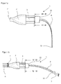
- FIG. 1 a is a respiratory therapy device 1 shown to improve the breathing of a patient, which is formed from a piece of pipe 3.
- the pipe section 3 has in the interior a cylindrical passage 4 with a diameter d.
- a mouthpiece 2 is attached, which on the one hand creates a pleasant oral intake of the respiratory therapy device 1 for the patient and on the other hand forms an opening for the passage channel 4.
- a hose 8 is partially inserted or inserted into the passageway 4.
- the respiratory therapy device 1 can be seen in the actuated state. Breathing air is injected into the passage 4 through the opening 7 of the mouthpiece 2 in a flow direction 6. The breath-air 5 flows through the passage 4 and passes through this into the tube 8. The air 5 expands at a sufficient flow of air, the tube 8 and puts this in an oscillating oscillation.
- the tube 8 can be easily joined to the passage channel 4 even for patients with limited finger mobility and does not accidentally slip out during use, the tube 8 is connected by a non-positive and / or positive connection or a biasing force in the passageway 4, as follows FIGS. 2a to 5 represented, held. After use of the respiratory therapy device 1, the hose 8 can be pulled out for cleaning purposes or for disposal from the passage channel 4 with only little effort.
- the tube 8 is this, and that is especially the FIGS. 2a and 2b can be seen as a flat tube 8 or oval tube (b »a) formed at the first free end 9 a plurality of projections 11 are formed or worked.
- a tubular seam 18 connects the respective lower and upper half of the flat tube 8 with each other.
- the inner sides of the tube 8 are provided with a release agent that prevents sticking together of the two inner sides of the tube 8.
- the tube 8 is made of an elastic material, preferably silicone.
- the width b - the distance between the two longitudinal sides 14 - of the hose 8 is dimensioned larger than the diameter d of the passage channel 4 and the length I of the hose 8 corresponds to the multiple of its width b.
- the flat tube 8 is compressed for insertion into the flow channel 4 at the first free end 9, so that the width b 'of the flat tube 8 is now smaller than the diameter d of the passage channel 4 (b>d>b').
- the tube 8 is then inserted in the passageway 4 partially inserted or introduced and as soon as this is released, the tube 8 strives back due to its elastic properties in the original shape.
- the diameter d of the passage channel 4 is dimensioned smaller than the width b of the tube 8 in the initial state, the longitudinal sides 14 of the tube 8 are pressed against the two opposite sides of the passage channel 4, whereby the frictional or frictional connection between the pipe section. 3 and the tube 8, as in the FIG. 3 shown, comes about.
- the two longitudinal sides 14 of the first free end 9 of the tube 8 are thus partially in the inserted state to the passageway 4 at.
- the hose 8 must be made of at least one elastic material and have sufficient rigidity I.
- the biasing force, which forms the frictional connection between the hose 8 and the passage 4 must be sufficiently large to keep the hose 8 in the passage 4 even at high flow rates or maximum breathing air pressure.
- the first free end of the tube 8 is inserted between 0.25d to 2d deep into the passageway 4, but this measurement may vary widely depending on numerous factors.
- Essential parameters are the preload force as a function of the elasticity and stiffness (EI) of the hose 8, the insertion depth and the friction between the tube 8 and passage 4.
- FIG. 5 can be seen that the tube 8 must be inserted at least as deep into the passageway 4 until all projections 11 abut the passageway 4.
- the insertion depth additionally can be indicated by markings on the tube 8.
- FIG. 6 shows a further embodiment of the respiratory therapy device 1, wherein in the passage channel 4 a plurality of grooves 12 are incorporated.
- the grooves 12 form the lamellar seal 13 of the air gap 16 between the passage channel 4 and the hose 8.
- they can be adapted to the dimensions of the projections 11 of the hose 8, so that the projections 11 in the inserted state of the hose 8 in the grooves 12th intervention.
- a positive connection is formed.
- the hose is thus on the one hand by the biasing force, which pressed the two longitudinal sides 14 against the two opposite sides of the passage channel, held and on the other hand by the positive connection between the projections 11 and the grooves 12th
- the grooves 12 may also be readily formed as paragraphs 17, which protrude from the pipe section 3 in the passageway 4.
- the paragraphs 17 can on the one hand form a stop for the tube 8 and / or on the other hand form the lamellar seal 13.
- the passage channel 4 of the pipe section 3 may be conical, the diameter d is continuously widened at the second free end, so that the tube 8 can be jammed in this during insertion.
- the respiratory therapy device 1 is formed from a plurality of pipe sections 3 which are modularly plugged together.
- the pipe sections 3 each have a plug-in device 25, which makes it possible to connect two pipe sections 3 airtight to each other.
- a passage channel branch 21 is arranged, which divides the passage channel 4 into a first and a second passage channel branch 22, 23.
- the pipe section 3 is placed on the mouthpiece 2 by means of the plug-in device 25 and has two valves 24 which predetermine a flow direction 6 for the respective passage channel branch 22, 23.
- the valve 24 closes in the first passageway branch 22 and the valve 24 in the second passageway branch 23 is opened so that the patient can both inhale and inhale with the respiratory therapy device 1.
- a second tube 8 can be arranged readily, the second free end 10 is directed in the passage 4 in the direction of the mouthpiece 2.
- the first free end 9 of the tube 8 may be conical, so that the inlet opening 15 of the tube 8 is slightly opened and has an opened inlet opening 15.
- the tube 8 or its first free end 9 is in Cross-section thus oval (a ⁇ b), wherein the width b of the tube 8 is greater than the diameter d of the passage channel 4 (b> d) and the circumference of the tube 8 is equal to or equal to the circumference of the passage channel 4 (2 * b ⁇ ⁇ * d).
- the passageway 4 may also have non-rotationally symmetrical cross-sectional shapes, e.g. have rectangular, triangular or the like.
- oval cross-sections whose width-height ratio (a: b) can be adapted to the opening ratio of the patient's mouth are readily possible.
- the circumference of the first free end 9 of the hose 8 is dimensioned smaller than the inner circumference of the pipe section 3 or as the circumference of the passage channel 8 and the width b of one of the longitudinal sides 14 of the hose 8 is dimensioned larger than the distance of the possible Contact points of the longitudinal sides 14 of the tube 8 in the passageway 4.
- the contact points are arranged on two opposite sides of the passageway, wherein a connecting line of the two points intersects the area center of the passageway.
Abstract
Bei einem Atemwegstherapiegerät (1) zur Behandlung von Atemwegserkrankungen bestehend aus mindestens einem Rohrstück (3), das mindestens einen Durchlasskanal (4) aufweist, durch den Luft (5) ein- bzw. ausatembar ist und mindestens einem elastischen Schlauch (8), dessen erstes freies Ende (9) an einem freien Ende an einem der Rohrstücke (3) angeordnet ist und beim Ein- bzw. Ausatmen in eine Strömungsrichtung (6) durch eine Durchströmung schwingen kann, soll der Schlauch (8) einfach und unkompliziert, auch für Personen mit eingeschränkter Fingermobilität oder Fingerfertigkeit, austauschbar sein. Diese Aufgabe ist dadurch gelöst, dass der Umfang des ersten freien Endes (9) des Schlauches (8) im Verhältnis zu dem Umfang des Durchlasskanals (4) von dem freien Ende des Rohrstücks (3) kleiner oder gleich groß bemessen ist, dass die Breite (b) einer der Längsseiten (14) des ersten freien Endes (9) des Schlauches (8) größer bemessen ist als die Breite bzw. der Durchmesser (d) des Durchlasskanals (4), dass der Schlauch (8) durch Stauchung der Längsseite (14) in den Durchlasskanals (4) bereichsweise einsteckbar ist und dass der Schlauch (8) im eingesetzten Zustand durch eine Vorspannkraft in dem Durchlasskanal (4) gehalten ist.In a respiratory therapy device (1) for the treatment of respiratory diseases comprising at least one tube piece (3) having at least one passage channel (4) through which air (5) can be inhaled or exhaled and at least one elastic tube (8) whose first free end (9) at a free end on one of the pipe sections (3) is arranged and when breathing in and out in a flow direction (6) can oscillate through a flow, the hose (8) simple and straightforward, even for Persons with limited finger mobility or dexterity, be interchangeable. This object is achieved in that the circumference of the first free end (9) of the hose (8) in relation to the circumference of the passage channel (4) from the free end of the pipe section (3) is dimensioned smaller or equal that the width (b) one of the longitudinal sides (14) of the first free end (9) of the hose (8) is dimensioned larger than the width or the diameter (d) of the passage channel (4) that the hose (8) by compression of the longitudinal side (14) in the passage channel (4) is partially inserted and that the hose (8) in the inserted state by a biasing force in the passageway (4) is held.
Description
Die Erfindung bezieht sich auf ein Atemwegstherapiegerät nach dem Oberbegriff des Patentanspruches 1.The invention relates to a respiratory therapy device according to the preamble of
Ein derartiges Atemwegstherapiegerät ist der
Derartige Atemwegstherapiegeräte haben sich in der Praxis vielseitig bewährt und werden zur Therapie von Asthma-Patienten mit erheblichen Atemwegsproblemen bis hin zum Spitzensportler zur Vergrößerung des Lungenvolumens und zur Verbesserung des Atmungsvorganges verwendet.Such respiratory therapy devices have proven themselves in practice versatile and are used to treat asthma patients with significant respiratory problems to top athletes to increase the lung volume and improve the respiratory process.
Nachteiligerweise hat sich jedoch herausgestellt, dass der Austausch des Schlauches ein gewisses Maß an Fingerfertigkeit voraussetzt, da der Schlauch aus einem elastischen Kunststoff auf die Tülle des Rohrstückes bzw. des Mundstückes aufgezogen werden muss. Hierzu muss der Schlauch zunächst aufgedehnt werden um in Anschluss den Schlauch auf die Tülle zu stülpen. Insbesondere stellt der Austausch des Schlauches für Patienten mit eingeschränkter Fingermobilität oder einer geringen Fingerfertigkeit ein wesentliches Hindernis dar.The disadvantage, however, has been found that the replacement of the hose requires a degree of dexterity, since the hose must be made of an elastic plastic on the spout of the pipe section or the mouthpiece. For this purpose, the hose must first be stretched in order to put the hose onto the nozzle in connection. In particular, the exchange provides the hose for patients with limited finger mobility or low dexterity is a major obstacle.
Der Erfindung liegt daher die Aufgabe zugrunde, ein Atemwegstherapiegerät zur Behandlung von Atemwegserkrankungen der vorgenannten Gattung zur Verfügung zu stellen, dessen Schlauch einfach und unkompliziert, auch für Personen mit eingeschränkter Fingermobilität oder Fingerfertigkeit, austauschbar ist, mit dessen Hilfe der Patient die Atemwege beim Ein- bzw. Ausatmen trainieren kann und dadurch der gewünschte Therapieeffekt eintritt.The invention is therefore based on the object to provide a respiratory therapy device for the treatment of respiratory diseases of the aforementioned type, the hose is easy and simple, even for persons with limited finger mobility or dexterity, interchangeable, with the help of the patient, the respiratory tract at Ein- or exhale can train and thereby enters the desired therapeutic effect.
Darüber hinaus ist es Aufgabe der Erfindung, ein Atemwegstherapiegerät bereit zu stellen, dessen einzelne Komponenten kostengünstig, einfach zu handhaben und benutzerfreundlich zu reinigen bzw. zu sterilisieren sind.In addition, it is an object of the invention to provide a respiratory therapy device whose individual components are inexpensive, easy to handle and user-friendly to clean or sterilize.
Diese Aufgaben werden durch die Merkmale des kennzeichnenden Teils von Patentanspruch 1 gelöst.These objects are achieved by the features of the characterizing part of
Weitere vorteilhafte Weiterbildungen der Erfindung ergeben sich aus den Unteransprüchen.Further advantageous developments of the invention will become apparent from the dependent claims.
Dadurch dass der Umfang des ersten freien Endes des Schlauches im Verhältnis zu dem Umfang des Durchlasskanals von dem freien Ende des Rohrstücks kleiner oder gleich bemessen ist, dass die Breite einer der Längsseiten des ersten freien Endes des Schlauches größer bemessen ist als die Breite bzw. der Durchmesser des Durchlasskanals von dem freien Ende des Rohrstücks, dass der Schlauch durch eine Stauchung der Längsseite in den Durchlasskanals bereichsweise einsteckbar ist und dass der Schlauch im eingesetzten Zustand durch eine Vorspannkraft in dem Durchlasskanal gehalten ist, kann der Schlauch einfach und unkompliziert in den Durchlasskanal des Rohrstückes auch von Personen mit eingeschränkter Fingermobilität oder Fingerfertigkeit eingesetzt werden. Der Schlauch kann manuell ohne ein Aufdehnen durch ein geringfügiges Zusammendrücken bzw. Stauchen der Längsseiten in das Rohrstück eingesetzt werden. Nach dem Einsetzten und dem Loslassen streb der Schlauch aufgrund seiner elastischen Eigenschaften in die Ausgangsform zurück und die Längsseiten werden durch den Spannungszustand gegen den Durchlasskanal gedrückt. Der Schlauch legt sich an den Durchlasskanal an, so dass die ausgeatmete Atem-Luft in den Schlauch geleitet ist und diesen beim Durchströmen zum Schwingen bringt.Characterized in that the circumference of the first free end of the hose relative to the circumference of the passage channel from the free end of the pipe section is dimensioned smaller or equal that the width of one of the longitudinal sides of the first free end of the hose is sized larger than the width or the Diameter of the passageway of the free end of the pipe section that the hose is partially inserted by a compression of the longitudinal side in the passage channel and that the hose is held in the inserted state by a biasing force in the passage, the hose can easily and easily into the passage of the Pipe piece can also be used by persons with limited finger mobility or dexterity. The hose can be manually inserted without stretching by a slight compression or upsetting of the longitudinal sides in the pipe section. After inserting and releasing the tube strives back because of its elastic properties in the initial shape and the long sides are by the state of tension against the passage channel pressed. The tube attaches to the passageway so that the exhaled breath air is directed into the tube and causes it to vibrate as it flows through.
Darüber hinaus hat es sich als vorteilhaft erwiesen, dass an dem ersten freien Ende des Schlauches, auf der dem Durchlasskanal zugewandten Seite, eine oder mehrere Anformungen angeordnet ist bzw. sind. Die Anformungen stehen nach Außen von dem Schlauch ab und dichten in Form einer Lamellendichtung im eingesetzten Zustand den Luftspalt zwischen dem Schlauch und dem Durchlasskanal. Ein Durchströmen der Atemluft durch den Luftspalt zwischen dem Schlauch und dem Rohrstück ist somit weitestgehend verhindert.Moreover, it has proved to be advantageous that one or more projections are or are arranged on the side facing the passage channel at the first free end of the hose. The projections protrude to the outside of the hose and seal in the form of a lamellar seal in the inserted state, the air gap between the hose and the passageway. A flow of air through the air gap between the hose and the pipe section is thus largely prevented.
In dem Durchlasskanal können vorteilhafterweise im Bereich des ersten freien Endes des Schlauches ein oder mehrere Nuten oder Absätze eingearbeitet bzw. angearbeitet sein, die ebenfalls eine Lamellendichtung zwischen dem Schlauch und dem Rohrstück bilden. Ferner können die Nuten an die Abmessungen der Anformungen an dem Schlauch angepasst sein, so dass die Anformungen des Schlauches in die Nuten greifen. Der Schlauch ist somit einerseits durch den Formschluss in dem Durchlasskanal gehalten und zum anderen ist durch die Anordnung eine gute Dichtwirkung der Lamellendichtung erreicht.In the passageway, one or more grooves or shoulders can be incorporated or worked advantageously in the region of the first free end of the hose, which also form a lamellar seal between the hose and the pipe section. Furthermore, the grooves can be adapted to the dimensions of the projections on the hose, so that the formations of the hose engage in the grooves. The hose is thus held on the one hand by the positive connection in the passage channel and on the other hand is achieved by the arrangement a good sealing effect of the disk seal.
Weiterhin hat es sich als vorteilhaft erwiesen, den Durchlasskanal durch mindestens eine Durchlasskanalabzweigung in mehrere Durchlasskanalzweige zu teilen. In jeden der Durchlasskanalzweige ist ein Ventil angeordnet, das die Strömungsrichtung in dem jeweiligen Durchlasskanalzweig vorgibt. In jedem der Durchlasskanalzweige kann somit in Abstimmung mit der Strömungsrichtung ein Schlauch eingesetzt sein, so dass die Durchlasskanalzweige wechselseitig durch die Ventile beim Ein- bzw. Ausatmen durchströmt sind und der jeweilige Schlauch schwingt.Furthermore, it has proved to be advantageous to divide the passage channel through at least one passage channel branch into a plurality of passage channel branches. In each of the passage channel branches, a valve is arranged, which predetermines the flow direction in the respective passage channel branch. In each of the passage channel branches can thus be used in coordination with the flow direction, a hose, so that the passage channel branches are alternately flowed through the valves during inhalation and exhalation and the respective tube oscillates.
Der Schlauch ist vorteilhafterweise als Flach-Schlauch oder oval-förmiger Schlauch ausgebildet. Der Durchlasskanal ist dafür rotationsymmetrisch, wobei die Breite des Flachschlauches größer bemessen ist als der Durchmesser des Durchlasskanals.The tube is advantageously designed as a flat tube or oval-shaped tube. The passage is rotationally symmetrical, the width of the flat tube is sized larger than the diameter of the passage channel.
Das erste freie Ende des Schlauchs kann auch oval -förmig sein, wobei der Umfang des Schlauches keiner oder gleich dem Umfang des Durchlasskanals ist und die breiteste Längsseite des Schlauches größer bemessen ist als der Durchmesser des Schlauches oder vice versa.The first free end of the tube may also be oval-shaped, wherein the circumference of the tube is equal to or equal to the circumference of the passage channel and the widest longitudinal side of the tube is sized larger than the diameter of the tube or vice versa.
In der Zeichnung sind ein erfindungsgemäßes Ausführungsbeispiel und zwei weitere Ausführungsvarianten dargestellt, die nachfolgend näher erläutert sind. Im Einzelnen zeigt:
- Figur 1 a
- ein Atemwegstherapiegerät mit einem Rohrstück, das einen Durchlasskanal bildet, an dessen ersten freien Ende ein Mundstück angearbeitet bzw. angeformt ist und ein Schlauch in den Durchlasskanal des zweiten freien Endes eingesetzt ist,
- Figur 1b
- das Atemwegstherapiegerät gemäß
Figur 1a , wobei Atemluft in Strömungsrichtung durch das Mundstück eingeblasen ist und der Schlauch zum Schwingen angeregt ist, - Figur 2a und 2b
- Drauf- und Seitenansicht des Schlauches gemäß
Figur 1 a, Figur 3- eine Schnittdarstellung quer zur Strömungsrichtung gemäß
Figur 1 a, Figur 4- eine Schnittdarstellung quer zur Strömungsrichtung gemäß
Figur 1b , Figur 5- eine Schnittdarstellung des Atemwegstherapiegerätes gemäß
Figur 1 a, Figur 6- Schnittdarstellung einer zweiten Ausführungsvariante gemäß
Figur 1a mit in den Durchlasskanal eingearbeiteten Nuten, in die von dem Schlauch abstehende Anformungen eingreifen und Figur 7- eine dritte Ausführungsvariante des erfindungsgemäßen Atemwegstherapiegerätes mit einer Durchlasskanalabzweigung und zwei Ventilen, die jeweils beim Ein- bzw. Ausblasen und vice versa den jeweiligen Kanalzweig durchströmen lassen.
- FIG. 1 a
- a respiratory therapy device comprising a tube piece forming a passageway at the first free end of which a mouthpiece is machined and a tube inserted into the passageway of the second free end,
- FIG. 1b
- the respiratory therapy device according to
FIG. 1a wherein breathing air is blown in the direction of flow through the mouthpiece and the tube is excited to vibrate, - FIGS. 2a and 2b
- Top and side view of the hose according to
FIG. 1 a, - FIG. 3
- a sectional view transverse to the flow direction according to
FIG. 1 a, - FIG. 4
- a sectional view transverse to the flow direction according to
FIG. 1b . - FIG. 5
- a sectional view of the respiratory therapy device according to
FIG. 1 a, - FIG. 6
- Sectional view of a second embodiment according to
FIG. 1a with incorporated in the passageway grooves in which protrude from the hose protrusions and - FIG. 7
- a third embodiment of the respiratory therapy device according to the invention with a Durchlasskanalabzweigung and two valves, each flow through the respective channel branch when blowing in and out and vice versa.
In
Der
Damit der Schlauch 8 auch für Patienten mit eingeschränkter Fingermobilität unkompliziert mit dem Durchlasskanal 4 zusammenführbar ist und bei Benutzung nicht ungewollt herausrutscht, ist der Schlauch 8 durch eine kraft- und/oder formschlüssige Verbindung bzw. eine Vorspannkraft in dem Durchlasskanal 4, wie nachfolgend durch die
Der Schlauch 8 hierzu ist, und das ist insbesondere den
Der Schlauch 8 ist aus einem elastischen Material, vorzugweise Silikon, hergestellt. Die Breite b - der Abstand zwischen den beiden Längsseiten 14 - des Schlauches 8 ist größer bemessen als der Durchmesser d des Durchlasskanals 4 und die Länge I des Schlauches 8 entspricht dem Vielfachen seiner Breite b.The
Der Flach-Schlauch 8 wird zum Einführen in den Durchflusskanal 4 an dem ersten freien Ende 9 zusammengedrückt, so dass die Breite b' des Flach-Schlauches 8 nunmehr kleiner ist als der Durchmesser d des Durchlasskanals 4 (b>d>b'). Der Schlauch 8 wird anschließend in den Durchlasskanal 4 bereichsweise eingesteckt bzw. eingeführt und sobald dieser losgelassen ist, strebt der Schlauch 8 aufgrund seiner elastischen Eigenschaften in die ursprüngliche Form zurück. Da jedoch der Durchmesser d des Durchlasskanals 4 kleiner bemessen ist als die Breite b des Schlauches 8 im Ausgangszustand, werden die Längsseiten 14 des Schlauches 8 gegen die beiden sich gegenüberliegenden Seiten des Durchlasskanals 4 gepresst, wodurch die kraftschlüssige bzw. reibschlüssige Verbindung zwischen dem Rohrstück 3 und dem Schlauch 8, so wie in der
Der Schlauch 8 muss hierfür aus mindestens einem elastischen Werkstoff hergestellt sein und ein ausreichende Steifigkeit I aufweisen. Die die Vorspannkraft, die die kraftschlüssige Verbindung zwischen dem Schlauch 8 und dem Durchlasskanal 4 bildet, muss ausreichend groß bemessen, um den Schlauch 8 auch bei hohen Durchströmungsgeschwindigkeiten bzw. maximalen Atemluft-Druck in dem Durchlasskanal 4 zu halten.For this purpose, the
Typischer Weise ist das erste freie Ende des Schlauches 8 zwischen 0,25d bis 2d tief in den Durchlasskanal 4 eingesteckt, jedoch kann diese Maßangabe in Abhängigkeit von zahlreichen Faktoren stark variieren. Wesentliche Parameter sind die Vorspannkraft als eine Funktion von der Elastizität und Steifigkeit (EI) des Schlauches 8, der Einstecktiefe und den Reibung zwischen Schlauch 8 und Durchlasskanal 4.Typically, the first free end of the
Durch das Zusammendrücken der Längsseiten 14 vor dem Einsetzen des Flach-Schlauches 8 in den Durchlasskanal 4 ist die obere und untere Seite an dem ersten freien Ende 9 voneinander getrennt und es bildet sich eine Einlassöffnung 15 im Schlauch 8. Beim Ausatmen, und dies ist insbesondere der
Aufgrund der Ausgestaltung des Schlauches 8 ist nach wie vor ein geringfügiger Luftspalt 16 zwischen dem Schlauch 8 und den Durchlasskanal 4 vorhanden, da der Umfang des Schlauches 8 kleiner bemessen ist, als der Umfang des Durchlasskanals 4. Um diesen Luftspalt 16 bestmöglich zu dichten, sind auf der dem Durchlasskanal 4 zugewandten Seite des Schlauches 8 mehrere Anformungen 11 angeformt, die nach Art einer Lamellendichtung 13 den Luftspalt 16 bestmöglich dichten.Due to the design of the
Insbesondere ist der
Der
Der Schlauch wird folglich einerseits durch die Vorspannkraft, die die beiden Längsseiten 14 gegen die beiden sich gegenüberliegenden Seiten des Durchlasskanals gepresst, gehalten und anderseits durch den Formschluss zwischen den Anformungen 11 und den Nuten 12.The hose is thus on the one hand by the biasing force, which pressed the two
Die Nuten 12 können auch ohne weiteres als Absätze 17 ausgebildet sein, die aus dem Rohrstück 3 in den Durchlasskanal 4 ragen. Die Absätze 17 können einerseits einen Anschlag für den Schlauch 8 bilden und/oder andererseits die Lamellendichtung 13 formen.The
Alternativ kann der Durchlasskanal 4 des Rohrstückes 3 konisch ausgebildet sein, dessen Durchmesser d am zweiten freien Ende kontinuierlich aufgeweitet ist, so dass der Schlauch 8 in diesem beim Einführen verklemmt werden kann.Alternatively, the
Der
In einem der dem Rohrstück 3 eine Durchlasskanal-Abzweigung 21 angeordnet ist, die den Durchlasskanal 4 in einen ersten und einen zweiten Durchlasskanal-Zweig 22, 23 aufteilt. Das Rohrstück 3 ist mittels der Steckeinrichtung 25 auf das Mundstück 2 aufgesetzt und weist zwei Ventile 24 auf, die dem jeweiligen DurchlasskanalZweig 22, 23 eine Strömungsrichtung 6 vorgeben. Demnach ist beim Ausatmen durch die Ventile 24 der erste Durchlasskanal-Zweig 22 freigegeben und die AtemLuft 5 ist durch den ersten Durchlasskanal-Zweig 22 zu dem Schlauch 8 geleitet. Beim Einatmen schließt das Ventil 24 in dem ersten Durchlasskanal-Zweig 22 und das Ventil 24 in dem zweiten Durchlasskanal-Zweig 23 ist geöffnet, so dass der Patient mit dem Atemwegstherapiegerät 1 sowohl aus- als auch einatmen kann.In one of the
In dem zweiten Durchlasskanal-Zweig 23 kann ohne weiteres ein zweiter Schlauch 8 angeordnet sein, dessen zweites freies Ende 10 im Durchlasskanal 4 in Richtung des Mundstückes 2 gerichtet ist.In the second passage channel branch 23, a
Das erste freie Ende 9 des Schlauches 8 kann konisch ausgebildet sein, so dass die Einlasssöffnung 15 des Schlauches 8 geringfügig geöffnet ist und eine geöffnete Einlassöffnung 15 aufweist. Der Schlauch 8 bzw. dessen erstes freies Ende 9 ist im Querschnitt somit oval (a<b), wobei die Breite b des Schlauches 8 größer ist als der Durchmesser d des Durchlasskanals 4 (b>d) und der Umfang des Schlauches 8 keiner oder gleich dem Umfang des Durchlasskanals 4 ist (2*b ≤ Π*d).The first
Der Durchlasskanal 4 kann auch nicht rotationssymmetrische Querschnittformen z.B. rechteckig, dreieckig oder dergleichen aufweisen. Ohne Weiteres sind insbesondere ovale Querschnitte möglich deren Verhältnis Breite:Höhe (a:b) auf das Öffnungsverhältnis des Mundes des Patienten angepasst sein kann.The
Wesentlich ist, dass der Umfang des ersten freien Endes 9 des Schlauches 8 kleiner dimensioniert ist als der Innenumfang des Rohrstückes 3 bzw. als der Umfang des Durchlasskanals 8 und die Breite b einer der Längsseiten 14 des Schlauches 8 größer bemessen ist als der Abstand der möglichen Kontaktpunkte der Längsseiten 14 des Schlauches 8 in dem Durchlasskanal 4. Die Kontaktpunkte sind auf zwei gegenüberliegenden Seiten des Durchlasskanals angeordnet, wobei eine Verbindungslinie der beiden Punkte den Flächenmittelpunkt des Durchlasskanals schneidet.It is essential that the circumference of the first
Claims (10)
dass der Umfang des ersten freien Endes (9) des Schlauches (8) im Verhältnis zu dem Umfang des Durchlasskanals (4) von dem freien Ende des Rohrstücks (3) kleiner oder gleich groß bemessen ist, dass die Breite (b) einer der Längsseiten (14) des ersten freien Endes (9) des Schlauches (8) größer bemessen ist als die Breite bzw. der Durchmesser (d) des Durchlasskanals (4), dass der Schlauch (8) durch Stauchung der Längsseite (14) in den Durchlasskanals (4) bereichsweise einsteckbar ist und dass der Schlauch (8) im eingesetzten Zustand durch eine Vorspannkraft in dem Durchlasskanal (4) gehalten ist.Respiratory therapy device (1) for the treatment of respiratory diseases consisting of:
in that the circumference of the first free end (9) of the hose (8) is dimensioned smaller or equal in relation to the circumference of the passage channel (4) from the free end of the pipe section (3) such that the width (b) of one of the longitudinal sides (14) of the first free end (9) of the hose (8) is dimensioned larger than the width or the diameter (d) of the passage channel (4) that the hose (8) by compression of the longitudinal side (14) in the passage channel (4) can be inserted in certain areas and that the hose (8) is inserted in the Condition is held by a biasing force in the passageway (4).
dadurch gekennzeichnet,
dass an dem ersten freien Ende (9) des Schlauchs (8) auf der dem Durchlasskanal (4) zugewandten Seite ein oder mehrere Anformungen (11) angeordnet sind und dass die Anformungen (11) in dem Durchlasskanal (4) eine lamellendichtung (12) bilden.Respiratory therapy device (1) according to claim 1
characterized,
in that one or more projections (11) are arranged on the first free end (9) of the tube (8) on the side facing the passage channel (4), and in that the projections (11) in the passage channel (4) form a lamellar seal (12). form.
dadurch gekennzeichnet,
dass in dem Durchlasskanal (4) im Bereich des ersten freien Endes (9) des Schlauches (8) ein oder mehrere Nuten (12) eingearbeitet sind und dass die Nuten (12) in dem Durchlasskanals (4) die Lamellendichtung (13) zwischen dem Schlauch (8) und dem Rohrstück (3) bilden.Respiratory therapy device (1) according to claim 2
characterized,
in that one or more grooves (12) are incorporated in the passage (4) in the region of the first free end (9) of the hose (8), and in that the grooves (12) in the passage (4) form the disk seal (13) between the two Hose (8) and the pipe section (3) form.
dadurch gekennzeichnet,
dass die Nut (12) an die Abmessungen der Anformung (11) an dem Schlauch (8) angepasst ist, dass die Anformung (11) in die Nut (12) eingreift und dass der Schlauch (8) durch den Formschluss zwischen der Anformung (11) und der Nut (12) in dem Durchlasskanal (4) gehalten ist.Respiratory therapy device (1) according to one of claims 2 or 3,
characterized,
that the groove (12) is adapted to the dimensions of the Anformung (11) on the hose (8), that the Anformung (11) engages in the groove (12) and that the hose (8) by the positive connection between the Anformung ( 11) and the groove (12) is held in the passageway (4).
dadurch gekennzeichnet,
dass das erste freien Ende (9) des Schlauchs (8) eine Trichterform aufweist und dass durch die Trichterform eine Einlassöffnung (15) gebildet ist.Respiratory therapy device (1) according to one of the preceding claims
characterized,
in that the first free end (9) of the tube (8) has a funnel shape and that an inlet opening (15) is formed by the funnel shape.
dadurch gekennzeichnet,
dass der Durchlasskanal (4) durch mindestens eine DurchlasskanalAbzweigung (21) in mehrere Durchlasskanalzweige (22, 23) unterteilt ist, dass in jedem der Durchlasskanalzweig (22, 23) ein Ventil (24) angeordnet ist und dass durch das Ventil (24) die Strömungsrichtung (5) in dem jeweiligen Rohrstücken (3) vorgegeben ist.Respiratory therapy device (1) according to one of the preceding claims
characterized,
in that the passage channel (4) is subdivided into a plurality of passage channel branches (22, 23) by at least one passage channel branch (21), that a valve (24) is arranged in each of the passage channel branches (22, 23) and that the valve (24) is arranged through the valve (24) Flow direction (5) in the respective pipe sections (3) is predetermined.
dadurch gekennzeichnet,
dass in jeden der Durchlasskanalzweige (22, 23) ein Schlauch (8) eingesetzt ist und dass zwei der Durchlasskanalzweige (22, 23) wechselseitig durch das Ventil (24) beim Ein- bzw. Ausatmen durchströmt sind und der jeweilige Schlauch (8) schwingt..Respiratory therapy device (1) according to claim 6
characterized,
that in each of the passage channel branches (22, 23), a hose (8) is inserted and that two of the Durchlasskanalzweige (22, 23) alternately through the valve (24) when inhaling and exhaling flow through and the respective hose (8) oscillates ..
dadurch gekennzeichnet,
dass der Schlauch (8) als flach- oder oval förmiger Schlauch (8) geformt ist..Respiratory therapy device (1) according to one of the preceding claims
characterized,
that the hose (8) as a flat or oval-shaped tube (8) is formed ..
dadurch gekennzeichnet,
dass der Schlauch (8) aus Silikon hergestellt ist.Respiratory therapy device (1) according to one of the preceding claims
characterized,
that the hose (8) is made of silicone.
dadurch gekennzeichnet,
dass an einem der Rohrstücke (3) ein Mundstück (2) angeordnet ist.Respiratory therapy device (1) according to one of the preceding claims
characterized,
in that a mouthpiece (2) is arranged on one of the pipe sections (3).
Priority Applications (7)
| Application Number | Priority Date | Filing Date | Title |
|---|---|---|---|
| EP16172474.5A EP3251718B1 (en) | 2016-06-01 | 2016-06-01 | Airway therapy apparatus |
| JP2017093789A JP2017213362A (en) | 2016-06-01 | 2017-05-10 | Airway treatment device |
| US15/606,053 US11110237B2 (en) | 2016-06-01 | 2017-05-26 | Therapeutic device for respiratory passages |
| AU2017203639A AU2017203639B2 (en) | 2016-06-01 | 2017-05-30 | Therapeutic device for respiratory passages |
| CA2969087A CA2969087A1 (en) | 2016-06-01 | 2017-05-31 | Therapeutic device for respiratory passages |
| CN201710403751.1A CN107432972A (en) | 2016-06-01 | 2017-06-01 | Respiratory tract therapeutic instrument |
| MX2017007023A MX2017007023A (en) | 2016-06-01 | 2017-06-05 | Therapeutic device for respiratory passages. |
Applications Claiming Priority (1)
| Application Number | Priority Date | Filing Date | Title |
|---|---|---|---|
| EP16172474.5A EP3251718B1 (en) | 2016-06-01 | 2016-06-01 | Airway therapy apparatus |
Publications (3)
| Publication Number | Publication Date |
|---|---|
| EP3251718A1 true EP3251718A1 (en) | 2017-12-06 |
| EP3251718A8 EP3251718A8 (en) | 2018-01-03 |
| EP3251718B1 EP3251718B1 (en) | 2018-08-15 |
Family
ID=56132757
Family Applications (1)
| Application Number | Title | Priority Date | Filing Date |
|---|---|---|---|
| EP16172474.5A Active EP3251718B1 (en) | 2016-06-01 | 2016-06-01 | Airway therapy apparatus |
Country Status (7)
| Country | Link |
|---|---|
| US (1) | US11110237B2 (en) |
| EP (1) | EP3251718B1 (en) |
| JP (1) | JP2017213362A (en) |
| CN (1) | CN107432972A (en) |
| AU (1) | AU2017203639B2 (en) |
| CA (1) | CA2969087A1 (en) |
| MX (1) | MX2017007023A (en) |
Families Citing this family (1)
| Publication number | Priority date | Publication date | Assignee | Title |
|---|---|---|---|---|
| EP3954418A1 (en) | 2020-08-11 | 2022-02-16 | CEGLA Medizintechnik GmbH & Co. KG | Respiratory therapy apparatus |
Citations (6)
| Publication number | Priority date | Publication date | Assignee | Title |
|---|---|---|---|---|
| US4557261A (en) * | 1980-12-20 | 1985-12-10 | Ruegheimer Erich | Connection system for fluid lines having telescoping connecting elements, in particular for respirators or anesthetic units |
| WO1998024500A1 (en) * | 1996-12-03 | 1998-06-11 | Bernard Janusz Liban | Endotracheal tube connector |
| EP2087927A1 (en) | 2008-02-08 | 2009-08-12 | R. Cegla GmbH & Co. KG | Therapy device |
| US20130160888A1 (en) * | 2011-12-22 | 2013-06-27 | General Electric Company | Apparatus for fluid tube |
| US20140238389A1 (en) * | 2013-02-25 | 2014-08-28 | Covidien Lp | Compressible cannula connector with release grip |
| US20160045689A1 (en) * | 2013-03-26 | 2016-02-18 | R. Cegla Gmbh & Co. Kg | Therapy device for treatment of respiratory diseases |
Family Cites Families (10)
| Publication number | Priority date | Publication date | Assignee | Title |
|---|---|---|---|---|
| US4264989A (en) * | 1979-10-22 | 1981-05-05 | Wiley Jack P | Artificial larynx |
| US7059328B2 (en) * | 2000-03-13 | 2006-06-13 | Innomed Technologies, Inc. | Ventilation interface for sleep apnea therapy |
| US9468730B2 (en) * | 2006-02-06 | 2016-10-18 | Lazarus Medical, LLC | Ventilator to tracheotomy tube coupling |
| DE102007017783B4 (en) * | 2007-04-16 | 2009-07-30 | R. Cegla Gmbh & Co. Kg | therapy device |
| DE102009017274A1 (en) * | 2009-04-11 | 2010-10-21 | Dräger Medical AG & Co. KG | Water trap for a breathing tube |
| CN103189092B (en) * | 2010-10-14 | 2016-08-03 | 文提菲克控股有限公司 | Breather valve device |
| DE102011011874A1 (en) * | 2011-02-21 | 2012-08-23 | R. Cegla Gmbh & Co. Kg | therapy device |
| DE102013006780B3 (en) * | 2013-04-18 | 2014-09-04 | Dräger Medical GmbH | Breathing tube unit for connection to a medical ventilator and a respiratory system comprising the ventilator and at least one breathing tube unit |
| DE202013006445U1 (en) * | 2013-07-17 | 2013-08-08 | Dräger Medical GmbH | Ventilation tube unit and kit with breathing tube unit |
| GB201400566D0 (en) * | 2014-01-14 | 2014-03-05 | Smiths Medical Int Ltd | Medico-surgical apparatus |
-
2016
- 2016-06-01 EP EP16172474.5A patent/EP3251718B1/en active Active
-
2017
- 2017-05-10 JP JP2017093789A patent/JP2017213362A/en active Pending
- 2017-05-26 US US15/606,053 patent/US11110237B2/en active Active
- 2017-05-30 AU AU2017203639A patent/AU2017203639B2/en active Active
- 2017-05-31 CA CA2969087A patent/CA2969087A1/en active Pending
- 2017-06-01 CN CN201710403751.1A patent/CN107432972A/en active Pending
- 2017-06-05 MX MX2017007023A patent/MX2017007023A/en unknown
Patent Citations (7)
| Publication number | Priority date | Publication date | Assignee | Title |
|---|---|---|---|---|
| US4557261A (en) * | 1980-12-20 | 1985-12-10 | Ruegheimer Erich | Connection system for fluid lines having telescoping connecting elements, in particular for respirators or anesthetic units |
| WO1998024500A1 (en) * | 1996-12-03 | 1998-06-11 | Bernard Janusz Liban | Endotracheal tube connector |
| EP2087927A1 (en) | 2008-02-08 | 2009-08-12 | R. Cegla GmbH & Co. KG | Therapy device |
| US20090199853A1 (en) * | 2008-02-08 | 2009-08-13 | Ulrich Hartmann Cegla | Therapeutic device |
| US20130160888A1 (en) * | 2011-12-22 | 2013-06-27 | General Electric Company | Apparatus for fluid tube |
| US20140238389A1 (en) * | 2013-02-25 | 2014-08-28 | Covidien Lp | Compressible cannula connector with release grip |
| US20160045689A1 (en) * | 2013-03-26 | 2016-02-18 | R. Cegla Gmbh & Co. Kg | Therapy device for treatment of respiratory diseases |
Also Published As
| Publication number | Publication date |
|---|---|
| US11110237B2 (en) | 2021-09-07 |
| CN107432972A (en) | 2017-12-05 |
| CA2969087A1 (en) | 2017-12-01 |
| US20170348497A1 (en) | 2017-12-07 |
| AU2017203639B2 (en) | 2019-05-16 |
| MX2017007023A (en) | 2018-08-28 |
| EP3251718B1 (en) | 2018-08-15 |
| JP2017213362A (en) | 2017-12-07 |
| EP3251718A8 (en) | 2018-01-03 |
| AU2017203639A1 (en) | 2017-12-21 |
Similar Documents
| Publication | Publication Date | Title |
|---|---|---|
| DE69911698T2 (en) | Breathing support device | |
| EP2087927B1 (en) | Therapy device | |
| EP2489413B1 (en) | Therapy device | |
| DE19962110A1 (en) | Inhalation nebulizer with one-piece valve element | |
| WO2014060242A1 (en) | Speaking valve for tracheostomy cannula | |
| CH371224A (en) | Air supply tube for artificial ventilation of a patient | |
| DE10046872B4 (en) | Breathing assistance apparatus | |
| DE102011120217A1 (en) | Nose adapter system for CPAP ventilation | |
| EP0262239A1 (en) | Breathing apparatus | |
| DE102007017783B4 (en) | therapy device | |
| EP3251718B1 (en) | Airway therapy apparatus | |
| DE202005021483U1 (en) | inhaler | |
| EP2428244B1 (en) | Breathing mask | |
| DE102005043449B3 (en) | Powder inhalation device comprises capsule, axial passage channel exhibiting housings for the admission of the capsule in a chamber and regular or triangle pyramid-shaped hollow thorns to perforate the capsule for constant airflow | |
| EP3620195B1 (en) | Ventilation device | |
| DE2237293A1 (en) | PROCEDURE FOR PROPER VENTILATION OF THE LUNG AND RESPIRATORY DEVICE | |
| EP3409315A1 (en) | Inhalation system | |
| WO1983001386A1 (en) | Pump element of an artificial breathing device | |
| EP0931557A1 (en) | Breathing bag for ventilating a patient | |
| DE102020114617A1 (en) | Respiratory therapy machine | |
| WO2001037910A1 (en) | Device for inhaling medicaments using supported pressure respiration | |
| DE10111888A1 (en) | Breathing improvement unit for people that suffer from narrowing of the throat or nose areas, comprises flexible widening elements that are inserted into each nostril, and a connection slat | |
| DE202015100431U1 (en) | face mask | |
| DE125805C (en) | ||
| DE182159C (en) |
Legal Events
| Date | Code | Title | Description |
|---|---|---|---|
| PUAI | Public reference made under article 153(3) epc to a published international application that has entered the european phase |
Free format text: ORIGINAL CODE: 0009012 |
|
| STAA | Information on the status of an ep patent application or granted ep patent |
Free format text: STATUS: REQUEST FOR EXAMINATION WAS MADE |
|
| 17P | Request for examination filed |
Effective date: 20170213 |
|
| AK | Designated contracting states |
Kind code of ref document: A1 Designated state(s): AL AT BE BG CH CY CZ DE DK EE ES FI FR GB GR HR HU IE IS IT LI LT LU LV MC MK MT NL NO PL PT RO RS SE SI SK SM TR |
|
| AX | Request for extension of the european patent |
Extension state: BA ME |
|
| GRAP | Despatch of communication of intention to grant a patent |
Free format text: ORIGINAL CODE: EPIDOSNIGR1 |
|
| STAA | Information on the status of an ep patent application or granted ep patent |
Free format text: STATUS: GRANT OF PATENT IS INTENDED |
|
| INTG | Intention to grant announced |
Effective date: 20180313 |
|
| GRAS | Grant fee paid |
Free format text: ORIGINAL CODE: EPIDOSNIGR3 |
|
| GRAA | (expected) grant |
Free format text: ORIGINAL CODE: 0009210 |
|
| STAA | Information on the status of an ep patent application or granted ep patent |
Free format text: STATUS: THE PATENT HAS BEEN GRANTED |
|
| AK | Designated contracting states |
Kind code of ref document: B1 Designated state(s): AL AT BE BG CH CY CZ DE DK EE ES FI FR GB GR HR HU IE IS IT LI LT LU LV MC MK MT NL NO PL PT RO RS SE SI SK SM TR |
|
| REG | Reference to a national code |
Ref country code: CH Ref legal event code: EP Ref country code: GB Ref legal event code: FG4D Free format text: NOT ENGLISH Ref country code: AT Ref legal event code: REF Ref document number: 1029042 Country of ref document: AT Kind code of ref document: T Effective date: 20180815 |
|
| REG | Reference to a national code |
Ref country code: IE Ref legal event code: FG4D Free format text: LANGUAGE OF EP DOCUMENT: GERMAN |
|
| REG | Reference to a national code |
Ref country code: DE Ref legal event code: R096 Ref document number: 502016001657 Country of ref document: DE |
|
| REG | Reference to a national code |
Ref country code: NL Ref legal event code: FP |
|
| REG | Reference to a national code |
Ref country code: LT Ref legal event code: MG4D |
|
| PG25 | Lapsed in a contracting state [announced via postgrant information from national office to epo] |
Ref country code: LT Free format text: LAPSE BECAUSE OF FAILURE TO SUBMIT A TRANSLATION OF THE DESCRIPTION OR TO PAY THE FEE WITHIN THE PRESCRIBED TIME-LIMIT Effective date: 20180815 Ref country code: IS Free format text: LAPSE BECAUSE OF FAILURE TO SUBMIT A TRANSLATION OF THE DESCRIPTION OR TO PAY THE FEE WITHIN THE PRESCRIBED TIME-LIMIT Effective date: 20181215 Ref country code: RS Free format text: LAPSE BECAUSE OF FAILURE TO SUBMIT A TRANSLATION OF THE DESCRIPTION OR TO PAY THE FEE WITHIN THE PRESCRIBED TIME-LIMIT Effective date: 20180815 Ref country code: NO Free format text: LAPSE BECAUSE OF FAILURE TO SUBMIT A TRANSLATION OF THE DESCRIPTION OR TO PAY THE FEE WITHIN THE PRESCRIBED TIME-LIMIT Effective date: 20181115 Ref country code: BG Free format text: LAPSE BECAUSE OF FAILURE TO SUBMIT A TRANSLATION OF THE DESCRIPTION OR TO PAY THE FEE WITHIN THE PRESCRIBED TIME-LIMIT Effective date: 20181115 Ref country code: GR Free format text: LAPSE BECAUSE OF FAILURE TO SUBMIT A TRANSLATION OF THE DESCRIPTION OR TO PAY THE FEE WITHIN THE PRESCRIBED TIME-LIMIT Effective date: 20181116 Ref country code: FI Free format text: LAPSE BECAUSE OF FAILURE TO SUBMIT A TRANSLATION OF THE DESCRIPTION OR TO PAY THE FEE WITHIN THE PRESCRIBED TIME-LIMIT Effective date: 20180815 Ref country code: SE Free format text: LAPSE BECAUSE OF FAILURE TO SUBMIT A TRANSLATION OF THE DESCRIPTION OR TO PAY THE FEE WITHIN THE PRESCRIBED TIME-LIMIT Effective date: 20180815 |
|
| PG25 | Lapsed in a contracting state [announced via postgrant information from national office to epo] |
Ref country code: HR Free format text: LAPSE BECAUSE OF FAILURE TO SUBMIT A TRANSLATION OF THE DESCRIPTION OR TO PAY THE FEE WITHIN THE PRESCRIBED TIME-LIMIT Effective date: 20180815 Ref country code: LV Free format text: LAPSE BECAUSE OF FAILURE TO SUBMIT A TRANSLATION OF THE DESCRIPTION OR TO PAY THE FEE WITHIN THE PRESCRIBED TIME-LIMIT Effective date: 20180815 Ref country code: AL Free format text: LAPSE BECAUSE OF FAILURE TO SUBMIT A TRANSLATION OF THE DESCRIPTION OR TO PAY THE FEE WITHIN THE PRESCRIBED TIME-LIMIT Effective date: 20180815 |
|
| PG25 | Lapsed in a contracting state [announced via postgrant information from national office to epo] |
Ref country code: IT Free format text: LAPSE BECAUSE OF FAILURE TO SUBMIT A TRANSLATION OF THE DESCRIPTION OR TO PAY THE FEE WITHIN THE PRESCRIBED TIME-LIMIT Effective date: 20180815 Ref country code: PL Free format text: LAPSE BECAUSE OF FAILURE TO SUBMIT A TRANSLATION OF THE DESCRIPTION OR TO PAY THE FEE WITHIN THE PRESCRIBED TIME-LIMIT Effective date: 20180815 Ref country code: EE Free format text: LAPSE BECAUSE OF FAILURE TO SUBMIT A TRANSLATION OF THE DESCRIPTION OR TO PAY THE FEE WITHIN THE PRESCRIBED TIME-LIMIT Effective date: 20180815 Ref country code: ES Free format text: LAPSE BECAUSE OF FAILURE TO SUBMIT A TRANSLATION OF THE DESCRIPTION OR TO PAY THE FEE WITHIN THE PRESCRIBED TIME-LIMIT Effective date: 20180815 Ref country code: RO Free format text: LAPSE BECAUSE OF FAILURE TO SUBMIT A TRANSLATION OF THE DESCRIPTION OR TO PAY THE FEE WITHIN THE PRESCRIBED TIME-LIMIT Effective date: 20180815 |
|
| REG | Reference to a national code |
Ref country code: DE Ref legal event code: R097 Ref document number: 502016001657 Country of ref document: DE |
|
| PG25 | Lapsed in a contracting state [announced via postgrant information from national office to epo] |
Ref country code: SM Free format text: LAPSE BECAUSE OF FAILURE TO SUBMIT A TRANSLATION OF THE DESCRIPTION OR TO PAY THE FEE WITHIN THE PRESCRIBED TIME-LIMIT Effective date: 20180815 Ref country code: DK Free format text: LAPSE BECAUSE OF FAILURE TO SUBMIT A TRANSLATION OF THE DESCRIPTION OR TO PAY THE FEE WITHIN THE PRESCRIBED TIME-LIMIT Effective date: 20180815 Ref country code: SK Free format text: LAPSE BECAUSE OF FAILURE TO SUBMIT A TRANSLATION OF THE DESCRIPTION OR TO PAY THE FEE WITHIN THE PRESCRIBED TIME-LIMIT Effective date: 20180815 |
|
| PLBE | No opposition filed within time limit |
Free format text: ORIGINAL CODE: 0009261 |
|
| STAA | Information on the status of an ep patent application or granted ep patent |
Free format text: STATUS: NO OPPOSITION FILED WITHIN TIME LIMIT |
|
| 26N | No opposition filed |
Effective date: 20190516 |
|
| PG25 | Lapsed in a contracting state [announced via postgrant information from national office to epo] |
Ref country code: SI Free format text: LAPSE BECAUSE OF FAILURE TO SUBMIT A TRANSLATION OF THE DESCRIPTION OR TO PAY THE FEE WITHIN THE PRESCRIBED TIME-LIMIT Effective date: 20180815 |
|
| PG25 | Lapsed in a contracting state [announced via postgrant information from national office to epo] |
Ref country code: MC Free format text: LAPSE BECAUSE OF FAILURE TO SUBMIT A TRANSLATION OF THE DESCRIPTION OR TO PAY THE FEE WITHIN THE PRESCRIBED TIME-LIMIT Effective date: 20180815 |
|
| PG25 | Lapsed in a contracting state [announced via postgrant information from national office to epo] |
Ref country code: TR Free format text: LAPSE BECAUSE OF FAILURE TO SUBMIT A TRANSLATION OF THE DESCRIPTION OR TO PAY THE FEE WITHIN THE PRESCRIBED TIME-LIMIT Effective date: 20180815 |
|
| PG25 | Lapsed in a contracting state [announced via postgrant information from national office to epo] |
Ref country code: IE Free format text: LAPSE BECAUSE OF NON-PAYMENT OF DUE FEES Effective date: 20190601 |
|
| PG25 | Lapsed in a contracting state [announced via postgrant information from national office to epo] |
Ref country code: LU Free format text: LAPSE BECAUSE OF NON-PAYMENT OF DUE FEES Effective date: 20190601 |
|
| PG25 | Lapsed in a contracting state [announced via postgrant information from national office to epo] |
Ref country code: PT Free format text: LAPSE BECAUSE OF FAILURE TO SUBMIT A TRANSLATION OF THE DESCRIPTION OR TO PAY THE FEE WITHIN THE PRESCRIBED TIME-LIMIT Effective date: 20181215 Ref country code: FR Free format text: LAPSE BECAUSE OF NON-PAYMENT OF DUE FEES Effective date: 20190630 |
|
| PG25 | Lapsed in a contracting state [announced via postgrant information from national office to epo] |
Ref country code: CY Free format text: LAPSE BECAUSE OF FAILURE TO SUBMIT A TRANSLATION OF THE DESCRIPTION OR TO PAY THE FEE WITHIN THE PRESCRIBED TIME-LIMIT Effective date: 20180815 |
|
| PG25 | Lapsed in a contracting state [announced via postgrant information from national office to epo] |
Ref country code: HU Free format text: LAPSE BECAUSE OF FAILURE TO SUBMIT A TRANSLATION OF THE DESCRIPTION OR TO PAY THE FEE WITHIN THE PRESCRIBED TIME-LIMIT; INVALID AB INITIO Effective date: 20160601 Ref country code: MT Free format text: LAPSE BECAUSE OF FAILURE TO SUBMIT A TRANSLATION OF THE DESCRIPTION OR TO PAY THE FEE WITHIN THE PRESCRIBED TIME-LIMIT Effective date: 20180815 |
|
| REG | Reference to a national code |
Ref country code: DE Ref legal event code: R082 Ref document number: 502016001657 Country of ref document: DE Representative=s name: GEITZ PATENTANWAELTE PARTG MBB, DE Ref country code: DE Ref legal event code: R082 Ref document number: 502016001657 Country of ref document: DE Representative=s name: GEITZ TRUCKENMUELLER LUCHT CHRIST PATENTANWAEL, DE |
|
| PG25 | Lapsed in a contracting state [announced via postgrant information from national office to epo] |
Ref country code: MK Free format text: LAPSE BECAUSE OF FAILURE TO SUBMIT A TRANSLATION OF THE DESCRIPTION OR TO PAY THE FEE WITHIN THE PRESCRIBED TIME-LIMIT Effective date: 20180815 |
|
| P01 | Opt-out of the competence of the unified patent court (upc) registered |
Effective date: 20230512 |
|
| PGFP | Annual fee paid to national office [announced via postgrant information from national office to epo] |
Ref country code: NL Payment date: 20230620 Year of fee payment: 8 Ref country code: DE Payment date: 20230620 Year of fee payment: 8 Ref country code: CZ Payment date: 20230519 Year of fee payment: 8 |
|
| PGFP | Annual fee paid to national office [announced via postgrant information from national office to epo] |
Ref country code: AT Payment date: 20230616 Year of fee payment: 8 |
|
| PGFP | Annual fee paid to national office [announced via postgrant information from national office to epo] |
Ref country code: BE Payment date: 20230619 Year of fee payment: 8 |
|
| PGFP | Annual fee paid to national office [announced via postgrant information from national office to epo] |
Ref country code: GB Payment date: 20230622 Year of fee payment: 8 Ref country code: CH Payment date: 20230702 Year of fee payment: 8 |