EP3228494A1 - Air conditioning unit for a vehicle seat - Google Patents
Air conditioning unit for a vehicle seat Download PDFInfo
- Publication number
- EP3228494A1 EP3228494A1 EP17000429.5A EP17000429A EP3228494A1 EP 3228494 A1 EP3228494 A1 EP 3228494A1 EP 17000429 A EP17000429 A EP 17000429A EP 3228494 A1 EP3228494 A1 EP 3228494A1
- Authority
- EP
- European Patent Office
- Prior art keywords
- air
- insert
- air distribution
- fan
- distribution space
- Prior art date
- Legal status (The legal status is an assumption and is not a legal conclusion. Google has not performed a legal analysis and makes no representation as to the accuracy of the status listed.)
- Granted
Links
Images


Classifications
-
- B—PERFORMING OPERATIONS; TRANSPORTING
- B60—VEHICLES IN GENERAL
- B60N—SEATS SPECIALLY ADAPTED FOR VEHICLES; VEHICLE PASSENGER ACCOMMODATION NOT OTHERWISE PROVIDED FOR
- B60N2/00—Seats specially adapted for vehicles; Arrangement or mounting of seats in vehicles
- B60N2/56—Heating or ventilating devices
- B60N2/5607—Heating or ventilating devices characterised by convection
- B60N2/5621—Heating or ventilating devices characterised by convection by air
- B60N2/5635—Heating or ventilating devices characterised by convection by air coming from the passenger compartment
-
- B—PERFORMING OPERATIONS; TRANSPORTING
- B60—VEHICLES IN GENERAL
- B60N—SEATS SPECIALLY ADAPTED FOR VEHICLES; VEHICLE PASSENGER ACCOMMODATION NOT OTHERWISE PROVIDED FOR
- B60N2/00—Seats specially adapted for vehicles; Arrangement or mounting of seats in vehicles
- B60N2/56—Heating or ventilating devices
- B60N2/5607—Heating or ventilating devices characterised by convection
- B60N2/5621—Heating or ventilating devices characterised by convection by air
- B60N2/5642—Heating or ventilating devices characterised by convection by air with circulation of air through a layer inside the seat
Abstract
Klimatisierungseinrichtung für einen Fahrzeugsitz mit mindestens einem Luftverteilungsmodul (1), das mindestens einen Luftverteilungsraum (2) aufweist, wobei der Luftverteilungsraum zumindest an einem Teil seines Außenumfangs durch eine Einlage (3), die eine Oberseite und eine Unterseite aufweist, begrenzt ist. Der Luftverteilungsraum ist auf der Unterseite der Einlage durch eine Trägerschicht (4) begrenzt. Über eine Luftzuführöffnung wird Luft in den Luftverteilungsraum zugeführt. Der Luftverteilungsraum ist auf der der Trägerschicht gegenüber liegenden Oberseite offen. Die Trägerschicht weist mindestens einen Verlängerungsabschnitt, der über den Teil der Trägerschicht vorsteht, der nicht durch die Unterseite der Einlage abgedeckt ist, für eine Befestigung eines Lüfters, eines Gehäuses eines Lüfters oder einer Lüfterhalterung eines Lüfters an dem Luftverteilungsmodul auf.An air conditioning device for a vehicle seat having at least one air distribution module (1), which has at least one air distribution space (2), wherein the air distribution space at least at a part of its outer periphery by an insert (3) having a top and a bottom is limited. The air distribution space is bounded on the underside of the insert by a carrier layer (4). Air is supplied into the air distribution space via an air supply opening. The air distribution space is open on the upper side opposite the carrier layer. The backing layer has at least one extension portion that projects beyond the portion of the backing layer that is not covered by the underside of the liner for attachment of a fan, a housing of a fan, or a fan support of a fan to the air distribution module.
Description
Die vorliegende Erfindung betrifft eine Klimatisierungseinrichtung für einen Fahrzeugsitz.The present invention relates to an air conditioning device for a vehicle seat.
Eine solche Klimatisierungseinrichtung umfasst mindestens ein Luftverteilungsmodul, das mindestens einen Luftverteilungsraum aufweist. Der Luftverteilungsraum ist zumindest an einem Teil seines Außenumfangs durch eine Einlage, die eine Oberseite und eine Unterseite aufweist, begrenzt. Auf der Seite, die der Unterseite der Einlage zugeordnet ist, ist der Luftverteilungsraum durch eine Trägerschicht begrenzt. Diese Trägerschicht ist mit der Unterseite der Einlage zumindest über eine Teilfläche verbunden. Es ist eine Luftzuführöffnung vorgesehen, um Luft in den Luftverteilungsraum zuzuführen.Such an air conditioning device comprises at least one air distribution module having at least one air distribution space. The air distribution space is limited at least at a part of its outer periphery by an insert having an upper side and a lower side. On the side which is assigned to the underside of the insert, the air distribution space is limited by a carrier layer. This carrier layer is connected to the underside of the insert at least over a partial surface. An air supply opening is provided to supply air into the air distribution space.
Die
Die
Die Aufgabe der vorliegenden Erfindung ist unter anderem darin zu sehen, eine Klimatisierungseinrichtung zu schaffen, die einen einfachen Aufbau besitzt, Nachteile, wie sie im Stand der Technik gegeben sind, vermeidet und auch das Strömungsverhalten der Klimatisierungseinrichtung verbessert.The object of the present invention is, inter alia, to provide an air conditioning device which has a simple structure, avoids the disadvantages, as given in the prior art, and also improves the flow behavior of the air conditioning device.
Die Erfindung ist in einer Klimatisierungseinrichtung für einen Fahrzeugsitz gemäß Anspruch 1 zu sehen. Auch betrifft die Erfindung eine Klimatisierungseinrichtung gemäß Anspruch 24. Bevorzugte Ausführungsformen ergeben sich unter anderem aus den abhängigen Ansprüchen. Weitere Merkmale, die als bevorzugt anzusehen sind, werden in der nachfolgenden Beschreibung erwähnt.The invention can be seen in an air conditioning device for a vehicle seat according to
Die Klimatisierungseinrichtung umfasst ein Luftverteilungsmodul mit mindestens einem Luftverteilungsraum. Dieser Luftverteilungsraum dient dazu, Luft, die von einem Lüfter oder einer anderen Einrichtung zugeführt wird, über einen größeren Flächenbereich des Sitzpolsters, bevorzugt auf der Unterseite des Sitzpolsters, üblicherweise als B-Seite bezeichnet, zu verteilen. Es ist aber nicht ausgeschlossen, dass ein solcher Luftverteilungsraum auch auf der Oberseite oder sowohl auf der Unterseite als auch auf der Oberseite angeordnet werden kann.The air conditioning device comprises an air distribution module with at least one air distribution space. This air distribution space serves to distribute air supplied by a fan or other device over a larger surface area of the seat cushion, preferably on the underside of the seat cushion, commonly referred to as a B side. However, it is not excluded that such an air distribution space can also be arranged on the top or both on the bottom and on the top.
Der Luftverteilungsraum wird zumindest an einem Teil seines Außenumfangs durch eine Einlage, die eine Oberseite und eine Unterseite aufweist, begrenzt. Auf der Unterseite der Einlage ist eine Trägerschicht angeordnet, die folglich auf dieser Unterseite den Luftverteilungsraum begrenzt. Die Trägerschicht deckt zumindest eine Teilfläche der Einlage ab und ist mit dieser verbunden, das bedeutet, sie ist beispielsweise an der Einlage vollflächig oder teilflächig verklebt. Ein Verkleben bedeutet in diesem Fall, dass die Trägerschicht und die entsprechende Fläche an der Unterseite der Einlage derart verbunden sind, dass im Wesentlichen keine Luft in dem Bereich dieser Verbindung von dem Luftverteilungsraum entweichen kann. Insofern umfasst ein Verkleben auch andere, gleichwertige Verbindungsmaßnahmen, wie beispielsweise eine Verbindung über einen Klettverschluss, eine Verbindung durch eine Verschweißung, und dergleichen.The air distribution space is limited at least on a part of its outer periphery by a liner having an upper side and a lower side. On the underside of the insert a carrier layer is arranged, which consequently limits the air distribution space on this underside. The carrier layer covers at least a partial surface of the insert and is connected to it, that is, it is glued, for example, on the insert over the entire surface or part of the area. Bonding in this case means that the carrier layer and the corresponding area on the underside of the insert are connected such that essentially no air in the area of this connection can escape from the air distribution space. As such, bonding also includes other equivalent joining measures, such as Velcro connection, fusion bonding, and the like.
Um von einem Lüfter, der speziell zu diesem Zweck vorgesehen ist, Luft in den Luftverteilungsraum zuzuführen, ist in der Einlage zumindest eine Unterbrechung vorgesehen, und/oder eine Öffnung ist in der Trägerschicht ausgebildet, so dass die Luft alternativ, oder auch zusätzlich, über die Trägerschicht dem Luftverteilungsraum zugeführt werden kann. In einer Ausführungsform ist nicht nur die Einlage unterbrochen, sondern im Bereich dieser Unterbrechung ist auch eine Öffnung in der Trägerschicht vorhanden, so dass letztendlich am Rand dieses Luftverteilungsmoduls ein Lüfter oder ein entsprechender Luftschlauch, so angeschlossen werden kann, dass er gleichzeitig über die Unterbrechung in der Einlage und über die Öffnung in der Trägerschicht Luft zuführt. Ein Lüfter kann hierbei derart mit dem Luftverteilungsmodul verbunden werden, dass er axial Luft oder auch radial Luft in den Luftverteilungsraum führt; entsprechend wird entweder ein Axiallüfter oder ein Radiallüfter oder ein Diagonallüfter verwendet. In einer besonderen Ausführungsform wird zwischen dem Lüfter und der Lufteintrittsöffnung in den Luftverteilungsraum ein Zwischengehäuseteil eingesetzt; das eine Ende dieses Zwischengehäuseteils wird dabei mit dem Luftverteilungsraum verbunden, während das andere Ende dieses Zwischengehäuseteils mit einem Lüfter oder Lüftergehäuse verbunden wird.To supply air into the air distribution space from a fan, which is specially provided for this purpose, at least one interruption is provided in the insert, and / or an opening is formed in the carrier layer, so that the air alternatively, or additionally, over the carrier layer can be supplied to the air distribution space. In one embodiment, not only the insert is interrupted, but in the region of this interruption, an opening in the carrier layer is present, so that ultimately at the edge of this air distribution module, a fan or a corresponding air hose can be connected so that it simultaneously via the interruption in the liner and air through the opening in the carrier layer. A fan can in this case be connected to the air distribution module such that it leads axially air or even radially air into the air distribution space; Correspondingly, either an axial fan or a radial fan or a diagonal fan is used. In a particular embodiment, an intermediate housing part is inserted between the fan and the air inlet opening in the air distribution space; the one end of this intermediate housing part is thereby connected to the air distribution space, while the other end of this intermediate housing part is connected to a fan or fan housing.
Die Oberseite des Luftverteilungsmoduls, d.h. die Seite, die der Trägerschicht gegenüber liegt, verbleibt offen. Auf dieser Seite wird der Luftverteilungsraum durch einen Teil des Polsterteils, gegen das sich entsprechend die Oberseite der Einlage anlegt, abgedeckt; vorzugsweise wird hierzu das Einlegeteil mit seiner Oberseite in eine vorzugsweise angepasste Ausnehmung in einem Polsterteil eingelegt.The top of the air distribution module, i. the side opposite the carrier layer remains open. On this side, the air distribution space is covered by a part of the cushion part, against which the top of the insert applies accordingly; Preferably, for this purpose, the insert is inserted with its upper side in a preferably adapted recess in a cushion part.
Ein besonderes Merkmal der erfindungsgemäßen Klimatisierungseinrichtung ist darin zu sehen, dass in den Luftverteilungsraum keine Elemente eingesetzt sind, die sich in dem Luftverteilungsraum von der Trägerschicht senkrecht zu der Ebene hin erstrecken, die durch die Oberseite der Einlage aufgespannt wird. Dadurch ergeben sich keine großen Strömungswiderstände für die in den Luftverteilungsraum zugeführte Luft. Es entstehen, wenn überhaupt, nur geringe Verwirbelungen und eine Geräuschentwicklung, verursacht durch die Luftströmung in dem Luftverteilungsraum, ist, sollte sie auftreten, äußerst gering. Die Angabe, dass der Luftverteilungsraum frei von irgendwelchen Teilen ist, bedeutet aber nicht, dass in dem Luftverteilungsraum die Trägerschicht nicht auch durch ein Flächenelement abgedeckt werden kann. Ein solches Flächenelement kann insbesondere dazu dienen, den Luftverteilungsraum so auszusteifen, dass er in einer Richtung, parallel zu der Trägerschicht, nicht kollabieren kann, so dass er eine gewisse Formstabilität erhält. Allerdings sollte der Luftverteilungsraum über mindestens 80% seines Volumens völlig frei belassen werden.A particular feature of the air conditioning device according to the invention is the fact that in the air distribution space no elements are used, which extend in the air distribution space from the support layer perpendicular to the plane which is spanned by the top of the insert. This results in no large flow resistance for the air supplied into the air distribution space. There is little, if any, turbulence and noise caused by the air flow in the air distribution space is extremely small should it occur. The statement that the air distribution space is free of any parts, but does not mean that in the air distribution space The carrier layer can not be covered by a surface element. Such a surface element can in particular serve to stiffen the air distribution space so that it can not collapse in a direction parallel to the carrier layer, so that it obtains a certain dimensional stability. However, the air distribution space should be left completely free over at least 80% of its volume.
Wie bereits vorstehend erwähnt, kann der Luftverteilungsraum auf der der Trägerschicht gegenüber liegenden Oberseite offen. Diese Angabe beinhaltet allerdings, dass der Luftverteilungsraum durch ein anderes Teil des Sitzes bzw. Polsters ganz oder teilweise abgedeckt werden kann.As already mentioned above, the air distribution space can be open on the upper side opposite the carrier layer. This information includes, however, that the air distribution space can be completely or partially covered by another part of the seat or upholstery.
In einer weiteren Ausgestaltung kann vorgesehen sein, dass der Luftverteilungsraum auf der der Trägerschicht gegenüber liegenden Oberseite mit einer im Wesentlichen luftdurchlässigen und zumindest teilweise abdeckenden Deckschicht, die nicht Teil des Sitzes ist, versehen ist. Diese Deckschicht kann mittels Befestigungsmitteln, beispielsweise einem doppelseitigen Klebematerial oder einem Klettverschluss, an dem Sitz bzw. einem Sitz- oder Lehnenpolster befestigt werden.In a further embodiment it can be provided that the air distribution space is provided on the upper side opposite the carrier layer with a substantially air-permeable and at least partially covering cover layer, which is not part of the seat. This cover layer can be attached to the seat or a seat or backrest cushion by means of fastening means, for example a double-sided adhesive material or a hook-and-loop fastener.
Wesentlich ist, dass die Trägerschicht mindestens einen Verlängerungsabschnitt für eine Befestigung eines Lüfters, eines Gehäuses eines Lüfters oder einer Lüfterhalterung eines Lüfters an dem Luftverteilungsmodul aufweist. Ein solcher Verlängerungsabschnitt ist ein Teil der Trägerschicht, der über den Teil der Trägerschicht vorsteht, der nicht durch die Unterseite der Einlage abgedeckt ist. Dieser Verlängerungsabschnitt dient dazu, den Lüfter, das Gehäuse eines Lüfters und/oder eine Lüfterhalterung des Lüfters an dem Luftverteilungsmodul zu halten und zu befestigen. Hierzu wird nämlich der Verlängerungsabschnitt der Trägerschicht so um den Lüfter, um das Gehäuse eines Lüfters oder die Lüfterhalterung eines Lüfters gelegt, dass sie unmittelbar, zumindest in einem wesentlichen Umfang, an dem Luftverteilungsmodul befestigt werden kann.It is essential that the carrier layer has at least one extension section for attachment of a fan, a housing of a fan or a fan bracket of a fan to the air distribution module. Such an extension portion is a part of the carrier layer which projects beyond the part of the carrier layer which is not covered by the underside of the insert. This extension section is used to hold the fan, the housing of a fan and / or a fan bracket of the fan to the air distribution module and secure. For this purpose, namely, the extension portion of the support layer is placed around the fan, around the housing of a fan or the fan bracket of a fan, that it can be attached directly, at least to a substantial extent, to the air distribution module.
Diese Maßnahme hat den Vorteil, dass keine zusätzlichen Befestigungsteile erforderlich sind, sofern die ohnehin vorhandene Trägerschicht für diesen Zweck herangezogen wird, indem sie im Zuschnitt entsprechend in Bereichen, die dem Lüfter, dem Gehäuse eines Lüfters oder einer Lüfterhalterung eines Lüfters zugeordnet sind, verlängert wird.This measure has the advantage that no additional fastening parts are required, provided that the already existing carrier layer is used for this purpose, by cutting it in accordance with areas in the fan, the housing of a fan or a fan bracket of a fan are extended is extended.
Trägerschicht und Verlängerungsabschnitt können einstückig ausgeführt werden, das bedeutet, der entsprechende Zuschnitt ist ein zusammenhängendes Flächenelement. Die Angabe einstückig schließt allerdings nicht aus, dass Trägerschicht und Verlängerungsabschnitt aus zwei Flächenteilen zusammengesetzt werden, obwohl dies nicht notwendig ist. Möglicherweise kann aber der Verlängerungsabschnitt aus einem Material gebildet werden, das unterschiedlich zu dem Material der Trägerschicht ist, obwohl bevorzugt für beide Teile dasselbe Material verwendet wird.Carrier layer and extension portion can be made in one piece, that is, the corresponding blank is a continuous surface element. The statement in one piece, however, does not exclude that carrier layer and extension section are composed of two surface parts, although this is not necessary. However, it is possible that the extension portion may be formed of a material different from the material of the carrier layer, although the same material is preferably used for both parts.
Der Verlängerungsabschnitt kann beispielsweise immer dann an die Trägerschicht angesetzt werden, wenn der Verlängerungsabschnitt, oder auch mehrere Verlängerungsabschnitte, aus Laschen ausgeformt sind, oder aus langen, streifenförmigen Materialbahnen, die eine solche Länge aufweisen, dass sie den Lüfter, das Gehäuse eines Lüfters oder die Lüfterhalterung eines Lüfters weitestgehend vollständig umschließen. Für einen solchen Fall ist es im Hinblick auf einen Materialverbrauch angebracht, den Verlängerungsabschnitt oder die Verlängerungsabschnitte an die Trägerschicht, die auf der Unterseite der Einlage angeordnet ist, anzusetzen.For example, the extension section may be attached to the carrier layer whenever the extension section, or else several extension sections, are formed from tabs or from long, strip-like material paths which have a length such that they form the fan, the housing of a fan or the fan Completely completely enclose the fan bracket of a fan. For such a case, in view of material consumption, it is appropriate to attach the extension portion or the extension portions to the carrier layer disposed on the bottom of the insert.
Die Trägerschicht ist im Wesentlichen für Luft undurchlässig, so dass die in den Luftverteilungsraum zugeführte Luft annähernd vollständig über die gegenüber liegende offene Seite, d.h. die Oberseite, der Einlage zu der zu belüftenden Fläche des Sitzes geführt wird. Wenn der mindestens eine Verlängerungsabschnitt an die Trägerschicht angesetzt wird, wie dies vorstehend beschrieben ist, könnte für den Verlängerungsabschnitt auch ein von dem Material der Trägerschicht abweichendes Material verwendet werden.The backing layer is substantially impermeable to air, so that the air supplied into the air distribution space is almost completely over the opposite open side, i. the top, the insert is guided to the ventilated surface of the seat. If the at least one extension section is attached to the carrier layer, as described above, a material deviating from the material of the carrier layer could also be used for the extension section.
Die Trägerschicht kann aus einem Polyestermaterial, vorzugsweise aus einem vliesähnlichen Polyestermaterial, gebildet werden, das zusätzlich auf zumindest einer Seitenfläche angeschmolzen und/oder im Wesentlichen für Luft undurchlässig verdichtet ist. Allerdings sind auch andere Maßnahmen denkbar, um die Luftdurchlässigkeit der Trägerschicht gering zu halten, zum Beispiel durch eine Imprägnierung des Materials der Trägerschicht mit einem Harz. Auch kann die Trägerschicht mit einer zusätzlichen Folie ausgestattet werden, die je nach Erfordernis zumindest teilweise luftdurchlässig oder im Wesentlichen luftundurchlässig sein kann.The carrier layer can be formed from a polyester material, preferably from a nonwoven-like polyester material, which is additionally melted on at least one side surface and / or compressed substantially impermeable to air. However, other measures are conceivable in order to keep the air permeability of the carrier layer low, for example by impregnating the material of the carrier layer with a resin. Also, the carrier layer with be provided an additional film, which may be at least partially permeable to air or substantially impermeable to air, as required.
Der Verlängerungsabschnitt besitzt vorzugsweise eine annähernd rechteckige oder trapezförmige Kontur, mit solchen Abmessungen, dass sie einen Lüfter zum Zwecke der Befestigung an dem Luftverteilungsmodul annähernd vollständig abdeckt, allerdings nur so, dass die entsprechende Luftansaugöffnung des Lüfters nicht wesentlich abgedeckt wird, um das Ansaugen der Luft nicht zu behindern.The extension portion preferably has an approximately rectangular or trapezoidal contour, with dimensions such that it approximately completely covers a fan for attachment to the air distribution module, but only so that the corresponding air intake opening of the fan is not substantially covered to suction the air not to hinder.
Soweit in der Beschreibung nur der Lüfter für die Luftzuführung erwähnt ist, fallen hierunter auch das Gehäuse eines Lüfters oder die Lüfterhalterung eines Lüfters in dem Umfang, wie dies die jeweils beschriebene Ausführungsform oder das jeweils beschriebene Merkmal aus konstruktiven Gründen zulassen.As far as in the description only the fan for the air supply is mentioned, this also includes the housing of a fan or the fan bracket of a fan to the extent that allow the particular embodiment described or the feature described in each case for design reasons.
Es ist vorgesehen, dass der Verlängerungsabschnitt auf seiner Oberseite und/oder Unterseite mindestens eine Klebeschicht aufweist, insbesondere im Randbereich oder Endbereich des Verlängerungsabschnitts, mit der der Verlängerungsabschnitt an dem Lüfter (Lüftergehäuse) oder an der Oberseite der Einlage oder an der Unterseite der Trägerschicht verbunden werden kann, wobei hierzu die Trägerschichten entsprechend umgelegt werden.It is provided that the extension section has at least one adhesive layer on its top and / or bottom, in particular in the edge region or end region of the extension section, to which the extension section is connected to the fan (fan housing) or to the top of the insert or to the underside of the carrier layer can be, for which purpose the carrier layers are allocated accordingly.
Ein besonderes Merkmal der Erfindung in einer speziellen Ausführungsform ist dasjenige, dass die Trägerschicht im Übergangsbereich zu dem Verlängerungsabschnitt einen Schlitz aufweist, der im Bereich der eine Luftzuführöffnung bildenden Unterbrechung der Einlage dort positioniert ist, wo der Verlängerungsabschnitt der Trägerschicht ansetzt. In diesem Bereich wird der Verlängerungsabschnitt auf die Oberseite der Einlage umgelegt und an der Oberseite der Einlage befestigt, wobei er gleichzeitig den Lüfter umschließt, so dass der Lüfter durch den Verlängerungsabschnitt gehalten wird. Mit anderen Worten liegt der Schlitz, der auch als ein Langloch bezeichnet werden kann, in dem Knickbereich des Verlängerungsabschnitts, wo der Verlängerungsabschnitt vorzugsweise aus der die Unterseite der Einlage aufspannenden Ebene zur Oberseite der Einlage umgelegt ist.A particular feature of the invention in a specific embodiment is that the carrier layer in the transition region to the extension portion has a slot which is positioned in the region of the interruption of the insert forming an air supply opening where the extension portion of the carrier layer attaches. In this area, the extension portion is folded over to the top of the liner and secured to the top of the liner, simultaneously enclosing the fan so that the fan is held by the extension portion. In other words, the slot, which may also be referred to as a slot, lies in the kink area of the extension section, where the extension section is preferably folded from the plane spanning the bottom of the insert to the top of the insert.
Der Verlängerungsabschnitt kann an mindestens einer freien Seite, die nicht zu der Seite gegenüberliegt, an der der Verlängerungsabschnitt auf die Oberseite der Einlage umgelegt ist, mindestens einen Laschenabschnitt aufweisen. Es ist aber auch vorgesehen, dass der Verlängerungsabschnitt mindestens jeweils einen Laschenabschnitt an zwei gegenüberliegenden Seiten aufweist, die jeweils zumindest mit ihren freien Enden auf der Oberseite der Einlage befestigt sind. Im letzteren Fall bilden die Laschen mit dem Verlängerungsabschnitt im Zuschnitt eine T-Form.The extension portion may have at least one tab portion on at least one free side that is not opposite to the side at which the extension portion is folded over to the top of the insert. However, it is also envisaged that the extension section has at least one respective tab section on two opposite sides, which are fastened in each case at least with their free ends on the upper side of the insert. In the latter case, the tabs with the extension section in the blank form a T-shape.
Der Verlängerungsabschnitt kann auch mindestens jeweils einen Laschenabschnitt an zwei gegenüberliegenden Seiten aufweisen, wie dies vorstehend beschrieben ist, die jeweils eine solche Länge aufweisen, dass sie zunächst zu der Oberseite der Einlage, auf dieser aufliegend, geführt und von dort wieder zu der Unterseite der Einlage geführt werden, und dass sie zumindest mit ihren freien Enden auf der Unterseite der Einlage an der Trägerschicht, bevorzugt an deren Außenseite, befestigt sind.The extension portion may also have at least one tab portion on two opposite sides, as described above, each having a length such that they initially to the top of the insert, resting thereon, out and from there back to the bottom of the insert are guided, and that they are attached at least with their free ends on the underside of the insert to the carrier layer, preferably on the outside thereof.
Um die Einlage beispielsweise an einem Polsterteil zu befestigen, aber auch um den Verlängerungsabschnitt der Trägerschicht an der Einlage zu befestigen; ist an der Oberseite der Einlage mindestens eine Klebeschicht aufgebracht, die vorzugsweise einen überwiegenden Teil der Fläche dieser Oberseite abdeckt.To attach the insert, for example, to a cushion part, but also to attach the extension portion of the support layer to the liner; At least one adhesive layer is applied to the upper side of the insert, which preferably covers a predominant part of the surface of this upper side.
Für den Fall, dass der Verlängerungsabschnitt der Trägerschicht irgendwelche diesem zugeordnete Laschen, um sie an dem Luftverteilungsmodul zu befestigen, aufweist, werden die Flächenseiten der Lasche, die der Innenseite der Trägerschicht, die dem Luftverteilungsraum zugewandt ist, entsprechen, zumindest über eine Teilfläche mit mindestens einer Klebeschicht versehen. So können die Laschen unmittelbar mit der Einlage oder der Trägerschicht, auf diese zurückgeführt, verbunden werden. Anstelle einer Klebeschicht kann auch ein Klettverschluss oder ein Noppenverschluss oder ein oder mehrere Kabelbinder verwendet werden.In the event that the extension portion of the support layer has any tabs associated therewith to attach it to the air distribution module, the surface sides of the tab that correspond to the inside of the support layer facing the air distribution space will be at least over a partial area with at least provided an adhesive layer. Thus, the tabs can be directly connected to the insert or the carrier layer, led back to this. Instead of an adhesive layer, a Velcro fastener or a studded fastener or one or more cable ties can be used.
Für den Fall, dass der Verlängerungsabschnitt der Trägerschicht irgendwelche diesem zugeordnete Laschen aufweist, um mit diesen ein Luftverteilungsmodul zu befestigen, beispielsweise einen Lüfter, können die Laschen, die zumindest teilweise an dem Verlängerungsabschnitt gegenüberliegend oder zumindest teilweise um eine Mittellinie des Verlängerungsabschnitts gespiegelt ausgebildet sind, geeignet gefaltet oder mehrfach gefaltet werden, um sie zu dem Luftverteilungsmodul zu führen. Eine solche Faltungstechnik, die in Bezug auf die Laschen angewandt werden kann, ist in der Papierfaltungstechnik unter der Bezeichnung Origami bekannt. Mittels dieser Faltungstechnik können die Enden der Laschen so ineinander gefaltet werden, dass keine zusätzlichen Klebschichten oder die Anwendung anderer Verschlussarten erforderlich sind.In the event that the extension portion of the support layer has any tabs associated therewith to secure an air distribution module thereto, such as a fan, the tabs at least partially opposite the extension portion or at least partially mirrored about a centerline of the extension portion, folded properly or folded several times to guide them to the air distribution module. Such a folding technique which can be applied with respect to the tabs is known in the paper folding technique called origami. By means of this folding technique, the ends of the tabs can be folded into each other so that no additional adhesive layers or the application of other types of seals are required.
Eine weitere vorteilhafte Befestigungsmethode besteht darin, den Lüfter, das Gehäuse eines Lüfters oder die Lüfterhalterung eines Lüfters mittels Ultraschallschweißen oder Heißverstemmen oder Hochfrequenzschweißen oder Laserdurchstrahlschweißen oder Zirkularschweißen oder Rotationsreibschweißen oder Ultraschallschweißen oder Vibrationsschweißen oder Warmgasschweißen an der oder mit der Trägerschicht zu befestigen.A further advantageous method of attachment is to attach the fan, the housing of a fan or the fan support of a fan to or with the support layer by means of ultrasonic or hot caulking or high frequency welding or laser transmission welding or circular welding or rotary friction welding or ultrasonic welding or vibration welding or hot gas welding.
Besonders zweckmäßig ist eine Ausführungsform, bei der der Lüfter, das Gehäuse eines Lüfters oder die Lüfterhalterung eines Lüfters eine im Wesentlichen formstabile Zunge aufweist, die sich an die Innenseite des den Luftverteilungsraum begrenzenden Teils der Trägerschicht im Wesentlichen flächig anlegt. Diese Zunge bildet eine stabile Verlängerung, die unmittelbar mit der Luftzuführeinrichtung verbunden ist und in dem Luftverteilungsmodul verankert wird, indem sich die Zunge an die Trägerschicht anlegt und/oder zwischen Trägerschichten und Unterseite der Einlage eingeklemmt gehalten wird.Particularly useful is an embodiment in which the fan, the housing of a fan or the fan bracket of a fan has a substantially dimensionally stable tongue, which applies to the inside of the air distribution space bounding part of the support layer substantially flat. This tongue forms a stable extension, which is directly connected to the air supply device and anchored in the air distribution module by the tongue abuts the carrier layer and / or is held clamped between carrier layers and bottom of the insert.
Besonders bevorzugt, und als eigenständiger Erfindungsgedanke anzusehen, ist ein Aufbau des Klimatisierungsmoduls, bei dem in den mindestens einen Luftverteilungsraum ein Versteifungselement eingelegt ist, das zumindest eine Grundplatte aufweist, die auf der Trägerschicht zumindest über eine Teilfläche aufliegt. Diese Einlage bildet eine Aussteifung des mindestens einen Luftverteilungsraums, so dass dieser unter Belastung nicht kollabieren kann. Hierunter ist zu verstehen, dass die Einlage verhindert, dass der Luftverteilungsraum in der Ebene, in der sich das Versteifungselement erstreckt, seine Abmessungen und Form nicht wesentlich durch das Versteifungselement verändert. Allerdings ist ein solches Versteifungselement nicht in allen Anwendungsfällen der Klimatisierungseinrichtung bzw. des Luftverteilungsmoduls erforderlich und es sollte insbesondere dann angewendet werden, wenn die Einbausituation der Klimatisierungseinrichtung in einen Sitz zu Krafteinwirkungen auf den Luftverteilungsraum führt oder entsprechende Kräfte bei der Benutzung des Sitzes zu erwarten sind.Particularly preferred, and considered as an independent inventive idea, is a structure of the air conditioning module, in which in the at least one air distribution space, a stiffening element is inserted, which has at least one base plate, which rests on the support layer at least over a partial surface. This insert forms a stiffening of the at least one air distribution space, so that it can not collapse under load. By this is meant that the insert prevents the air distribution space in the plane in which the stiffening element extends, its dimensions and shape is not significantly changed by the stiffening element. However, such a stiffening element is not in all applications of the air conditioning device or the air distribution module required and it should be used in particular when the installation situation of the air conditioning device in a seat leads to force effects on the air distribution space or corresponding forces are to be expected when using the seat.
In einer Ausführungsform weist das Versteifungselement an zwei gegenüberliegenden Seiten Halteteile auf, die sich an zwei gegenüberliegenden Seiten der Einlage, die den Luftverteilungsraum begrenzen, anlegen und/oder abstützen. Dadurch werden Kräfte, die über die Einlage auf das Versteifungselement einwirken, oder Kräfte, die über das Versteifungselement auf die Einlage übertragen werden, über einen größeren Flächenbereich der Seitenwände der Einlage, die den Luftverteilungsraum begrenzen, verteilt. Dieser Effekt kann noch dadurch verstärkt werden, dass sich die jeweiligen Halteteile an den gegenüberliegenden Seiten der Einlage abstützen und sich zusätzlich auf der Oberseite der Einlage, das bedeutet auf der Seite der Einlage, die der Trägerschicht gegenüberliegt, anlegen. Im Querschnitt gesehen sind die Halteteile, von dem Rand der Trägerschicht ausgehend, L-förmig ausgebildet. Allerdings sind andere Formen dieser Halteteile möglich, sofern sie die vorstehend angegebene Aufgabe zumindest teilweise erfüllen.In one embodiment, the stiffening element has holding parts on two opposite sides, which attach and / or support on two opposite sides of the insert, which delimit the air distribution space. As a result, forces which act on the stiffening element via the insert or forces which are transmitted to the insert via the stiffening element are distributed over a larger surface area of the side walls of the insert which delimit the air distribution space. This effect can be further enhanced by the fact that the respective holding parts are supported on the opposite sides of the insert and additionally on the top of the insert, that means on the side of the insert, which is opposite to the carrier layer, create. Seen in cross-section, the holding parts, starting from the edge of the carrier layer, are L-shaped. However, other forms of these holding parts are possible, provided they fulfill the above-mentioned object at least partially.
Die vorstehend beschriebenen Halteteile sind vorzugsweise einstückig mit der Grundplatte des Versteifungselements verbunden, obwohl sie auch an die Grundplatte angesetzt sein können.The holding parts described above are preferably integrally connected to the base plate of the stiffening element, although they may also be attached to the base plate.
Eine weitere, vorteilhafte Maßnahme ist diejenige, dass die Halteteile jeweils in eine Vielzahl von Halteelementen in Form von zungenartigen Teilen entlang der Grundplatte unterteilt sind, so dass sie sich fortlaufend aneinander reihen und unabhängig voneinander bewegbar sind. Diese Halteelemente sind vorzugweise nur durch einen kleinen Spalt, mit einer bevorzugten Spaltbreite von 1 mm bis 2 mm, getrennt und haben eine Breite, die vorzugsweise bei 5 mm bis 10 mm liegen. Es ist aber auch vorgesehen, dass die benachbarten Halteelemente im Bereich von 10 mm bis 20 mm zueinander beabstandet sind. Derartige Halteelemente, die voneinander entkoppelt sind, lassen zumindest eine geringe Wölbung bzw. Beweglichkeit der Grundplatte bzw. des Versteifungselements zu, so dass sich das Luftverteilungsmodul einer geringen Bewegung und Verformung eines Sitzpolsters anpassen kann.Another advantageous measure is that the holding parts are each divided into a plurality of holding elements in the form of tongue-like parts along the base plate, so that they continuously line up and are independently movable. These retaining elements are preferably separated only by a small gap, with a preferred gap width of 1 mm to 2 mm, and have a width which is preferably 5 mm to 10 mm. But it is also envisaged that the adjacent holding elements are spaced from each other in the range of 10 mm to 20 mm. Such holding elements, which are decoupled from each other, allow at least a slight curvature or mobility of the base plate or the stiffening element, so that the air distribution module can adapt to a slight movement and deformation of a seat cushion.
Das Versteifungselement kann an einer Seite, die der Luftzuführöffnung zugeordnet ist, verlängert werden und als rohrförmiger Kanal zur Aufnahme und/oder zum Anschluss eines Lüfters oder des Lüftergehäuses eines Lüfters oder der Lüfterhalterung eines Lüfters ausgebildet werden, so dass an dem Luftverteilungsmodul eine stabile Basis für eine solche Aufnahme und/oder Befestigung gegeben ist. In einem solchen Fall übernimmt folglich das Versteifungselement eine doppelte Funktion, nämlich die Aussteifung des Luftverteilungsraums und die Möglichkeit, daran direkt oder indirekt den Lüfter zu befestigen.The stiffening member may be extended on a side associated with the air supply opening and formed as a tubular channel for receiving and / or connecting a fan or the fan housing of a fan or the fan bracket of a fan, so that at the air distribution module a stable base for such a recording and / or attachment is given. In such a case, therefore, the stiffening element takes on a dual function, namely the stiffening of the air distribution space and the ability to attach it directly or indirectly to the fan.
Das Versteifungselement wird, unter Berücksichtigung der vorstehend beschriebenen Aufgaben, die das Versteifungselement übernehmen soll, aus einem steifen Material mit einer definierten Biegeelastizität gebildet, so dass unter Einwirkung von Kräften die Kontur-Abmessungen des Luftverteilungsraums nicht wesentlich verändert werden, jedoch andererseits eine geringe Wölbung der Grundplatte möglich ist.The stiffening element is, taking into account the above-described tasks, which is to take over the stiffening element, formed of a rigid material with a defined bending elasticity, so that under the action of forces, the contour dimensions of the air distribution space are not significantly changed, but on the other hand, a slight curvature of the Base plate is possible.
Die Dicke der Grundplatte des Versteifungselements wird im Bereich von 1 mm bis 3 mm, vorzugsweise im Bereich von 1 mm bis 2 mm, gewählt, so dass diese Grundplatte den Querschnitt des Luftverteilungsraums nicht wesentlich beeinträchtigt. Die gleichen Dickendimensionen gelten auch für die Halteteile, unabhängig davon, ob sie einstückig mit der Grundplatte ausgebildet sind oder an die Grundplatte angesetzt sind.The thickness of the base plate of the stiffening element is selected in the range of 1 mm to 3 mm, preferably in the range of 1 mm to 2 mm, so that this base plate does not substantially affect the cross section of the air distribution space. The same thickness dimensions also apply to the holding parts, regardless of whether they are integrally formed with the base plate or attached to the base plate.
Das Versteifungselement wird zweckmäßigerweise aus einem Kunststoff mit im Wesentlichen elastischen Eigenschaften gefertigt.The stiffening element is expediently made of a plastic with substantially elastic properties.
Im Vergleich dazu wird die Trägerschicht bevorzugt aus einem Polyestermaterial oder aus einem vorgefestigten Polyestermaterial oder einem zusätzlich faserverstärkten Polyester Material oder einem Polyester-Biko-Material, vorzugsweise in FaserForm, aufgebaut. Weitere Materialien, die für das Versteifungselement vorgesehen sind, sind Materialien aus einem Thermoplast oder aus einem Duroplast oder einem Elastomer. Bei dem Polyester-Biko-Material handelt es sich um ein Material, das mittels Wärme und/oder mechanischer Druckbeaufschlagung verfestigt und in Form gebracht werden kann.In comparison, the carrier layer is preferably constructed of a polyester material or of a pre-consolidated polyester material or an additionally fiber-reinforced polyester material or a polyester-biko material, preferably in fiber form. Other materials that are provided for the stiffening element are materials made of a thermoplastic or of a thermoset or an elastomer. The polyester biko material is a material that by means of Heat and / or mechanical pressurization solidified and can be brought into shape.
Wenn das vorstehend beschriebene Versteifungselement in dem Luftverteilungsraum zum Einsatz kommt, können der Trägerschicht und dem Versteifungselement spezifische Eigenschaften zugeordnet werden, die zum einen der Begrenzung des Luftverteilungsraums auf der Unterseite der Einlage und zum anderen der Aussteifung des Luftverteilungsraums zugeordnet sind. In Bezug auf das Versteifungselement sollte darauf geachtet werden, dass in dem Luftverteilungsraum zwischen der Trägerschicht und der durch die Oberseite der Einlage aufgespannten Ebene im Wesentlichen keine Aussteifungs- oder Beabstandungsteile verlaufen, die eine Luftströmung in dem Luftverteilungsraum beeinträchtigen können. Das bedeutet, dass der Luftverteilungsraum annähernd vollständig frei von solchen Aussteifungs- oder Beabstandungsteilen verbleibt.When the above-described stiffening element is used in the air distribution space, the support layer and the stiffening element can be assigned specific characteristics, which are associated with the limitation of the air distribution space on the underside of the insert and the stiffening of the air distribution space. With respect to the stiffening element, care should be taken that there are substantially no stiffening or spacing parts in the air distribution space between the carrier layer and the plane spanned by the top of the insert, which may interfere with air flow in the air distribution space. This means that the air distribution space remains almost completely free of such stiffening or spacing parts.
Für einige Anwendungsfälle und Einbausituationen des Luftverteilungsmoduls werden in dem Versteifungselement und in der Trägerschicht auf der Unterseite der Einlage jeweils zueinander korrespondierende Luftzufuhröffnungen ausgebildet, um darüber in den Luftverteilungsraum Luft zuzuführen, gegebenenfalls auch um darüber Luft abzuführen.For some applications and installation situations of the air distribution module, mutually corresponding air supply openings are formed in the stiffening element and in the carrier layer on the underside of the insert in order to supply air into the air distribution space, if necessary also to remove air therefrom.
Die Dicke der Trägerschicht liegt im Bereich von 0,5 mm, vorzugsweise von 1,0 mm bis 3,0 mm, mit der Maßgabe, dass diese Angaben um 20 % oder 30 % überschritten oder unterschritten werden können.The thickness of the carrier layer is in the range of 0.5 mm, preferably 1.0 mm to 3.0 mm, with the proviso that this information can be exceeded or fallen below by 20% or 30%.
Weitere Einzelheiten und Merkmale der Erfindung ergeben sich aus der nachfolgenden Beschreibung von Ausführungsbeispielen anhand der Zeichnung. In der Zeichnung zeigt:
- Figur 1A
- ein Luftverteilungsmodul einer Klimatisierungseinrichtung für einen Fahrzeugsitz gemäß der Erfindung in einer perspektivischen Ansicht,
- Figur 1 B
- eine Ansicht auf die Oberseite des Luftverteilungsmoduls der
Figur 1A , Figur 2- eine weitere Ausführungsform eines Luftverteilungsmoduls in einer Ansicht entsprechend
Figur 1B , Figur 3- das Luftverteilungsmodul in einer modifizierten Form,
Figur 4- ein Luftverteilungsmodul entsprechend der
Figur 3 in einer weiteren, modifizierten Ausführungsform, - Figur 5
- ein Luftverteilungsmodul vergleichbar mit demjenigen, das in den
Figuren 1A und 1B dargestellt ist, bei dem der Luftverteilungsraum in drei Teilräume unterteilt ist, Figur 6- ein Luftverteilungsmodul, bei dem eine Luftzuführung von der Unterseite aus vorgesehen ist,
Figur 7- eine Modifizierung des Luftverteilungsmoduls der
Figur 6 , Figur 8- ein Luftverteilungsmodul, das im Wesentlichen demjenigen entspricht, das in
Figur 7 Figur 9- ein weiteres Luftverteilungsmodul mit einem zusätzlichen Versteifungselement, das in den Luftverteilungsraum eingelegt ist,
Figur 10- das Versteifungselement der
Figur 9 in einer perspektivischen Ansicht, - Figur 11A und 11B
- eine Belüftungseinheit mit einem Lüfter und einem speziellen Lüftergehäuse in einer Ansicht auf die Oberseite und einer Ansicht auf die Unterseite.
- Figure 1A
- an air distribution module of an air conditioning device for a vehicle seat according to the invention in a perspective view,
- Figure 1 B
- a view on the top of the air distribution module of
Figure 1A . - FIG. 2
- a further embodiment of an air distribution module in a view accordingly
FIG. 1B . - FIG. 3
- the air distribution module in a modified form,
- FIG. 4
- an air distribution module according to the
FIG. 3 in a further, modified embodiment, - FIG. 5
- an air distribution module comparable to that used in the
Figures 1A and 1B is shown, in which the air distribution space is divided into three subspaces, - FIG. 6
- an air distribution module in which an air supply is provided from the bottom,
- FIG. 7
- a modification of the air distribution module of
FIG. 6 . - FIG. 8
- an air distribution module substantially similar to that disclosed in US Pat
FIG. 7 is shown - FIG. 9
- another air distribution module with an additional stiffening element, which is inserted in the air distribution space,
- FIG. 10
- the stiffening element of
FIG. 9 in a perspective view, - FIGS. 11A and 11B
- a ventilation unit with a fan and a special fan housing in a view on the top and a view on the bottom.
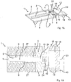
Das Luftverteilungsmodul für eine Klimatisierungseinrichtung eines Fahrzeugsitzes, das in einer perspektivischen Ansicht in der
Ein solches Luftverteilungsmodul 1 ist besonders für eine Anordnung auf der B-Seite eines Sitzpolsters oder auf der B-Seite eines Rückenlehnenpolsters geeignet, d. h. auf derjenigen Seite des jeweiligen Polsters, die einer auf dem Sitz sitzenden Person abgewandt ist. Allerdings ist nicht ausgeschlossen, dass ein solches Luftverteilungsmodul 1 auch auf der der sitzenden Person zugewandten Seite des jeweiligen Sitz- oder Rückenlehnenpolsters angeordnet ist. In einem solchen Fall ist vorgesehen, dass der Luftverteilungsraum 2 nur eine geringe Breite im Vergleich zu dessen Länge aufweist, wie dies beispielsweise in der Ausführungsform der
Die Dicke der Einlage 3 zwischen deren Oberseite 4 und Unterseite 5 liegt bei 5 mm bis 30 mm, bevorzugter im Bereich von 10 mm bis 15 mm.The thickness of the
Der Luftverteilungsraum 2 ist vollständig frei belassen, das bedeutet, es sind in dem Luftverteilungsraum 2 keine Abstandsmaterialien eingesetzt, die in irgendeiner Weise die durch den Luftverteilungsraum 2 hindurch geführte Luftströmung behindern oder beeinträchtigen könnten. Von dieser Maßgabe sind solche Teile ausgenommen, die sich an die Seitenwände 9 der Einlage 3, die den Luftverteilungsraum 2 begrenzen, und/oder an die Bodenfläche, die durch die Trägerschicht 6 gebildet ist, flächig anlegen.The
Die Einlage 3 kann aus einem Schaumstoffmaterial bestehen, vorzugsweise aus einem geschlossenporigen Schaumstoffmaterial, so dass die Einlage 3 im Wesentlichen luftundurchlässig ist, obwohl dies nicht unbedingt erforderlich ist, insbesondere dann nicht, wenn dieses Luftverteilungsmodul 1 in einer Ausnehmung eines Polsterkerns eingesetzt ist, derart, dass die Seitenkanten 7 der Einlage 3 innerhalb einer solchen Ausnehmung liegen. Die Einlage 3, oder Teile davon, könnten auch aus einem Faserverbundmaterial, aus einem Moosgummi, aus einem gepressten oder verdichteten Filz- oder filzartigem Material geformt werden, so dass die Einlage 3 zum einen im Wesentlichen formstabil ist und zum anderen eine solche Elastizität besitzt, dass sie sich einer in dem Sitzkissen vorhandenen Wölbung anpassen kann. Dies gilt besonders für den Fall, dass das Luftverteilungsmodul 1 in einer Ausnehmung eines Polsters eingesetzt wird, deren Bodenfläche eine leichte Krümmung oder Wölbung aufweist.The
Wie anhand der
In anderen Ausführungsformen, wie sie beispielsweise in den
Es sind auch Ausführungsformen des Luftverteilungsmoduls 1 vorgesehen, die sowohl eine Unterbrechung 10 im Bereich der Einlage 3 als auch eine Öffnung 11 in der Trägerschicht 6 für eine Luftzuführung aufweisen, wobei sowohl ein einzelner Lüfter mit einer entsprechenden Luftverteilungseinheit (Y-förmig) zur Verteilung von Luft zu der Unterbrechung 10 und zu der Öffnung 11 verwendet werden kann, als auch zwei Lüfter verwendet werden können.Embodiments of the
Wenn die Öffnung 11 in der Trägerschicht 6 in dem Bereich der Trägerschicht 6 positioniert wird, der sich unterhalb der Unterbrechung 10 in der Einlage 3 befindet, kann über einen einzigen Lüfter Luft sowohl über die Unterbrechung 10 als auch über die Öffnung 11 in der Trägerschicht 6 in den Luftverteilungsraum 2 strömen.If the
In den jeweiligen in den Figuren dargestellten Ausführungsformen des Luftverteilungsmoduls 1 besitzt die Trägerschicht 6 mindestens einen Verlängerungsabschnitt 12. Dieser Verlängerungsabschnitt 12 kann in den verschiedenen in den Figuren dargestellten Ausführungsformen in der Draufsicht, als Zuschnitt zusammen mit der Trägerschicht 6 betrachtet, sehr unterschiedliche Formen haben. Allerdings sind die jeweiligen Verlängerungsabschnitte 12 durch das gemeinsame Merkmal gekennzeichnet, dass damit eine Befestigung eines Lüfters, eines Gehäuses eines Lüfters und/oder einer Lüfterhalterung eines Lüfters an dem Luftverteilungsmodul erfolgt.In the respective embodiments of the
Es ist aber darauf hinzuweisen, dass der Verlängerungsabschnitt 12 weitere Funktionen übernehmen kann, indem Flächenabschnitte des Verlängerungsabschnitts 12 zum Aussteifen oder zum teilweisen Abdichten des Luftverteilungsraums 2 oder von Teilflächen der Einlage 3 dienen können. Für die Funktion, den Lüfter und/oder ein Gehäuse eines Lüfters und/oder die Lüfterhalterung eines Lüfters an das Luftverteilungsmodul anzubinden, werden zumindest Flächenteile des Verlängerungsabschnitts 12 um den Lüfter und/oder ein Gehäuse eines Lüfters und/oder die Lüfterhalterung eines Lüfters herum diese teilweise umschließend positioniert. Auch wird zumindest ein Teil solcher Flächenteile mit der Oberseite 4 der Einlage 3 verbunden oder so geführt, dass sie an der Unterseite 5 der Einlage 3, und dort vorzugsweise an der Außenseite der Trägerschicht 6, befestigt werden können.It should be noted, however, that the
Grundsätzlich werden neben dem Verlängerungsabschnitt 12 keine weiteren Befestigungsmittel benötigt oder vorgesehen, um den Lüfter an dem Luftverteilungsmodul 1 zu halten. Sollten allerdings zusätzliche Befestigungsteile zum Einsatz kommen, die in den Figuren nicht dargestellt sind, so übernimmt dennoch der Verlängerungsabschnitt 12 zu mindestens 50 % oder mindestens 75 % dieser Funktion, obwohl bevorzugt keine weiteren wesentlichen Befestigungsteile zum Einsatz kommen.In principle, no further fastening means are required or provided in addition to the
Unter dem Begriff des Verlängerungsabschnitts 12 fallen alle Flächenteile, die an die Trägerschicht 6 ansetzen, wobei die Trägerschicht 6 derjenige Bereich ist, der dem Teil der Einlage 3 zugeordnet ist, der den Luftverteilungsraum 2 umschließt. Demzufolge kann der Verlängerungsabschnitt 12 in mehrere Flächenteile unterteilt werden, die sich in verschiedene Richtungen erstrecken und beispielsweise in Form von einer Lasche, oder mehreren Laschen, ausgeführt sind.The term of the
Solche Laschen, mit dem Bezugszeichen 13 bezeichnet, sind in der Ausführungsform der
Der Verlängerungsabschnitt 12 ist an seiner Ober- und/oder Unterseite mit mindestens einer Klebeschicht 18 versehen, mit der der jeweilige Verlängerungsabschnitt 12 oder die jeweilige Lasche 13 als Teil des Verlängerungsabschnitts 12 mit dem der der Einlage 3 zugeordnete Teil des Luftverteilungsmoduls 1 verbunden werden kann, um die Lüftereinheit 14 an dem Luftverteilungsmoduls 1 zu befestigen.The
In den
Bei der Lüftereinheit 14, die in den
Um die Lüftereinheit 14 mit dem Luftverteilungsmodul 1, das in den
In diesen Schlitz 19 wird die Lüftereinheit 14 der
Wie anhand der Figuren zu erkennen ist, ist der Schlitz 19 und folglich entsprechend die formstabile Zunge 16 dort positioniert, wo an der Trägerschicht 6 der Verlängerungsabschnitt 12 ansetzt.As can be seen from the figures, the
Die Zunge 16 erstreckt sich entlang der Innenseite der Trägerschicht 6 in Richtung des Luftverteilungsraums 2, so dass sie in diesem Bereich zwischen der Trägerschicht 6 und der Unterseite 5 der Einlage 3 eingefügt ist. Zwischen dem Schlitz 19 und der Unterbrechung 10 der Einlage 3, über die die Luft in den Luftverteilungsraum 2 zugeführt wird, befindet sich auf der Innenseite der Trägerschicht 6 eine Klebefläche 20, mittels der die Zunge 16 an der Trägerschicht 6 verklebt wird. Die Position dieser Klebefläche 20 ist in
Nachdem die Zunge 16 vollständig von außen bzw. der Unterseite des Verlängerungsabschnitts 12 in den Schlitz 19 eingefügt ist, wird der Schlitz 19 so gedehnt, wie dies in
Nachdem das Lüftergehäuse 15 mit der Zunge 16 so positioniert ist, wie dies vorstehend beschrieben ist, wird der Verlängerungsabschnitt 12 auf die Oberseite 4 der Einlage 3 umgelegt und die jeweiligen inneren Laschen 13 an den gegenüber liegenden Seiten des Verlängerungsabschnitts 12 werden entweder an der Oberseite der Einlage 3 über die Klebeschichten 18 an den Enden der Laschen 13 verklebt oder sie werden um die Seitenflächen der Einlage 3 herum gelegt und an der Unterseite der Einlage 3 verklebt. Für den letzteren Fall ist die Einlage 3 an dem Ende, das im Bereich des Schlitzes 19 liegt, von einer geringeren Breite. Allerdings könnten diese Laschen 13 länger ausgeführt werden als dies in
Während der Verlängerungsabschnitt 12, wie er in den
Es ist auch vorgesehen, auf der jeweiligen Seite des Verlängerungsabschnitts 12 die eine der beiden dieser Seite zugeordneten Laschen 13 länger auszuführen als die andere Lasche 13, so dass dann die längere Lasche 13 (nicht in
Es sollte erwähnt werden, dass sich der Luftverteilungsraum 2 in der Einlage 3 in dem Bereich, in dem die Einlage 3 die Unterbrechung 10 für die Zuführung von Luft aufweist, in der Breite erweitert, insbesondere trichterförmig erweitert, werden kann, indem die Einlage 3 Verlängerungsteile in der Art von Fortsätzen 24 aufweist, um die Luft eines Lüfters, die im Bereich des Schlitzes 19 in das Luftverteilungsmodul 1 eintritt, auf den Querschnitt des Luftverteilungsraums 2 zu kanalisieren.It should be noted that the
Während sich der Luftverteilungsraum 2 an seinem offenen Ende durch die Fortsätze 24 trichterförmig erweitert, kann sich das offene Ende des Luftverteilungsraums 2 auch trichterförmig zu dem Schlitz 19 hin verengen, wie dies beispielsweise die Ausführungsform der
Es ist ausdrücklich darauf hinzuweisen, dass in der nachfolgenden Beschreibung der verschiedenen Ausführungsbeispiele, wie sie in den
Auch ist darauf hinzuweisen, dass Strömungsrichtungen, soweit sie erwähnt sind, auch umgekehrt werden können, so dass beispielsweise ein Lüfter oder eine Lüftereinheit, die Luft in den Luftverteilungsraum zuführt, auch Luft aus dem Luftverteilungsraum absaugen könnte.It should also be pointed out that flow directions, as far as they are mentioned, can also be reversed, so that, for example, a fan or a fan unit which supplies air into the air distribution space could also suck air out of the air distribution space.
Die
In den Ausführungsformen der
Es kann auch zweckmäßig sein, eine Lüftereinheit einzusetzen, bei der die Luftaustrittsöffnung direkt an die Unterbrechung 10 der Einlage 3 angesetzt wird und der Verlängerungsabschnitt 12, und gegebenenfalls dessen Laschenabschnitte 13, um den Lüfter bzw. dessen Lüftergehäuse bzw. einer Lüfterhalterung herumgelegt wird, um so die entsprechende Einheit, die Luft in den Luftverteilungsraum 2 zuführt, mit dem Luftverteilungsmodul 1 zu verbinden. In einem solchen Fall ist der Schlitz 19 in dem Übergangsbereich zwischen Trägerschicht 6 und Verlängerungsabschnitt 12 nicht erforderlich.It may also be expedient to use a fan unit, in which the air outlet opening is attached directly to the
Eine modifizierte Form des Luftverteilungsmodul 1, wie es in
Das Luftverteilungsmodul 1, wie es in
In den verschiedenen Ausführungsformen, die in den Figuren gezeigt sind, sind auf der Oberseite 4 der Einlage 3 Klebebereiche 27 vorhanden, die in bestimmten Anwendungsfällen, dazu dienen, das Luftverteilungsmodul 1 an einer Fläche des Sitzes, vorzugsweise an dem Polsterteil des Sitzes und dort in einer entsprechenden Ausnehmung des Sitzes, zu befestigen. Diese Klebebereiche 27 decken den überwiegenden Teil der Oberfläche 4 der Einlage 3 ab. Sie können aus einem doppelseitigen Klebeband, einer auf die Oberfläche 4 der Einlage 3 aufgetragenen Klebeschicht, die vorzugsweise aufgesprüht wird, und die vorzugsweise selbstklebend sind, bestehen.In the various embodiments shown in the figures, on the
Die
Die Ausführungsformen des Luftverteilungsmoduls 1, die in den
Die Öffnung 11 in der Trägerschicht 6 kann in einem geeigneten Bereich in Bezug auf den Luftverteilungsraum 2 angeordnet werden. Es ist jedoch bevorzugt, dass die Öffnung 11 an derjenigen Seite des Luftverteilungsraums 2 angeordnet ist, an der sich der Verlängerungsabschnitt 12 der Trägerschicht 6 anschließt.The
Für eine Luftzuführung wird ein Lüfter an der Unterseite des Luftverteilungsmoduls 1 so positioniert, dass sein Gehäuse zumindest im Bereich der radialen Auslassöffnung in den Luftverteilungsraum 2 hinein ragt, während der Teil des Gehäuses, über den die Luft angesaugt wird, auf der Unterseite der Trägerschicht positioniert ist. Der Verlängerungsabschnitt 12 wird zur Oberseite 4 der Einlage 3 umgelegt und dort an der Oberseite 4 befestigt, so dass der Lüfter abgedeckt ist, obwohl dies nicht unbedingt erforderlich ist. Zusätzlich kann der Verlängerungsabschnitt 12 nicht dargestellte Klebeflächen aufweisen, die sich mit der Oberseite 4 des Lüftergehäuses, die in den Luftverteilungsraum 2 vorsteht, verbinden, so dass der Verlängerungsabschnitt 12 auf sich selbst zurückgeklappt/gelegt werden kann.For an air supply, a fan on the bottom of the
Die
Das Luftverteilungsmodul 1, das in
Ein solches Versteifungselement 30 besitzt eine Grundplatte 31 mit Halteteilen 32, die an zwei gegenüberliegenden Seiten der Grundplatte 31 ansetzen. Diese Halteteile 32 besitzen zwei Schenkelabschnitte, wobei sich der eine erste Schenkelabschnitt 33 in Bezug auf die Ebene der Grundplatte 31 senkrecht nach oben erstreckt, während sich der andere zweite Schenkelabschnitt 34 an dem Ende des ersten Schenkelabschnitts 33 vertikal bzw. senkrecht zu dem ersten Schenkelabschnitt 33 nach außen erstreckt. Die Grundplatte 31 des Versteifungselements 30 ist so dargestellt, dass sie eine Struktur aufweist. Eine solche Struktur ist jedoch nicht erforderlich und dient im Wesentlichen nur zur besseren Darstellung. Bevorzugt ist eine glatte und ebene Platte.Such a
Als Besonderheit sind die Halteteile 32 anzusehen, insbesondere deren Form. Es ist zu erwähnen, dass die Halteteile 32, wie sie an die Ränder der Grundplatte 31 des Versteifungselements 30 angesetzt sind, voneinander getrennt sind, wie dies deutlicher in
Dieses Versteifungselement 30 dient dazu, den Innenraum, das bedeutet den Luftverteilungsraum 2 der Einlage 3, auszusteifen. Hierzu wird die Grundplatte 31 so in den Luftverteilungsraum 2 eingesetzt, dass sie auf der Innenseite der Trägerschicht 6, die den Luftverteilungsraum 2 auf dessen Unterseite begrenzt, flächig aufliegt. Dadurch wird eine stabile Bodenfläche in dem Luftverteilungsraum 2 erhalten, so dass sich der Luftverteilungsraum 2, wenn auf diesen äußere Kräfte, beispielsweise über das Sitzpolster, ausgeübt werden, nicht zusammendrückt oder in irgendeiner Weise kollabiert. Andererseits beeinträchtigt dieses Versteifungselement 30 nicht wesentlich den Querschnitt des Luftverteilungsraums, zumal die Grundplatte 31 des Versteifungselements 30 sehr dünn ausgeführt werden kann, vorzugsweise in einer Stärke von 0,5 mm bis 2 mm, bevorzugter von 0,5 mm bis 1,5 mm, und noch bevorzugter im Bereich von etwa 1 mm.This stiffening
Wenn das Versteifungselement 30 zumindest an den beiden gegenüber liegenden Seiten, aber auch dann, wenn die beiden anderen Seiten, mit den Halteteilen 32 versehen ist, wird die Grundplatte 31 zusätzlich am Rand der den Luftverteilungsraum 2 begrenzenden Einlage 3 abgestützt, indem sich die vertikal verlaufenden ersten Halteabschnitte 33 an den inneren Seitenwänden der Einlage 3 abstützen und sich die anderen, zweiten Schenkelabschnitte 34 auf die Oberseite 4 der Einlage 3 in deren Randbereich auflegen und/oder abstützen:
- Während in
den Figuren 9 und10 die Halteteile 32 einstückigmit der Grundplatte 31 des Versteifungselements 30 verbunden sind, können diese auch als separate Teile andie Grundplatte 31 angesetzt werden.
- While in the
Figures 9 and10 the holdingparts 32 are integrally connected to thebase plate 31 of the stiffeningelement 30, these can also be applied as separate parts to thebase plate 31.
Die Halteteile 32 sollten, wenn sie in der Form von zungenartigen Teilen unterteilt sind, wie dies in den Figuren dargestellt ist, im Wesentlichen fortlaufend aneinander gereiht und unabhängig voneinander bewegbar sein. Die Breite der zungenartigen Halteteile 32 sollte im Bereich von 3 mm bis 10 mm liegen, vorzugsweise im Bereich von etwa 5 mm, und benachbarte Halteteile 32 sollten voneinander durch einen Schlitz getrennt sein, der nicht breiter als maximal 1 mm beträgt, obwohl der Schlitz auch eine Breite von 0,5 mm bis 2 mm haben kann. Auch ist vorgesehen, dass in einer Ausführungsform des Versteifungselements 30, wie es in den
Das Versteifungselement 30 kann an dem Ende, an dem sich die Luftzufuhröffnung für die Luftzufuhr einer Lüftereinheit befindet, d.h. in dem Bereich, in dem auch die Einlage 3 unterbrochen ist, als rohrförmiger Kanal zur Aufnahme des Lüfters oder des Lüftergehäuses oder der Lüfterhalterung ausgebildet sein. Hierdurch wird, entsprechend der Zunge 16 der Lüftereinheit, die in
Falls ein Lüfter 14 Luft in den Luftverteilungsraum 2 über eine Öffnung 11 in der Trägerschicht 6 zuführen soll, wie dies vorstehend anhand der
Wie bereits erwähnt, wird das Versteifungselement 30 aus einem steifen Material mit einer definierten Biegeelastizität gebildet. Die Biegeelastizität soll gewährleisten, dass, unter Einwirkung von Kräften, die Kontur-Abmessungen des Luftverteilungsraums 2 nicht wesentlich verändert werden, aber dennoch eine geringe Wölbung der Grundplatte 31 möglich ist, so dass sich das Luftverteilungsmodul 1 insbesondere im Bereich dessen Luftverteilungsraums 2 einer geringen Verformung eines Sitzpolsters, in das das Luftverteilungsmodul 1 eingesetzt ist, oder sich daran anlegt, folgen kann, so dass es für einen Benutzer des Sitzes in keiner Weise spürbar ist.As already mentioned, the stiffening
Als Material für das Versteifungselement 30 sollte ein Kunststoff mit zumindest teilweise elastischen Eigenschaften verwendet werden. Die Materialdicke für das Versteifungselement 30 liegt im Bereich von 0,3 mm bis 10 mm, bevorzugt im Bereich von 0,5 mm bis 5 mm, besonders bevorzugt im Bereich von 1 mm bis 3 mm oder 1 mm bis 1,5 mm. In jedem Fall sollte die Dicke des Versteifungselements 30 gering gehalten werden.As the material for the
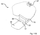
Die Lüftereinheit 14, wie sie in den
Bei dieser Lüftereinheit 14 handelt es sich um einen Lüfter, der die Luft axial über eine Lüfteröffnung 35 ansaugt und diese Luft radial über eine weitere Lüfteröffnung 36 im Bereich der formstabilen Zunge 16 abgibt. Das Lüftergehäuse besitzt auf einer Seite ein Klemm- oder Befestigungsteil 37, mit dem es beispielsweise an einer Sitzstruktur befestigt werden kann. Bevorzugt wird das Lüftergehäuse zumindest teilweise in einen Polsterkern auf der B-Seite eines Sitzpolsters eingesetzt.This
Claims (15)
Applications Claiming Priority (1)
| Application Number | Priority Date | Filing Date | Title |
|---|---|---|---|
| DE202016002041.3U DE202016002041U1 (en) | 2016-04-04 | 2016-04-04 | Air conditioning device for a vehicle seat |
Publications (2)
| Publication Number | Publication Date |
|---|---|
| EP3228494A1 true EP3228494A1 (en) | 2017-10-11 |
| EP3228494B1 EP3228494B1 (en) | 2019-01-02 |
Family
ID=58358339
Family Applications (1)
| Application Number | Title | Priority Date | Filing Date |
|---|---|---|---|
| EP17000429.5A Active EP3228494B1 (en) | 2016-04-04 | 2017-03-16 | Air conditioning unit for a vehicle seat |
Country Status (3)
| Country | Link |
|---|---|
| US (1) | US10960795B2 (en) |
| EP (1) | EP3228494B1 (en) |
| DE (1) | DE202016002041U1 (en) |
Families Citing this family (7)
| Publication number | Priority date | Publication date | Assignee | Title |
|---|---|---|---|---|
| DE202013006135U1 (en) * | 2013-07-09 | 2013-07-25 | I.G. Bauerhin Gmbh | Air conditioning device for a vehicle seat |
| US10589647B2 (en) | 2013-12-05 | 2020-03-17 | Gentherm Incorporated | Systems and methods for climate controlled seats |
| CN106028874B (en) | 2014-02-14 | 2020-01-31 | 金瑟姆股份公司 | Conductive convection climate control seat |
| US11033058B2 (en) | 2014-11-14 | 2021-06-15 | Gentherm Incorporated | Heating and cooling technologies |
| US11857004B2 (en) | 2014-11-14 | 2024-01-02 | Gentherm Incorporated | Heating and cooling technologies |
| US11639816B2 (en) | 2014-11-14 | 2023-05-02 | Gentherm Incorporated | Heating and cooling technologies including temperature regulating pad wrap and technologies with liquid system |
| RU2736850C1 (en) * | 2019-11-19 | 2020-11-20 | Петр Анатольевич Лукашев | Vehicle seat ventilation device and ventilation method |
Citations (3)
| Publication number | Priority date | Publication date | Assignee | Title |
|---|---|---|---|---|
| US20070277313A1 (en) | 2006-05-31 | 2007-12-06 | John Terech | Structure based fluid distribution system |
| DE202013006136U1 (en) * | 2013-07-09 | 2013-07-30 | I.G. Bauerhin Gmbh | Arrangement of a cushion core with air conditioning device |
| EP2826663A1 (en) | 2013-07-09 | 2015-01-21 | I.G. Bauerhin GmbH | Air conditioning unit for a vehicle seat |
Family Cites Families (4)
| Publication number | Priority date | Publication date | Assignee | Title |
|---|---|---|---|---|
| US5692952A (en) * | 1996-02-01 | 1997-12-02 | Chih-Hung; Ling | Air-conditioned seat cushion |
| CN101115642B (en) * | 2005-02-07 | 2011-01-05 | L&P产权管理公司 | Heat, cool, and ventilate system for automotive applications |
| US7478869B2 (en) * | 2005-08-19 | 2009-01-20 | W.E.T. Automotive Systems, Ag | Automotive vehicle seat insert |
| US9061617B2 (en) * | 2011-05-17 | 2015-06-23 | Igb Automotive Ltd. | Thin ventilated seat for a vehicle and items of furniture |
-
2016
- 2016-04-04 DE DE202016002041.3U patent/DE202016002041U1/en not_active Expired - Lifetime
-
2017
- 2017-03-08 US US15/453,007 patent/US10960795B2/en active Active
- 2017-03-16 EP EP17000429.5A patent/EP3228494B1/en active Active
Patent Citations (3)
| Publication number | Priority date | Publication date | Assignee | Title |
|---|---|---|---|---|
| US20070277313A1 (en) | 2006-05-31 | 2007-12-06 | John Terech | Structure based fluid distribution system |
| DE202013006136U1 (en) * | 2013-07-09 | 2013-07-30 | I.G. Bauerhin Gmbh | Arrangement of a cushion core with air conditioning device |
| EP2826663A1 (en) | 2013-07-09 | 2015-01-21 | I.G. Bauerhin GmbH | Air conditioning unit for a vehicle seat |
Also Published As
| Publication number | Publication date |
|---|---|
| EP3228494B1 (en) | 2019-01-02 |
| DE202016002041U1 (en) | 2017-07-05 |
| US10960795B2 (en) | 2021-03-30 |
| US20170282764A1 (en) | 2017-10-05 |
Similar Documents
| Publication | Publication Date | Title |
|---|---|---|
| EP3228494B1 (en) | Air conditioning unit for a vehicle seat | |
| EP2826663B1 (en) | Air conditioning unit for a vehicle seat | |
| EP3293042B1 (en) | Vehicle seat | |
| EP1813471B1 (en) | Insert for climatised seat, assembly with at least two inserts, vehicle seat showing such an insert or assembly | |
| EP2059412B1 (en) | Air-conditioned seat | |
| DE102010029377B4 (en) | Fastening tape assembly and foam body containing them | |
| DE102006023129B4 (en) | Seat arrangement with an air chamber member | |
| DE202014005998U1 (en) | Air conditioning device for conditioning the backrest or the seat surface of a vehicle seat | |
| DE202014009326U1 (en) | Vehicle seat with an air conditioning device | |
| DE102012005739A1 (en) | Plastic component and method for producing a plastic component | |
| EP2627213A2 (en) | Adhesive mat and device for attaching objects | |
| DE102005039779A1 (en) | Air distribution device for a unit in the passenger compartment | |
| EP2630310B1 (en) | Frame profile system | |
| DE202006020287U1 (en) | Filter element with deep-drawn frame | |
| DE102009042588B4 (en) | Filter system with at least one frame element on its longitudinal edge | |
| DE202009017383U1 (en) | Assembly for the air conditioning of at least part of a seat | |
| DE102011114933B9 (en) | "Seat frame for a vehicle seat" | |
| DE102010050772B4 (en) | Assembly for the air conditioning of at least part of a seat | |
| DE102014224549A1 (en) | Plate-shaped filter element and filter device | |
| DE102016003833A1 (en) | Air conditioning device for a vehicle seat | |
| EP2110110B1 (en) | Diaper fastener, nappy, semi-finished strips, application method for a diaper fastener and production method for a semi-finished strip | |
| DE202013006136U1 (en) | Arrangement of a cushion core with air conditioning device | |
| DE102016010808B4 (en) | vehicle seat | |
| DE102017206751A1 (en) | VEHICLE SEAT SYSTEM | |
| DE10338525A1 (en) | Vehicle seat with ventilation layer, includes depressions formed by plastic deformation of spirally-formed underbody in which fasteners to lower layer are fitted |
Legal Events
| Date | Code | Title | Description |
|---|---|---|---|
| STAA | Information on the status of an ep patent application or granted ep patent |
Free format text: STATUS: UNKNOWN |
|
| PUAI | Public reference made under article 153(3) epc to a published international application that has entered the european phase |
Free format text: ORIGINAL CODE: 0009012 |
|
| STAA | Information on the status of an ep patent application or granted ep patent |
Free format text: STATUS: THE APPLICATION HAS BEEN PUBLISHED |
|
| AK | Designated contracting states |
Kind code of ref document: A1 Designated state(s): AL AT BE BG CH CY CZ DE DK EE ES FI FR GB GR HR HU IE IS IT LI LT LU LV MC MK MT NL NO PL PT RO RS SE SI SK SM TR |
|
| AX | Request for extension of the european patent |
Extension state: BA ME |
|
| STAA | Information on the status of an ep patent application or granted ep patent |
Free format text: STATUS: REQUEST FOR EXAMINATION WAS MADE |
|
| 17P | Request for examination filed |
Effective date: 20180301 |
|
| RBV | Designated contracting states (corrected) |
Designated state(s): AL AT BE BG CH CY CZ DE DK EE ES FI FR GB GR HR HU IE IS IT LI LT LU LV MC MK MT NL NO PL PT RO RS SE SI SK SM TR |
|
| GRAP | Despatch of communication of intention to grant a patent |
Free format text: ORIGINAL CODE: EPIDOSNIGR1 |
|
| STAA | Information on the status of an ep patent application or granted ep patent |
Free format text: STATUS: GRANT OF PATENT IS INTENDED |
|
| INTG | Intention to grant announced |
Effective date: 20180724 |
|
| GRAS | Grant fee paid |
Free format text: ORIGINAL CODE: EPIDOSNIGR3 |
|
| GRAA | (expected) grant |
Free format text: ORIGINAL CODE: 0009210 |
|
| STAA | Information on the status of an ep patent application or granted ep patent |
Free format text: STATUS: THE PATENT HAS BEEN GRANTED |
|
| AK | Designated contracting states |
Kind code of ref document: B1 Designated state(s): AL AT BE BG CH CY CZ DE DK EE ES FI FR GB GR HR HU IE IS IT LI LT LU LV MC MK MT NL NO PL PT RO RS SE SI SK SM TR |
|
| REG | Reference to a national code |
Ref country code: GB Ref legal event code: FG4D Free format text: NOT ENGLISH |
|
| REG | Reference to a national code |
Ref country code: CH Ref legal event code: EP Ref country code: AT Ref legal event code: REF Ref document number: 1083923 Country of ref document: AT Kind code of ref document: T Effective date: 20190115 |
|
| REG | Reference to a national code |
Ref country code: IE Ref legal event code: FG4D Free format text: LANGUAGE OF EP DOCUMENT: GERMAN |
|
| REG | Reference to a national code |
Ref country code: DE Ref legal event code: R096 Ref document number: 502017000566 Country of ref document: DE |
|
| REG | Reference to a national code |
Ref country code: SE Ref legal event code: TRGR |
|
| REG | Reference to a national code |
Ref country code: NL Ref legal event code: MP Effective date: 20190102 |
|
| REG | Reference to a national code |
Ref country code: LT Ref legal event code: MG4D |
|
| PG25 | Lapsed in a contracting state [announced via postgrant information from national office to epo] |
Ref country code: NL Free format text: LAPSE BECAUSE OF FAILURE TO SUBMIT A TRANSLATION OF THE DESCRIPTION OR TO PAY THE FEE WITHIN THE PRESCRIBED TIME-LIMIT Effective date: 20190102 |
|
| PG25 | Lapsed in a contracting state [announced via postgrant information from national office to epo] |
Ref country code: NO Free format text: LAPSE BECAUSE OF FAILURE TO SUBMIT A TRANSLATION OF THE DESCRIPTION OR TO PAY THE FEE WITHIN THE PRESCRIBED TIME-LIMIT Effective date: 20190402 Ref country code: ES Free format text: LAPSE BECAUSE OF FAILURE TO SUBMIT A TRANSLATION OF THE DESCRIPTION OR TO PAY THE FEE WITHIN THE PRESCRIBED TIME-LIMIT Effective date: 20190102 Ref country code: LT Free format text: LAPSE BECAUSE OF FAILURE TO SUBMIT A TRANSLATION OF THE DESCRIPTION OR TO PAY THE FEE WITHIN THE PRESCRIBED TIME-LIMIT Effective date: 20190102 Ref country code: PL Free format text: LAPSE BECAUSE OF FAILURE TO SUBMIT A TRANSLATION OF THE DESCRIPTION OR TO PAY THE FEE WITHIN THE PRESCRIBED TIME-LIMIT Effective date: 20190102 Ref country code: PT Free format text: LAPSE BECAUSE OF FAILURE TO SUBMIT A TRANSLATION OF THE DESCRIPTION OR TO PAY THE FEE WITHIN THE PRESCRIBED TIME-LIMIT Effective date: 20190502 Ref country code: FI Free format text: LAPSE BECAUSE OF FAILURE TO SUBMIT A TRANSLATION OF THE DESCRIPTION OR TO PAY THE FEE WITHIN THE PRESCRIBED TIME-LIMIT Effective date: 20190102 |
|
| PG25 | Lapsed in a contracting state [announced via postgrant information from national office to epo] |
Ref country code: HR Free format text: LAPSE BECAUSE OF FAILURE TO SUBMIT A TRANSLATION OF THE DESCRIPTION OR TO PAY THE FEE WITHIN THE PRESCRIBED TIME-LIMIT Effective date: 20190102 Ref country code: LV Free format text: LAPSE BECAUSE OF FAILURE TO SUBMIT A TRANSLATION OF THE DESCRIPTION OR TO PAY THE FEE WITHIN THE PRESCRIBED TIME-LIMIT Effective date: 20190102 Ref country code: BG Free format text: LAPSE BECAUSE OF FAILURE TO SUBMIT A TRANSLATION OF THE DESCRIPTION OR TO PAY THE FEE WITHIN THE PRESCRIBED TIME-LIMIT Effective date: 20190402 Ref country code: RS Free format text: LAPSE BECAUSE OF FAILURE TO SUBMIT A TRANSLATION OF THE DESCRIPTION OR TO PAY THE FEE WITHIN THE PRESCRIBED TIME-LIMIT Effective date: 20190102 Ref country code: IS Free format text: LAPSE BECAUSE OF FAILURE TO SUBMIT A TRANSLATION OF THE DESCRIPTION OR TO PAY THE FEE WITHIN THE PRESCRIBED TIME-LIMIT Effective date: 20190502 Ref country code: GR Free format text: LAPSE BECAUSE OF FAILURE TO SUBMIT A TRANSLATION OF THE DESCRIPTION OR TO PAY THE FEE WITHIN THE PRESCRIBED TIME-LIMIT Effective date: 20190403 |
|
| REG | Reference to a national code |
Ref country code: DE Ref legal event code: R097 Ref document number: 502017000566 Country of ref document: DE |
|
| PG25 | Lapsed in a contracting state [announced via postgrant information from national office to epo] |
Ref country code: EE Free format text: LAPSE BECAUSE OF FAILURE TO SUBMIT A TRANSLATION OF THE DESCRIPTION OR TO PAY THE FEE WITHIN THE PRESCRIBED TIME-LIMIT Effective date: 20190102 Ref country code: DK Free format text: LAPSE BECAUSE OF FAILURE TO SUBMIT A TRANSLATION OF THE DESCRIPTION OR TO PAY THE FEE WITHIN THE PRESCRIBED TIME-LIMIT Effective date: 20190102 Ref country code: MC Free format text: LAPSE BECAUSE OF FAILURE TO SUBMIT A TRANSLATION OF THE DESCRIPTION OR TO PAY THE FEE WITHIN THE PRESCRIBED TIME-LIMIT Effective date: 20190102 Ref country code: AL Free format text: LAPSE BECAUSE OF FAILURE TO SUBMIT A TRANSLATION OF THE DESCRIPTION OR TO PAY THE FEE WITHIN THE PRESCRIBED TIME-LIMIT Effective date: 20190102 Ref country code: RO Free format text: LAPSE BECAUSE OF FAILURE TO SUBMIT A TRANSLATION OF THE DESCRIPTION OR TO PAY THE FEE WITHIN THE PRESCRIBED TIME-LIMIT Effective date: 20190102 Ref country code: IT Free format text: LAPSE BECAUSE OF FAILURE TO SUBMIT A TRANSLATION OF THE DESCRIPTION OR TO PAY THE FEE WITHIN THE PRESCRIBED TIME-LIMIT Effective date: 20190102 |
|
| PLBE | No opposition filed within time limit |
Free format text: ORIGINAL CODE: 0009261 |
|
| STAA | Information on the status of an ep patent application or granted ep patent |
Free format text: STATUS: NO OPPOSITION FILED WITHIN TIME LIMIT |
|
| PG25 | Lapsed in a contracting state [announced via postgrant information from national office to epo] |
Ref country code: SM Free format text: LAPSE BECAUSE OF FAILURE TO SUBMIT A TRANSLATION OF THE DESCRIPTION OR TO PAY THE FEE WITHIN THE PRESCRIBED TIME-LIMIT Effective date: 20190102 Ref country code: LU Free format text: LAPSE BECAUSE OF NON-PAYMENT OF DUE FEES Effective date: 20190316 |
|
| 26N | No opposition filed |
Effective date: 20191003 |
|
| REG | Reference to a national code |
Ref country code: BE Ref legal event code: MM Effective date: 20190331 |
|
| PG25 | Lapsed in a contracting state [announced via postgrant information from national office to epo] |
Ref country code: IE Free format text: LAPSE BECAUSE OF NON-PAYMENT OF DUE FEES Effective date: 20190316 |
|
| PG25 | Lapsed in a contracting state [announced via postgrant information from national office to epo] |
Ref country code: BE Free format text: LAPSE BECAUSE OF NON-PAYMENT OF DUE FEES Effective date: 20190331 Ref country code: SI Free format text: LAPSE BECAUSE OF FAILURE TO SUBMIT A TRANSLATION OF THE DESCRIPTION OR TO PAY THE FEE WITHIN THE PRESCRIBED TIME-LIMIT Effective date: 20190102 |
|
| PG25 | Lapsed in a contracting state [announced via postgrant information from national office to epo] |
Ref country code: TR Free format text: LAPSE BECAUSE OF FAILURE TO SUBMIT A TRANSLATION OF THE DESCRIPTION OR TO PAY THE FEE WITHIN THE PRESCRIBED TIME-LIMIT Effective date: 20190102 |
|
| PG25 | Lapsed in a contracting state [announced via postgrant information from national office to epo] |
Ref country code: MT Free format text: LAPSE BECAUSE OF FAILURE TO SUBMIT A TRANSLATION OF THE DESCRIPTION OR TO PAY THE FEE WITHIN THE PRESCRIBED TIME-LIMIT Effective date: 20190102 |
|
| REG | Reference to a national code |
Ref country code: CH Ref legal event code: PL |
|
| PG25 | Lapsed in a contracting state [announced via postgrant information from national office to epo] |
Ref country code: LI Free format text: LAPSE BECAUSE OF NON-PAYMENT OF DUE FEES Effective date: 20200331 Ref country code: CH Free format text: LAPSE BECAUSE OF NON-PAYMENT OF DUE FEES Effective date: 20200331 |
|
| PG25 | Lapsed in a contracting state [announced via postgrant information from national office to epo] |
Ref country code: CY Free format text: LAPSE BECAUSE OF FAILURE TO SUBMIT A TRANSLATION OF THE DESCRIPTION OR TO PAY THE FEE WITHIN THE PRESCRIBED TIME-LIMIT Effective date: 20190102 |
|
| PGFP | Annual fee paid to national office [announced via postgrant information from national office to epo] |
Ref country code: SE Payment date: 20210319 Year of fee payment: 5 |
|
| PG25 | Lapsed in a contracting state [announced via postgrant information from national office to epo] |
Ref country code: HU Free format text: LAPSE BECAUSE OF FAILURE TO SUBMIT A TRANSLATION OF THE DESCRIPTION OR TO PAY THE FEE WITHIN THE PRESCRIBED TIME-LIMIT; INVALID AB INITIO Effective date: 20170316 |
|
| PG25 | Lapsed in a contracting state [announced via postgrant information from national office to epo] |
Ref country code: MK Free format text: LAPSE BECAUSE OF FAILURE TO SUBMIT A TRANSLATION OF THE DESCRIPTION OR TO PAY THE FEE WITHIN THE PRESCRIBED TIME-LIMIT Effective date: 20190102 |
|
| PG25 | Lapsed in a contracting state [announced via postgrant information from national office to epo] |
Ref country code: SE Free format text: LAPSE BECAUSE OF NON-PAYMENT OF DUE FEES Effective date: 20220317 |
|
| PGFP | Annual fee paid to national office [announced via postgrant information from national office to epo] |
Ref country code: FR Payment date: 20230324 Year of fee payment: 7 |
|
| REG | Reference to a national code |
Ref country code: AT Ref legal event code: MM01 Ref document number: 1083923 Country of ref document: AT Kind code of ref document: T Effective date: 20220316 |
|
| PGFP | Annual fee paid to national office [announced via postgrant information from national office to epo] |
Ref country code: SK Payment date: 20230307 Year of fee payment: 7 Ref country code: GB Payment date: 20230322 Year of fee payment: 7 Ref country code: DE Payment date: 20230321 Year of fee payment: 7 |
|
| PG25 | Lapsed in a contracting state [announced via postgrant information from national office to epo] |
Ref country code: AT Free format text: LAPSE BECAUSE OF NON-PAYMENT OF DUE FEES Effective date: 20220316 |
|
| PGFP | Annual fee paid to national office [announced via postgrant information from national office to epo] |
Ref country code: CZ Payment date: 20230628 Year of fee payment: 8 |
|
| PGFP | Annual fee paid to national office [announced via postgrant information from national office to epo] |
Ref country code: SK Payment date: 20230622 Year of fee payment: 7 |