EP3225261A1 - Reduced-pressure, abdominal treatment systems and methods - Google Patents
Reduced-pressure, abdominal treatment systems and methods Download PDFInfo
- Publication number
- EP3225261A1 EP3225261A1 EP17157217.5A EP17157217A EP3225261A1 EP 3225261 A1 EP3225261 A1 EP 3225261A1 EP 17157217 A EP17157217 A EP 17157217A EP 3225261 A1 EP3225261 A1 EP 3225261A1
- Authority
- EP
- European Patent Office
- Prior art keywords
- reduced
- pressure
- attachment
- members
- contracting
- Prior art date
- Legal status (The legal status is an assumption and is not a legal conclusion. Google has not performed a legal analysis and makes no representation as to the accuracy of the status listed.)
- Granted
Links
- 230000003187 abdominal effect Effects 0.000 title claims abstract description 56
- 238000000034 method Methods 0.000 title abstract description 23
- 210000002615 epidermis Anatomy 0.000 claims abstract description 61
- 210000003195 fascia Anatomy 0.000 claims abstract description 48
- 239000011159 matrix material Substances 0.000 claims description 65
- 238000007789 sealing Methods 0.000 claims description 64
- 239000000463 material Substances 0.000 claims description 41
- 230000002093 peripheral effect Effects 0.000 claims description 40
- 239000000853 adhesive Substances 0.000 claims description 29
- 230000001070 adhesive effect Effects 0.000 claims description 29
- 230000008878 coupling Effects 0.000 claims description 23
- 238000010168 coupling process Methods 0.000 claims description 23
- 238000005859 coupling reaction Methods 0.000 claims description 23
- KRTSDMXIXPKRQR-AATRIKPKSA-N monocrotophos Chemical compound CNC(=O)\C=C(/C)OP(=O)(OC)OC KRTSDMXIXPKRQR-AATRIKPKSA-N 0.000 claims 2
- 206010052428 Wound Diseases 0.000 description 161
- 208000027418 Wounds and injury Diseases 0.000 description 159
- 210000000683 abdominal cavity Anatomy 0.000 description 60
- 210000001519 tissue Anatomy 0.000 description 60
- 239000012530 fluid Substances 0.000 description 57
- 230000001464 adherent effect Effects 0.000 description 40
- 210000004027 cell Anatomy 0.000 description 40
- 238000005538 encapsulation Methods 0.000 description 25
- 238000013459 approach Methods 0.000 description 10
- 238000004891 communication Methods 0.000 description 9
- 239000006260 foam Substances 0.000 description 9
- 238000003466 welding Methods 0.000 description 8
- 239000012790 adhesive layer Substances 0.000 description 7
- 210000002421 cell wall Anatomy 0.000 description 7
- 230000000007 visual effect Effects 0.000 description 7
- 210000001015 abdomen Anatomy 0.000 description 6
- -1 dead tissue Proteins 0.000 description 5
- 239000010410 layer Substances 0.000 description 5
- 229920002803 thermoplastic polyurethane Polymers 0.000 description 5
- 230000008901 benefit Effects 0.000 description 4
- 238000003780 insertion Methods 0.000 description 4
- 230000037431 insertion Effects 0.000 description 4
- 239000007788 liquid Substances 0.000 description 4
- 229920001296 polysiloxane Polymers 0.000 description 4
- 229920006264 polyurethane film Polymers 0.000 description 4
- 206010003445 Ascites Diseases 0.000 description 3
- 239000004568 cement Substances 0.000 description 3
- 238000001514 detection method Methods 0.000 description 3
- 239000003814 drug Substances 0.000 description 3
- 210000000416 exudates and transudate Anatomy 0.000 description 3
- 230000035876 healing Effects 0.000 description 3
- 238000004519 manufacturing process Methods 0.000 description 3
- 239000000126 substance Substances 0.000 description 3
- 238000002560 therapeutic procedure Methods 0.000 description 3
- 206010058808 Abdominal compartment syndrome Diseases 0.000 description 2
- 241000894006 Bacteria Species 0.000 description 2
- 206010063560 Excessive granulation tissue Diseases 0.000 description 2
- 208000002623 Intra-Abdominal Hypertension Diseases 0.000 description 2
- 206010030113 Oedema Diseases 0.000 description 2
- 239000004743 Polypropylene Substances 0.000 description 2
- 239000000560 biocompatible material Substances 0.000 description 2
- 239000008280 blood Substances 0.000 description 2
- 210000004369 blood Anatomy 0.000 description 2
- 230000008602 contraction Effects 0.000 description 2
- 238000005520 cutting process Methods 0.000 description 2
- 229940079593 drug Drugs 0.000 description 2
- 229920001971 elastomer Polymers 0.000 description 2
- 239000000806 elastomer Substances 0.000 description 2
- 210000001126 granulation tissue Anatomy 0.000 description 2
- 230000002209 hydrophobic effect Effects 0.000 description 2
- 208000015181 infectious disease Diseases 0.000 description 2
- 208000014674 injury Diseases 0.000 description 2
- 230000002262 irrigation Effects 0.000 description 2
- 238000003973 irrigation Methods 0.000 description 2
- 210000004185 liver Anatomy 0.000 description 2
- 238000012544 monitoring process Methods 0.000 description 2
- 210000003205 muscle Anatomy 0.000 description 2
- 230000037361 pathway Effects 0.000 description 2
- 229920003023 plastic Polymers 0.000 description 2
- 239000004033 plastic Substances 0.000 description 2
- 229920001155 polypropylene Polymers 0.000 description 2
- 210000003491 skin Anatomy 0.000 description 2
- 238000001356 surgical procedure Methods 0.000 description 2
- 230000008733 trauma Effects 0.000 description 2
- 102000009123 Fibrin Human genes 0.000 description 1
- 108010073385 Fibrin Proteins 0.000 description 1
- BWGVNKXGVNDBDI-UHFFFAOYSA-N Fibrin monomer Chemical compound CNC(=O)CNC(=O)CN BWGVNKXGVNDBDI-UHFFFAOYSA-N 0.000 description 1
- 206010019909 Hernia Diseases 0.000 description 1
- 229920001247 Reticulated foam Polymers 0.000 description 1
- NIXOWILDQLNWCW-UHFFFAOYSA-N acrylic acid group Chemical group C(C=C)(=O)O NIXOWILDQLNWCW-UHFFFAOYSA-N 0.000 description 1
- 230000009471 action Effects 0.000 description 1
- 239000002313 adhesive film Substances 0.000 description 1
- 230000004075 alteration Effects 0.000 description 1
- 230000000844 anti-bacterial effect Effects 0.000 description 1
- 229940088710 antibiotic agent Drugs 0.000 description 1
- 230000004888 barrier function Effects 0.000 description 1
- 230000001413 cellular effect Effects 0.000 description 1
- 230000008859 change Effects 0.000 description 1
- 150000001875 compounds Chemical class 0.000 description 1
- 238000010586 diagram Methods 0.000 description 1
- 238000009826 distribution Methods 0.000 description 1
- 229950003499 fibrin Drugs 0.000 description 1
- 238000009472 formulation Methods 0.000 description 1
- 230000004927 fusion Effects 0.000 description 1
- 239000000499 gel Substances 0.000 description 1
- 239000003102 growth factor Substances 0.000 description 1
- 239000000017 hydrogel Substances 0.000 description 1
- 230000002706 hydrostatic effect Effects 0.000 description 1
- 238000009434 installation Methods 0.000 description 1
- 230000001788 irregular Effects 0.000 description 1
- 238000007726 management method Methods 0.000 description 1
- 238000005259 measurement Methods 0.000 description 1
- 238000002483 medication Methods 0.000 description 1
- 239000000203 mixture Substances 0.000 description 1
- 230000017074 necrotic cell death Effects 0.000 description 1
- 238000009581 negative-pressure wound therapy Methods 0.000 description 1
- 230000000737 periodic effect Effects 0.000 description 1
- 210000003200 peritoneal cavity Anatomy 0.000 description 1
- 206010034674 peritonitis Diseases 0.000 description 1
- 230000035699 permeability Effects 0.000 description 1
- 229920002635 polyurethane Polymers 0.000 description 1
- 239000004814 polyurethane Substances 0.000 description 1
- 239000011148 porous material Substances 0.000 description 1
- 238000005096 rolling process Methods 0.000 description 1
- 239000003566 sealing material Substances 0.000 description 1
- 229920002379 silicone rubber Polymers 0.000 description 1
- 239000004945 silicone rubber Substances 0.000 description 1
- 239000007787 solid Substances 0.000 description 1
- 238000005728 strengthening Methods 0.000 description 1
- 238000006467 substitution reaction Methods 0.000 description 1
- 230000000699 topical effect Effects 0.000 description 1
- 239000003053 toxin Substances 0.000 description 1
- 231100000765 toxin Toxicity 0.000 description 1
- 108700012359 toxins Proteins 0.000 description 1
- 210000001835 viscera Anatomy 0.000 description 1
Images


Classifications
-
- A—HUMAN NECESSITIES
- A61—MEDICAL OR VETERINARY SCIENCE; HYGIENE
- A61M—DEVICES FOR INTRODUCING MEDIA INTO, OR ONTO, THE BODY; DEVICES FOR TRANSDUCING BODY MEDIA OR FOR TAKING MEDIA FROM THE BODY; DEVICES FOR PRODUCING OR ENDING SLEEP OR STUPOR
- A61M1/00—Suction or pumping devices for medical purposes; Devices for carrying-off, for treatment of, or for carrying-over, body-liquids; Drainage systems
- A61M1/90—Negative pressure wound therapy devices, i.e. devices for applying suction to a wound to promote healing, e.g. including a vacuum dressing
- A61M1/96—Suction control thereof
- A61M1/964—Suction control thereof having venting means on or near the dressing
-
- A—HUMAN NECESSITIES
- A61—MEDICAL OR VETERINARY SCIENCE; HYGIENE
- A61B—DIAGNOSIS; SURGERY; IDENTIFICATION
- A61B17/00—Surgical instruments, devices or methods, e.g. tourniquets
- A61B17/0057—Implements for plugging an opening in the wall of a hollow or tubular organ, e.g. for sealing a vessel puncture or closing a cardiac septal defect
-
- A—HUMAN NECESSITIES
- A61—MEDICAL OR VETERINARY SCIENCE; HYGIENE
- A61F—FILTERS IMPLANTABLE INTO BLOOD VESSELS; PROSTHESES; DEVICES PROVIDING PATENCY TO, OR PREVENTING COLLAPSING OF, TUBULAR STRUCTURES OF THE BODY, e.g. STENTS; ORTHOPAEDIC, NURSING OR CONTRACEPTIVE DEVICES; FOMENTATION; TREATMENT OR PROTECTION OF EYES OR EARS; BANDAGES, DRESSINGS OR ABSORBENT PADS; FIRST-AID KITS
- A61F13/00—Bandages or dressings; Absorbent pads
- A61F13/00987—Apparatus or processes for manufacturing non-adhesive dressings or bandages
-
- A61F13/01025—
-
- A61F13/01034—
-
- A—HUMAN NECESSITIES
- A61—MEDICAL OR VETERINARY SCIENCE; HYGIENE
- A61F—FILTERS IMPLANTABLE INTO BLOOD VESSELS; PROSTHESES; DEVICES PROVIDING PATENCY TO, OR PREVENTING COLLAPSING OF, TUBULAR STRUCTURES OF THE BODY, e.g. STENTS; ORTHOPAEDIC, NURSING OR CONTRACEPTIVE DEVICES; FOMENTATION; TREATMENT OR PROTECTION OF EYES OR EARS; BANDAGES, DRESSINGS OR ABSORBENT PADS; FIRST-AID KITS
- A61F13/00—Bandages or dressings; Absorbent pads
- A61F13/02—Adhesive plasters or dressings
-
- A61F13/05—
-
- A—HUMAN NECESSITIES
- A61—MEDICAL OR VETERINARY SCIENCE; HYGIENE
- A61M—DEVICES FOR INTRODUCING MEDIA INTO, OR ONTO, THE BODY; DEVICES FOR TRANSDUCING BODY MEDIA OR FOR TAKING MEDIA FROM THE BODY; DEVICES FOR PRODUCING OR ENDING SLEEP OR STUPOR
- A61M1/00—Suction or pumping devices for medical purposes; Devices for carrying-off, for treatment of, or for carrying-over, body-liquids; Drainage systems
- A61M1/90—Negative pressure wound therapy devices, i.e. devices for applying suction to a wound to promote healing, e.g. including a vacuum dressing
- A61M1/91—Suction aspects of the dressing
- A61M1/912—Connectors between dressing and drainage tube
-
- A—HUMAN NECESSITIES
- A61—MEDICAL OR VETERINARY SCIENCE; HYGIENE
- A61M—DEVICES FOR INTRODUCING MEDIA INTO, OR ONTO, THE BODY; DEVICES FOR TRANSDUCING BODY MEDIA OR FOR TAKING MEDIA FROM THE BODY; DEVICES FOR PRODUCING OR ENDING SLEEP OR STUPOR
- A61M1/00—Suction or pumping devices for medical purposes; Devices for carrying-off, for treatment of, or for carrying-over, body-liquids; Drainage systems
- A61M1/90—Negative pressure wound therapy devices, i.e. devices for applying suction to a wound to promote healing, e.g. including a vacuum dressing
- A61M1/91—Suction aspects of the dressing
- A61M1/915—Constructional details of the pressure distribution manifold
-
- A—HUMAN NECESSITIES
- A61—MEDICAL OR VETERINARY SCIENCE; HYGIENE
- A61M—DEVICES FOR INTRODUCING MEDIA INTO, OR ONTO, THE BODY; DEVICES FOR TRANSDUCING BODY MEDIA OR FOR TAKING MEDIA FROM THE BODY; DEVICES FOR PRODUCING OR ENDING SLEEP OR STUPOR
- A61M1/00—Suction or pumping devices for medical purposes; Devices for carrying-off, for treatment of, or for carrying-over, body-liquids; Drainage systems
- A61M1/90—Negative pressure wound therapy devices, i.e. devices for applying suction to a wound to promote healing, e.g. including a vacuum dressing
- A61M1/91—Suction aspects of the dressing
- A61M1/916—Suction aspects of the dressing specially adapted for deep wounds
-
- A—HUMAN NECESSITIES
- A61—MEDICAL OR VETERINARY SCIENCE; HYGIENE
- A61M—DEVICES FOR INTRODUCING MEDIA INTO, OR ONTO, THE BODY; DEVICES FOR TRANSDUCING BODY MEDIA OR FOR TAKING MEDIA FROM THE BODY; DEVICES FOR PRODUCING OR ENDING SLEEP OR STUPOR
- A61M27/00—Drainage appliance for wounds or the like, i.e. wound drains, implanted drains
-
- A—HUMAN NECESSITIES
- A61—MEDICAL OR VETERINARY SCIENCE; HYGIENE
- A61B—DIAGNOSIS; SURGERY; IDENTIFICATION
- A61B17/00—Surgical instruments, devices or methods, e.g. tourniquets
- A61B17/0057—Implements for plugging an opening in the wall of a hollow or tubular organ, e.g. for sealing a vessel puncture or closing a cardiac septal defect
- A61B2017/00575—Implements for plugging an opening in the wall of a hollow or tubular organ, e.g. for sealing a vessel puncture or closing a cardiac septal defect for closure at remote site, e.g. closing atrial septum defects
-
- A—HUMAN NECESSITIES
- A61—MEDICAL OR VETERINARY SCIENCE; HYGIENE
- A61B—DIAGNOSIS; SURGERY; IDENTIFICATION
- A61B17/00—Surgical instruments, devices or methods, e.g. tourniquets
- A61B17/0057—Implements for plugging an opening in the wall of a hollow or tubular organ, e.g. for sealing a vessel puncture or closing a cardiac septal defect
- A61B2017/00646—Type of implements
-
- A—HUMAN NECESSITIES
- A61—MEDICAL OR VETERINARY SCIENCE; HYGIENE
- A61B—DIAGNOSIS; SURGERY; IDENTIFICATION
- A61B17/00—Surgical instruments, devices or methods, e.g. tourniquets
- A61B17/0057—Implements for plugging an opening in the wall of a hollow or tubular organ, e.g. for sealing a vessel puncture or closing a cardiac septal defect
- A61B2017/00676—Implements for plugging an opening in the wall of a hollow or tubular organ, e.g. for sealing a vessel puncture or closing a cardiac septal defect promotion of self-sealing of the puncture
-
- A61F13/01029—
-
- A61F13/01038—
-
- A—HUMAN NECESSITIES
- A61—MEDICAL OR VETERINARY SCIENCE; HYGIENE
- A61M—DEVICES FOR INTRODUCING MEDIA INTO, OR ONTO, THE BODY; DEVICES FOR TRANSDUCING BODY MEDIA OR FOR TAKING MEDIA FROM THE BODY; DEVICES FOR PRODUCING OR ENDING SLEEP OR STUPOR
- A61M1/00—Suction or pumping devices for medical purposes; Devices for carrying-off, for treatment of, or for carrying-over, body-liquids; Drainage systems
- A61M1/90—Negative pressure wound therapy devices, i.e. devices for applying suction to a wound to promote healing, e.g. including a vacuum dressing
- A61M1/98—Containers specifically adapted for negative pressure wound therapy
-
- A—HUMAN NECESSITIES
- A61—MEDICAL OR VETERINARY SCIENCE; HYGIENE
- A61M—DEVICES FOR INTRODUCING MEDIA INTO, OR ONTO, THE BODY; DEVICES FOR TRANSDUCING BODY MEDIA OR FOR TAKING MEDIA FROM THE BODY; DEVICES FOR PRODUCING OR ENDING SLEEP OR STUPOR
- A61M2210/00—Anatomical parts of the body
- A61M2210/10—Trunk
- A61M2210/1021—Abdominal cavity
-
- Y—GENERAL TAGGING OF NEW TECHNOLOGICAL DEVELOPMENTS; GENERAL TAGGING OF CROSS-SECTIONAL TECHNOLOGIES SPANNING OVER SEVERAL SECTIONS OF THE IPC; TECHNICAL SUBJECTS COVERED BY FORMER USPC CROSS-REFERENCE ART COLLECTIONS [XRACs] AND DIGESTS
- Y10—TECHNICAL SUBJECTS COVERED BY FORMER USPC
- Y10T—TECHNICAL SUBJECTS COVERED BY FORMER US CLASSIFICATION
- Y10T156/00—Adhesive bonding and miscellaneous chemical manufacture
- Y10T156/10—Methods of surface bonding and/or assembly therefor
- Y10T156/1052—Methods of surface bonding and/or assembly therefor with cutting, punching, tearing or severing
- Y10T156/1056—Perforating lamina
- Y10T156/1057—Subsequent to assembly of laminae
-
- Y—GENERAL TAGGING OF NEW TECHNOLOGICAL DEVELOPMENTS; GENERAL TAGGING OF CROSS-SECTIONAL TECHNOLOGIES SPANNING OVER SEVERAL SECTIONS OF THE IPC; TECHNICAL SUBJECTS COVERED BY FORMER USPC CROSS-REFERENCE ART COLLECTIONS [XRACs] AND DIGESTS
- Y10—TECHNICAL SUBJECTS COVERED BY FORMER USPC
- Y10T—TECHNICAL SUBJECTS COVERED BY FORMER US CLASSIFICATION
- Y10T156/00—Adhesive bonding and miscellaneous chemical manufacture
- Y10T156/10—Methods of surface bonding and/or assembly therefor
- Y10T156/1052—Methods of surface bonding and/or assembly therefor with cutting, punching, tearing or severing
- Y10T156/1062—Prior to assembly
-
- Y—GENERAL TAGGING OF NEW TECHNOLOGICAL DEVELOPMENTS; GENERAL TAGGING OF CROSS-SECTIONAL TECHNOLOGIES SPANNING OVER SEVERAL SECTIONS OF THE IPC; TECHNICAL SUBJECTS COVERED BY FORMER USPC CROSS-REFERENCE ART COLLECTIONS [XRACs] AND DIGESTS
- Y10—TECHNICAL SUBJECTS COVERED BY FORMER USPC
- Y10T—TECHNICAL SUBJECTS COVERED BY FORMER US CLASSIFICATION
- Y10T156/00—Adhesive bonding and miscellaneous chemical manufacture
- Y10T156/12—Surface bonding means and/or assembly means with cutting, punching, piercing, severing or tearing
- Y10T156/1304—Means making hole or aperture in part to be laminated
-
- Y—GENERAL TAGGING OF NEW TECHNOLOGICAL DEVELOPMENTS; GENERAL TAGGING OF CROSS-SECTIONAL TECHNOLOGIES SPANNING OVER SEVERAL SECTIONS OF THE IPC; TECHNICAL SUBJECTS COVERED BY FORMER USPC CROSS-REFERENCE ART COLLECTIONS [XRACs] AND DIGESTS
- Y10—TECHNICAL SUBJECTS COVERED BY FORMER USPC
- Y10T—TECHNICAL SUBJECTS COVERED BY FORMER US CLASSIFICATION
- Y10T29/00—Metal working
- Y10T29/49—Method of mechanical manufacture
- Y10T29/49826—Assembling or joining
Definitions
- the present invention relates generally to medical treatment systems and, more particularly, to reduced-pressure, abdominal treatment systems and methods.
- a wound management system that facilitates reentry allows for better and easier care and helps to address such things as peritonitis, abdominal compartment syndrome (ACS), and infections that might inhibit final healing of the wound and the internal organs.
- ACS abdominal compartment syndrome
- an abdominal opening on the epidermis may be closed using sutures, staples, clips, and other mechanical devices to allow the skin, or epidermis, to be held and pulled.
- Such devices often cause puncture wounds or other wounds. If severe edema occurs, tremendous pressure may be placed on the closure device with potential harm resulting. For example, if the pressure rises due to edema, the sutures may tear out.
- a number of deep tissues may be addressed when one is temporarily closing the abdomen. Unless otherwise indicated, as used herein, "or" does not require mutual exclusivity. If not addressed, the deep tissue may retract further into the abdominal cavity and subsequently cause difficulties. The surgeon may suture the deep tissue, e.g., the fascia, while placing the fascia under tension. This can be problematic, however, if reduced-pressure treatment in the area is desired or if the dressing needs to be replaced. Moreover, suturing the deep tissue can at times cause necrosis. At the same time, if the deep tissue, notably the fascia, is not closed, this situation can lead to hernias and other complications.
- tissue site In addition to accessing the abdominal cavity for reentry, it is desirable to remove fluids. It may also be desirable to provide reduced-pressure therapy to the tissue site, including wounds that may be within the abdominal cavity. Clinical studies and practice have shown that providing a reduced pressure in proximity to a tissue site augments and accelerates the growth of new tissue at the tissue site. The applications of this phenomenon are numerous, but application of reduced pressure has been particularly successful in treating wounds.
- This treatment (frequently referred to in the medical community as "negative pressure wound therapy,” “topical negative pressure,” “reduced pressure therapy,” or “vacuum therapy”) provides a number of benefits, including faster healing and may increase formulation of granulation tissue.
- a reduced-pressure abdominal treatment system includes an open-cavity treatment device for providing reduced-pressure treatment proximate a patient's abdominal contents; a deep-tissue closure device for applying a closing force on a deep-tissue, e.g., a patient's fascia; and a reduced-pressure treatment subsystem for providing reduced-pressure treatment in the patient's abdominal cavity.
- the reduced-pressure treatment system may also include a surface-wound closure subsystem for providing a closing force on the patient's epidermis.
- the reduced-pressure treatment system may also include a reduced-pressure supply subsystem operable to develop reduced pressure for use in the open-cavity treatment device, deep-tissue closure device, the reduced-pressure treatment subsystem, and the surface-wound closure subsystem.
- a method of treating an open abdominal cavity includes the step of disposing in the abdominal cavity an open-cavity treatment device, which has a first side and a second, inward-facing side.
- the second, inward-facing side of the open-cavity treatment device is disposed proximate the patient's abdominal contents.
- the method of treating an open abdominal cavity further includes the step of disposing in the open abdominal cavity a deep-tissue closure device, which has a first side and a second, inward-facing side.
- the deep-tissue closure device is disposed with the second, inward-facing side of the deep-tissue closure device proximate the first side of the open-cavity treatment device and the first side of the deep-tissue closure device proximate the fascia.
- the method of treating an open abdominal cavity may further include the steps of disposing a manifold within the patient's abdominal cavity; forming a pneumatic seal over the patient's abdominal cavity; fluidly coupling a first reduced-pressure interface to the manifold; releasably attaching a first attachment member to a first portion of the patient's epidermis proximate an edge of the surface wound; and releasably attaching a second attachment member to a second portion of the patient's epidermis proximate the edge of the surface wound.
- the first attachment member is spaced from the second attachment member.
- the method of treating an open abdominal cavity further includes the steps of providing a sealed contracting member coupled to the first attachment member and the second attachment member and operable to contract when placed under reduced pressure; and supplying reduced pressure to the open-cavity treatment device, the deep-tissue closure device, the manifold, and the sealed contracting member.
- a method of manufacturing a system for treating an open abdominal cavity of a patient includes the steps of forming an open-cavity treatment device for providing reduced-pressure treatment to a patient's abdominal cavity; forming a deep-tissue closure device for applying a closing force on a deep-tissue wound on a patient's fascia; and forming a surface-wound closure subsystem for providing a closing force on a surface wound on the patient's epidermis.
- the method of manufacturing may also include the step of providing a reduced-pressure supply subsystem.
- the reduced-pressure, abdominal treatment system 30 is for use in treating, or managing, a patient's abdominal cavity 32 and tissue or wounds associated with an open abdomen.
- wound signifies a damaged area of tissue.
- the reduced-pressure, abdominal treatment system 30 may be used to treat a general tissue site 34; a deep-tissue wound in a deep tissue, such as in fascia 36, muscle 40, fat layer 42; and a surface wound 180 in epidermis 44.
- the wound in the fascia 36 has fascia edges 38.
- the surface wound 180 in the epidermis 44 has surface-wound edges 182.
- the tissue site 34 is shown on or proximate abdominal contents 46.
- the tissue site 34 may be the bodily tissue of any human, animal, or other organism.
- the tissue site 34 generally includes tissue in the abdominal cavity 32 and typically tissue proximate the abdominal contents 46.
- the reduced-pressure, abdominal treatment system 30 includes an open-cavity treatment device 50 that is part of an open-cavity treatment subsystem 52.
- the open-cavity treatment subsystem 52 helps provide reduced-pressure treatment in the patient's abdominal cavity 32 and provides a non-adherent cover for the abdominal contents 46.
- the reduced-pressure, abdominal treatment system 30 also includes a deep-tissue closure device 54 that is part of a deep-tissue closure subsystem 56.
- the deep-tissue closure subsystem 56 applies a closing force on a tissue and is particularly well suited for providing a closing force on a deep tissue, e.g., the fascia 36.
- the deep-tissue closure subsystem 56 may help approximate the fascia edges 38.
- the reduced-pressure, abdominal treatment system 30 also provides general reduced-pressure treatment with a reduced-pressure treatment subsystem 58.
- the surface wound 180 on the epidermis 44, and particularly the surface-wound edges 182 may be urged toward a central portion, or towards each other, by a closing force developed by a surface-wound closure subsystem 60.
- the reduced-pressure, abdominal treatment system 30 may include a reduced-pressure supply subsystem 62 that provides reduced pressure to various devices and subsystems within the reduced-pressure, abdominal treatment system 30. Each of the devices and subsystems will be described in more detail further below.
- the reduced pressure delivered by the reduced-pressure, abdominal treatment system 30 may be applied in the abdominal cavity 32 and to tissue site 34 to help promote removal of exudates, ascites, or other liquids, bacteria, fibrin, dead tissue, toxins, residual blood, etc. In some instances reduced pressure may be applied to stimulate the growth of additional tissue, and in some instances, only fluid removal may be desired. In the case of a wound at the tissue site 104, the growth of granulation tissue and removal of exudates and bacteria may help to promote healing of the wound.
- reduced pressure generally refers to a pressure less than the ambient pressure at the tissue site 34 that is being subjected to treatment. In most cases, this reduced pressure will be less than the atmospheric pressure at which the patient is located. Alternatively, the reduced pressure may be less than a hydrostatic pressure of tissue at the tissue site 34. Unless otherwise indicated, values of pressure stated herein are gauge pressures.
- the reduced-pressure treatment subsystem 58 includes a manifold 64, a sealing member 66 (or over-drape), and a reduced-pressure interface 72.
- the manifold 64 is shown disposed within the abdominal cavity 32.
- the sealing member 66 is placed over the surface wound 180 on the epidermis 44 to form a pneumatic seal over the abdominal cavity 32.
- the manifold 64 may take many forms.
- the term "manifold” as used herein generally refers to a substance or structure that is provided to assist in applying reduced pressure to, delivering fluids to, or removing fluids from a tissue site, e.g., tissue site 34.
- the manifold 64 typically includes a plurality of flow channels or pathways that distribute fluids provided to and removed from the area of tissue around the manifold 64.
- the manifold 64 may include a plurality of flow channels or pathways that are interconnected to improve distribution of fluids.
- the manifold 64 may be a biocompatible material that is capable of being placed in contact with tissue and distributing reduced pressure.
- manifold 64 examples include, without limitation, devices that have structural elements arranged to form flow channels, cellular foam, such as open-cell foam, porous tissue collections, and liquids, gels and foams that include or cure to include flow channels.
- the manifold 64 may be porous and may be made from foam, gauze, felted mat, or any other material suited to a particular biological application.
- the manifold 64 is porous foam and includes a plurality of interconnected cells or pores that act as flow channels.
- the porous foam may be a polyurethane, open-cell, reticulated foam, such as a GranuFoam® material provided by Kinetic Concepts, Incorporated of San Antonio, Texas.
- manifold 64 might include "closed cells" to direct fluid flow in the manifold 64.
- the manifold 64 may also be used to distribute fluids, such as medications, antibacterials, growth factors, and other solutions into the abdominal cavity 32 or at the tissue site 34.
- Other layers may be included in the manifold 64, such as an absorptive material, wicking material, hydrophobic material, or hydrophilic material.
- the sealing member 66 is placed over the abdominal cavity 32 and the surface wound 180 to provide a pneumatic seal between the sealing member 66 and the patient's epidermis 44.
- the pneumatic seal is adequate for reduced-pressure, abdominal treatment system 30 to hold reduced pressure at the tissue site 34.
- the sealing member 66 may be used to secure the manifold 64 on a central connection member 96 or on a portion of the deep-tissue closure subsystem 56 as shown in FIG. 1 . While the sealing member 66 may be impermeable or semipermeable, the sealing member 66 is capable of maintaining reduced pressure at the tissue site 34 after installation of the sealing member 66 and other system components.
- the sealing member 66 may be a flexible over-drape, cover, or film formed from a silicone based compound, acrylic, hydrogel or hydrogel-forming material, or any other biocompatible material that includes the impermeability or permeability characteristics desired for the tissue site.
- the sealing member 66 may further include an attachment device 68 to secure the sealing member 66 to the patient's epidermis 44 or to a gasket member around the surface-wound edges 182.
- the attachment device 68 may take many forms; for example, an adhesive 70 may be positioned along a perimeter of the sealing member 66 or any portion of the sealing member 66 to provide, directly or indirectly, the pneumatic seal with the patient's epidermis 44.
- the adhesive 70 might also be pre-applied and covered with a releasable backing, or member, that is removed at the time of application.
- the reduced-pressure interface 72 permits the passage of fluid from the manifold 64 to a first reduced-pressure delivery conduit 76 and vice versa.
- the reduced-pressure interface 72 may be, as one example, a port or connector 74.
- fluids collected from the abdominal cavity 32 using the manifold 64 may enter the first reduced-pressure delivery conduit 76 via the reduced-pressure interface 72.
- the reduced-pressure, abdominal treatment system 30 may exclude the reduced-pressure interface 72 and the first reduced-pressure delivery conduit 76 may be inserted directly into the sealing member 66 and into the manifold 64.
- the first reduced-pressure delivery conduit 76 may be a medical conduit or tubing or any other means for transporting a reduced pressure.
- the first reduced-pressure delivery conduit 76 may be a multi-lumen member for readily delivering reduced pressure and removing fluids.
- the first reduced-pressure delivery conduit 76 is a two-lumen conduit with one lumen for fluid transport and one for pressure sensing in fluid communication with a pressure sensor.
- the first reduced-pressure conduit 76 may be two separate conduits or a single conduit having two or more lumens.
- Reduced pressure may be supplied to the first reduced-pressure delivery conduit 76 by the reduced-pressure supply subsystem 62, which includes a reduced-pressure source 77.
- a wide range of reduced pressures may be developed, such as from -50 mm Hg. to -500 mm Hg and more typically in the range of -100 mm Hg to -300 mm Hg.
- the pressure developed may be constant or varied over time.
- the reduced-pressure source 77 includes preset selectors for -100 mm Hg, -125 mm Hg, and -150 mm Hg.
- the reduced-pressure source 77 may also include a number of alarms, such as a blockage alarm, a leakage alarm, a canister full alarm, or a battery-low alarm.
- the reduced-pressure source 77 could be a portable source, a wall source, a vacuum pump or other unit.
- the reduced-pressure supply subsystem 62 may need to accommodate fluid removal of as much as five liters or more per day.
- the representative device 78 may be a fluid reservoir, or canister collection member, a pressure-feedback device, a volume detection system, a blood detection system, an infection detection system, a filter, a port with a filter, a flow monitoring system, a temperature monitoring system, etc.
- Multiple devices, e.g., representative device 78 may be included.
- Some of these devices, e.g., the fluid collection member may be formed integrally with the reduced-pressure source 77.
- a reduced-pressure port 82 on the reduced-pressure source 77 may include a filter member (not shown) that includes one or more filters and may include a hydrophobic filter that prevents liquid from entering an interior space.
- the open-cavity treatment subsystem 52 is for treating the abdominal cavity 32 or the tissue site 34.
- the open-cavity treatment subsystem 52 will now be presented in more detail.
- the open-cavity treatment subsystem 52 includes the open-cavity treatment device 50 that is disposed within the abdominal cavity 32.
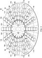
- the open-cavity treatment device 50 includes a plurality of encapsulated leg members 90 that may be coupled to a non-adherent drape 108.
- the non-adherent drape and plurality of encapsulated leg members 90 are supported by the abdominal contents 46.
- One or more of the plurality of encapsulated leg members 90 may be placed in or proximate a first paracolic gutter 92, and one or more of the plurality of encapsulated leg members 90 may be placed in or proximate a second paracolic gutter 94.
- the plurality of encapsulated leg members 90 may be placed at other desired locations, e.g., pelvic cavity, behind the liver, etc.
- Each of the plurality of encapsulated leg members 90 are coupled to the central connection member 96.
- the plurality of encapsulated leg members 90 and the central connection member 96 are in fluid communication.
- Both the plurality of encapsulated leg members 90 and the central connection member 96 are formed with fenestrations 98, 100, 102, 104 that allow fluids in the abdominal cavity 32 to pass.
- the fenestrations 98, 100, 102, 104 may take any shape, such as circular openings, rectangular openings, polygons, etc., but are presented in this illustrative embodiment as slits (elongated openings).
- the open-cavity treatment device 50 includes the non-adherent drape 108 that may be formed of any non-adherent film material that helps prevent tissue from adhering to the non-adherent drape 108.
- the non-adherent drape 108 is formed from a breathable polyurethane film.
- the non-adherent drape 108 is formed with a plurality of fenestrations 110, which may take any shape.
- the open-cavity treatment device 50 includes the central connection member 96 to which the plurality of encapsulated leg members 90 are coupled.
- the central connection member 96 may be encapsulated, including the edges of the central connection member 96, except at leg coupling areas 112 that allow fluid communication with the encapsulated leg members 90.
- the central connection member 96 has apertures or fenestrations, e.g., apertures 104, which allow fluid communication between a connection manifold member 114 and the manifold 64.
- the fluid communication between the connection manifold member 114 and the manifold 64 may be via the deep-tissue closure device 54.
- Each of the encapsulated leg members 90 may be formed with a plurality of defined leg modules, such as leg modules 116.
- a manipulation zone 118 may be located between adjacent leg modules 116. The manipulation zones 118 facilitate movement of the open-cavity treatment device 50 and cutting of the open-cavity treatment device 50 to size the open-cavity treatment device 50.
- Each encapsulated leg member 90 has a leg manifold member 120, which may be a single manifold member that runs between the leg modules 116 or may be formed with discrete components of a manifold material that make up the leg manifold member 120.
- the leg manifold member 120 is disposed within an interior portion 122 of the encapsulated leg member 90.
- the leg manifold member 120 has a first side 124 and second, inward-facing (patient-facing) side 126.
- a first leg encapsulating member 128, which is formed with the fenestrations 98, is disposed on the first side 124 of the leg manifold member 120.
- a second leg encapsulating member 130 which has fenestrations 100, is disposed on the second, inward-facing side 126 of the leg manifold member 120.
- the second leg encapsulating member 130 may be a portion of the non-adherent drape 108.
- fluid may flow between the adjacent leg modules 116.
- fluid is able to enter the fenestrations 98 and 100 and flow into the leg manifold member 120 and then flow toward the central connection member 96 as represented by the flow arrows 132.
- first leg encapsulating member 128 and the second leg encapsulating member 130 may be a single sheet folded over the leg manifold member 120 and sealed.
- the second leg encapsulating member 130 is a portion of the non-adherent drape 108.
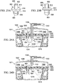
- the leg manifold member 120 has peripheral edges 136 that are also covered by a portion of the first leg encapsulating member 128.
- the peripheral edges 136 include a first lateral edge 137 and a second lateral edge 139.
- the first leg encapsulating member 128 covers the first side 124 and the peripheral edges 136 and extends onto a first surface 138 of the non-adherent drape 108 and thereby forms extensions 140.
- the extensions 140 are coupled to the second leg encapsulating member 130 by any attachment device, e.g., welding (e.g., ultrasonic or RF welding), bonding, adhesives, cements, etc., and in this example by welds 142.
- the central connection member 96 is formed with the connection manifold member 114 that is encapsulated with a first connection encapsulation member 146, which has fenestrations 102, and a second connection encapsulation member 152, which has fenestrations 104.
- the first connection encapsulation member 146 is disposed on a first side 148 of the connection manifold member 114.
- a second, inward-facing side 150 of connection manifold member 114 has the second connection encapsulation member 152 disposed proximate to the second, inward-facing side 150.
- the first connection encapsulation member 146 has a peripheral edge 154.
- the second connection encapsulation member 152 has a peripheral edge that corresponds with the peripheral edge 154 of the first connection encapsulation member 146.
- the peripheral edge 154 of the first connection encapsulation member 146 is coupled to the peripheral edge of the second connection encapsulation member 152, except at the leg coupling areas 112 in order to provide flow channels for fluid within the encapsulated leg members 90 to flow into the connection manifold member 114 as suggested by reference arrows 156 in FIGURE 4 . Fluid may also enter directly into the connection manifold member 114 by flowing through the fenestrations 104 as suggested by arrows 158.
- the deep-tissue closure device 54 is deployed proximate to the first connection encapsulation member 146.
- the reduced pressure is communicated through the deep-tissue closure device 54 and that causes fluid to flow from the connection manifold member 114 through the fenestrations 102, through the deep-tissue closure device 54, and into the manifold 64 as is suggested by arrows 160.
- the fluid continues to flow in the direction of the reduced-pressure interface 72 and from there flows to the first reduced-pressure delivery conduit 76.
- FIGURES 6-8 another illustrative embodiment of an open-cavity treatment device 202, which might be used with the reduced-pressure, abdominal treatment system 30 of FIG. 1 , is presented.
- the open-cavity treatment device 202 is analogous in most respects to the open-cavity treatment device 50 of FIGURES 1-5 .
- the open-cavity treatment device 202 has a non-adherent drape 204, a plurality of encapsulated leg members 206, and a central connection member 208.
- the non-adherent drape 204 is formed with an oval or arcuate shape, but various shapes are possible.
- the non-adherent drape 204 is formed with a plurality of fenestrations 205 therethrough.
- the non-adherent drape 204 also forms a second leg encapsulating member 228 and a second connection encapsulation member (not shown, but see by analogy 152 in FIGURE 4 ), and the fenestrations 205 in the non-adherent drape 204 serve as flow channels for the encapsulated leg members 206 and the central connection member 208 on the second, inward-facing side.
- Each of the plurality of encapsulated leg members 206 may be formed with a plurality of leg modules 210 with manipulation zones 212 between adjacent leg modules 210.
- the manipulation zones 212 facilitate maneuvering of the plurality of encapsulated leg members 206 within the abdominal cavity and provide an easier location at which to cut the encapsulated leg members 206 when the open-cavity treatment device 202 is being sized.
- visual indicia 214 may be added on the non-adherent drape 204 to help the healthcare provider know where to cut the non-adherent drape 204 for different sizes of application within the abdominal cavity.
- the visual indicia 214 may include cut lines formed with biocompatible ink or welds or fenestrations or other markings that run, at least in part, through the manipulation zones 212.
- the visual indicia 214 may also show size graduations.
- the encapsulated leg members 206 are formed with a leg manifold member 218 having a first side 220 and a second, inward-facing side 222.
- a first leg encapsulating member 224 covers the first side 220 of the leg manifold member 218 and covers lateral edges 226 of the leg manifold member 218.
- the second, inward-facing side 222 of the leg manifold member 218 is covered by a second leg encapsulating member 228, which in this embodiment is a portion of the non-adherent drape 204.
- the first leg encapsulating member 224 is coupled to the second leg encapsulating member 228 by any means known in the art, e.g., welding (e.g., ultrasonic or RF welding), bonding, adhesives, cements, etc.
- welding e.g., ultrasonic or RF welding
- the first leg encapsulating member 224 is coupled to the second leg encapsulating member 228 by a weld 230.
- the weld 230 may be formed on a perimeter portion of each leg module 210 or elsewhere.
- the central connection member 208 is formed analogously to the central connection member 96 in FIG. 4 .
- the first connection encapsulation member 234 and the second connection encapsulation member (not shown but analogous to second connection encapsulation member 152 in FIG. 4 ) are coupled along a peripheral edge 232 using a weld 233 or other coupling means, e.g., welding (e.g., ultrasonic or RF welding), bonding, adhesives, cements, etc..
- welding e.g., ultrasonic or RF welding
- the peripheral edge 232 of the first encapsulation member 234 and the second encapsulation member are not coupled in a way that closes off fluid flow between the encapsulated leg members 206 and the central connection member 208; that is, a flow path for fluids to flow from the encapsulated leg members 206 into the central connection member 208 exists.
- the non-adherent drape 204 that is formed with fenestrations 205 and that may have visual indicia 214 is placed on a substantially flat surface or otherwise presented on a plane.
- the leg manifold members 218 are placed onto the non-adherent drape 204.
- the central connection member 208 is placed on the non-adherent drape 204.
- the central connection member 208 may be formed as an integral member with the leg manifold members 218, and in that case, the central connection member 208 and the leg manifold members 218 would be placed simultaneously.
- the first connection encapsulation member 234 is placed on the central connection member 208, and the first leg encapsulating member 224 is placed on first side, or top (for the orientation shown in FIG. 6 ), of the leg manifold members 218. Then welds 230 and 233 are applied. Thus, the open-cavity treatment device 202 is formed.
- a first non-adherent drape 204 which includes fenestrations 205, may have the leg manifold members 218 and the central connection member 208 placed on the first non-adherent drape 204. Then, a second non-adherent drape, which has fenestrations, is placed over the first non-adherent drape 204, the leg manifold members 218, and the central connection member 208. Then a plurality of welds (e.g., thermal or RF) are made, and the perimeter of the two non-adherent drapes may be welded. In addition, other points on the drape may be welded together.
- welds e.g., thermal or RF
- the two non-adherent drapes may initially not have fenestrations, and fenestrations may be added separately to the non-adherent drapes after assembly so that the fenestrations line up.
- the fenestrations may also be formed with an electrical member that cuts and seals simultaneously to form "button hole" fenestrations through the two non-adherent drapes at the locations where the leg manifold and the central connection member are absent.
- FIGURE 9 another illustrative embodiment of an open-cavity treatment device 302 is presented.
- the open-cavity treatment device 302 is similar in most respects to that of the open-cavity treatment device 202 shown in FIGURE 6 .
- the open-cavity treatment device 302 has a plurality of encapsulated leg members 306 and a central connection member 312 on a non-adherent drape 348.
- the open-cavity treatment device 302 differs from the open-cavity treatment device 202 primarily in that a fluid delivery subsystem 345 has been added.
- the fluid delivery subsystem 345 allows various fluids, such as medicines or irrigation fluids, to be delivered into the abdominal cavity.
- the various fluids may then be removed by the action of the plurality of encapsulated leg members 306 and the open-cavity treatment device 302 itself.
- the fluid delivery subsystem 345 includes a central port member 347, which may be placed on or in the central connection member 312, for connecting to a delivery conduit (not shown) that delivers the fluid from a site external to the abdominal cavity to the central port member 347.
- Fluidly coupled to the central port member 347 is a plurality of fluid-delivery conduits 349.
- the fluid-delivery conduits 349 may run anywhere on the non-adherent drape 348.
- the fluid-delivery conduits 349 may run along the sides of the encapsulated leg members 306 or on the opposite side of the non-adherent drape 348.
- the fluid-delivery conduits 349 are shown running through the plurality of encapsulated leg members 306.
- the fluid-delivery conduits 349 are open on their distal ends 351 to allow the delivery of fluid there through.
- fluid delivery conduits 349 may have apertures at various locations for delivering fluid and may be closed at the distal ends 351 or open at the distal ends 351.
- the flow of fluid through the distal ends 351 of the fluid-delivery conduits 349 is suggested by arrows 353.
- the open-cavity treatment device 302 may be used in a fashion analogous to that of the open-cavity treatment devices 50 and 202, but at various times, it may be desirable to deliver a fluid through the fluid delivery subsystem 345. For example, it may be desirable to flush the abdominal cavity with an irrigation fluid or to deliver periodic doses of medicine.
- the deep-tissue closure subsystem 56 of the reduced-pressure, abdominal treatment system 30 may be used for closing deep tissues, such as the fascia 36 and, in particular, to approximate the fascia edges 38.
- the deep-tissue closure subsystem 56 which includes the deep-tissue closure device 54, is shown.
- the deep-tissue closure subsystem 56 is particularly well suited for use within the abdominal cavity 32 that involves a deep tissue, such as in the fascia 36.
- the wound in the fascia 36 is shown with fascia edges 38 that typically define the deep-tissue wound. It is desirable to close or apply a closing force on the deep-tissue wound by proximating the fascia edges 38.
- the deep-tissue closure device 54 helps with this purpose.
- the deep-tissue closure device 54 may be placed on top of the open-cavity treatment device 50 and underneath the fascia 36.
- the deep-tissue closure device 54 includes a contractible matrix 164, which has a first side 166 and a second, inward-facing side 168.
- the contractible matrix 164 is formed with a first plurality of apertures 170 through a contractible matrix material or structure.
- the contractible matrix 164 may also be formed so that a plurality of cells, e.g., open cells 172, is formed on the second, inward-facing side 168.
- the plurality of cells 172 may be formed with cell walls 174, which may include a second plurality of apertures 176.
- the first plurality of apertures 170 may be centered on the cells 172.
- the reduced pressure acts through the first plurality of apertures 170 to provide a gripping force on the fascia 36.
- the gripping force holds, or grips, the fascia 36.
- the reduced pressure may be supplied to the fascia 36 from underneath (for the orientation shown) via fluid communication with the open-cavity treatment device 50, the cells 172, and the first plurality of apertures 170. Reduced pressure may additionally or alternatively be supplied via the manifold 64 and the second plurality of apertures 176.
- the gripping force on the fascia 36 is represented by arrows 178.
- the reduced pressure also urges the contractible matrix 164 inward, i.e., in the direction shown by arrows 29.
- “Inward” in this context means toward a center portion of the reduced-pressure, deep-tissue closure device 54.
- “inward” may be defined as in a direction that would pull the tissue, e.g., the fascia 36, towards the fascia edges 38 of the tissue wound for a deployed reduced-pressure, deep-tissue closure device 54.
- the contractible matrix 164 grips the fascia 36 and goes from a non-contracted position to a contracted position.
- the contractible matrix 164 includes cells that collapse laterally and thereby contract.
- the side walls, which are flexible, of the cells move closer to one another under the influence of reduced pressure. Because the reduced pressure on the first plurality of apertures 170 grips the fascia 36, and the reduced pressure also causes the contractible matrix 164 to contract, a closing force is developed and applied to the fascia 36 that urges the fascia edges 38 into closer approximation. Thus, the fascia 36 experiences a closing force and can be closed or urged into a closed position using reduced pressure.
- the contractible matrix 164 includes a plurality of cells, e.g., cells 172, that collectively define a first volume (V 1 ) when no reduced pressure is applied, e.g., at ambient pressure.
- V 1 first volume
- V 2 second volume
- the second volume is less than the first volume (V 1 ), i.e., V 1 >V 2 , and this change in volume is associated with contraction.
- the deep-tissue closure subsystem 56 is able to provide a closing force on deep tissue, such as fascia 36, and to help provide reduced-pressure treatment within the abdominal cavity 32 and, in particular, to provide reduced-pressure treatment proximate the tissue site 34.
- the reduced pressure may be applied to the tissue site 34 and the abdominal cavity 32 to help promote removal of ascites, exudates or other liquids.
- the reduced pressure may be applied also to stimulate the growth of additional tissue.
- the deep-tissue closure device 54 In using the deep-tissue closure subsystem 56, a number of different embodiments of the deep-tissue closure device 54 may be used. Functionally, it is desirable for the deep-tissue closure device 54 to grip the deep tissue without puncturing the deep tissue and to pull the deep tissue towards the center, e.g., toward the center of a deep-tissue wound 165. When applied to the fascia 36, the deep-tissue closure device 54 approximates the fascia edges 38.
- the contractible matrix 400 for use as part of a reduced-pressure, deep-tissue subsystem is presented.
- the contractible matrix 400 has a first side 402 and a second, inward-facing side 404.
- FIGURE 11 presents the first side 402
- FIGURE 12 presents the second, inward-facing side 404.
- the contractible matrix 400 is formed with a solid circular shape, but numerous other shapes, such as the elliptical shape shown in FIGURE 13 , an arcuate shape, a rectangular shape, an irregular shape, etc., may be used.
- the first side 402 of the contractible matrix 400 has a first plurality of apertures 406 formed there through and that extend to the second, inward-facing side 404.
- a plurality of cells 408 is formed on the second, inward-facing side 404.
- the cells 408 each have an aperture 406 and an open cell portion.
- Each open cell 408 is formed with cell walls 410.
- Each cell wall 410 may have an intercellular aperture through the cell wall 410 to form a second plurality of apertures analogous to the second plurality of apertures 176 in FIGURE 10 .
- the plurality of cells 408 may be formed as honeycomb cells centered around each of the first plurality of apertures 406. Other shapes for the cells 408 are possible as mentioned further below.
- the contractible matrix 500 has a first side and a second, inward-facing side 504.
- the contractible matrix 500 in this particular illustrative embodiment is formed with an oval shape that has a central opening 506, but as shown in FIGURE 11 could be formed without such an opening.
- the second, inward-facing side 504 of the contractible matrix 500 may be formed with a plurality of cells 508, each centered on a first plurality of apertures 510.
- the plurality of cells 508 may be formed by a plurality of interconnected cell walls 512.
- the cell walls might be formed with a second plurality of apertures formed through the cell wall analogous to the second plurality of apertures 176 in FIG. 10 .
- the contractible matrix 520 may be used in the reduced-pressure, deep-tissue closure subsystem 56 of FIGURE 1 .
- the contractible matrix 520 in this illustrative embodiment is rectangular in shape and has a first plurality of apertures 522 that go from a first side 524 to a second, inward-facing side 526 of the contractible matrix 520.
- a second plurality of apertures 528 may connect the first plurality of apertures 522 or some portion thereof.
- the contractible matrix 520 may have apertures 522 on the first side 524 but no corresponding aperture on the second, inward-facing side 526.
- the contractible matrix 400 has cells that open only to the first side 524 and may have apertures 528, which provide reduced pressure into the cells. When reduced pressure is supplied through apertures 528, the deep tissue is gripped by the apertures 522 and the side walls of the cells are pulled into closer proximity causing the contractible matrix 520 to contract.
- a number of different substances might be used to form the contractible matrices, e.g., the contractible matrix 164 of FIGURE 1 , the contractible matrix 400 of FIGURES 11 and 12 , the contractible matrix 500 of FIGURES 13 and 14 , and the contractible matrix 520 of FIGURE 15 .
- a flexible, contractible material is used for the matrices.
- these contractible matrices 164, 400, 500, and 520 may be formed from flexible, thermal plastic elastomers (TPE); thermoplastic urethane (TPU); silicone rubber; etc.
- Foam is not used for the contractible matrices.
- the material from which the contractible matrics are formed preferably avoid the ingrowth of any tissue.
- the contractible matrix could be formed from a sealed or encapsulated foam member that has apertures for gripping the tissue and a reduced-pressure supply interface.
- the contractible matrix may be formed with a TPU honeycomb material that includes honeycomb cells that are formed with fusion bonding.
- the contractible matrix may be formed from a thermal plastic elastomer (TPE) that allows for expansion and contraction in the xy plane (the plane within the page for FIGURE 13 ) while holding a fairly constant dimension in the z direction (coming out of the page on FIGURE 13 ).
- TPE thermal plastic elastomer
- the contractible matrix may have a stronger material (or more material) concentrated in the z direction than in the xy directions.
- voids may be added to prescribe the pattern of collapse.
- the contractible matrix may be formed using a thermoplastic urethane (TPU) material that may have an additional film on the contractible matrix on the first side, e.g., on first side 402 of the contractible matrix 400 of FIGURE 11 .
- TPU thermoplastic urethane
- the surface-wound closure subsystem 60 is now presented. It is desirable to help provide a closing force to the surface wound 180 on the epidermis 44 and, in particular, between the surface-wound edges 182. As shown in FIGURES 1 and 16 , the surface-wound closure subsystem 60 may be used for this purpose.
- the surface-wound closure subsystem 60 develops a closing force represented by arrows 184 that is communicated to the epidermis 44 and urges the surface-wound edges 182 towards each other.
- the surface-wound closure subsystem 60 may include a first attachment member 186 that has a first base member 177 and a first wall 188, or wall member, ( FIGURE 16 ).
- the sealed contracting member 196 may be secured to the wall 188 by a securing device, e.g., adhesive 189.
- the first base member 177 has a first side 190 and a second, inward-facing side 191.
- the first base member 177 and the first wall 188 may be made from numerous materials, but a material is preferred that provides some flexibility.
- the first attachment member 186 may be formed with the first base member 177 and the first wall 188 made from polypropylene, or a rigid silicone, etc.
- a first adhesive 192 may be applied to the second, inward-facing side 191 of the first base member 177 to allow the first base member 177 to be releasably attached directly to a portion of a patient's epidermis 44 or indirectly if a polyurethane film or other sealing member 66 is placed on the epidermis 44 first.
- staples, or sutures, or other invasive approaches might be used to attach the first base member 177.
- the first attachment member 186 may be applied directly on top of the epidermis 44, or on top of the sealing member 66, so that whatever forces are applied on the first attachment member 186 are transmitted directly, or indirectly, to the epidermis 44. References to applying the first attachment member 186 to the epidermis 44 should be deemed to include application on top of the sealing member 66 as well.
- the second attachment member 193 is analogous to the first attachment member 186. While the surface-wound closure subsystem 60 of FIGURE 1 only shows two attachment members 186, 193, other attachment members may be dispersed around the surface wound 180 in a spaced fashion and typically in pairs. Having at least two attachment members, e.g., attachment members 186 and 193, allows the closing force to be developed.
- One or more of the attachment members e.g., attachment member 186, has a reduced-pressure interface 194 for receiving reduced pressure from a second reduced-pressure delivery conduit 195.
- the first attachment member 186 may include the reduced-pressure interface 194 to which the second reduced-pressure delivery conduit 195 is fluidly coupled.
- the surface-wound closure subsystem 60 includes a sealed contracting member 196.
- the sealed contracting member 196 may be formed from the same type of materials as the manifold 64, but it may be desirable to include a material that has fewer apertures or holes through the material.
- the sealed contracting member 196 may be formed from a contracting manifold material that is enveloped by a first sealing member 181 and a second sealing member 183. In addition, it may be desirable in some situations to have a material that will contract less in the vertical (for the orientation shown in FIG. 1 ) and more in the horizontal plane (for the orientation shown FIG. 1 ).
- the sealed contracting member 196 has a first side 197 and a second, inward-facing side 198.
- the sealed contracting member 196 also has a peripheral edge 199.
- the sealed contracting member 196 may be sealed by having the first sealing member 181 ( FIG. 16 ) applied to the first side 197, and the second sealing member 183 applied to the second, inward-facing side 198.
- the peripheral edge 199 may be sealed by a peripheral sealing member 185 having a surface 200 disposed against the peripheral edge 199.
- the wall 188 may also be used to the seal peripheral edge 199.
- the second, inward-facing side 198 may be sealed by placement against the sealing member 66 or the patient's epidermis 44.
- the sealed contracting member 196 might also be sealed by being coated with a gas-impervious material.
- the sealed contracting member 196 may be sealed using polyurethane film or silicone as the sealing members 181, 183 and then ultrasonically welding or RF welding the ends of the sealing members 181, 183 to cover the peripheral edge 199. When reduced pressure is supplied to the sealed contracting member 196, the sealed contracting member 196 contracts to develop the closing force, which is represented by the arrows 184.
- the sealed contracting member 196 may be formed with an opening 187 ( FIG. 1 ) on a portion of the sealed contracting member 196 for receiving an extension portion 179 of the reduced-pressure interface 72.
- the extension portion 179 extends through the sealed contracting member 196 and into the manifold 64.
- the reduced-pressure supply subsystem 62 may have a second reduced-pressure source 84 that delivers reduced pressure to the second reduced-pressure delivery conduit 195, which delivers the reduced pressure to the second reduced-pressure interface 194.
- the second reduced-pressure source 84 could be used to provide reduced pressure to the first reduced-pressure delivery conduit 76 (in addition to or in lieu of first reduced-pressure source 77) as well as to the second reduced-pressure delivery conduit 195.
- the first reduced-pressure source 77 could supply reduced pressure through conduit 86 to the second reduced-pressure conduit in addition to or in lieu of the second reduced-pressure source 84.
- a surface-wound closure device 600 for providing a closing force on a surface wound, e.g., surface wound 180 in FIG. 1 .
- the surface-wound closure device 600 may be used as the surface-wound closure subsystem 60 of FIGURE 1 .
- the surface-wound closure device 600 has a plurality of attachment members: a first attachment member 602, a second attachment member 604, a third attachment member 606, and a fourth attachment member 608.
- Each attachment member 602, 604, 606, 608 has an attachment device for releasably attaching the member to the patient's epidermis (or to a sealing member).
- the first attachment member 602 includes an attachment device that is an adhesive 610 for attachment to the patient's epidermis and similarly, third attachment member 606 has an adhesive 612.
- the second and fourth attachment members also have an attachment device, such as an adhesive, for securing the members to a patient's epidermis. While non-invasive means are generally considered preferable, it may also be that the attachment members 602, 604, 606, 608 may be secured using sutures, staples, or other invasive mechanical devices.
- a wall 614 which is coupled to the plurality of attachment members, forms a circumferential wall having an interior space into which a contracting member 616, or contracting material, is placed.
- the contracting member 616 is attached to the circumferential wall 614 at least at points proximate to each attachment member 602, 604, 606, 608.
- the circumferential wall 614 may be made of polypropylene, rigid silicone, or other semi-rigid material that allows the circumferential wall 614 to flex when in a closing mode, i.e., when reduced pressure is applied.
- the contracting member 616 may be made of the same kind of materials as sealed contracting member 196 in FIGURE 1 .
- the contracting member 616 in operation should be sealed and may be sealed by films, layers, or drapes being applied to a first side 618, or top side (for the orientation shown).
- the contracting member 616 may also be sealed with the circumferential wall 614 covering the peripheral edge, the sealing member may provide a seal on the bottom, and then a film or drape placed over the top.
- the contracting member 616 may simply be enveloped in a polyurethane film that has been welded to form an envelope around the material.
- An opening 620 may be formed through the contracting member 616.
- the opening 620 is for placement of part of a reduced-pressure interface, or port, extending to a manifold below the surface-wound closure device 600.
- a reduced-pressure conduit 622 delivers reduced pressure into the contracting member 616; this may be accomplished by directly applying the reduced-pressure conduit 622 into any portion of the contracting member 616, but is shown using a reduced-pressure interface 624 formed on a portion of the circumferential wall 614.
- the attachment members e.g., first attachment member 602 and second attachment member 604, are placed opposite each other and on each side of a surface wound and releasably attached.
- the first attachment member 602 and the fourth attachment member 608 may be releasably secured to one side of a surface wound at different spaced portions and the attachment members 604 and 606 may be placed on the other side of the surface wound.
- the surface-wound closure device 600 is installed, the surface-wound closure device 600 is in a non-contracted position.
- FIGURE 17B shows the surface-wound closure device 600 in a top view and in a non-contracted position
- FIGURE 17C shows the surface-wound closure device 600 in the contracted position.
- a modular, reduced-pressure wound-closure system 700 which is suitable as another illustrative embodiment of a surface-wound closure subsystem 60, is presented.
- the modular, reduced-pressure wound-closure system 700 uses a number of modular components that may be movably coupled to accommodate various sizes and shapes of wounds and to provide a closing force directed toward a central portion of the surface wound.
- a plurality of attachment-base members such as attachment-base member 702 may be used.
- the attachment-base member 702 has a base 704, which has a first side 706 and a second, inward-facing side 708.
- the second, inward-facing side 708 of the base 704 may have an adhesive (not shown but analogous to 610 in FIG. 17A ) for attaching the attachment-base member 702 to a patient's epidermis (or to a sealing member).
- the adhesive on the second, inward-facing side 708 may be initially covered with a releasable backing material that may be removed before application on the patient.
- the attachment-base member 702 also includes a wall 710 that is coupled to the base 704 or formed integrally with the base 704.
- the wall 710 has a first end 712 and a second end 714.
- the first end 712 may be formed with a first movable connection member 716 that is formed as an integral part or attached to the first end 712.
- the second end 714 may be formed with a second movable connection member 718.
- the wall 710 or base 704 may have a hook member 720 attached to the wall 710 or base 704.
- the hook member 720 may be used to help grip and hold a sealed contracting member 722 (see FIGURE 21A ).
- Each connecting member 726 may be used as part of the modular, reduced-pressure wound-closure system 700.
- Each connecting member 726 has a second wall 728 with a first end 730 and a second end 732.
- the second wall 728 may be shaped to have an arcuate configuration as shown or may be straight.
- the first end 730 may be formed with, or have coupled to the first end 730, a third movable connection member 734.
- the second end 732 may have a fourth movable connection member 736.
- the movable connection members 734 and 736 are sized and configured to cooperate with movable connection members, e.g., movable connection members 716 and 718, in a coordinated fashion that allows relative movement, such as pivotable movement, between each attachment-base member 702 and each adjacent, coupled connecting member 726.
- the movable connection members 734 and 736 are shown as being pin-shaped members.
- the first and second movable connection members 716 and 718 are sockets that are sized and configured to receive the pin shapes of movable connection members 734 and 736.
- a reduced-pressure conduit such as conduit 622 in FIGURE 17A
- a reduced-pressure interface might be used on the wall 710 of the attachment-base member 702.
- the attachment-base member 702 might be modified to form a reduced-pressure interface member 740 as shown in FIGURE 20 .
- the reduced-pressure interface member 740 is analogous to that of the attachment-base member 702 except that a reduced-pressure interface 742 has been included.
- the reduced-pressure interface 742 may be a port 744 that extends through a wall 746.
- FIGURES 21A and 21B The previously presented modular components, attachment-base member 702, connecting member 726, and reduced-pressure interface member 740, may be combined to form various shapes; one example is shown in FIGURES 21A and 21B with the modular, reduced-pressure wound-closure system 700 shown around and over a surface wound 701.
- the modular, reduced-pressure wound-closure system 700 is shown with a plurality of attachment-base members.
- the modular, reduced-pressure wound-closure system 700 includes the first attachment-base member 702, a second attachment-base member 750, and a third attachment-base member 752.
- a fourth attachment-base member is shown, but has been modified to form the reduced-pressure interface member 740, which has the reduced-pressure interface 742.
- a reduced-pressure conduit 754 may be coupled to the reduced-pressure interface 742.
- a plurality of movable connecting members is used to connect each of the plurality of attachment-base members 702, 750, 752, 740 (interface).
- the attachment-base member 702 is movably coupled at the first end 712 to the first connecting member 726 at the second end 732 of the first connecting member 726.
- the second attachment-base member 750 is movably coupled to the second connecting member 756.
- the second connecting member 756 is also movably coupled to the third attachment-base member 752.
- the third attachment-base member 752 is movably coupled to a third connecting member 758, which is also movably coupled to the reduced-pressure interface member 740.
- the reduced-pressure interface member 740 is also movably coupled to a fourth connecting member 760.
- the plurality of attachment-base members and plurality of connecting members form a circumferential wall 780 defining an interior space 781 into which sealed contracting member 722 is disposed.
- alternating members of the plurality of attachment-base members and plurality of connecting members provide for connections that move and are thus movably coupled. Movably coupling the members is helpful when the modular, reduced-pressure wound-closure system 700 goes from the non-contracted position of FIGURE 21A to the contracted position shown in FIGURE 21B . It will also be appreciated that while only four connecting members and four attachment-base members are shown in this illustration, any number of these components might be used for bigger or smaller applications. For example, a modular, reduced-pressure closure system 800 in FIGURE 22 shows a much larger system configuration.
- the modular, reduced-pressure closure system 800 in this illustrative embodiment includes a plurality of attachment-base members having seven attachment-base members 802 and another that has been modified to form a reduced-pressure interface 804.
- the modular, reduced-pressure closure system 800 also includes a plurality of connecting members, which in this illustrative embodiment includes eight connecting members 806.
- the plurality of attachment-base members 802 and the plurality of connecting members 806 are movably coupled to form a circumferential wall 808 that defines an interior space 810.
- a sealed contracting member 812 is placed within the interior space 810 and is coupled to at least the plurality of attachment-base members 802.
- the reduced-pressure connector 900 is operable to fluidly connect two different compartments or areas.
- the reduced-pressure connector 900 has a first end 902 and a second end 904.
- An entry portion 906 is formed on the second end 904.
- the entry portion 906 may be shaped as an inverted conical section to facilitate insertion through various materials, such as sealing members and manifolds.
- a plurality of flutes 908 may be located to facilitate fluid flow.
- a flange portion 910 may be formed between the first end 902 and the second end 904.
- the flange portion 910 has a first surface 912 and a second surface 914.
- the first end 902 may also be shaped and configured for easy entry through a sealing member or other material.
- Two different, illustrative applications of the reduced-pressure connector 900 are shown in FIGURES 24A and 24B .
- FIGURE 24A a portion of a reduced-pressure, wound-closure and treatment system 1000 is presented.
- the reduced-pressure, wound-closure and treatment system 1000 is analogous in many respects to the surface-wound closure subsystem 60 of FIGURE 1 .
- a manifold 1018 is placed within a body cavity, e.g., an abdominal cavity 1010, to help provide reduced-pressure treatment therein.
- the manifold 1018 is shown proximate to subdermal tissue 1014 and a surface wound 1011.
- a sealing member 1032 is placed on the patient's epidermis 1008 over the abdominal cavity 1010 and the surface wound 1011.
- the surface wound has wound edges 1012.
- the sealing member 1032 has an adhesive 1034 that helps to form a pneumatic seal with the epidermis 1008.
- the sealing member 1032 as applied forms a pneumatic seal over the abdominal cavity 1010.
- a portion 1071 of a wound-closure device or subsystem is also presented.
- the portion 1071 includes a portion of a sealed contracting member 1088.
- the sealed contracting member 1088 is sealed, at least in part, by a first sealing member 1096 and a second sealing member 1098.
- the sealed contracting member 1088 is attached, at least at certain portions, to the patient's epidermis 1008.
- reduced pressure is supplied to an interior of the sealed contracting member 1088, the sealed contracting member 1088 contracts and thereby pulls towards a central portion and develops a closing force that is transmitted to the surface wound 1011.
- reduced pressure is supplied by a reduced-pressure source to a reduced-pressure conduit 1042.
- the reduced-pressure conduit 1042 is fluidly coupled to a reduced-pressure interface 1038, which has an extension portion 1102.
- the extension portion 1102 extends through the sealing member 1032 and into the manifold 1018.
- reduced pressure is delivered to the manifold 1018 and pulls fluids towards the extension portion 1102 as suggested by arrows 1044.
- the reduced-pressure connector 900 has been added.
- the reduced-pressure connector 900 is deployed with the first end 902 within the interior of the sealed contracting member 1088 and the second end 904 within the manifold 1018.
- the reduced-pressure connector 900 thereby fluidly couples the interior of the sealed contracting member 1088 with the manifold 1018. Reduced pressure is thereby delivered from the reduced-pressure interface 1038, to the manifold 1018, and to the interior of the sealed contracting member 1088. The reduced pressure delivered through the reduced-pressure connector 900 pulls fluids within the sealed contracting member 1088 as suggested by arrows 1045.
- the first surface 912 of the reduced-pressure connector 900 abuts the sealing member 1032 and the second surface 914 abuts the manifold 1018.
- the reduced-pressure connector 900 may be deployed in numerous ways. For example, with reference to FIGURE 17A , the reduced-pressure connector 900 can be placed over a cell, e.g., cell 625, of the contracting member 616, and pushed through the sealing member thereon.
- the entry portion 906 is shaped to facilitate such an entry.
- the sealing member thereon should self-seal after insertion, but an additional portion of sealing material could also be added over the insertion point.
- the reduced-pressure connector 900 is pushed into the sealed contracting member 616 until the second surface 914 abuts the second (bottom for orientation shown) sealing member 1098 and the entry portion 906 extends out of the contracting member 616.
- the entry portion 906 can then be inserted through the sealing member 1032 and into the manifold 1018.
- numerous approaches may be taken for deploying the reduced-pressure connector 900 and the reduced-pressure connector 900 may take many different configurations, but the deployed reduced-pressure connector 900 functionally provides a fluid coupling of the sealed contracting member 1088 and the manifold 1018.
- the extension portion 1102 of the reduced-pressure interface 1038 terminates within the sealed contracting member 1088 and delivers reduced pressure within the sealed contracting member 1088.
- the reduced-pressure connector 900 is deployed in the same manner as previously presented, but now delivers reduced pressure to the manifold 1018. In other words, fluids are drawn through the manifold 1018, through the reduced-pressure connector 900, through an interior of the sealed contracting member 1088 to the extension portion 1102 of the reduced-pressure interface 1038 and then through the reduced-pressure conduit 1042.
- the modular, reduced-pressure closure system 1200 includes a spacing member, e.g., a flexible strap 1202, which is shown in a linear position in FIGURE 25 and shaped into a closed loop 1204 in FIGURE 27 .
- the flexible strap 1202 may be shaped into the closed loop 1204 around a surface wound 1206, such as an opening on a patient's abdomen.
- a plurality of modular closing members 1208 is selectively coupled to the flexible strap 1202.
- the number of modular closing members 1208 included in the plurality of modular closing members on the flexible strap 1202 is determined by the size of the closed loop 1204 needed to surround the surface wound 1206. Thus, to cover the surface wound 1206 in FIGURE 27 , eight modular closing members 1208 have been included on the flexible strap 1202. While a flexible strap 1202 has been referenced, any spacing member that holds the modular closing members 1208 in a spaced relationship around the surface wound 1206 may be used.
- the spacing member may be one or more tie wires that hold the modular closing members 1208 in a spaced relationship or a flexible adhesive film placed on top of the modular closing members 1208 that hold the modular closing members 1208 in a spaced relationship.
- each of the modular closing members 1208 has a first end 1210 and a second end 1212.
- a connection member 1214 is coupled to the first end 1210 of each modular closing member 1208.
- each connection member 1214 includes an attachment loop 1216 through which the flexible strap 1202 may be placed.
- the attachment loops 1216 allow each modular closing member 1208 to be positioned in a desired location along the flexible strap 1202.
- a portion of each attachment loop 1216 may interface with one of a plurality of strap openings 1218 to help hold the connection member 1214 in a desired position on the flexible strap 1202.
- the second reduced-pressure interface 1226 is shown coupled to the connection member 1214.
- a reduced-pressure conduit 1227 is fluidly coupled to the second reduced-pressure interface 1226 in order to provide reduced pressure to the second reduced-pressure interface 1226.
- the second reduced-pressure interface 1226 delivers the reduced pressure to a sealed contracting member 1228 and may function as a pin to hold the connection member 1214 in place relative to the flexible strap 1202.
- the second reduced-pressure interface 1226 may extend through an opening in connection member 1214, through the attachment loop 1216, through the flexible strap 1202 and into the sealed contracting member 1228.
- the sealed contracting member 1228 may be held to a base 1231 by an adhesive layer 1229.
- a peripheral edge 1233 of the sealed contracting member 1228 may be held to a wall 1251 of connection member 1214 by an adhesive layer 1235.
- reduced pressure can be supplied to the modular closing member 1208 and more particularly to the sealed contracting member 1228.
- FIGURES 28 and 29 show alternative ways of providing reduced pressure to the sealed contracting member 1228 as will be described further below.
- the sealed contracting member 1228 is made of the same or similar materials as contracting member 196 ( FIG. 1 ), 616 ( FIG. 17A ), and 722 ( FIG. 21A ).
- the sealed contracting member 1228 is sealed to form a pneumatic seal about the sealed contracting member 1228.
- An adhesive layer 1229 may be used to hold the sealed contracting member 1228 to the base 1231.
- An adhesive layer 1235 may be also be used to attach the peripheral edge 1233 of the sealed contracting member 1228 to the wall 1251.
- attachment members 1220 may be coupled to each of the second ends 1212 of the modular closing members 1208.
- each of the attachment members 1220 may be formed with a base 1222 and a wall 1224.
- An adhesive layer may be used to hold the sealed contracting member 1228 to the base 1222.
- An adhesive layer may also be used to hold the sealed contracting member to the wall 1224.
- An adhesive may be used to hold the inward-facing side 1236 of the base 1222 against the patient's epidermis.
- Reduced pressure may be provided to a sealed contracting member 1308 through the connection member.
- the modular closing member may have a connection member 1316 that selectively attaches to a flexible strap 1302.
- An adhesive 1330 may be used to hold the sealed contracting member 1308 to the connection member 1316.
- the connection member 1316 may have a wall 1324 and a base 1322.
- a reduced-pressure interface 1327 may be formed on the base 1322 and configured to enter the sealed contracting member 1308.
- the reduced-pressure interface 1327 is sized and configured to engage a manifold 1380, which is in fluid communication, or is fluidly coupled, to a reduced-pressure source. The reduced pressure is delivered to the manifold 1380.
- an attachment member 1420 which has a base portion 1422 and a wall 1424, is shown with an alternative reduced-pressure interface 1426.
- the reduced-pressure interface 1426 is formed through the wall 1424.
- a reduced-pressure conduit 1427 delivers reduced pressure from a reduced-pressure source to the reduced-pressure interface 1426.
- the reduced-pressure interface 1426 delivers reduced pressure to a sealed contracting member 1428.
- the sealed contracting member 1428 may be held to the base 1422 by an attachment device, e.g., adhesive 1430.
- the base 1422 may be held by an attachment device 1432, e.g., adhesive 1436, to the patient's epidermis.
- the sealed contracting member 1428 may also be held by an attachment device 1432, e.g., adhesive 1434, to the wall 1424.
- the modular, reduced-pressure closure system 1200 is used by the healthcare provider who first assesses the size of the surface wound 1206 and determines the number of modular closing members 1208 that are appropriate for the size of the wound.
- a lookup table might be provided to suggest the number based on the linear measurement of the circumference of the surface wound 1206.
- An appropriate number, which make up the desired plurality of modular closing members 1208, are then selectively coupled to the flexible strap 1202.
- the flexible strap 1202 is shaped into the closed loop 1204 around the surface wound 1206 and is preferably disposed inboard of the peripheral edges of the surface wound 1206.
- the closed loop 1204 is secured as a loop using any number of means, such as a ratchet, snap, a fastener on the flexible strap 1202, ratchet ties, flexible peg and slot members, etc.
- each of the plurality of attachment members 1220 are attached to the patient's epidermis proximate the edge of the surface wound 1206.
- the statement that each of the plurality of attachment members 1220 are attached to the epidermis may include that the attachment member 1220 is attached on top of a sealing member being used for reduced-pressure treatment.
- a closing force is developed as represented by arrows 1240.
- the closed loop 1204 provides an open area in the middle of the loop which readily accommodates a reduced-pressure interface 1242 that may be used to supply reduced pressure to a portion of a reduced-pressure treatment system (see, e.g., subsystem 58 in FIG. 1 ).
- the healthcare provider may first put in an open-cavity treatment device 50 as part of an open-cavity treatment subsystem 52.
- the open-cavity treatment device 50 may be sized initially to fit the particular application.
- the open-cavity treatment device 202 may be cut along visual indicia 214 through the manipulation zones 212 to properly size the dressing.
- the open-cavity treatment device 50 is placed within the abdominal cavity 32 and on top of the abdominal contents 46.
- the encapsulated leg members 90 of the open-cavity treatment device 50 may be tucked and worked into desired locations, e.g., the paracolic gutters 92, 94, pelvic cavity, behind a patient's liver, etc.
- the healthcare provider may place the deep-tissue closure device 54 on the first side (or top for the orientation shown) of the open-cavity treatment device 50.
- the deep-tissue closure device 54 which is part of a deep-tissue closure subsystem 56, may need to be sized by cutting the deep-tissue closure device 54 to a desired size to accommodate the deep-tissue wound.
- the healthcare provider may help to position layers of tissue, namely fascia 36, on the first side (or top for the orientation shown) of the deep-tissue closure device 54.
- the manifold 64 may be inserted within the abdominal cavity 32 and on top of a portion of the deep-tissue closure device 54.
- the sealing member 66 may then be placed over the opening of the abdominal cavity 32 and on the epidermis 44 to provide a pneumatic seal. This may be done by removing releasable backing from the adhesive 70 and then placing the adhesive 70 against the epidermis 44. Then, to help provide additional closing force and support, the surface-wound closure subsystem 60 may be applied. Any of numerous possible embodiments of a surface-wound closure subsystem may be used. In addition, various other subsystems and alternatives might be used as part of the reduced-pressure, abdominal treatment system 30.
- the first attachment member 186 may be applied on one side of the surface-wound edges 182 and a second attachment member 193 may be applied generally at a position opposite the first attachment member 186 and on the other side of surface-wound edge 182.
- the attachment members 186 and 193 may be attached by removing releasable backing from an adhesive layer, e.g., first adhesive 192 on the first attachment member 186, and applying the adhesive against the sealing member 66.
- a portion of the reduced-pressure interface 72 may then be placed into opening 187 of the surface surface-wound closure subsystem 60 and into the manifold 64.
- the first reduced-pressure delivery conduit 76 may be fluidly coupled to the reduced-pressure interface 72 and to the reduced-pressure supply subsystem 62, which delivers reduced pressure to the first reduced-pressure delivery conduit 76.
- the surface surface-wound closure subsystem 60 includes at least one second reduced-pressure interface 194, which is fluidly coupled to a second reduced-pressure delivery conduit 195.
- the second reduced-pressure delivery conduit 195 is fluidly coupled to the reduced-pressure supply subsystem 62, which delivers a reduced pressure into the second reduced-pressure delivery conduit 195.
- the healthcare provider may then activate the reduced-pressure supply subsystem 62, which delivers reduced pressure (a first reduced pressure or treatment-reduced-pressure) to the reduced-pressure treatment subsystem 58 and in particular to the manifold 64.
- reduced pressure is also communicated to the open-cavity treatment device 50 and the deep-tissue closure device 54.
- reduced pressure might also be supplied to the surface-wound closure subsystem 60 by the manifold 64, but in the illustrative embodiment of FIGURE 1 , reduced pressure (a second reduced pressure or closing-reduced-pressure) is supplied by the second reduced-pressure delivery conduit 195 to the sealed contracting member 196 causing the sealed contracting member 196 to contract and pull the surface-wound edges 182 of the epidermis 44 together.
- reduced pressure a second reduced pressure or closing-reduced-pressure
- the reduced-pressure, abdominal treatment system 30, and particularly the open-cavity treatment device 50 helps remove ascites and other fluids from the abdominal cavity 32 and the tissue site 34 without adhering to the abdominal contents 46.
- the reduced-pressure, abdominal treatment system 30 utilizes the deep-tissue closure subsystem 56 to help close the fascia 36 without the fascia "rolling" or causing other problems and without requiring puncture wounds to the fascia 36.
- the reduced-pressure, abdominal treatment system 30 helps generally to provide reduced-pressure treatment within the abdominal cavity 32 by way of the reduced-pressure treatment subsystem 58, which includes the manifold 64.
- the reduced-pressure, abdominal treatment system 30 also helps close the surface wound 180 in the epidermis 44 by using the surface surface-wound closure subsystem 60.
Abstract
Description
- The present invention claims the benefit, under 35 USC § 119(e), of the filing of
U.S. Provisional Patent Application serial number 61/109,486 U.S. Provisional Patent Application serial number 61/109,390 U.S. Provisional Patent Application serial number 61/109,410 U.S. Provisional Patent Application serial number 61/109,448 - The present invention relates generally to medical treatment systems and, more particularly, to reduced-pressure, abdominal treatment systems and methods.
- Whether the etiology of a wound, or damaged area of tissue, is trauma, surgery, or another cause, proper care of the wound is important to the outcome. Unique challenges exist when the wound involves locations that require reentry, for example, the peritoneal cavity and more generally the abdominal cavity. Often times when surgery or trauma involves the abdominal cavity, establishing a wound management system that facilitates reentry allows for better and easier care and helps to address such things as peritonitis, abdominal compartment syndrome (ACS), and infections that might inhibit final healing of the wound and the internal organs. In providing such care, it may be desirable to remove unwanted fluids from the cavity, help approximate the fascia and other tissues, and finally to help provide a closing force on the wound itself at the level of the epidermis.
- Currently, an abdominal opening on the epidermis may be closed using sutures, staples, clips, and other mechanical devices to allow the skin, or epidermis, to be held and pulled. Such devices often cause puncture wounds or other wounds. If severe edema occurs, tremendous pressure may be placed on the closure device with potential harm resulting. For example, if the pressure rises due to edema, the sutures may tear out.
- With respect to the overall system for allowing reentry into the abdominal cavity, a number of techniques have been developed. One approach is to place towels down into the abdominal cavity and then use clips, such as hemostats, to close the skin over the towels. While simple and fast, the results have been regarded as suboptimal. Another approach is the "Bogota bag." With this approach, a bag is sutured into place to cover the open abdomen in order to provide a barrier. Still another approach, sometimes called a "vac pack," has been to pack towels in the wound and then place a drain into the abdomen and cover the abdomen with a drape. Finally, a reduced pressure approach has been used. Such an approach is shown in
U.S. Patent 7,381,859 to Hunt et al. and assigned to KCI Licensing, Inc. of San Antonio, Texas.U.S. Patent 7,381,859 is incorporated herein by reference for all purposes. - A number of deep tissues, e.g., fat, muscle, or particularly fascia, may be addressed when one is temporarily closing the abdomen. Unless otherwise indicated, as used herein, "or" does not require mutual exclusivity. If not addressed, the deep tissue may retract further into the abdominal cavity and subsequently cause difficulties. The surgeon may suture the deep tissue, e.g., the fascia, while placing the fascia under tension. This can be problematic, however, if reduced-pressure treatment in the area is desired or if the dressing needs to be replaced. Moreover, suturing the deep tissue can at times cause necrosis. At the same time, if the deep tissue, notably the fascia, is not closed, this situation can lead to hernias and other complications.
- In addition to accessing the abdominal cavity for reentry, it is desirable to remove fluids. It may also be desirable to provide reduced-pressure therapy to the tissue site, including wounds that may be within the abdominal cavity. Clinical studies and practice have shown that providing a reduced pressure in proximity to a tissue site augments and accelerates the growth of new tissue at the tissue site. The applications of this phenomenon are numerous, but application of reduced pressure has been particularly successful in treating wounds. This treatment (frequently referred to in the medical community as "negative pressure wound therapy," "topical negative pressure," "reduced pressure therapy," or "vacuum therapy") provides a number of benefits, including faster healing and may increase formulation of granulation tissue.
- Problems with existing abdominal treatment systems and methods are addressed by the systems, apparatus, and methods of the illustrative embodiments described herein. According to one illustrative embodiment, a reduced-pressure abdominal treatment system includes an open-cavity treatment device for providing reduced-pressure treatment proximate a patient's abdominal contents; a deep-tissue closure device for applying a closing force on a deep-tissue, e.g., a patient's fascia; and a reduced-pressure treatment subsystem for providing reduced-pressure treatment in the patient's abdominal cavity. The reduced-pressure treatment system may also include a surface-wound closure subsystem for providing a closing force on the patient's epidermis. The reduced-pressure treatment system may also include a reduced-pressure supply subsystem operable to develop reduced pressure for use in the open-cavity treatment device, deep-tissue closure device, the reduced-pressure treatment subsystem, and the surface-wound closure subsystem.
- According to another illustrative embodiment, a method of treating an open abdominal cavity includes the step of disposing in the abdominal cavity an open-cavity treatment device, which has a first side and a second, inward-facing side. The second, inward-facing side of the open-cavity treatment device is disposed proximate the patient's abdominal contents. The method of treating an open abdominal cavity further includes the step of disposing in the open abdominal cavity a deep-tissue closure device, which has a first side and a second, inward-facing side. The deep-tissue closure device is disposed with the second, inward-facing side of the deep-tissue closure device proximate the first side of the open-cavity treatment device and the first side of the deep-tissue closure device proximate the fascia. The method of treating an open abdominal cavity may further include the steps of disposing a manifold within the patient's abdominal cavity; forming a pneumatic seal over the patient's abdominal cavity; fluidly coupling a first reduced-pressure interface to the manifold; releasably attaching a first attachment member to a first portion of the patient's epidermis proximate an edge of the surface wound; and releasably attaching a second attachment member to a second portion of the patient's epidermis proximate the edge of the surface wound. The first attachment member is spaced from the second attachment member. The method of treating an open abdominal cavity further includes the steps of providing a sealed contracting member coupled to the first attachment member and the second attachment member and operable to contract when placed under reduced pressure; and supplying reduced pressure to the open-cavity treatment device, the deep-tissue closure device, the manifold, and the sealed contracting member.
- According to another illustrative embodiment, a method of manufacturing a system for treating an open abdominal cavity of a patient includes the steps of forming an open-cavity treatment device for providing reduced-pressure treatment to a patient's abdominal cavity; forming a deep-tissue closure device for applying a closing force on a deep-tissue wound on a patient's fascia; and forming a surface-wound closure subsystem for providing a closing force on a surface wound on the patient's epidermis. The method of manufacturing may also include the step of providing a reduced-pressure supply subsystem.
- Other objects, features, and advantages of the illustrative embodiments will become apparent with reference to the drawings and detailed description that follow.
-
-
FIGURE 1 is a schematic, cross sectional view, with a portion in block diagram, of an illustrative reduced-pressure, abdominal treatment system; -
FIGURE 2 is a schematic cross section of a portion of the illustrative reduced-pressure, abdominal treatment system ofFIGURE 1 showing a portion of an encapsulated leg member; -
FIGURE 3 is a schematic cross section of a portion of the illustrative reduced-pressure, abdominal treatment system ofFIGURE 1 showing a portion of an encapsulated leg member; -
FIGURE 4 is a schematic cross section of a portion of the illustrative reduced-pressure, abdominal treatment system ofFIGURE 1 showing a central connection member; -
FIGURE 5 is a schematic, perspective view of the open-cavity, reduced-pressure treatment device ofFIGURE 1 ; -
FIGURE 6 is a schematic, plan view of an open-cavity, reduced-pressure treatment device according to another illustrative embodiment; -
FIGURE 7 is a schematic, plan view of a detail of the treatment device ofFIGURE 6 ; -
FIGURE 8 is a schematic cross section of a portion of the treatment device ofFIGURE 7 taken along line 8-8; -
FIGURE 9 is schematic, perspective view of another illustrative embodiment of an open-cavity, reduced-pressure treatment device; -
FIGURE 10 is a schematic, cross-sectional view of a detail of the illustrative deep-tissue closure subsystem ofFIGURE 1 ; -
FIGURE 11 is a schematic, perspective view, which shows a first side (top), of a contractible matrix according to one illustrative embodiment; -
FIGURE 12 is a schematic, perspective view, which shows a second (inward-facing) side, of the contractible matrix ofFIGURE 11 ; -
FIGURE 13 is a schematic, top view of another illustrative embodiment of a contractible matrix; -
FIGURE 14 is a detail of a portion of the contractible matrix ofFIGURE 13 ; -
FIGURE 15 is a schematic, perspective view of a portion of an illustrative embodiment of a contractible matrix; -
FIGURE 16 is a schematic, cross-sectional view of a portion of the illustrative surface-wound closure subsystem ofFIGURE 1 ; -
FIGURE 17A is a schematic, perspective view of an illustrative embodiment of a reduced-pressure, surface-wound closure subsystem; -
FIGURES 17B and 17C are schematic, plan views of the reduced-pressure, surface-wound closure system ofFIGURE 17A shown in a non-contracted position (FIG. 17B ) and a contracted position (FIG. 17C ); -
FIGURE 18 is a schematic, perspective view of an illustrative embodiment of an attachment-base member for use as part of an illustrative embodiment of a surface-wound closure subsystem; -
FIGURE 19 is a schematic, perspective view of an illustrative embodiment of a connection member for use as part of an illustrative embodiment of a surface-wound closure subsystem; -
FIGURE 20 is a schematic, perspective view of an illustrative embodiment of a reduced-pressure interface member for use as part of an illustrative embodiment of a surface-wound closure subsystem; -
FIGURES 21A and 21B are schematic, plan views of an illustrative embodiment of a reduced-pressure, surface-wound closure subsystem shown in a non-contracted position (FIG. 21A ) and a contracted position (FIG. 21B ); -
FIGURE 22 is schematic, perspective view of an illustrative embodiment of a modular, reduced-pressure, surface-wound closure subsystem; -
FIGURE 23A is a schematic, perspective view of an illustrative reduced-pressure connector; -
FIGURE 23B is an elevational view of the reduced-pressure connector ofFIGURE 23A ; -
FIGURE 24A is a schematic, cross-sectional view of a portion of another illustrative embodiment of a reduced-pressure, wound-closure and treatment system; -
FIGURE 24B is a schematic, cross-sectional view of a portion of another illustrative embodiment of a reduced-pressure, wound-closure and treatment system; -
FIGURE 25 is a schematic, perspective view of an illustrative embodiment of a portion of a reduced-pressure, surface-wound closure subsystem showing, amongst other things, an illustrative embodiment of a plurality of modular closing members; -
FIGURE 26 is a schematic, cross-section of a portion of a modular closing member ofFIGURE 25 ; -
FIGURE 27 is a schematic, perspective view of the illustrative wound-closure subsystem ofFIGURES 25-26 shown applied over a surface wound of a patient; -
FIGURE 28 is a schematic, cross-sectional view of an illustrative embodiment of a portion of an illustrative embodiment of a sealed contracting member; and -
FIGURE 29 is a schematic, cross-sectional view of an illustrative embodiment of an attachment member. - In the following detailed description of the illustrative embodiments, reference is made to the accompanying drawings that form a part hereof. These embodiments are described in sufficient detail to enable those skilled in the art to practice the invention, and it is understood that other embodiments may be utilized and that logical structural, mechanical, electrical, and chemical changes may be made without departing from the spirit or scope of the invention. To avoid detail not necessary to enable those skilled in the art to practice the embodiments described herein, the description may omit certain information known to those skilled in the art. The following detailed description is, therefore, not to be taken in a limiting sense, and the scope of the illustrative embodiments are defined only by the appended claims.
- Referring primarily to
FIGURE 1 , an illustrative embodiment of a reduced-pressure,abdominal treatment system 30 is presented. The reduced-pressure,abdominal treatment system 30 is for use in treating, or managing, a patient'sabdominal cavity 32 and tissue or wounds associated with an open abdomen. As used herein, "wound" signifies a damaged area of tissue. The reduced-pressure,abdominal treatment system 30 may be used to treat ageneral tissue site 34; a deep-tissue wound in a deep tissue, such as infascia 36,muscle 40,fat layer 42; and asurface wound 180 inepidermis 44. The wound in thefascia 36 has fascia edges 38. The surface wound 180 in theepidermis 44 has surface-wound edges 182. Thetissue site 34 is shown on or proximateabdominal contents 46. Thetissue site 34 may be the bodily tissue of any human, animal, or other organism. In this embodiment, thetissue site 34 generally includes tissue in theabdominal cavity 32 and typically tissue proximate theabdominal contents 46. - The reduced-pressure,
abdominal treatment system 30 includes an open-cavity treatment device 50 that is part of an open-cavity treatment subsystem 52. The open-cavity treatment subsystem 52 helps provide reduced-pressure treatment in the patient'sabdominal cavity 32 and provides a non-adherent cover for theabdominal contents 46. The reduced-pressure,abdominal treatment system 30 also includes a deep-tissue closure device 54 that is part of a deep-tissue closure subsystem 56. The deep-tissue closure subsystem 56 applies a closing force on a tissue and is particularly well suited for providing a closing force on a deep tissue, e.g., thefascia 36. The deep-tissue closure subsystem 56 may help approximate the fascia edges 38. The reduced-pressure,abdominal treatment system 30 also provides general reduced-pressure treatment with a reduced-pressure treatment subsystem 58. The surface wound 180 on theepidermis 44, and particularly the surface-wound edges 182, may be urged toward a central portion, or towards each other, by a closing force developed by a surface-wound closure subsystem 60. Finally, the reduced-pressure,abdominal treatment system 30 may include a reduced-pressure supply subsystem 62 that provides reduced pressure to various devices and subsystems within the reduced-pressure,abdominal treatment system 30. Each of the devices and subsystems will be described in more detail further below. - The reduced pressure delivered by the reduced-pressure,
abdominal treatment system 30 may be applied in theabdominal cavity 32 and totissue site 34 to help promote removal of exudates, ascites, or other liquids, bacteria, fibrin, dead tissue, toxins, residual blood, etc. In some instances reduced pressure may be applied to stimulate the growth of additional tissue, and in some instances, only fluid removal may be desired. In the case of a wound at thetissue site 104, the growth of granulation tissue and removal of exudates and bacteria may help to promote healing of the wound. As used herein, "reduced pressure" generally refers to a pressure less than the ambient pressure at thetissue site 34 that is being subjected to treatment. In most cases, this reduced pressure will be less than the atmospheric pressure at which the patient is located. Alternatively, the reduced pressure may be less than a hydrostatic pressure of tissue at thetissue site 34. Unless otherwise indicated, values of pressure stated herein are gauge pressures. - An illustrative embodiment of a reduced-pressure subsystem, e.g., the reduced-
pressure subsystem 58, will now be presented. The reduced-pressure treatment subsystem 58 includes a manifold 64, a sealing member 66 (or over-drape), and a reduced-pressure interface 72. The manifold 64 is shown disposed within theabdominal cavity 32. The sealingmember 66 is placed over the surface wound 180 on theepidermis 44 to form a pneumatic seal over theabdominal cavity 32. - The manifold 64 may take many forms. The term "manifold" as used herein generally refers to a substance or structure that is provided to assist in applying reduced pressure to, delivering fluids to, or removing fluids from a tissue site, e.g.,
tissue site 34. The manifold 64 typically includes a plurality of flow channels or pathways that distribute fluids provided to and removed from the area of tissue around themanifold 64. The manifold 64 may include a plurality of flow channels or pathways that are interconnected to improve distribution of fluids. The manifold 64 may be a biocompatible material that is capable of being placed in contact with tissue and distributing reduced pressure. Examples ofmanifold 64 include, without limitation, devices that have structural elements arranged to form flow channels, cellular foam, such as open-cell foam, porous tissue collections, and liquids, gels and foams that include or cure to include flow channels. The manifold 64 may be porous and may be made from foam, gauze, felted mat, or any other material suited to a particular biological application. In one embodiment, the manifold 64 is porous foam and includes a plurality of interconnected cells or pores that act as flow channels. The porous foam may be a polyurethane, open-cell, reticulated foam, such as a GranuFoam® material provided by Kinetic Concepts, Incorporated of San Antonio, Texas. Other embodiments might include "closed cells" to direct fluid flow in themanifold 64. In some situations, the manifold 64 may also be used to distribute fluids, such as medications, antibacterials, growth factors, and other solutions into theabdominal cavity 32 or at thetissue site 34. Other layers may be included in the manifold 64, such as an absorptive material, wicking material, hydrophobic material, or hydrophilic material. - The sealing
member 66 is placed over theabdominal cavity 32 and the surface wound 180 to provide a pneumatic seal between the sealingmember 66 and the patient'sepidermis 44. The pneumatic seal is adequate for reduced-pressure,abdominal treatment system 30 to hold reduced pressure at thetissue site 34. The sealingmember 66 may be used to secure the manifold 64 on acentral connection member 96 or on a portion of the deep-tissue closure subsystem 56 as shown inFIG. 1 . While the sealingmember 66 may be impermeable or semipermeable, the sealingmember 66 is capable of maintaining reduced pressure at thetissue site 34 after installation of the sealingmember 66 and other system components. The sealingmember 66 may be a flexible over-drape, cover, or film formed from a silicone based compound, acrylic, hydrogel or hydrogel-forming material, or any other biocompatible material that includes the impermeability or permeability characteristics desired for the tissue site. - The sealing
member 66 may further include anattachment device 68 to secure the sealingmember 66 to the patient'sepidermis 44 or to a gasket member around the surface-wound edges 182. Theattachment device 68 may take many forms; for example, an adhesive 70 may be positioned along a perimeter of the sealingmember 66 or any portion of the sealingmember 66 to provide, directly or indirectly, the pneumatic seal with the patient'sepidermis 44. The adhesive 70 might also be pre-applied and covered with a releasable backing, or member, that is removed at the time of application. - The reduced-
pressure interface 72 permits the passage of fluid from the manifold 64 to a first reduced-pressure delivery conduit 76 and vice versa. The reduced-pressure interface 72 may be, as one example, a port orconnector 74. Thus, fluids collected from theabdominal cavity 32 using the manifold 64 may enter the first reduced-pressure delivery conduit 76 via the reduced-pressure interface 72. In another embodiment, the reduced-pressure,abdominal treatment system 30 may exclude the reduced-pressure interface 72 and the first reduced-pressure delivery conduit 76 may be inserted directly into the sealingmember 66 and into themanifold 64. The first reduced-pressure delivery conduit 76 may be a medical conduit or tubing or any other means for transporting a reduced pressure. The first reduced-pressure delivery conduit 76 may be a multi-lumen member for readily delivering reduced pressure and removing fluids. In one embodiment, the first reduced-pressure delivery conduit 76 is a two-lumen conduit with one lumen for fluid transport and one for pressure sensing in fluid communication with a pressure sensor. In another embodiment, the first reduced-pressure conduit 76 may be two separate conduits or a single conduit having two or more lumens. - Reduced pressure may be supplied to the first reduced-
pressure delivery conduit 76 by the reduced-pressure supply subsystem 62, which includes a reduced-pressure source 77. A wide range of reduced pressures may be developed, such as from -50 mm Hg. to -500 mm Hg and more typically in the range of -100 mm Hg to -300 mm Hg. The pressure developed may be constant or varied over time. In one illustrative embodiment, the reduced-pressure source 77 includes preset selectors for -100 mm Hg, -125 mm Hg, and -150 mm Hg. The reduced-pressure source 77 may also include a number of alarms, such as a blockage alarm, a leakage alarm, a canister full alarm, or a battery-low alarm. The reduced-pressure source 77 could be a portable source, a wall source, a vacuum pump or other unit. The reduced-pressure supply subsystem 62 may need to accommodate fluid removal of as much as five liters or more per day. - A number of different devices, e.g.,
representative device 78, might be added to amedial portion 80 of the first reduced-pressure-delivery conduit 76. For example, therepresentative device 78 may be a fluid reservoir, or canister collection member, a pressure-feedback device, a volume detection system, a blood detection system, an infection detection system, a filter, a port with a filter, a flow monitoring system, a temperature monitoring system, etc. Multiple devices, e.g.,representative device 78 may be included. Some of these devices, e.g., the fluid collection member, may be formed integrally with the reduced-pressure source 77. For example, a reduced-pressure port 82 on the reduced-pressure source 77 may include a filter member (not shown) that includes one or more filters and may include a hydrophobic filter that prevents liquid from entering an interior space. - The open-
cavity treatment subsystem 52 is for treating theabdominal cavity 32 or thetissue site 34. The open-cavity treatment subsystem 52 will now be presented in more detail. - Referring to
FIGURES 1-5 , the open-cavity treatment subsystem 52 includes the open-cavity treatment device 50 that is disposed within theabdominal cavity 32. The open-cavity treatment device 50 includes a plurality of encapsulatedleg members 90 that may be coupled to anon-adherent drape 108. The non-adherent drape and plurality of encapsulatedleg members 90 are supported by theabdominal contents 46. One or more of the plurality of encapsulatedleg members 90 may be placed in or proximate a firstparacolic gutter 92, and one or more of the plurality of encapsulatedleg members 90 may be placed in or proximate a secondparacolic gutter 94. Alternatively or in addition, the plurality of encapsulatedleg members 90 may be placed at other desired locations, e.g., pelvic cavity, behind the liver, etc. Each of the plurality of encapsulatedleg members 90 are coupled to thecentral connection member 96. The plurality of encapsulatedleg members 90 and thecentral connection member 96 are in fluid communication. Both the plurality of encapsulatedleg members 90 and thecentral connection member 96 are formed withfenestrations abdominal cavity 32 to pass. Thefenestrations - The open-
cavity treatment device 50 includes thenon-adherent drape 108 that may be formed of any non-adherent film material that helps prevent tissue from adhering to thenon-adherent drape 108. In one embodiment, thenon-adherent drape 108 is formed from a breathable polyurethane film. Thenon-adherent drape 108 is formed with a plurality offenestrations 110, which may take any shape. The open-cavity treatment device 50 includes thecentral connection member 96 to which the plurality of encapsulatedleg members 90 are coupled. Thecentral connection member 96 may be encapsulated, including the edges of thecentral connection member 96, except at leg coupling areas 112 that allow fluid communication with the encapsulatedleg members 90. Thecentral connection member 96 has apertures or fenestrations, e.g.,apertures 104, which allow fluid communication between aconnection manifold member 114 and the manifold 64. The fluid communication between theconnection manifold member 114 and the manifold 64 may be via the deep-tissue closure device 54. - Each of the encapsulated
leg members 90 may be formed with a plurality of defined leg modules, such asleg modules 116. Amanipulation zone 118 may be located betweenadjacent leg modules 116. Themanipulation zones 118 facilitate movement of the open-cavity treatment device 50 and cutting of the open-cavity treatment device 50 to size the open-cavity treatment device 50. - Each encapsulated
leg member 90 has aleg manifold member 120, which may be a single manifold member that runs between theleg modules 116 or may be formed with discrete components of a manifold material that make up theleg manifold member 120. Theleg manifold member 120 is disposed within aninterior portion 122 of the encapsulatedleg member 90. Theleg manifold member 120 has afirst side 124 and second, inward-facing (patient-facing)side 126. A firstleg encapsulating member 128, which is formed with thefenestrations 98, is disposed on thefirst side 124 of theleg manifold member 120. Similarly, a secondleg encapsulating member 130, which has fenestrations 100, is disposed on the second, inward-facingside 126 of theleg manifold member 120. The secondleg encapsulating member 130 may be a portion of thenon-adherent drape 108. As shown in the longitudinal cross section ofFIGURE 2 byarrows 132, fluid may flow between theadjacent leg modules 116. As shown byarrows 134, fluid is able to enter thefenestrations leg manifold member 120 and then flow toward thecentral connection member 96 as represented by theflow arrows 132. - Referring now primarily to
FIGURE 3 , a lateral cross section of the encapsulatedleg member 90 is presented. As before, it can be seen that thefirst side 124 of theleg manifold member 120 is covered with the firstleg encapsulating member 128 and that the second, inward-facingside 126 of theleg manifold member 120 is covered by the secondleg encapsulating member 130. It should be noted that the firstleg encapsulating member 128 and the secondleg encapsulating member 130 may be a single sheet folded over theleg manifold member 120 and sealed. In the illustrative embodiment, the secondleg encapsulating member 130 is a portion of thenon-adherent drape 108. Theleg manifold member 120 hasperipheral edges 136 that are also covered by a portion of the firstleg encapsulating member 128. Theperipheral edges 136 include a firstlateral edge 137 and a secondlateral edge 139. The firstleg encapsulating member 128 covers thefirst side 124 and theperipheral edges 136 and extends onto afirst surface 138 of thenon-adherent drape 108 and thereby formsextensions 140. Theextensions 140 are coupled to the secondleg encapsulating member 130 by any attachment device, e.g., welding (e.g., ultrasonic or RF welding), bonding, adhesives, cements, etc., and in this example bywelds 142. - Referring now primarily to
FIGURE 4 , a schematic cross section of a portion of thecentral connection member 96 is shown. Thecentral connection member 96 is formed with theconnection manifold member 114 that is encapsulated with a firstconnection encapsulation member 146, which has fenestrations 102, and a secondconnection encapsulation member 152, which hasfenestrations 104. The firstconnection encapsulation member 146 is disposed on afirst side 148 of theconnection manifold member 114. A second, inward-facingside 150 ofconnection manifold member 114 has the secondconnection encapsulation member 152 disposed proximate to the second, inward-facingside 150. With reference primarily toFIGURES 4 and5 , the firstconnection encapsulation member 146 has aperipheral edge 154. In a similar fashion, the secondconnection encapsulation member 152 has a peripheral edge that corresponds with theperipheral edge 154 of the firstconnection encapsulation member 146. Theperipheral edge 154 of the firstconnection encapsulation member 146 is coupled to the peripheral edge of the secondconnection encapsulation member 152, except at the leg coupling areas 112 in order to provide flow channels for fluid within the encapsulatedleg members 90 to flow into theconnection manifold member 114 as suggested byreference arrows 156 inFIGURE 4 . Fluid may also enter directly into theconnection manifold member 114 by flowing through thefenestrations 104 as suggested byarrows 158. - The deep-
tissue closure device 54 is deployed proximate to the firstconnection encapsulation member 146. When reduced pressure is applied to the manifold 64, the reduced pressure is communicated through the deep-tissue closure device 54 and that causes fluid to flow from theconnection manifold member 114 through thefenestrations 102, through the deep-tissue closure device 54, and into the manifold 64 as is suggested byarrows 160. The fluid continues to flow in the direction of the reduced-pressure interface 72 and from there flows to the first reduced-pressure delivery conduit 76. - Referring primarily now to
FIGURES 6-8 , another illustrative embodiment of an open-cavity treatment device 202, which might be used with the reduced-pressure,abdominal treatment system 30 ofFIG. 1 , is presented. The open-cavity treatment device 202 is analogous in most respects to the open-cavity treatment device 50 ofFIGURES 1-5 . The open-cavity treatment device 202 has anon-adherent drape 204, a plurality of encapsulatedleg members 206, and acentral connection member 208. In this illustrative embodiment, thenon-adherent drape 204 is formed with an oval or arcuate shape, but various shapes are possible. Thenon-adherent drape 204 is formed with a plurality offenestrations 205 therethrough. Thenon-adherent drape 204 also forms a secondleg encapsulating member 228 and a second connection encapsulation member (not shown, but see byanalogy 152 inFIGURE 4 ), and thefenestrations 205 in thenon-adherent drape 204 serve as flow channels for the encapsulatedleg members 206 and thecentral connection member 208 on the second, inward-facing side. - Each of the plurality of encapsulated
leg members 206 may be formed with a plurality ofleg modules 210 withmanipulation zones 212 betweenadjacent leg modules 210. Themanipulation zones 212 facilitate maneuvering of the plurality of encapsulatedleg members 206 within the abdominal cavity and provide an easier location at which to cut the encapsulatedleg members 206 when the open-cavity treatment device 202 is being sized. In this regard,visual indicia 214 may be added on thenon-adherent drape 204 to help the healthcare provider know where to cut thenon-adherent drape 204 for different sizes of application within the abdominal cavity. Thevisual indicia 214 may include cut lines formed with biocompatible ink or welds or fenestrations or other markings that run, at least in part, through themanipulation zones 212. Thevisual indicia 214 may also show size graduations. - Referring now primarily to
FIGURE 8 , a lateral cross section of the encapsulatedleg member 206 is presented. The encapsulatedleg members 206 are formed with aleg manifold member 218 having afirst side 220 and a second, inward-facingside 222. A firstleg encapsulating member 224 covers thefirst side 220 of theleg manifold member 218 and coverslateral edges 226 of theleg manifold member 218. The second, inward-facingside 222 of theleg manifold member 218 is covered by a secondleg encapsulating member 228, which in this embodiment is a portion of thenon-adherent drape 204. The firstleg encapsulating member 224 is coupled to the secondleg encapsulating member 228 by any means known in the art, e.g., welding (e.g., ultrasonic or RF welding), bonding, adhesives, cements, etc. In this illustration, the firstleg encapsulating member 224 is coupled to the secondleg encapsulating member 228 by aweld 230. Theweld 230 may be formed on a perimeter portion of eachleg module 210 or elsewhere. - The
central connection member 208 is formed analogously to thecentral connection member 96 inFIG. 4 . The firstconnection encapsulation member 234 and the second connection encapsulation member (not shown but analogous to secondconnection encapsulation member 152 inFIG. 4 ) are coupled along aperipheral edge 232 using aweld 233 or other coupling means, e.g., welding (e.g., ultrasonic or RF welding), bonding, adhesives, cements, etc.. Theperipheral edge 232 of thefirst encapsulation member 234 and the second encapsulation member are not coupled in a way that closes off fluid flow between the encapsulatedleg members 206 and thecentral connection member 208; that is, a flow path for fluids to flow from the encapsulatedleg members 206 into thecentral connection member 208 exists. - According to one illustrative approach to constructing the open-
cavity treatment device 202, thenon-adherent drape 204 that is formed withfenestrations 205 and that may havevisual indicia 214 is placed on a substantially flat surface or otherwise presented on a plane. Theleg manifold members 218 are placed onto thenon-adherent drape 204. Thecentral connection member 208 is placed on thenon-adherent drape 204. Alternatively, thecentral connection member 208 may be formed as an integral member with theleg manifold members 218, and in that case, thecentral connection member 208 and theleg manifold members 218 would be placed simultaneously. The firstconnection encapsulation member 234 is placed on thecentral connection member 208, and the firstleg encapsulating member 224 is placed on first side, or top (for the orientation shown inFIG. 6 ), of theleg manifold members 218. Then welds 230 and 233 are applied. Thus, the open-cavity treatment device 202 is formed. - In an alternative embodiment, a first
non-adherent drape 204, which includesfenestrations 205, may have theleg manifold members 218 and thecentral connection member 208 placed on the firstnon-adherent drape 204. Then, a second non-adherent drape, which has fenestrations, is placed over the firstnon-adherent drape 204, theleg manifold members 218, and thecentral connection member 208. Then a plurality of welds (e.g., thermal or RF) are made, and the perimeter of the two non-adherent drapes may be welded. In addition, other points on the drape may be welded together. In another alternative, the two non-adherent drapes may initially not have fenestrations, and fenestrations may be added separately to the non-adherent drapes after assembly so that the fenestrations line up. The fenestrations may also be formed with an electrical member that cuts and seals simultaneously to form "button hole" fenestrations through the two non-adherent drapes at the locations where the leg manifold and the central connection member are absent. - Referring now to
FIGURE 9 , another illustrative embodiment of an open-cavity treatment device 302 is presented. The open-cavity treatment device 302 is similar in most respects to that of the open-cavity treatment device 202 shown inFIGURE 6 . The open-cavity treatment device 302 has a plurality of encapsulatedleg members 306 and a central connection member 312 on anon-adherent drape 348. The open-cavity treatment device 302 differs from the open-cavity treatment device 202 primarily in that afluid delivery subsystem 345 has been added. Thefluid delivery subsystem 345 allows various fluids, such as medicines or irrigation fluids, to be delivered into the abdominal cavity. The various fluids may then be removed by the action of the plurality of encapsulatedleg members 306 and the open-cavity treatment device 302 itself. Thefluid delivery subsystem 345 includes a central port member 347, which may be placed on or in the central connection member 312, for connecting to a delivery conduit (not shown) that delivers the fluid from a site external to the abdominal cavity to the central port member 347. Fluidly coupled to the central port member 347 is a plurality of fluid-delivery conduits 349. The fluid-delivery conduits 349 may run anywhere on thenon-adherent drape 348. For example, the fluid-delivery conduits 349 may run along the sides of the encapsulatedleg members 306 or on the opposite side of thenon-adherent drape 348. In this illustrative embodiment, the fluid-delivery conduits 349 are shown running through the plurality of encapsulatedleg members 306. The fluid-delivery conduits 349 are open on theirdistal ends 351 to allow the delivery of fluid there through. However,fluid delivery conduits 349 may have apertures at various locations for delivering fluid and may be closed at the distal ends 351 or open at the distal ends 351. The flow of fluid through the distal ends 351 of the fluid-delivery conduits 349 is suggested byarrows 353. - In use, the open-
cavity treatment device 302 may be used in a fashion analogous to that of the open-cavity treatment devices fluid delivery subsystem 345. For example, it may be desirable to flush the abdominal cavity with an irrigation fluid or to deliver periodic doses of medicine. - Referring to
FIGURE 1 , the deep-tissue closure subsystem 56 of the reduced-pressure,abdominal treatment system 30 may be used for closing deep tissues, such as thefascia 36 and, in particular, to approximate the fascia edges 38. The deep-tissue closure subsystem 56, which includes the deep-tissue closure device 54, is shown. The deep-tissue closure subsystem 56 is particularly well suited for use within theabdominal cavity 32 that involves a deep tissue, such as in thefascia 36. The wound in thefascia 36 is shown withfascia edges 38 that typically define the deep-tissue wound. It is desirable to close or apply a closing force on the deep-tissue wound by proximating the fascia edges 38. As will be described in more detail, the deep-tissue closure device 54 helps with this purpose. - The deep-
tissue closure device 54 may be placed on top of the open-cavity treatment device 50 and underneath thefascia 36. Referring primarily toFIGURES 1 and10 , the deep-tissue closure device 54 includes acontractible matrix 164, which has afirst side 166 and a second, inward-facingside 168. Thecontractible matrix 164 is formed with a first plurality ofapertures 170 through a contractible matrix material or structure. Thecontractible matrix 164 may also be formed so that a plurality of cells, e.g.,open cells 172, is formed on the second, inward-facingside 168. The plurality ofcells 172 may be formed withcell walls 174, which may include a second plurality ofapertures 176. The first plurality ofapertures 170 may be centered on thecells 172. - When reduced pressure is delivered to the
contractible matrix 164, a gripping force is developed and an inward force. The reduced pressure acts through the first plurality ofapertures 170 to provide a gripping force on thefascia 36. The gripping force holds, or grips, thefascia 36. The reduced pressure may be supplied to thefascia 36 from underneath (for the orientation shown) via fluid communication with the open-cavity treatment device 50, thecells 172, and the first plurality ofapertures 170. Reduced pressure may additionally or alternatively be supplied via themanifold 64 and the second plurality ofapertures 176. The gripping force on thefascia 36 is represented byarrows 178. - In addition to providing a gripping force through the
apertures 170, the reduced pressure also urges thecontractible matrix 164 inward, i.e., in the direction shown byarrows 29. "Inward" in this context means toward a center portion of the reduced-pressure, deep-tissue closure device 54. Alternatively, "inward" may be defined as in a direction that would pull the tissue, e.g., thefascia 36, towards the fascia edges 38 of the tissue wound for a deployed reduced-pressure, deep-tissue closure device 54. As the reduced pressure acts on thecontractible matrix 164, thecontractible matrix 164 grips thefascia 36 and goes from a non-contracted position to a contracted position. In one embodiment, thecontractible matrix 164 includes cells that collapse laterally and thereby contract. The side walls, which are flexible, of the cells move closer to one another under the influence of reduced pressure. Because the reduced pressure on the first plurality ofapertures 170 grips thefascia 36, and the reduced pressure also causes thecontractible matrix 164 to contract, a closing force is developed and applied to thefascia 36 that urges the fascia edges 38 into closer approximation. Thus, thefascia 36 experiences a closing force and can be closed or urged into a closed position using reduced pressure. - In one embodiment, the
contractible matrix 164 includes a plurality of cells, e.g.,cells 172, that collectively define a first volume (V1) when no reduced pressure is applied, e.g., at ambient pressure. When reduced pressure is applied to the cells, the cells collapse or otherwise move such that a second volume is defined (V2). The second volume is less than the first volume (V1), i.e., V1>V2, and this change in volume is associated with contraction. - The deep-
tissue closure subsystem 56 is able to provide a closing force on deep tissue, such asfascia 36, and to help provide reduced-pressure treatment within theabdominal cavity 32 and, in particular, to provide reduced-pressure treatment proximate thetissue site 34. The reduced pressure may be applied to thetissue site 34 and theabdominal cavity 32 to help promote removal of ascites, exudates or other liquids. The reduced pressure may be applied also to stimulate the growth of additional tissue. - In using the deep-
tissue closure subsystem 56, a number of different embodiments of the deep-tissue closure device 54 may be used. Functionally, it is desirable for the deep-tissue closure device 54 to grip the deep tissue without puncturing the deep tissue and to pull the deep tissue towards the center, e.g., toward the center of a deep-tissue wound 165. When applied to thefascia 36, the deep-tissue closure device 54 approximates the fascia edges 38. - Referring primarily now to
FIGURES 11 and 12 , acontractible matrix 400 for use as part of a reduced-pressure, deep-tissue subsystem is presented. Thecontractible matrix 400 has afirst side 402 and a second, inward-facingside 404.FIGURE 11 presents thefirst side 402, andFIGURE 12 presents the second, inward-facingside 404. In this particular illustrative embodiment, thecontractible matrix 400 is formed with a solid circular shape, but numerous other shapes, such as the elliptical shape shown inFIGURE 13 , an arcuate shape, a rectangular shape, an irregular shape, etc., may be used. Thefirst side 402 of thecontractible matrix 400 has a first plurality ofapertures 406 formed there through and that extend to the second, inward-facingside 404. As shown inFIGURE 12 , a plurality ofcells 408 is formed on the second, inward-facingside 404. Thecells 408 each have anaperture 406 and an open cell portion. Eachopen cell 408 is formed withcell walls 410. Eachcell wall 410 may have an intercellular aperture through thecell wall 410 to form a second plurality of apertures analogous to the second plurality ofapertures 176 inFIGURE 10 . In this particular illustrative embodiment, the plurality ofcells 408 may be formed as honeycomb cells centered around each of the first plurality ofapertures 406. Other shapes for thecells 408 are possible as mentioned further below. - Referring now to
FIGURES 13-14 , another illustrative embodiment of acontractible matrix 500 is presented. Thecontractible matrix 500 has a first side and a second, inward-facingside 504. Thecontractible matrix 500 in this particular illustrative embodiment is formed with an oval shape that has acentral opening 506, but as shown inFIGURE 11 could be formed without such an opening. As shown inFIGURE 14 , the second, inward-facingside 504 of thecontractible matrix 500 may be formed with a plurality ofcells 508, each centered on a first plurality ofapertures 510. The plurality ofcells 508 may be formed by a plurality ofinterconnected cell walls 512. The cell walls might be formed with a second plurality of apertures formed through the cell wall analogous to the second plurality ofapertures 176 inFIG. 10 . - Referring now to
FIGURE 15 , another illustrative embodiment of acontractible matrix 520 is presented. Thecontractible matrix 520 may be used in the reduced-pressure, deep-tissue closure subsystem 56 ofFIGURE 1 . Thecontractible matrix 520 in this illustrative embodiment is rectangular in shape and has a first plurality ofapertures 522 that go from afirst side 524 to a second, inward-facingside 526 of thecontractible matrix 520. A second plurality ofapertures 528 may connect the first plurality ofapertures 522 or some portion thereof. - In an alternative embodiment, the
contractible matrix 520 may haveapertures 522 on thefirst side 524 but no corresponding aperture on the second, inward-facingside 526. Thus, thecontractible matrix 400 has cells that open only to thefirst side 524 and may haveapertures 528, which provide reduced pressure into the cells. When reduced pressure is supplied throughapertures 528, the deep tissue is gripped by theapertures 522 and the side walls of the cells are pulled into closer proximity causing thecontractible matrix 520 to contract. - A number of different substances might be used to form the contractible matrices, e.g., the
contractible matrix 164 ofFIGURE 1 , thecontractible matrix 400 ofFIGURES 11 and 12 , thecontractible matrix 500 ofFIGURES 13 and 14 , and thecontractible matrix 520 ofFIGURE 15 . Typically, a flexible, contractible material is used for the matrices. For example, thesecontractible matrices - In one illustrative embodiment, the contractible matrix may be formed with a TPU honeycomb material that includes honeycomb cells that are formed with fusion bonding. In another illustrative embodiment, the contractible matrix may be formed from a thermal plastic elastomer (TPE) that allows for expansion and contraction in the xy plane (the plane within the page for
FIGURE 13 ) while holding a fairly constant dimension in the z direction (coming out of the page onFIGURE 13 ). In this embodiment, the contractible matrix may have a stronger material (or more material) concentrated in the z direction than in the xy directions. Alternatively or in addition, voids may be added to prescribe the pattern of collapse. Alternatively or in addition, strengthening members, e.g., filaments, may be added in the z direction to avoid collapse in that direction. In another illustrative embodiment, the contractible matrix may be formed using a thermoplastic urethane (TPU) material that may have an additional film on the contractible matrix on the first side, e.g., onfirst side 402 of thecontractible matrix 400 ofFIGURE 11 . These are only some illustrative examples. - Referring again to
FIGURE 1 , the surface-wound closure subsystem 60 is now presented. It is desirable to help provide a closing force to the surface wound 180 on theepidermis 44 and, in particular, between the surface-wound edges 182. As shown inFIGURES 1 and16 , the surface-wound closure subsystem 60 may be used for this purpose. The surface-wound closure subsystem 60 develops a closing force represented byarrows 184 that is communicated to theepidermis 44 and urges the surface-wound edges 182 towards each other. The surface-wound closure subsystem 60 may include afirst attachment member 186 that has afirst base member 177 and afirst wall 188, or wall member, (FIGURE 16 ). The sealedcontracting member 196 may be secured to thewall 188 by a securing device, e.g., adhesive 189. Thefirst base member 177 has afirst side 190 and a second, inward-facingside 191. Thefirst base member 177 and thefirst wall 188 may be made from numerous materials, but a material is preferred that provides some flexibility. For example, thefirst attachment member 186 may be formed with thefirst base member 177 and thefirst wall 188 made from polypropylene, or a rigid silicone, etc. - A
first adhesive 192 may be applied to the second, inward-facingside 191 of thefirst base member 177 to allow thefirst base member 177 to be releasably attached directly to a portion of a patient'sepidermis 44 or indirectly if a polyurethane film or other sealingmember 66 is placed on theepidermis 44 first. In addition to thefirst adhesive 192, staples, or sutures, or other invasive approaches might be used to attach thefirst base member 177. Thefirst attachment member 186 may be applied directly on top of theepidermis 44, or on top of the sealingmember 66, so that whatever forces are applied on thefirst attachment member 186 are transmitted directly, or indirectly, to theepidermis 44. References to applying thefirst attachment member 186 to theepidermis 44 should be deemed to include application on top of the sealingmember 66 as well. - Across the surface wound 180 from the
first attachment member 186 is asecond attachment member 193. Thesecond attachment member 193 is analogous to thefirst attachment member 186. While the surface-wound closure subsystem 60 ofFIGURE 1 only shows twoattachment members attachment members - One or more of the attachment members, e.g.,
attachment member 186, has a reduced-pressure interface 194 for receiving reduced pressure from a second reduced-pressure delivery conduit 195. For example, as shown inFIGURE 16 , thefirst attachment member 186 may include the reduced-pressure interface 194 to which the second reduced-pressure delivery conduit 195 is fluidly coupled. - The surface-
wound closure subsystem 60 includes a sealedcontracting member 196. The sealedcontracting member 196 may be formed from the same type of materials as the manifold 64, but it may be desirable to include a material that has fewer apertures or holes through the material. The sealedcontracting member 196 may be formed from a contracting manifold material that is enveloped by afirst sealing member 181 and a second sealing member 183. In addition, it may be desirable in some situations to have a material that will contract less in the vertical (for the orientation shown inFIG. 1 ) and more in the horizontal plane (for the orientation shownFIG. 1 ). The sealedcontracting member 196 has afirst side 197 and a second, inward-facingside 198. The sealedcontracting member 196 also has aperipheral edge 199. - The sealed
contracting member 196 may be sealed by having the first sealing member 181 (FIG. 16 ) applied to thefirst side 197, and the second sealing member 183 applied to the second, inward-facingside 198. Theperipheral edge 199 may be sealed by a peripheral sealingmember 185 having asurface 200 disposed against theperipheral edge 199. Thewall 188 may also be used to the sealperipheral edge 199. Similarly, the second, inward-facingside 198 may be sealed by placement against the sealingmember 66 or the patient'sepidermis 44. The sealedcontracting member 196 might also be sealed by being coated with a gas-impervious material. The sealedcontracting member 196 may be sealed using polyurethane film or silicone as the sealingmembers 181, 183 and then ultrasonically welding or RF welding the ends of the sealingmembers 181, 183 to cover theperipheral edge 199. When reduced pressure is supplied to the sealedcontracting member 196, the sealedcontracting member 196 contracts to develop the closing force, which is represented by thearrows 184. - The sealed
contracting member 196 may be formed with an opening 187 (FIG. 1 ) on a portion of the sealedcontracting member 196 for receiving anextension portion 179 of the reduced-pressure interface 72. Theextension portion 179 extends through the sealedcontracting member 196 and into themanifold 64. - There are many ways of developing the reduced pressure to be used with the surface-
wound closure subsystem 60. In the illustrative embodiment shown, the reduced-pressure supply subsystem 62 (FIG. 1 ) may have a second reduced-pressure source 84 that delivers reduced pressure to the second reduced-pressure delivery conduit 195, which delivers the reduced pressure to the second reduced-pressure interface 194. As suggested by conduit 86 (shown in broken lines), the second reduced-pressure source 84 could be used to provide reduced pressure to the first reduced-pressure delivery conduit 76 (in addition to or in lieu of first reduced-pressure source 77) as well as to the second reduced-pressure delivery conduit 195. Alternatively, the first reduced-pressure source 77 could supply reduced pressure throughconduit 86 to the second reduced-pressure conduit in addition to or in lieu of the second reduced-pressure source 84. - Referring now to
FIGURE 17A , a surface-wound closure device 600 for providing a closing force on a surface wound, e.g., surface wound 180 inFIG. 1 , is presented. The surface-wound closure device 600 may be used as the surface-wound closure subsystem 60 ofFIGURE 1 . The surface-wound closure device 600 has a plurality of attachment members: afirst attachment member 602, asecond attachment member 604, athird attachment member 606, and a fourth attachment member 608. Eachattachment member first attachment member 602 includes an attachment device that is an adhesive 610 for attachment to the patient's epidermis and similarly,third attachment member 606 has an adhesive 612. While not shown, the second and fourth attachment members also have an attachment device, such as an adhesive, for securing the members to a patient's epidermis. While non-invasive means are generally considered preferable, it may also be that theattachment members - A
wall 614, which is coupled to the plurality of attachment members, forms a circumferential wall having an interior space into which acontracting member 616, or contracting material, is placed. Thecontracting member 616 is attached to thecircumferential wall 614 at least at points proximate to eachattachment member circumferential wall 614 may be made of polypropylene, rigid silicone, or other semi-rigid material that allows thecircumferential wall 614 to flex when in a closing mode, i.e., when reduced pressure is applied. Thecontracting member 616 may be made of the same kind of materials as sealedcontracting member 196 inFIGURE 1 . Thecontracting member 616 in operation should be sealed and may be sealed by films, layers, or drapes being applied to afirst side 618, or top side (for the orientation shown). Thecontracting member 616 may also be sealed with thecircumferential wall 614 covering the peripheral edge, the sealing member may provide a seal on the bottom, and then a film or drape placed over the top. Thecontracting member 616 may simply be enveloped in a polyurethane film that has been welded to form an envelope around the material. Anopening 620 may be formed through thecontracting member 616. Theopening 620 is for placement of part of a reduced-pressure interface, or port, extending to a manifold below the surface-wound closure device 600. A reduced-pressure conduit 622 delivers reduced pressure into thecontracting member 616; this may be accomplished by directly applying the reduced-pressure conduit 622 into any portion of thecontracting member 616, but is shown using a reduced-pressure interface 624 formed on a portion of thecircumferential wall 614. - In operation, the attachment members, e.g.,
first attachment member 602 andsecond attachment member 604, are placed opposite each other and on each side of a surface wound and releasably attached. Thus, for example, thefirst attachment member 602 and the fourth attachment member 608 may be releasably secured to one side of a surface wound at different spaced portions and theattachment members wound closure device 600 is installed, the surface-wound closure device 600 is in a non-contracted position. - Once the surface-
wound closure device 600 is installed on the surface wound, reduced pressure is supplied to the reduced-pressure conduit 622. Thecontracting member 616 contracts under the supplied reduced pressure causing at least portions of thecircumferential wall 614 to be pulled towards a central portion, and in turn, to develop the forces transmitted to the attachment members which pull towards each other. Thus, a net closing force is developed and transmitted to the epidermis through theattachment members FIGURE 17B shows the surface-wound closure device 600 in a top view and in a non-contracted position, andFIGURE 17C shows the surface-wound closure device 600 in the contracted position. - Referring now to
FIGURES 18 to 21B , a modular, reduced-pressure wound-closure system 700, which is suitable as another illustrative embodiment of a surface-wound closure subsystem 60, is presented. The modular, reduced-pressure wound-closure system 700 uses a number of modular components that may be movably coupled to accommodate various sizes and shapes of wounds and to provide a closing force directed toward a central portion of the surface wound. Referring initially toFIGURE 18 , a plurality of attachment-base members, such as attachment-base member 702, may be used. The attachment-base member 702 has abase 704, which has afirst side 706 and a second, inward-facingside 708. The second, inward-facingside 708 of the base 704 may have an adhesive (not shown but analogous to 610 inFIG. 17A ) for attaching the attachment-base member 702 to a patient's epidermis (or to a sealing member). The adhesive on the second, inward-facingside 708 may be initially covered with a releasable backing material that may be removed before application on the patient. The attachment-base member 702 also includes awall 710 that is coupled to the base 704 or formed integrally with thebase 704. Thewall 710 has afirst end 712 and asecond end 714. Thefirst end 712 may be formed with a firstmovable connection member 716 that is formed as an integral part or attached to thefirst end 712. Thesecond end 714 may be formed with a secondmovable connection member 718. Thewall 710 orbase 704 may have ahook member 720 attached to thewall 710 orbase 704. Thehook member 720 may be used to help grip and hold a sealed contracting member 722 (seeFIGURE 21A ). - Referring now to
FIGURE 19 , a plurality of connecting members, such as connectingmember 726, may be used as part of the modular, reduced-pressure wound-closure system 700. Each connectingmember 726 has asecond wall 728 with afirst end 730 and asecond end 732. Thesecond wall 728 may be shaped to have an arcuate configuration as shown or may be straight. Thefirst end 730 may be formed with, or have coupled to thefirst end 730, a thirdmovable connection member 734. Similarly, thesecond end 732 may have a fourthmovable connection member 736. Themovable connection members movable connection members base member 702 and each adjacent, coupled connectingmember 726. In this particular illustrative embodiment, themovable connection members movable connection members movable connection members - While a reduced-pressure conduit, such as
conduit 622 inFIGURE 17A , might be applied directly into the attachment-base member 702 through thewall 710, a reduced-pressure interface might be used on thewall 710 of the attachment-base member 702. Thus, for example, the attachment-base member 702 might be modified to form a reduced-pressure interface member 740 as shown inFIGURE 20 . The reduced-pressure interface member 740 is analogous to that of the attachment-base member 702 except that a reduced-pressure interface 742 has been included. The reduced-pressure interface 742 may be aport 744 that extends through awall 746. - The previously presented modular components, attachment-
base member 702, connectingmember 726, and reduced-pressure interface member 740, may be combined to form various shapes; one example is shown inFIGURES 21A and 21B with the modular, reduced-pressure wound-closure system 700 shown around and over asurface wound 701. With reference primarily toFIGURE 21A , the modular, reduced-pressure wound-closure system 700 is shown with a plurality of attachment-base members. In this instance, the modular, reduced-pressure wound-closure system 700 includes the first attachment-base member 702, a second attachment-base member 750, and a third attachment-base member 752. A fourth attachment-base member is shown, but has been modified to form the reduced-pressure interface member 740, which has the reduced-pressure interface 742. A reduced-pressure conduit 754 may be coupled to the reduced-pressure interface 742. - A plurality of movable connecting members is used to connect each of the plurality of attachment-
base members base member 702 is movably coupled at thefirst end 712 to the first connectingmember 726 at thesecond end 732 of the first connectingmember 726. Similarly, the second attachment-base member 750 is movably coupled to the second connectingmember 756. The second connectingmember 756 is also movably coupled to the third attachment-base member 752. At the same time, the third attachment-base member 752 is movably coupled to a third connectingmember 758, which is also movably coupled to the reduced-pressure interface member 740. The reduced-pressure interface member 740 is also movably coupled to a fourth connectingmember 760. In this way the plurality of attachment-base members and plurality of connecting members form acircumferential wall 780 defining aninterior space 781 into which sealed contractingmember 722 is disposed. - It will be appreciated that the alternating members of the plurality of attachment-base members and plurality of connecting members provide for connections that move and are thus movably coupled. Movably coupling the members is helpful when the modular, reduced-pressure wound-
closure system 700 goes from the non-contracted position ofFIGURE 21A to the contracted position shown inFIGURE 21B . It will also be appreciated that while only four connecting members and four attachment-base members are shown in this illustration, any number of these components might be used for bigger or smaller applications. For example, a modular, reduced-pressure closure system 800 inFIGURE 22 shows a much larger system configuration. - The modular, reduced-
pressure closure system 800 in this illustrative embodiment includes a plurality of attachment-base members having seven attachment-base members 802 and another that has been modified to form a reduced-pressure interface 804. The modular, reduced-pressure closure system 800 also includes a plurality of connecting members, which in this illustrative embodiment includes eight connectingmembers 806. The plurality of attachment-base members 802 and the plurality of connectingmembers 806 are movably coupled to form acircumferential wall 808 that defines aninterior space 810. A sealedcontracting member 812 is placed within theinterior space 810 and is coupled to at least the plurality of attachment-base members 802. When reduced pressure is supplied through a reduced-pressure interface 814 on the reduced-pressure interface 804, the reduced pressure causes the sealedcontracting member 812 to contract and pulls each of the plurality of attachment-base members 802 toward a central portion. Thus providing a closing force. - Referring now to
FIGURES 23A and 23B , one illustrative embodiment of a reduced-pressure connector 900 is presented. The reduced-pressure connector 900 is operable to fluidly connect two different compartments or areas. In the illustrative embodiment ofFIGURES 23A and 23B , the reduced-pressure connector 900 has afirst end 902 and asecond end 904. Anentry portion 906 is formed on thesecond end 904. Theentry portion 906 may be shaped as an inverted conical section to facilitate insertion through various materials, such as sealing members and manifolds. On thefirst end 902, a plurality offlutes 908 may be located to facilitate fluid flow. Aflange portion 910 may be formed between thefirst end 902 and thesecond end 904. Theflange portion 910 has afirst surface 912 and asecond surface 914. In an alternative embodiment, thefirst end 902 may also be shaped and configured for easy entry through a sealing member or other material. Two different, illustrative applications of the reduced-pressure connector 900 are shown inFIGURES 24A and 24B . - Referring to
FIGURE 24A , a portion of a reduced-pressure, wound-closure andtreatment system 1000 is presented. The reduced-pressure, wound-closure andtreatment system 1000 is analogous in many respects to the surface-wound closure subsystem 60 ofFIGURE 1 . A manifold 1018 is placed within a body cavity, e.g., anabdominal cavity 1010, to help provide reduced-pressure treatment therein. The manifold 1018 is shown proximate tosubdermal tissue 1014 and asurface wound 1011. - A sealing
member 1032 is placed on the patient'sepidermis 1008 over theabdominal cavity 1010 and thesurface wound 1011. The surface wound has woundedges 1012. The sealingmember 1032 has an adhesive 1034 that helps to form a pneumatic seal with theepidermis 1008. The sealingmember 1032 as applied forms a pneumatic seal over theabdominal cavity 1010. - A
portion 1071 of a wound-closure device or subsystem is also presented. Theportion 1071 includes a portion of a sealedcontracting member 1088. The sealedcontracting member 1088 is sealed, at least in part, by afirst sealing member 1096 and asecond sealing member 1098. The sealedcontracting member 1088 is attached, at least at certain portions, to the patient'sepidermis 1008. When reduced pressure is supplied to an interior of the sealedcontracting member 1088, the sealedcontracting member 1088 contracts and thereby pulls towards a central portion and develops a closing force that is transmitted to thesurface wound 1011. - In the illustrative embodiments of
FIGURES 24A and 24B , reduced pressure is supplied by a reduced-pressure source to a reduced-pressure conduit 1042. The reduced-pressure conduit 1042 is fluidly coupled to a reduced-pressure interface 1038, which has anextension portion 1102. In the embodiment ofFIGURE 24A , theextension portion 1102 extends through the sealingmember 1032 and into themanifold 1018. Thus, reduced pressure is delivered to themanifold 1018 and pulls fluids towards theextension portion 1102 as suggested byarrows 1044. In this embodiment, the reduced-pressure connector 900 has been added. The reduced-pressure connector 900 is deployed with thefirst end 902 within the interior of the sealedcontracting member 1088 and thesecond end 904 within themanifold 1018. The reduced-pressure connector 900 thereby fluidly couples the interior of the sealedcontracting member 1088 with themanifold 1018. Reduced pressure is thereby delivered from the reduced-pressure interface 1038, to themanifold 1018, and to the interior of the sealedcontracting member 1088. The reduced pressure delivered through the reduced-pressure connector 900 pulls fluids within the sealedcontracting member 1088 as suggested byarrows 1045. - The
first surface 912 of the reduced-pressure connector 900 abuts the sealingmember 1032 and thesecond surface 914 abuts themanifold 1018. The reduced-pressure connector 900 may be deployed in numerous ways. For example, with reference toFIGURE 17A , the reduced-pressure connector 900 can be placed over a cell, e.g.,cell 625, of thecontracting member 616, and pushed through the sealing member thereon. Theentry portion 906 is shaped to facilitate such an entry. The sealing member thereon should self-seal after insertion, but an additional portion of sealing material could also be added over the insertion point. During insertion, the reduced-pressure connector 900 is pushed into the sealedcontracting member 616 until thesecond surface 914 abuts the second (bottom for orientation shown) sealingmember 1098 and theentry portion 906 extends out of thecontracting member 616. Referring now primarily toFIGURE 24A , in a like fashion, theentry portion 906 can then be inserted through the sealingmember 1032 and into themanifold 1018. As noted earlier, numerous approaches may be taken for deploying the reduced-pressure connector 900 and the reduced-pressure connector 900 may take many different configurations, but the deployed reduced-pressure connector 900 functionally provides a fluid coupling of the sealedcontracting member 1088 and themanifold 1018. - Referring now to
FIGURE 24B , another alternative is shown. In the embodiment ofFIGURE 24B , theextension portion 1102 of the reduced-pressure interface 1038 terminates within the sealedcontracting member 1088 and delivers reduced pressure within the sealedcontracting member 1088. The reduced-pressure connector 900 is deployed in the same manner as previously presented, but now delivers reduced pressure to themanifold 1018. In other words, fluids are drawn through the manifold 1018, through the reduced-pressure connector 900, through an interior of the sealedcontracting member 1088 to theextension portion 1102 of the reduced-pressure interface 1038 and then through the reduced-pressure conduit 1042. - Referring now to
FIGURES 25-27 , another illustrative embodiment of a modular, reduced-pressure closure system 1200, which is suitable as another illustrative embodiment of the surface-wound closure subsystem 60, is presented. The modular, reduced-pressure closure system 1200 includes a spacing member, e.g., aflexible strap 1202, which is shown in a linear position inFIGURE 25 and shaped into aclosed loop 1204 inFIGURE 27 . Theflexible strap 1202 may be shaped into theclosed loop 1204 around asurface wound 1206, such as an opening on a patient's abdomen. A plurality ofmodular closing members 1208 is selectively coupled to theflexible strap 1202. The number ofmodular closing members 1208 included in the plurality of modular closing members on theflexible strap 1202 is determined by the size of theclosed loop 1204 needed to surround thesurface wound 1206. Thus, to cover the surface wound 1206 inFIGURE 27 , eightmodular closing members 1208 have been included on theflexible strap 1202. While aflexible strap 1202 has been referenced, any spacing member that holds themodular closing members 1208 in a spaced relationship around thesurface wound 1206 may be used. For example, the spacing member may be one or more tie wires that hold themodular closing members 1208 in a spaced relationship or a flexible adhesive film placed on top of themodular closing members 1208 that hold themodular closing members 1208 in a spaced relationship. - Referring again primarily to
FIGURE 25 , each of themodular closing members 1208 has afirst end 1210 and asecond end 1212. Aconnection member 1214 is coupled to thefirst end 1210 of eachmodular closing member 1208. In the illustrative embodiment ofFIGURE 25 , eachconnection member 1214 includes anattachment loop 1216 through which theflexible strap 1202 may be placed. Theattachment loops 1216 allow eachmodular closing member 1208 to be positioned in a desired location along theflexible strap 1202. A portion of eachattachment loop 1216 may interface with one of a plurality ofstrap openings 1218 to help hold theconnection member 1214 in a desired position on theflexible strap 1202. - Referring now primarily to
FIGURE 26 , the second reduced-pressure interface 1226 is shown coupled to theconnection member 1214. A reduced-pressure conduit 1227 is fluidly coupled to the second reduced-pressure interface 1226 in order to provide reduced pressure to the second reduced-pressure interface 1226. The second reduced-pressure interface 1226 delivers the reduced pressure to a sealedcontracting member 1228 and may function as a pin to hold theconnection member 1214 in place relative to theflexible strap 1202. The second reduced-pressure interface 1226 may extend through an opening inconnection member 1214, through theattachment loop 1216, through theflexible strap 1202 and into the sealedcontracting member 1228. InFIGURE 26 , one may see that the sealedcontracting member 1228 may be held to abase 1231 by anadhesive layer 1229. Similarly, aperipheral edge 1233 of the sealedcontracting member 1228 may be held to awall 1251 ofconnection member 1214 by anadhesive layer 1235. In this way, reduced pressure can be supplied to themodular closing member 1208 and more particularly to the sealedcontracting member 1228.FIGURES 28 and 29 show alternative ways of providing reduced pressure to the sealedcontracting member 1228 as will be described further below. - The sealed
contracting member 1228 is made of the same or similar materials as contracting member 196 (FIG. 1 ), 616 (FIG. 17A ), and 722 (FIG. 21A ). The sealedcontracting member 1228 is sealed to form a pneumatic seal about the sealedcontracting member 1228. Anadhesive layer 1229 may be used to hold the sealedcontracting member 1228 to thebase 1231. Anadhesive layer 1235 may be also be used to attach theperipheral edge 1233 of the sealedcontracting member 1228 to thewall 1251. - At the other end of
modular closing member 1208,attachment members 1220 may be coupled to each of the second ends 1212 of themodular closing members 1208. Referring again primarily toFIGURE 25 , each of theattachment members 1220 may be formed with abase 1222 and awall 1224. An adhesive layer may be used to hold the sealedcontracting member 1228 to thebase 1222. An adhesive layer may also be used to hold the sealed contracting member to thewall 1224. An adhesive may be used to hold the inward-facingside 1236 of the base 1222 against the patient's epidermis. - Referring now primarily to
FIGURE 28 , an alternative reduced-pressure interface 1327, which may be used as part of the modular, reduced-pressure closure system 1200, is presented. Reduced pressure may be provided to a sealedcontracting member 1308 through the connection member. For example, the modular closing member may have aconnection member 1316 that selectively attaches to aflexible strap 1302. An adhesive 1330 may be used to hold the sealedcontracting member 1308 to theconnection member 1316. Theconnection member 1316 may have awall 1324 and abase 1322. A reduced-pressure interface 1327 may be formed on thebase 1322 and configured to enter the sealedcontracting member 1308. The reduced-pressure interface 1327 is sized and configured to engage a manifold 1380, which is in fluid communication, or is fluidly coupled, to a reduced-pressure source. The reduced pressure is delivered to themanifold 1380. - Referring now to
FIGURE 29 , anattachment member 1420, which has abase portion 1422 and awall 1424, is shown with an alternative reduced-pressure interface 1426. The reduced-pressure interface 1426 is formed through thewall 1424. A reduced-pressure conduit 1427 delivers reduced pressure from a reduced-pressure source to the reduced-pressure interface 1426. The reduced-pressure interface 1426 delivers reduced pressure to a sealedcontracting member 1428. The sealedcontracting member 1428 may be held to thebase 1422 by an attachment device, e.g., adhesive 1430. Thebase 1422 may be held by anattachment device 1432, e.g., adhesive 1436, to the patient's epidermis. The sealedcontracting member 1428 may also be held by anattachment device 1432, e.g., adhesive 1434, to thewall 1424. - With reference again to
FIGURE 27 , in operation, the modular, reduced-pressure closure system 1200 is used by the healthcare provider who first assesses the size of thesurface wound 1206 and determines the number ofmodular closing members 1208 that are appropriate for the size of the wound. A lookup table might be provided to suggest the number based on the linear measurement of the circumference of thesurface wound 1206. An appropriate number, which make up the desired plurality ofmodular closing members 1208, are then selectively coupled to theflexible strap 1202. Theflexible strap 1202 is shaped into theclosed loop 1204 around thesurface wound 1206 and is preferably disposed inboard of the peripheral edges of thesurface wound 1206. Theclosed loop 1204 is secured as a loop using any number of means, such as a ratchet, snap, a fastener on theflexible strap 1202, ratchet ties, flexible peg and slot members, etc. Then, each of the plurality ofattachment members 1220 are attached to the patient's epidermis proximate the edge of thesurface wound 1206. As before, the statement that each of the plurality ofattachment members 1220 are attached to the epidermis may include that theattachment member 1220 is attached on top of a sealing member being used for reduced-pressure treatment. When reduced pressure is supplied through the reduced-pressure conduit 1227 to the reduced-pressure interface 1226 of eachmodular closing member 1208, a closing force is developed as represented byarrows 1240. - The
closed loop 1204 provides an open area in the middle of the loop which readily accommodates a reduced-pressure interface 1242 that may be used to supply reduced pressure to a portion of a reduced-pressure treatment system (see, e.g.,subsystem 58 inFIG. 1 ). - Referring primarily to
FIGURE 1 , according to one illustrative approach to treating the openabdominal cavity 32, the healthcare provider may first put in an open-cavity treatment device 50 as part of an open-cavity treatment subsystem 52. The open-cavity treatment device 50 may be sized initially to fit the particular application. For example, with reference toFIGURE 6 , the open-cavity treatment device 202 may be cut alongvisual indicia 214 through themanipulation zones 212 to properly size the dressing. Referring again toFIGURE 1 , once the open-cavity treatment device 50 is properly sized, the open-cavity treatment device 50 is placed within theabdominal cavity 32 and on top of theabdominal contents 46. The encapsulatedleg members 90 of the open-cavity treatment device 50 may be tucked and worked into desired locations, e.g., theparacolic gutters - The healthcare provider may place the deep-
tissue closure device 54 on the first side (or top for the orientation shown) of the open-cavity treatment device 50. The deep-tissue closure device 54, which is part of a deep-tissue closure subsystem 56, may need to be sized by cutting the deep-tissue closure device 54 to a desired size to accommodate the deep-tissue wound. The healthcare provider may help to position layers of tissue, namelyfascia 36, on the first side (or top for the orientation shown) of the deep-tissue closure device 54. The manifold 64 may be inserted within theabdominal cavity 32 and on top of a portion of the deep-tissue closure device 54. - The sealing
member 66 may then be placed over the opening of theabdominal cavity 32 and on theepidermis 44 to provide a pneumatic seal. This may be done by removing releasable backing from the adhesive 70 and then placing the adhesive 70 against theepidermis 44. Then, to help provide additional closing force and support, the surface-wound closure subsystem 60 may be applied. Any of numerous possible embodiments of a surface-wound closure subsystem may be used. In addition, various other subsystems and alternatives might be used as part of the reduced-pressure,abdominal treatment system 30. - With reference still to
FIGURE 1 , thefirst attachment member 186 may be applied on one side of the surface-wound edges 182 and asecond attachment member 193 may be applied generally at a position opposite thefirst attachment member 186 and on the other side of surface-wound edge 182. Theattachment members first adhesive 192 on thefirst attachment member 186, and applying the adhesive against the sealingmember 66. - A portion of the reduced-
pressure interface 72 may then be placed into opening 187 of the surface surface-wound closure subsystem 60 and into themanifold 64. The first reduced-pressure delivery conduit 76 may be fluidly coupled to the reduced-pressure interface 72 and to the reduced-pressure supply subsystem 62, which delivers reduced pressure to the first reduced-pressure delivery conduit 76. The surface surface-wound closure subsystem 60 includes at least one second reduced-pressure interface 194, which is fluidly coupled to a second reduced-pressure delivery conduit 195. The second reduced-pressure delivery conduit 195 is fluidly coupled to the reduced-pressure supply subsystem 62, which delivers a reduced pressure into the second reduced-pressure delivery conduit 195. - The healthcare provider may then activate the reduced-
pressure supply subsystem 62, which delivers reduced pressure (a first reduced pressure or treatment-reduced-pressure) to the reduced-pressure treatment subsystem 58 and in particular to themanifold 64. This reduced pressure is also communicated to the open-cavity treatment device 50 and the deep-tissue closure device 54. As suggested by the embodiment ofFIGURE 28 , reduced pressure might also be supplied to the surface-wound closure subsystem 60 by the manifold 64, but in the illustrative embodiment ofFIGURE 1 , reduced pressure (a second reduced pressure or closing-reduced-pressure) is supplied by the second reduced-pressure delivery conduit 195 to the sealedcontracting member 196 causing the sealedcontracting member 196 to contract and pull the surface-wound edges 182 of theepidermis 44 together. - The reduced-pressure,
abdominal treatment system 30, and particularly the open-cavity treatment device 50, helps remove ascites and other fluids from theabdominal cavity 32 and thetissue site 34 without adhering to theabdominal contents 46. The reduced-pressure,abdominal treatment system 30 utilizes the deep-tissue closure subsystem 56 to help close thefascia 36 without the fascia "rolling" or causing other problems and without requiring puncture wounds to thefascia 36. The reduced-pressure,abdominal treatment system 30 helps generally to provide reduced-pressure treatment within theabdominal cavity 32 by way of the reduced-pressure treatment subsystem 58, which includes the manifold 64. The reduced-pressure,abdominal treatment system 30 also helps close the surface wound 180 in theepidermis 44 by using the surface surface-wound closure subsystem 60. - Although the present invention and its advantages have been disclosed in the context of certain illustrative, non-limiting embodiments, it should be understood that various changes, substitutions, permutations, and alterations can be made without departing from the scope of the invention as defined by the appended claims. It will be appreciated that any feature that is described in a connection to any one embodiment may also be applicable to any other embodiment.
- Aspects of the invention are disclosed in the following numbered clauses:
- 1. An abdominal treatment system comprising:
- an open-cavity treatment device for providing reduced-pressure treatment proximate a patient's abdominal contents, the open-cavity treatment device having a plurality of encapsulated leg members; a deep-tissue closure device for applying a closing force on a deep-tissue wound on a
patient's fascia, the deep-tissue closure device having a contractible matrix; and a reduced-pressure treatment subsystem for providing reduced-pressure treatment in the patient's abdominal cavity.
- an open-cavity treatment device for providing reduced-pressure treatment proximate a patient's abdominal contents, the open-cavity treatment device having a plurality of encapsulated leg members; a deep-tissue closure device for applying a closing force on a deep-tissue wound on a
- 2. The system of
clause 1 further comprising a surface-wound closure subsystem for providing a closing force on a surface wound on a patient's epidermis. - 3. The system of
clause 1 further comprising:- a surface-wound closure subsystem for providing a closing force on a surface wound on the patient's epidermis; and
- a reduced-pressure supply subsystem operable to develop reduced pressure for use in the open-cavity treatment device, the deep-tissue closure device, the reduced- pressure treatment subsystem, and the surface-wound closure subsystem.
- 4. The system of
clause 1 wherein the contractible matrix comprises a plurality of cells and wherein the plurality of cells have a first volume (V1) when not under reduced pressure and a second volume (V2) when under reduced pressure, and wherein V1>V2. - 5. The system of
clause 1 wherein the contractible matrix comprises a plurality of cells and wherein the plurality of cells have flexible side walls and wherein the side walls move closer to each other under reduced pressure. - 6. The system of
clause 1 wherein the contractible matrix comprises a plurality of cells and wherein the plurality of cells have a first aperture for communicating fluid to the deep tissue and a second plurality of apertures for receiving reduced pressure. - 7. The system of
clause 1 further comprising:- a surface-wound closure subsystem for providing a closing force on a surface wound on the patient's epidermis;
- a reduced-pressure supply subsystem operable to develop reduced pressure for use in the open-cavity treatment device, the deep-tissue closure device, the reduced-pressure treatment subsystem, and the surface-wound closure subsystem;
- wherein the plurality of encapsulated leg members are coupled to a non-adherent drape, each the plurality of encapsulated leg members having an interior portion with a leg manifold member and formed with fenestrations operable to allow fluid flow into the interior portion; and
- further comprising a central connection member coupled to the non-adherent drape and to the plurality of encapsulated leg members, wherein the central connection member has a connection manifold member and wherein each leg manifold member is in fluid communication the connection manifold member.
- 8. The system of clause 3 wherein the deep-tissue closure device comprises: a contractible matrix having a first side and a second, inward-facing side, the first side formed with a plurality of apertures, and the second, inward-facing side formed with a plurality of cells, the contractible matrix for disposing proximate the patient's fascia and operable to contract under reduced pressure.
- 9. The system of clause 3 wherein the reduced-pressure treatment subsystem comprises:
- a manifold for disposing within the patient's abdominal cavity and operable to manifold reduced pressure within the patient's abdominal cavity;
- a sealing member for disposing on a portion of the patient's epidermis and operable to form a pneumatic seal over the patient's abdominal cavity;
- a reduced-pressure delivery conduit; and
- a reduced-pressure interface for coupling to the sealing member and for fluidly coupling to the reduced-pressure delivery conduit, the reduced-pressure interface operable to deliver reduced pressure from the reduced-pressure delivery conduit to the manifold.
- 10. The system of clause 3 wherein the surface-wound closure subsystem comprises:
- a first attachment member for releasably attaching to a first portion of the patient's epidermis proximate an edge of the surface wound;
- a second attachment member for releasably attaching to a second portion of the patient's epidermis proximate the edge of the surface wound, wherein the first attachment member is spaced from the second attachment member;
- a sealed contracting member coupled to the first attachment member and the second attachment member and operable to contract when placed under reduced pressure; and
- wherein a closing force is developed between the first attachment member and the second attachment member when reduced pressure is supplied to the sealed contracting member.
- 11. The system of
clause 8 wherein the contractible matrix is operable, when reduced pressure is supplied by a reduced-pressure source, to develop a gripping force on the patient's fascia adjacent to the first side of the contractible matrix and to move from an uncontracted position to a contracted position. - 12. The system of
clause 8 wherein the contractible matrix is operable, when reduced pressure is supplied by a reduced-pressure source, to develop a gripping force 20 on the patient's fascia adjacent to the first side of the contractible matrix and to generate a closing force on the deep-tissue wound. - 13. The system of
clause 8 wherein a contractible matrix is formed from honeycomb matrix. - 14. The system of
clause 8 wherein the deep-tissue closure device comprises:- a contractible matrix having a first side and a second, inward-facing side, the first side formed with a plurality of apertures, the second, inward-facing side formed with a plurality of cells and with a plurality of inter-cellular apertures, the contractible matrix for disposing proximate the deep-tissue wound.
- 15. The system of clause 14 wherein the contractible matrix is operable, when reduced pressure is supplied by a reduced-pressure source, to develop a gripping force on the patient's fascia adjacent to the first side of the contractible matrix and to move from an uncontracted position to a contracted position.
- 16. The system of clause 15 wherein the contractible matrix is operable, when reduced pressure is supplied by the reduced-pressure source, to develop a gripping force on the patient's fascia adjacent to the first side of the contractible matrix and to generate a closing force on the deep tissue wound.
- 17. The system of clause 11 wherein the contractible matrix is formed from honeycomb matrix.
- 18. The system of
clause 1 wherein each encapsulated leg member of the plurality of encapsulated leg members comprises:- a first leg encapsulating member formed with fenestrations;
- a second leg encapsulating member formed with fenestrations;
- wherein the leg manifold member has a first side, a second, inward-facing side, a first lateral edge, and a second lateral edge;
- wherein the first leg encapsulating member is disposed proximate the first side of the leg manifold member, the second leg encapsulating member is disposed proximate the second, inward-facing side of the leg manifold member, and the first leg encapsulating member and the second leg encapsulating member are coupled proximate the first lateral edge and second lateral edge of the leg manifold member.
- 19. The system of
clause 1, wherein each encapsulated leg member of the plurality of encapsulated leg members comprises an encapsulated leg member formed with a plurality of leg modules. - 20. The system of
clause 7, wherein the non-adherent drape further comprises visual indicia indicating size graduations. - 21. The system of
clause 7 wherein the central connection member comprises: a first connection encapsulation member formed with fenestrations and having a peripheral edge;
a second connection encapsulation member formed with fenestrations and having a 5 peripheral edge; and
wherein the peripheral edge of the first connection encapsulation member is coupled to the peripheral edge of the second connection encapsulation member except at leg coupling areas to envelope the connection manifold member. - 22. The system of
clause 7, wherein each encapsulated leg member of the plurality of encapsulated leg members comprises:- a first leg encapsulating member formed with fenestrations,
- a second leg encapsulating member formed with fenestrations,
- wherein the leg manifold member has a first side, a second, inward-facing side, a first lateral edge, and a second lateral edge,
- wherein the first leg encapsulating member is disposed proximate the first side of the leg manifold member, the second leg encapsulating member is disposed proximate the second, inward-facing side of the leg manifold member, and the first leg encapsulating member and the second leg encapsulating member are coupled proximate the first lateral edge and second lateral edge of the leg manifold member; and
- wherein the central connection member comprises:
- a first connection encapsulation member formed with fenestrations and having a peripheral edge,
- a second connection encapsulation member formed with fenestrations and having a 25 peripheral edge, and
- wherein the peripheral edge of the first connection encapsulation member is coupled to the peripheral edge of the second connection encapsulation member except at leg coupling areas to envelope the connection manifold member.
- 23. The system of
clause 10 further comprising:- a third attachment member for releasably attaching to a third portion of the patient's epidermis proximate the edge of the surface wound, wherein the second attachment member is spaced from the first and second attachment members; and wherein the third attachment member is coupled to the sealed contracting member.
- 24. The system of clause 23 further comprising:
- a fourth attachment member for releasably attaching to a fourth portion of the patient's epidermis proximate the edge of the surface wound, wherein the fourth attachment member is spaced from the first, second, and third attachment members; and wherein the fourth attachment member is coupled to the sealed contracting member.
- 25. The system of
clause 10 wherein:- the first attachment member comprises a first base member and a first adhesive; and
- the second attachment member comprises a second base member and a second adhesive.
- 26. The system of
clause 10 wherein the sealed contracting member comprises:- a contracting manifold material having a first side and a second, inward-facing side, and a peripheral edge;
- a first sealing member disposed against the first side of the contracting manifold material;
- a second sealing member disposed against the second, inward-facing side of the contracting manifold material;
- a peripheral sealing device disposed against the peripheral edge of the contracting manifold material; and
- wherein the first sealing member, the second sealing member, and the peripheral sealing device are operable to pneumatically seal the contracting manifold material.
- 27. The system of clause 26 wherein the peripheral sealing device comprises a third sealing layer.
- 28. The system of clause 26 wherein the peripheral sealing device comprises an outer wall.
- 29. The system of
clause 10 wherein the first attachment member comprises: a first base member having a first side and a second, inward-facing side; a first outer wall coupled to the first base member; and a first adhesive coupled to the second, inward-facing side. - 30. The system of clause 9 wherein the surface-wound closure subsystem comprises:
- a sealed contracting member;
- a plurality of attachment-base members, each attachment-base member having a base and a first wall having a first end and a second end, the first end of the first wall having a first movable connection member and the second end having a second movable connection member, each attachment-base member for releasably attaching to a portion of a patient's epidermis and for coupling to the sealed contracting member;
- a plurality of connecting members, each connecting member having a second wall with 15 a first end and a second end, the first end of the second wall having a third movable connection member and the second end of the second wall having a fourth movable member, each connecting member coupling the sealed contracting member and for moveably coupling to one of the plurality of attachment-base members;
- a reduced-pressure interface fluidly coupled to the sealed contracting member, the 20 reduced-pressure interface operable to deliver reduced pressure to the sealed contracting member;
- wherein the plurality of attachment-base members and the plurality of connecting members are operable to moveably couple to form a circumferential wall defining an interior space and wherein the sealed contracting member may be disposed within the interior space; and
- wherein a force is developed that pulls the attachment-base members inward to create a closing force on the surface wound when reduced pressure is delivered to the reduced-pressure interface.
- 31. The system of
clause 30, wherein the plurality of attachment-base members are 30 coupled to the sealed contracting member. - 32. The system of
clause 30, wherein the plurality of attachment-base members are coupled to the sealed contracting member and the plurality of connecting members are coupled to the sealed contracting member. - 33. The system of
clause 30, wherein the reduced-pressure interface comprises at least one the reduced-pressure interface members coupled to at least one attachment-base member. - 34. The system of clause 6 wherein the surface-wound closure subsystem comprises:
- a flexible strap operable to be formed into a closed loop;
- a plurality of modular closing members coupled to the flexible strap, each of the plurality of modular closing members comprising:
- an attachment member for releasably attaching to a portion of the patient's epidermis proximate an edge of the surface wound, the attachment member having a base and a wall,
- a sealed contracting member having a first end and a second end, the second end coupled to the attachment member, wherein the sealed contracting member is operable to contract when placed under reduced pressure,
- a connection member coupled to the first end of the sealed contracting member, the connection member operable to selectively couple to the flexible strap, and
- a reduced-pressure interface fluidly coupled the sealed contracting member for delivering reduced pressure to the sealed contracting member; and
- wherein the plurality of modular closing member are operable to generate a closing force when the flexible strap is formed into a closed loop about the surface wound, the attachment member is releasably attached to the patient's epidermis proximate the surface wound, and reduced pressure is delivered to the sealed contracting member.
- 35. A method of treating an open abdominal cavity, the method comprising the steps of:
- disposing in the open abdominal cavity an open-cavity treatment device, which has a first side and a second, inward-facing side, the second, inward-facing side of the open-cavity treatment device disposed proximate a patient's abdominal cavity;
- disposing in the open abdominal cavity a deep-tissue closure device, which has a first side and a second, inward-facing side, with the second, inward-facing side of the deep-tissue closure device proximate the first side of the open-cavity treatment device and the first side of the deep-tissue closure device proximate the patient's fascia;
- disposing a manifold within the patient's abdominal cavity;
- forming a pneumatic seal over the patient's abdominal cavity;
- fluidly coupling a first reduced-pressure interface to the manifold;
- releasably attaching a first attachment member to a first portion of a patient's epidermis proximate an edge of a surface wound;
- releasably attaching a second attachment member to a second portion of the patient's epidermis proximate the edge of the surface wound, wherein the first attachment member is spaced from the second attachment member;
- providing a sealed contracting member coupled to the first attachment member and the second attachment member and operable to contract when placed under reduced pressure; and
- supplying reduced pressure to the open-cavity treatment device, the deep-tissue closure device, the manifold, and the sealed contracting member.
- 36. A method of manufacturing a system for treating an abdominal cavity of a patient, the method comprising the steps of:
- forming an open-cavity treatment device for providing reduced-pressure treatment to a patient's abdominal cavity;
- forming a deep-tissue closure device for applying a closing force on a deep-tissue wound on a patient's fascia; and
- forming a surface-wound closure subsystem for providing a closing force on a surface wound on a patient's epidermis.
- 37. The method of
clause 36 further comprising the steps of providing a reduced- pressure supply subsystem and fluidly coupling the reduced-pressure supply subsystem to the open-cavity treatment device, the deep-tissue closure device, and the surface- wound closure subsystem. - 38. The method of
clause 36, wherein the step of forming an open-cavity treatment device comprises the steps of:- forming a non-adherent drape with fenestrations;
- forming a plurality of encapsulated leg members, each having an interior portion with a leg manifold member and formed with fenestrations operable to allow fluid flow into the interior portion;
- coupling the plurality of encapsulated leg members to the non-adherent drape;
- forming a central connection member with a connection manifold member; and
- coupling the central connection member to the non-adherent drape and to the plurality of encapsulated leg members, wherein each leg manifold member is in fluid communication the connection manifold member.
- 39. The method of
clause 36 wherein the step of forming a non-adherent drape comprises forming an elastomeric drape, forming fenestrations on the elastomeric drape, and placing visual indicia on the elastomeric drape that indicates various sizes that might be cut. - 40. The method of
clause 36, wherein the step of forming a deep-tissue closure device comprises the steps of:- forming a contractible matrix having a first side and a second, inward-facing side, the first side formed with a plurality of apertures, and the second, inward-facing side formed with a plurality of cells, and further formed with a plurality of inter-cellular apertures, the contractible matrix for disposing proximate the deep-tissue wound;
- providing a manifold member operable to distribute reduced pressure; and
- providing a sealing member operable to provide a pneumatic seal over the patient's abdominal cavity.
- 41. The method of
clause 36, wherein the step of forming a surface-wound closure subsystem comprises the steps of:- forming a first attachment member for releasably attaching to a first portion of the patient's epidermis proximate an edge of the surface wound;
- forming a second attachment member for releasably attaching to a second portion of the patient's epidermis proximate the edge of the surface wound; and
- forming a sealed contracting member operable to contract when placed under reduced pressure.
- 42. The method of
clause 36, wherein the step of forming a surface-wound closure subsystem comprises the step of:- forming a sealed contracting member;
- forming a plurality of attachment-base members, each attachment-base member having a base and a first wall having a first end and a second end, the first end of the first wall having a first movable connection member and the second end of the first wall having a second movable connection member, each attachment-base member for releasably attaching to a portion of the patient's epidermis and for coupling to the
sealed contracting member; - forming a plurality of connecting member, each connecting member having a second wall with a first end and a second end, the first end of the second wall having a third movable connection member and the second end of the second wall having a fourth movable connection member, each connecting member for moveably
coupling to one of the plurality of attachment-base members; - fluidly coupling a reduced-pressure interface to the sealed contracting member, the reduced-pressure interface operable to deliver reduced pressure to the sealed contracting member; and
- wherein the plurality of attachment-base members and the plurality of connecting members are operable to moveably couple to form a circumferential wall defining an interior space and wherein the sealed contracting member is be disposed within the interior space.
- 43. The method of
clause 36, wherein the step of forming a surface-wound closure subsystem comprises the steps of:- forming a flexible strap operable to be formed into a closed loop; and
- forming a plurality of modular closing members, wherein the step of forming a plurality of modular closing members comprises, for each of the plurality of modular closing members, the steps of:
- forming an attachment member for releasably attaching to a portion of the patient's epidermis proximate an edge of the surface wound, the attachment member formed with a base and a wall,
- forming a sealed contracting member having a first end and a second end, wherein the sealed contracting member is operable to contract when placed under reduced pressure,
- coupling the second end of the sealed contracting member to the attachment 20 member,
- forming a connection member, the connection member operable to selectively couple to the flexible strap,
- coupling the connection member to the first end of the sealed contracting member, and
- forming a reduced-pressure interface fluidly coupled the sealed contracting member for delivering reduced pressure to the sealed contracting member.
Claims (15)
- An abdominal treatment system, comprising:an apparatus for providing a closing force to a surface wound, comprising:a plurality of attachment members for releasably attaching to an epidermis, anda contracting member adapted to be coupled to each of the plurality of attachment members and operable to contract when placed under a reduced pressure; anda reduced-pressure supply subsystem operable to develop and deliver reduced pressure to the contracting member.
- The abdominal treatment system of claim 1, wherein the plurality of attachment members comprises a first attachment member and a second attachment member and a closing force is developed between the fi rst attachment member and the second attachment member when reduced pressure is supplied to the contracting member.
- The abdominal treatment system of claim 2, wherein the first attachment member comprises:a fi rst base member having a fi rst side and a second, inward-facing side;a fi rst outer wall coupled to the fi rst base member; anda first adhesive coupled to the second, inward-facing side.
- The abdominal treatment system of claim 2, wherein:the first attachment member comprises a first base member and a first adhesive; andthe second attachment member comprises a second base member and a second adhesive.
- The abdominal treatment system of claim 1, wherein the reduced-pressure supply subsystem comprises a reduced-pressure interface fluidly coupled to the contracting member.
- The abdominal treatment system of claim 1, further comprising a thi rd attachment member for releasably attaching to a third portion of the epidermis and coupled to the contracting member.
- The abdominal treatment system of claim 6, further comprising a fourth attachment member for releasably attaching to a fourth portion of the epidermis and coupled to the contracting member.
- The abdominal treatment system of claim 1, wherein:the plurality of attachment members comprises a plurality of attachment-base members, each attachment-base member having a base and a first wall having first end and a second end, the first end of the first wall having a first movable connecti on member and the second end of the first wall having a second movable connection member;the apparatus further comprises a plurality of connecting members, each connecting member having a second wall with a first end and a second end, the first end of the second wall having a third movable connection member and the second end of the second wall having a fourth movable connection member, each connecting member for movably coupling to one of the plurality of attachment-base members; and further comprising a reduced-pressure interface coupled to the contracting member;wherein the plurality of attachment-base members and the plurality of connecting members are operable to movably couple to form a circumferential wall defining an interior space and wherein the contracting member is to be disposed within the interior space.
- The abdominal treatment system of claim 8, wherein the plurality of attachment-base members and the plurality of connecting members are coupled to the contracting member.
- The abdominal treatment system of claim 8, wherein the reduced-pressure supply subsystem comprises a reduced-pressure interface fluidly coupled to the contracting member by way of at least one reduced-pressure interface member coupled to at least one attachment-base member.
- The abdominal treatment system of claim 1, wherein the contracting member comprises:a contracting manifold material having a first side and a second, inward-facing side, and a peripheral edge;a first sealing member disposed against the first side of the contracting manifold material;a second sealing member disposed against the second, inward-facing side of the contracting manifold material;a peripheral sealing device disposed against the peripheral edge of the contracting manifold material; andwherein the first sealing member, the second sealing member, and the peripheral sealing device are operable to pneumatically seal the contracting manifold material.
- The abdominal treatment system of claim 11, wherein the peripheral seal i ng devi ce comprises a thi rd sealing member.
- The abdominal treatment system of claim 11, wherein the peripheral sealing devi ce comprises an outer wall
- The abdominal treatment system of claim 1, further comprising:an open-cavity treatment device for providing reduced pressure proximate abdominal contents; anda deep-tissue closure device to be applied proximate the open-cavity treatment device for applying a closing force on a deep-tissue wound on a fascia, the deep-tissue closure device having a contractible matrix.
- A n abdominal treatment system, comprising:a flexible strap operable to be formed into a closed loop;a plurality of modular closing members, wherein each of the plurality of modular closing members comprises:an attachment member for releasably attaching to a portion of a patient's epidermis and comprising a base and a walla sealed contracti ng member having a first end and a second end and operable to contract under reduced pressure, wherein the second end of the sealed contracting member is coupled to the attachment member,a connection member coupled to the first end of the sealed contracting member, wherein the connection member is operable to selectively couple to the flexible strap; anda reduced-pressure interface fluidly coupled to the sealed contracting member.
Applications Claiming Priority (6)
| Application Number | Priority Date | Filing Date | Title |
|---|---|---|---|
| US10948608P | 2008-10-29 | 2008-10-29 | |
| US10944808P | 2008-10-29 | 2008-10-29 | |
| US10939008P | 2008-10-29 | 2008-10-29 | |
| US10941008P | 2008-10-29 | 2008-10-29 | |
| EP09789697.1A EP2340064B1 (en) | 2008-10-29 | 2009-05-15 | Reduced-pressure, abdominal treatment systems and methods |
| PCT/US2009/044268 WO2010051073A1 (en) | 2008-10-29 | 2009-05-15 | Reduced-pressure, abdominal treatment systems and methods |
Related Parent Applications (1)
| Application Number | Title | Priority Date | Filing Date |
|---|---|---|---|
| EP09789697.1A Division EP2340064B1 (en) | 2008-10-29 | 2009-05-15 | Reduced-pressure, abdominal treatment systems and methods |
Publications (2)
| Publication Number | Publication Date |
|---|---|
| EP3225261A1 true EP3225261A1 (en) | 2017-10-04 |
| EP3225261B1 EP3225261B1 (en) | 2022-12-07 |
Family
ID=40852212
Family Applications (14)
| Application Number | Title | Priority Date | Filing Date |
|---|---|---|---|
| EP17157217.5A Active EP3225261B1 (en) | 2008-10-29 | 2009-05-15 | Reduced-pressure, abdominal treatment system |
| EP19177120.3A Active EP3549622B1 (en) | 2008-10-29 | 2009-05-15 | Reduced-pressure, wound-closure and treatment systems |
| EP15180495.2A Active EP2974755B1 (en) | 2008-10-29 | 2009-05-15 | Reduced-pressure, deep-tissue closure systems and methods |
| EP09789697.1A Active EP2340064B1 (en) | 2008-10-29 | 2009-05-15 | Reduced-pressure, abdominal treatment systems and methods |
| EP13157837.9A Active EP2601984B1 (en) | 2008-10-29 | 2009-05-15 | Open-cavity, reduced-pressure treatment devices and systems |
| EP20203954.1A Pending EP3799895A1 (en) | 2008-10-29 | 2009-05-15 | Open-cavity, reduced-pressure treatment devices and systems |
| EP09789694.8A Not-in-force EP2340061B1 (en) | 2008-10-29 | 2009-05-15 | Modular, reduced-pressure, wound-closure systems and methods |
| EP09789690.6A Revoked EP2340066B1 (en) | 2008-10-29 | 2009-05-15 | Open-cavity, reduced-pressure treatment devices and systems |
| EP15154703.1A Active EP2896414B8 (en) | 2008-10-29 | 2009-05-15 | Open-cavity, reduced-pressure treatment devices and systems |
| EP09789695.5A Active EP2340062B2 (en) | 2008-10-29 | 2009-05-15 | Reduced pressure wound closure systems |
| EP13155537.7A Active EP2594299B1 (en) | 2008-10-29 | 2009-05-15 | Modular, reduced-pressure, wound-closure systems |
| EP09789696.3A Active EP2341955B2 (en) | 2008-10-29 | 2009-05-15 | Modular, reduced-pressure, wound-closure systems and methods |
| EP09789689.8A Revoked EP2340065B1 (en) | 2008-10-29 | 2009-05-15 | Reduced-pressure, deep-tissue closure systems and methods |
| EP13166492.2A Active EP2623137B2 (en) | 2008-10-29 | 2009-05-15 | Reduced pressure wound closure systems |
Family Applications After (13)
| Application Number | Title | Priority Date | Filing Date |
|---|---|---|---|
| EP19177120.3A Active EP3549622B1 (en) | 2008-10-29 | 2009-05-15 | Reduced-pressure, wound-closure and treatment systems |
| EP15180495.2A Active EP2974755B1 (en) | 2008-10-29 | 2009-05-15 | Reduced-pressure, deep-tissue closure systems and methods |
| EP09789697.1A Active EP2340064B1 (en) | 2008-10-29 | 2009-05-15 | Reduced-pressure, abdominal treatment systems and methods |
| EP13157837.9A Active EP2601984B1 (en) | 2008-10-29 | 2009-05-15 | Open-cavity, reduced-pressure treatment devices and systems |
| EP20203954.1A Pending EP3799895A1 (en) | 2008-10-29 | 2009-05-15 | Open-cavity, reduced-pressure treatment devices and systems |
| EP09789694.8A Not-in-force EP2340061B1 (en) | 2008-10-29 | 2009-05-15 | Modular, reduced-pressure, wound-closure systems and methods |
| EP09789690.6A Revoked EP2340066B1 (en) | 2008-10-29 | 2009-05-15 | Open-cavity, reduced-pressure treatment devices and systems |
| EP15154703.1A Active EP2896414B8 (en) | 2008-10-29 | 2009-05-15 | Open-cavity, reduced-pressure treatment devices and systems |
| EP09789695.5A Active EP2340062B2 (en) | 2008-10-29 | 2009-05-15 | Reduced pressure wound closure systems |
| EP13155537.7A Active EP2594299B1 (en) | 2008-10-29 | 2009-05-15 | Modular, reduced-pressure, wound-closure systems |
| EP09789696.3A Active EP2341955B2 (en) | 2008-10-29 | 2009-05-15 | Modular, reduced-pressure, wound-closure systems and methods |
| EP09789689.8A Revoked EP2340065B1 (en) | 2008-10-29 | 2009-05-15 | Reduced-pressure, deep-tissue closure systems and methods |
| EP13166492.2A Active EP2623137B2 (en) | 2008-10-29 | 2009-05-15 | Reduced pressure wound closure systems |
Country Status (13)
| Country | Link |
|---|---|
| US (17) | US8114126B2 (en) |
| EP (14) | EP3225261B1 (en) |
| JP (12) | JP5582581B2 (en) |
| KR (7) | KR20110083694A (en) |
| CN (10) | CN103877627B (en) |
| AU (6) | AU2009310391B2 (en) |
| BR (5) | BRPI0914377A2 (en) |
| CA (6) | CA2741741C (en) |
| HK (1) | HK1159003A1 (en) |
| MX (6) | MX2011004463A (en) |
| RU (6) | RU2011114218A (en) |
| TW (6) | TW201016251A (en) |
| WO (6) | WO2010051070A1 (en) |
Cited By (14)
| Publication number | Priority date | Publication date | Assignee | Title |
|---|---|---|---|---|
| US10070994B2 (en) | 2012-05-22 | 2018-09-11 | Smith & Nephew Plc | Apparatuses and methods for wound therapy |
| US10117782B2 (en) | 2012-05-24 | 2018-11-06 | Smith & Nephew, Inc. | Devices and methods for treating and closing wounds with negative pressure |
| US10124098B2 (en) | 2013-03-13 | 2018-11-13 | Smith & Nephew, Inc. | Negative pressure wound closure device and systems and methods of use in treating wounds with negative pressure |
| US10130520B2 (en) | 2012-07-16 | 2018-11-20 | Smith & Nephew, Inc. | Negative pressure wound closure device |
| US10159771B2 (en) | 2013-03-14 | 2018-12-25 | Smith & Nephew Plc | Compressible wound fillers and systems and methods of use in treating wounds with negative pressure |
| US10179073B2 (en) | 2014-01-21 | 2019-01-15 | Smith & Nephew Plc | Wound treatment apparatuses |
| US10201642B2 (en) | 2014-01-21 | 2019-02-12 | Smith & Nephew Plc | Collapsible dressing for negative pressure wound treatment |
| US10220125B2 (en) | 2012-02-03 | 2019-03-05 | Smith & Nephew Plc | Apparatuses and methods for wound therapy |
| US10660992B2 (en) | 2013-10-21 | 2020-05-26 | Smith & Nephew, Inc. | Negative pressure wound closure device |
| US10695472B2 (en) | 2008-03-13 | 2020-06-30 | Smith & Nephew Plc | Vacuum closure device |
| US10702420B2 (en) | 2012-05-22 | 2020-07-07 | Smith & Nephew Plc | Wound closure device |
| US11166726B2 (en) | 2011-02-04 | 2021-11-09 | University Of Massachusetts | Negative pressure wound closure device |
| US11439539B2 (en) | 2015-04-29 | 2022-09-13 | University Of Massachusetts | Negative pressure wound closure device |
| US11471586B2 (en) | 2015-12-15 | 2022-10-18 | University Of Massachusetts | Negative pressure wound closure devices and methods |
Families Citing this family (190)
| Publication number | Priority date | Publication date | Assignee | Title |
|---|---|---|---|---|
| GB0011202D0 (en) * | 2000-05-09 | 2000-06-28 | Kci Licensing Inc | Abdominal wound dressing |
| GB0224986D0 (en) | 2002-10-28 | 2002-12-04 | Smith & Nephew | Apparatus |
| GB0325120D0 (en) * | 2003-10-28 | 2003-12-03 | Smith & Nephew | Apparatus with actives |
| GB0325126D0 (en) | 2003-10-28 | 2003-12-03 | Smith & Nephew | Apparatus with heat |
| US11298453B2 (en) | 2003-10-28 | 2022-04-12 | Smith & Nephew Plc | Apparatus and method for wound cleansing with actives |
| US10058642B2 (en) | 2004-04-05 | 2018-08-28 | Bluesky Medical Group Incorporated | Reduced pressure treatment system |
| US7909805B2 (en) | 2004-04-05 | 2011-03-22 | Bluesky Medical Group Incorporated | Flexible reduced pressure treatment appliance |
| GB0508531D0 (en) * | 2005-04-27 | 2005-06-01 | Smith & Nephew | Sai with ultrasound |
| US8529548B2 (en) | 2004-04-27 | 2013-09-10 | Smith & Nephew Plc | Wound treatment apparatus and method |
| US10413644B2 (en) | 2004-04-27 | 2019-09-17 | Smith & Nephew Plc | Wound treatment apparatus and method |
| GB0409446D0 (en) | 2004-04-28 | 2004-06-02 | Smith & Nephew | Apparatus |
| US9820888B2 (en) | 2006-09-26 | 2017-11-21 | Smith & Nephew, Inc. | Wound dressing |
| CA2872297C (en) | 2006-09-28 | 2016-10-11 | Smith & Nephew, Inc. | Portable wound therapy system |
| US9408954B2 (en) | 2007-07-02 | 2016-08-09 | Smith & Nephew Plc | Systems and methods for controlling operation of negative pressure wound therapy apparatus |
| EP3360519B1 (en) | 2007-11-21 | 2020-11-18 | Smith & Nephew plc | Wound dressing |
| WO2009067711A2 (en) | 2007-11-21 | 2009-05-28 | T.J. Smith & Nephew, Limited | Suction device and dressing |
| GB0722820D0 (en) | 2007-11-21 | 2008-01-02 | Smith & Nephew | Vacuum assisted wound dressing |
| MX2010005553A (en) | 2007-11-21 | 2010-06-01 | Smith & Nephew | Wound dressing. |
| US11253399B2 (en) | 2007-12-06 | 2022-02-22 | Smith & Nephew Plc | Wound filling apparatuses and methods |
| GB0723872D0 (en) | 2007-12-06 | 2008-01-16 | Smith & Nephew | Apparatus for topical negative pressure therapy |
| GB0723875D0 (en) | 2007-12-06 | 2008-01-16 | Smith & Nephew | Wound management |
| GB2455962A (en) | 2007-12-24 | 2009-07-01 | Ethicon Inc | Reinforced adhesive backing sheet, for plaster |
| ES2382595T3 (en) | 2008-01-08 | 2012-06-11 | Bluesky Medical Group Inc. | Wound treatment through variable and sustained negative pressure and method to control it |
| EP3409304B1 (en) | 2008-03-05 | 2022-07-27 | 3M Innovative Properties Company | Dressing for applying reduced pressure to and collecting and storing fluid from a tissue site |
| US8021347B2 (en) | 2008-07-21 | 2011-09-20 | Tyco Healthcare Group Lp | Thin film wound dressing |
| US8298200B2 (en) | 2009-06-01 | 2012-10-30 | Tyco Healthcare Group Lp | System for providing continual drainage in negative pressure wound therapy |
| US9033942B2 (en) | 2008-03-07 | 2015-05-19 | Smith & Nephew, Inc. | Wound dressing port and associated wound dressing |
| WO2009114624A2 (en) | 2008-03-12 | 2009-09-17 | Bluesky Medical Group Inc. | Negative pressure dressing and method of using same |
| NO2309961T3 (en) | 2008-08-08 | 2018-05-05 | ||
| CN102137688B (en) * | 2008-09-18 | 2014-01-22 | 凯希特许有限公司 | Therapy delivery systems and methods |
| US8114126B2 (en) | 2008-10-29 | 2012-02-14 | Kci Licensing, Inc. | Modular, reduced-pressure, wound-closure systems and methods |
| CN103494671B (en) * | 2008-11-14 | 2016-06-08 | 凯希特许有限公司 | For storing the fluid pouch of the fluid from tissue site, system and method |
| US8162907B2 (en) | 2009-01-20 | 2012-04-24 | Tyco Healthcare Group Lp | Method and apparatus for bridging from a dressing in negative pressure wound therapy |
| GB0902368D0 (en) | 2009-02-13 | 2009-04-01 | Smith & Nephew | Wound packing |
| US8663132B2 (en) * | 2009-04-14 | 2014-03-04 | Kci Licensing, Inc. | Reduced-pressure treatment systems and methods employing a variable cover |
| DE102009019646B4 (en) * | 2009-04-30 | 2015-04-30 | Lohmann & Rauscher Gmbh | Wound covering and method of manufacture |
| US20100324516A1 (en) | 2009-06-18 | 2010-12-23 | Tyco Healthcare Group Lp | Apparatus for Vacuum Bridging and/or Exudate Collection |
| US20110106058A1 (en) * | 2009-10-29 | 2011-05-05 | Pal Svedman | Adhesive Flange Attachment Reinforcer For Suction Port |
| US10682507B2 (en) | 2009-10-29 | 2020-06-16 | One Iv Solutions, Llc | Catheter extension with integrated circumferentially sealing securement dressing |
| ES2731200T3 (en) | 2009-12-22 | 2019-11-14 | Smith & Nephew Inc | Apparatus for negative pressure wound therapy |
| EP2539013B1 (en) * | 2010-02-23 | 2018-04-04 | L-Vad Technology Inc. | Vacuum assisted percutaneous appliance |
| US8791315B2 (en) | 2010-02-26 | 2014-07-29 | Smith & Nephew, Inc. | Systems and methods for using negative pressure wound therapy to manage open abdominal wounds |
| US8469935B2 (en) | 2010-03-11 | 2013-06-25 | Kci Licensing, Inc. | Abdominal treatment systems, delivery devices, and methods |
| US8721606B2 (en) * | 2010-03-11 | 2014-05-13 | Kci Licensing, Inc. | Dressings, systems, and methods for treating a tissue site |
| US8814842B2 (en) | 2010-03-16 | 2014-08-26 | Kci Licensing, Inc. | Delivery-and-fluid-storage bridges for use with reduced-pressure systems |
| US8604265B2 (en) * | 2010-04-16 | 2013-12-10 | Kci Licensing, Inc. | Dressings and methods for treating a tissue site on a patient |
| US8623047B2 (en) * | 2010-04-30 | 2014-01-07 | Kci Licensing, Inc. | System and method for sealing an incisional wound |
| USRE48117E1 (en) | 2010-05-07 | 2020-07-28 | Smith & Nephew, Inc. | Apparatuses and methods for negative pressure wound therapy |
| USD692565S1 (en) | 2010-06-03 | 2013-10-29 | Smith & Nephew, Inc. | Organ protection layer |
| CN107185061B (en) * | 2010-08-18 | 2021-01-22 | 凯希特许有限公司 | Reduced pressure multi-orientation liquid collection canister |
| GB201015656D0 (en) | 2010-09-20 | 2010-10-27 | Smith & Nephew | Pressure control apparatus |
| CA140189S (en) | 2010-10-15 | 2011-11-07 | Smith & Nephew | Medical dressing |
| CA140188S (en) | 2010-10-15 | 2011-11-07 | Smith & Nephew | Medical dressing |
| GB201020005D0 (en) | 2010-11-25 | 2011-01-12 | Smith & Nephew | Composition 1-1 |
| RU2597393C2 (en) | 2010-11-25 | 2016-09-10 | СМИТ ЭНД НЕФЬЮ ПиЭлСи | Composition i-ii, article containing same and use thereof |
| DE102010052336A1 (en) | 2010-11-25 | 2012-05-31 | Paul Hartmann Ag | Wound dressing for the negative pressure therapy |
| CA2821681C (en) * | 2010-12-22 | 2023-05-16 | Smith & Nephew, Inc. | Apparatuses and methods for negative pressure wound therapy |
| USD714433S1 (en) | 2010-12-22 | 2014-09-30 | Smith & Nephew, Inc. | Suction adapter |
| GB2488749A (en) | 2011-01-31 | 2012-09-12 | Systagenix Wound Man Ip Co Bv | Laminated silicone coated wound dressing |
| EP2670312B1 (en) | 2011-02-04 | 2020-11-18 | University of Massachusetts | Negative pressure wound closure device |
| GB201106491D0 (en) | 2011-04-15 | 2011-06-01 | Systagenix Wound Man Ip Co Bv | Patterened silicone coating |
| WO2012142473A1 (en) | 2011-04-15 | 2012-10-18 | University Of Massachusetts | Surgical cavity drainage and closure system |
| CN103517721A (en) * | 2011-05-25 | 2014-01-15 | 凯希特许有限公司 | Wound healing system using positive pressure to promote granulation at a tissue site |
| EP3159020B1 (en) | 2011-06-07 | 2019-11-06 | Smith & Nephew plc | Wound contacting members |
| EP2723286B2 (en) * | 2011-06-24 | 2021-10-13 | KCI Licensing, Inc. | Reduced-pressure dressings employing tissue-fixation elements |
| DE102011108726A1 (en) * | 2011-07-26 | 2013-01-31 | Paul Hartmann Ag | Connection device for use in the vacuum treatment of wounds |
| KR20140049582A (en) | 2011-08-03 | 2014-04-25 | 케이씨아이 라이센싱 인코포레이티드 | Reduced-pressure wound dressings |
| US20130046223A1 (en) * | 2011-08-15 | 2013-02-21 | Stephen Schrammel | Long Term Wound Dressing |
| PL2567682T5 (en) | 2011-09-09 | 2018-06-29 | Paul Hartmann Ag | Abdominal wound dressing with application aid |
| EP2567681B1 (en) * | 2011-09-09 | 2014-11-12 | Paul Hartmann AG | Wound dressing for the abdominal area |
| US9084845B2 (en) | 2011-11-02 | 2015-07-21 | Smith & Nephew Plc | Reduced pressure therapy apparatuses and methods of using same |
| CN104010665B (en) * | 2011-11-02 | 2016-10-19 | 史密夫及内修公开有限公司 | Pressure reduction therapy equipment and using method thereof |
| US20150159066A1 (en) | 2011-11-25 | 2015-06-11 | Smith & Nephew Plc | Composition, apparatus, kit and method and uses thereof |
| US10940047B2 (en) | 2011-12-16 | 2021-03-09 | Kci Licensing, Inc. | Sealing systems and methods employing a hybrid switchable drape |
| AU2012352000B2 (en) | 2011-12-16 | 2017-06-29 | Solventum Intellectual Properties Company | Releasable medical drapes |
| WO2013110008A1 (en) * | 2012-01-18 | 2013-07-25 | Worldwide Innovative Healthcare, Inc. | Modifiable occlusive skin dressing |
| AU2013234034B2 (en) | 2012-03-12 | 2017-03-30 | Smith & Nephew Plc | Reduced pressure apparatus and methods |
| WO2013140255A1 (en) | 2012-03-20 | 2013-09-26 | Smith & Nephew Plc | Controlling operation of a reduced pressure therapy system based on dynamic duty cycle threshold determination |
| US9427505B2 (en) | 2012-05-15 | 2016-08-30 | Smith & Nephew Plc | Negative pressure wound therapy apparatus |
| EP3650055A1 (en) | 2012-05-23 | 2020-05-13 | Smith & Nephew plc | Apparatuses and methods for negative pressure wound therapy |
| CN109316279B (en) * | 2012-07-16 | 2022-10-25 | 马萨诸塞州大学 | Negative pressure wound closure device |
| RU2015106112A (en) | 2012-08-01 | 2016-09-20 | СМИТ ЭНД НЕФЬЮ ПиЭлСи | Wound dressing |
| EP3406231B1 (en) | 2012-08-01 | 2022-04-13 | Smith & Nephew plc | Wound dressing and method of treatment |
| EP3260144B1 (en) * | 2012-09-12 | 2020-01-29 | KCI Licensing, Inc. | Systems for collecting exudates in reduced-pressure therapy |
| CN104853785B (en) * | 2012-10-25 | 2017-03-22 | 凯希特许有限公司 | Wound connection pad with pneumatic connection confirmation ability |
| CN111991092A (en) | 2012-11-16 | 2020-11-27 | 凯希特许有限公司 | Medical drape having patterned adhesive layer and method of making same |
| GB201222770D0 (en) | 2012-12-18 | 2013-01-30 | Systagenix Wound Man Ip Co Bv | Wound dressing with adhesive margin |
| DE102013002497A1 (en) * | 2013-02-13 | 2014-08-14 | Paul Hartmann Ag | Bandage kit for the treatment of wound cavities |
| DE102013002521A1 (en) * | 2013-02-13 | 2014-08-14 | Paul Hartmann Ag | Abdominal wound pad with lanyard |
| US9474653B2 (en) | 2013-03-14 | 2016-10-25 | Kci Licensing, Inc. | Absorbent dressing and method |
| AU2014242306B2 (en) * | 2013-03-14 | 2019-01-31 | Solventum Intellectual Properties Company | Micro-porous conduit |
| JP6715598B2 (en) | 2013-03-15 | 2020-07-01 | スミス アンド ネフュー ピーエルシーSmith & Nephew Public Limited Company | Wound dressing and treatment method |
| US20160120706A1 (en) | 2013-03-15 | 2016-05-05 | Smith & Nephew Plc | Wound dressing sealant and use thereof |
| US10695226B2 (en) | 2013-03-15 | 2020-06-30 | Smith & Nephew Plc | Wound dressing and method of treatment |
| US10010658B2 (en) | 2013-05-10 | 2018-07-03 | Smith & Nephew Plc | Fluidic connector for irrigation and aspiration of wounds |
| EP3062753B1 (en) * | 2013-10-28 | 2018-11-21 | KCI Licensing, Inc. | Hybrid sealing tape |
| EP3656362A1 (en) | 2013-10-30 | 2020-05-27 | KCI Licensing, Inc. | Condensate absorbing and dissipating system related application |
| TR201807060T4 (en) | 2013-10-30 | 2018-06-21 | Kci Licensing Inc | Winding with different sizes of perforations. |
| WO2015065616A1 (en) | 2013-10-30 | 2015-05-07 | Kci Licensing, Inc. | Dressing with sealing and retention intereface |
| WO2015065615A1 (en) | 2013-10-30 | 2015-05-07 | Kci Licensing, Inc. | Absorbent conduit and system |
| CN103623496B (en) * | 2013-11-03 | 2015-09-09 | 宁波市鄞州青林医疗器械技术咨询有限公司 | Edge of wound cell is creeped promotion formula temperature control expansion and shrinkage type drainage tube |
| WO2015123609A1 (en) | 2014-02-14 | 2015-08-20 | Atomic Medical Innovations, Inc. | Systems and methods for tissue healing |
| EP3848009A1 (en) | 2014-02-28 | 2021-07-14 | 3M Innovative Properties Company | Hybrid drape having a gel-coated perforated mesh |
| US11026844B2 (en) | 2014-03-03 | 2021-06-08 | Kci Licensing, Inc. | Low profile flexible pressure transmission conduit |
| EP3137029B1 (en) | 2014-05-02 | 2020-09-09 | KCI Licensing, Inc. | Fluid storage devices, systems, and methods |
| US10898217B2 (en) | 2014-05-09 | 2021-01-26 | Kci Licensing, Inc. | Dressing providing apertures with multiple orifice sizes for negative-pressure therapy |
| CN106255480B (en) * | 2014-05-09 | 2020-01-21 | 凯希特许有限公司 | Dressing with a shrink layer for a linear tissue site |
| CN106413594B (en) | 2014-05-09 | 2020-07-31 | 凯希特许有限公司 | Destructive dressing for use with negative pressure and fluid instillation |
| EP3854361B8 (en) | 2014-06-05 | 2024-03-27 | Solventum Intellectual Properties Company | Dressing with fluid acquisition and distribution characteristics |
| JP6455515B2 (en) * | 2014-07-08 | 2019-01-23 | 株式会社村田製作所 | Negative pressure closure therapy device |
| JP6622788B2 (en) * | 2014-07-24 | 2019-12-18 | ケーシーアイ ライセンシング インコーポレイテッド | Combined fluid instillation and negative pressure dressing |
| US9770369B2 (en) | 2014-08-08 | 2017-09-26 | Neogenix, Llc | Wound care devices, apparatus, and treatment methods |
| CN106236157B (en) * | 2014-11-07 | 2019-08-20 | 王洛 | Bullet type penetrating wound plugging device |
| US10398604B2 (en) | 2014-12-17 | 2019-09-03 | Kci Licensing, Inc. | Dressing with offloading capability |
| AU2015370582B2 (en) | 2014-12-22 | 2020-07-02 | Smith & Nephew Plc | Negative pressure wound therapy apparatus and methods |
| TWM506601U (en) * | 2015-01-08 | 2015-08-11 | Benq Materials Corp | Negative pressure wound dressing |
| EP3744359A1 (en) * | 2015-02-02 | 2020-12-02 | 3M Innovative Properties Company | Customizable closed tissue site dressing for improved postoperative removal |
| KR101637976B1 (en) * | 2015-03-10 | 2016-07-08 | (주)시지바이오 | Method and apparatus for treating a wound |
| DK3288508T3 (en) | 2015-04-27 | 2020-03-09 | Smith & Nephew | REDUCED PRESSURE DEVICES |
| EP3294245B1 (en) | 2015-05-08 | 2019-09-04 | KCI Licensing, Inc. | Low acuity dressing with integral pump |
| US10076594B2 (en) | 2015-05-18 | 2018-09-18 | Smith & Nephew Plc | Fluidic connector for negative pressure wound therapy |
| CN104888297B (en) * | 2015-05-25 | 2018-02-27 | 王洛 | Piercing enteral irrigation decompressor |
| WO2017019810A1 (en) * | 2015-07-27 | 2017-02-02 | Noleus Technologies Inc. | Apparatuses and methods for improving post-operative recovery from surgery |
| BR112018001647A2 (en) | 2015-07-29 | 2018-09-18 | Innovative Therapies, Inc. | wound therapy device pressure monitoring and control system |
| WO2017040045A1 (en) * | 2015-09-01 | 2017-03-09 | Kci Licensing, Inc. | Dressing with increased apposition force |
| EP3892310A1 (en) | 2015-09-17 | 2021-10-13 | 3M Innovative Properties Co. | Hybrid silicone and acrylic adhesive cover for use with wound treatment |
| US10575991B2 (en) * | 2015-12-15 | 2020-03-03 | University Of Massachusetts | Negative pressure wound closure devices and methods |
| US10814049B2 (en) | 2015-12-15 | 2020-10-27 | University Of Massachusetts | Negative pressure wound closure devices and methods |
| EP3400032B1 (en) * | 2016-01-06 | 2020-03-18 | KCI Licensing, Inc. | System for the treatment of wounds with dressing having closed cells |
| CN114053031A (en) | 2016-03-07 | 2022-02-18 | 史密夫及内修公开有限公司 | Wound therapy apparatus and method utilizing a negative pressure source integrated into a wound dressing |
| WO2017212345A2 (en) | 2016-03-30 | 2017-12-14 | Synovo Gmbh | Detecting microbial infection in wounds |
| CN114469523A (en) | 2016-04-26 | 2022-05-13 | 史密夫及内修公开有限公司 | Wound dressing and method for use with an integrated negative pressure source having a fluid intrusion inhibiting feature |
| CA3022587A1 (en) | 2016-05-03 | 2017-11-09 | Smith & Nephew Plc | Systems and methods for driving negative pressure sources in negative pressure therapy systems |
| AU2017259906B2 (en) | 2016-05-03 | 2022-06-02 | Smith & Nephew Plc | Optimizing power transfer to negative pressure sources in negative pressure therapy systems |
| EP3452129B1 (en) | 2016-05-03 | 2022-03-23 | Smith & Nephew plc | Negative pressure wound therapy device activation and control |
| MX2019000239A (en) | 2016-07-08 | 2019-09-06 | Convatec Technologies Inc | Flexible negative pressure system. |
| AU2017315129B2 (en) | 2016-08-25 | 2022-10-27 | Smith & Nephew Plc | Absorbent negative pressure wound therapy dressing |
| EP3506867A1 (en) * | 2016-08-30 | 2019-07-10 | Smith&Nephew, Inc. | Negative pressure wound closure device |
| WO2018041805A1 (en) | 2016-08-30 | 2018-03-08 | Smith & Nephew Plc | Systems for applying reduced pressure therapy |
| JP6361844B1 (en) * | 2016-09-23 | 2018-07-25 | 株式会社村田製作所 | Negative pressure closure therapy device |
| EP3518847B1 (en) | 2016-09-27 | 2023-03-01 | Smith & Nephew plc | Wound closure devices with dissolvable portions |
| EP3519001A1 (en) | 2016-09-30 | 2019-08-07 | Smith & Nephew PLC | Negative pressure wound treatment apparatuses and methods with integrated electronics |
| JP2019532774A (en) | 2016-11-02 | 2019-11-14 | スミス アンド ネフュー インコーポレイテッド | Wound closure device |
| EP3573677A2 (en) * | 2017-01-27 | 2019-12-04 | KCI Licensing, Inc. | Multi-layer abdominal closure dressing with instillation capabilities |
| JP7361606B2 (en) | 2017-03-08 | 2023-10-16 | スミス アンド ネフュー ピーエルシー | Control of negative pressure wound therapy devices in the presence of fault conditions |
| US10046095B1 (en) * | 2017-04-04 | 2018-08-14 | Aatru Medical, LLC | Wound therapy device and method |
| SG11201910129SA (en) | 2017-05-09 | 2019-11-28 | Smith & Nephew | Redundant controls for negative pressure wound therapy systems |
| CA3062611A1 (en) * | 2017-05-14 | 2018-11-22 | Paragate Medical Ltd. | Implantable fluid extraction system |
| WO2018226627A1 (en) * | 2017-06-07 | 2018-12-13 | Kci Licensing, Inc. | Composite dressings for improved granulation and reduced maceration with negative-pressure treatment |
| US11179512B2 (en) | 2017-06-07 | 2021-11-23 | Kci Licensing, Inc. | Multi-layer wound filler for extended wear time |
| CN111295209A (en) | 2017-06-07 | 2020-06-16 | 凯希特许有限公司 | Stripping and placement dressing for negative pressure therapy |
| WO2018226691A1 (en) | 2017-06-07 | 2018-12-13 | Kci Licensing, Inc. | Methods for manufacturing and assembling dual material tissue interface for negative-pressure therapy |
| AU2018281102A1 (en) | 2017-06-07 | 2019-12-19 | 3M Innovative Properties Company | Systems, apparatuses, and methods for negative-pressure treatment with reduced tissue in-growth |
| WO2018226687A1 (en) | 2017-06-07 | 2018-12-13 | Kci Licensing, Inc. | Methods for manufacturing and assembling dual material tissue interface for negative-pressure therapy |
| AU2018282148A1 (en) | 2017-06-07 | 2019-10-31 | 3M Innovative Properties Company | Composite dressings for improved granulation and reduced maceration with negative-pressure treatment |
| JP2020523077A (en) | 2017-06-07 | 2020-08-06 | ケーシーアイ ライセンシング インコーポレイテッド | Composite dressing for promoting granulation and reducing maceration by negative pressure treatment |
| AU2018282156B2 (en) | 2017-06-07 | 2024-02-15 | Solventum Intellectual Properties Company | Composite dressings for improved granulation and reduced maceration with negative-pressure treatment |
| US11324876B2 (en) | 2017-06-13 | 2022-05-10 | Smith & Nephew Plc | Collapsible structure and method of use |
| CN110662516B (en) * | 2017-06-13 | 2022-02-22 | 史密夫及内修公开有限公司 | Wound closure devices and methods of use |
| EP3638174A1 (en) | 2017-06-14 | 2020-04-22 | Smith & Nephew plc | Collapsible sheet for wound closure and method of use |
| US11395873B2 (en) | 2017-06-14 | 2022-07-26 | Smith & Nephew, Inc. | Control of wound closure and fluid removal management in wound therapy |
| EP3638170B1 (en) * | 2017-06-14 | 2024-03-13 | Smith & Nephew PLC | Collapsible structure for wound closure and method of use |
| CA3063859A1 (en) | 2017-06-14 | 2018-12-20 | Smith & Nephew, Inc. | Fluid removal management and control of wound closure in wound therapy |
| GB201804502D0 (en) * | 2018-03-21 | 2018-05-02 | Smith & Nephew | Biocompatible encapsulation and component stress relief for sensor enabled negative pressure wound therapy dressings |
| US11607344B2 (en) | 2017-07-27 | 2023-03-21 | Smith & Nephew Plc | Customizable wound closure device and method of use |
| US11590030B2 (en) | 2017-08-07 | 2023-02-28 | Smith & Nephew Plc | Wound closure device with protective layer and method of use |
| US11375923B2 (en) | 2017-08-29 | 2022-07-05 | Smith & Nephew Plc | Systems and methods for monitoring wound closure |
| GB201718070D0 (en) | 2017-11-01 | 2017-12-13 | Smith & Nephew | Negative pressure wound treatment apparatuses and methods with integrated electronics |
| CN111065424A (en) | 2017-09-13 | 2020-04-24 | 史密夫及内修公开有限公司 | Negative pressure wound therapy apparatus with integrated electronics and method |
| GB201718054D0 (en) | 2017-11-01 | 2017-12-13 | Smith & Nephew | Sterilization of integrated negative pressure wound treatment apparatuses and sterilization methods |
| GB201718072D0 (en) | 2017-11-01 | 2017-12-13 | Smith & Nephew | Negative pressure wound treatment apparatuses and methods with integrated electronics |
| EP3703632B1 (en) | 2017-11-01 | 2024-04-03 | Smith & Nephew plc | Negative pressure wound treatment apparatuses and methods with integrated electronics |
| GB201718014D0 (en) | 2017-11-01 | 2017-12-13 | Smith & Nephew | Dressing for negative pressure wound therapy with filter |
| US10624794B2 (en) | 2018-02-12 | 2020-04-21 | Healyx Labs, Inc. | Negative pressure wound therapy systems, devices, and methods |
| US11040127B2 (en) | 2018-04-09 | 2021-06-22 | Kci Licensing, Inc. | Abdominal dressing with mechanism for fascial closure |
| USD878609S1 (en) | 2018-04-09 | 2020-03-17 | Kci Licensing, Inc. | Compressive layer for abdominal wound dressing |
| GB201811449D0 (en) | 2018-07-12 | 2018-08-29 | Smith & Nephew | Apparatuses and methods for negative pressure wound therapy |
| WO2020040816A1 (en) | 2018-08-21 | 2020-02-27 | Kci Licensing, Inc. | System and method for utilizing pressure decay to determine available fluid capacity in a negative pressure dressing |
| USD898925S1 (en) | 2018-09-13 | 2020-10-13 | Smith & Nephew Plc | Medical dressing |
| US20230131447A1 (en) * | 2019-05-10 | 2023-04-27 | Seracettin EGIN | A two-way vacuum assisted closure system |
| US20220305192A1 (en) * | 2019-06-17 | 2022-09-29 | Kci Licensing, Inc. | Abdominal Negative-Pressure Therapy Dressing With Closed-Loop Force Management Control |
| WO2020263473A1 (en) * | 2019-06-26 | 2020-12-30 | Kci Licensing, Inc. | Dressing including differential lateral contraction capability |
| US20220355021A1 (en) * | 2019-09-05 | 2022-11-10 | Kci Licensing, Inc. | Long-Term Wear Tissue Interfaces For High-Closure Force Negative- Pressure Therapy Dressings |
| EP3804673A1 (en) | 2019-10-11 | 2021-04-14 | Andrew Thomas Obst | Open wound negative pressure wound therapy protection system |
| WO2022008998A1 (en) * | 2020-07-09 | 2022-01-13 | Kci Licensing, Inc. | Negative-pressure dressing with preferental lateral contraction |
| EP4188295A1 (en) * | 2020-07-30 | 2023-06-07 | 3M Innovative Properties Company | Unencapsulated open-cavity dressing for negative-pressure therapy |
| WO2022038436A2 (en) * | 2020-08-21 | 2022-02-24 | Kci Manufacturing Unlimited Company | Wound interface systems with integral contact surfaces |
| US20240123135A1 (en) * | 2021-02-18 | 2024-04-18 | Kci Manufacturing Unlimited Company | Negative-pressure dressing with skinned channels |
| US20230022434A1 (en) * | 2021-07-23 | 2023-01-26 | Convatec Limited | Selectively configurable wound dressing |
| WO2023227973A1 (en) * | 2022-05-23 | 2023-11-30 | 3M Innovative Properties Company | An independent macrostrain device |
Citations (3)
| Publication number | Priority date | Publication date | Assignee | Title |
|---|---|---|---|---|
| WO2001085248A1 (en) * | 2000-05-09 | 2001-11-15 | Kci Licensing, Inc. | Abdominal wound dressing |
| US20050085795A1 (en) * | 2002-02-28 | 2005-04-21 | Lockwood Jeffrey S. | External catheter access to vacuum bandage |
| US20060079852A1 (en) * | 2002-12-31 | 2006-04-13 | Bubb Stephen K | Externally-applied patient interface system and method |
Family Cites Families (296)
| Publication number | Priority date | Publication date | Assignee | Title |
|---|---|---|---|---|
| GB144928A (en) * | 1919-08-27 | 1920-06-24 | Leonard Vincent Curtis | Improvements in pads or like devices to be applied in pressure contact with the human body, applicable to abdominal supports, trusses and the like |
| US1355846A (en) | 1920-02-06 | 1920-10-19 | David A Rannells | Medical appliance |
| GB641061A (en) * | 1947-09-06 | 1950-08-02 | James Donald Maclaurin | Improvements in method of treating wounds |
| US2547758A (en) | 1949-01-05 | 1951-04-03 | Wilmer B Keeling | Instrument for treating the male urethra |
| US2632443A (en) * | 1949-04-18 | 1953-03-24 | Eleanor P Lesher | Surgical dressing |
| GB692578A (en) | 1949-09-13 | 1953-06-10 | Minnesota Mining & Mfg | Improvements in or relating to drape sheets for surgical use |
| US2682873A (en) * | 1952-07-30 | 1954-07-06 | Johnson & Johnson | General purpose protective dressing |
| NL189176B (en) | 1956-07-13 | 1900-01-01 | Hisamitsu Pharmaceutical Co | PLASTER BASED ON A SYNTHETIC RUBBER. |
| US2969057A (en) * | 1957-11-04 | 1961-01-24 | Brady Co W H | Nematodic swab |
| US3066672A (en) | 1960-09-27 | 1962-12-04 | Jr William H Crosby | Method and apparatus for serial sampling of intestinal juice |
| US3367332A (en) * | 1965-08-27 | 1968-02-06 | Gen Electric | Product and process for establishing a sterile area of skin |
| US3520300A (en) | 1967-03-15 | 1970-07-14 | Amp Inc | Surgical sponge and suction device |
| US3568675A (en) | 1968-08-30 | 1971-03-09 | Clyde B Harvey | Fistula and penetrating wound dressing |
| US3556101A (en) * | 1969-02-07 | 1971-01-19 | Hollister Inc | Surgical suction assembly |
| US3682180A (en) | 1970-06-08 | 1972-08-08 | Coilform Co Inc | Drain clip for surgical drain |
| US3862254A (en) * | 1970-10-16 | 1975-01-21 | Air Prod & Chem | Production of aromatic hydrocarbons |
| BE789293Q (en) * | 1970-12-07 | 1973-01-15 | Parke Davis & Co | MEDICO-SURGICAL DRESSING FOR BURNS AND SIMILAR LESIONS |
| US3815601A (en) * | 1972-05-17 | 1974-06-11 | Procter & Gamble | Catamenial aggregate absorbent body |
| US3830238A (en) | 1972-11-07 | 1974-08-20 | Deknatel Inc | Surgical drainage system with pressure measuring device |
| US3826254A (en) | 1973-02-26 | 1974-07-30 | Verco Ind | Needle or catheter retaining appliance |
| US3970324A (en) * | 1973-03-05 | 1976-07-20 | American Marine Industries, Inc. | Foam-filled, cellular structural product |
| DE2527706A1 (en) * | 1975-06-21 | 1976-12-30 | Hanfried Dr Med Weigand | DEVICE FOR THE INTRODUCTION OF CONTRAST AGENTS INTO AN ARTIFICIAL INTESTINAL OUTLET |
| DE2640413C3 (en) | 1976-09-08 | 1980-03-27 | Richard Wolf Gmbh, 7134 Knittlingen | Catheter monitor |
| NL7710909A (en) | 1976-10-08 | 1978-04-11 | Smith & Nephew | COMPOSITE STRAPS. |
| GB1562244A (en) | 1976-11-11 | 1980-03-05 | Lock P M | Wound dressing materials |
| US4080970A (en) | 1976-11-17 | 1978-03-28 | Miller Thomas J | Post-operative combination dressing and internal drain tube with external shield and tube connector |
| US4139004A (en) * | 1977-02-17 | 1979-02-13 | Gonzalez Jr Harry | Bandage apparatus for treating burns |
| US4184510A (en) * | 1977-03-15 | 1980-01-22 | Fibra-Sonics, Inc. | Valued device for controlling vacuum in surgery |
| US4294240A (en) | 1977-07-14 | 1981-10-13 | Minnesota Mining And Manufacturing Company | Perforated closed cell padding material |
| US4165748A (en) | 1977-11-07 | 1979-08-28 | Johnson Melissa C | Catheter tube holder |
| DE2754775C3 (en) | 1977-12-08 | 1981-12-17 | Hilber, Contz, Dr.med., 8000 München | Abdominal cavity irrigation device |
| US4256109A (en) * | 1978-07-10 | 1981-03-17 | Nichols Robert L | Shut off valve for medical suction apparatus |
| US4204240A (en) * | 1978-10-26 | 1980-05-20 | Fischer & Porter Co. | High-voltage impulse driver for electromagnetic flowmeter |
| SE414994B (en) * | 1978-11-28 | 1980-09-01 | Landstingens Inkopscentral | VENKATETERFORBAND |
| GB2047543B (en) * | 1978-12-06 | 1983-04-20 | Svedman Paul | Device for treating tissues for example skin |
| US4250882A (en) * | 1979-01-26 | 1981-02-17 | Medical Dynamics, Inc. | Wound drainage device |
| US4266545A (en) | 1979-04-06 | 1981-05-12 | Moss James P | Portable suction device for collecting fluids from a closed wound |
| US4284079A (en) | 1979-06-28 | 1981-08-18 | Adair Edwin Lloyd | Method for applying a male incontinence device |
| GB2058227B (en) | 1979-07-19 | 1983-07-06 | Matburn Holdings Ltd | Bung assemblies for use with vacuum apparatus |
| DE3065372D1 (en) * | 1979-09-07 | 1983-11-24 | Kingsdown Medical Consultants | Wound dressing |
| US4261363A (en) * | 1979-11-09 | 1981-04-14 | C. R. Bard, Inc. | Retention clips for body fluid drains |
| US4430084A (en) | 1980-01-21 | 1984-02-07 | American Hospital Supply Corp. | Method for pre-use storage of a medical receptacle |
| US4569348A (en) | 1980-02-22 | 1986-02-11 | Velcro Usa Inc. | Catheter tube holder strap |
| ATE14835T1 (en) | 1980-03-11 | 1985-08-15 | Schmid Eduard | SKIN GRAFT PRESSURE BANDAGE. |
| US4297995A (en) | 1980-06-03 | 1981-11-03 | Key Pharmaceuticals, Inc. | Bandage containing attachment post |
| US4333468A (en) * | 1980-08-18 | 1982-06-08 | Geist Robert W | Mesentery tube holder apparatus |
| US4346711A (en) | 1981-01-16 | 1982-08-31 | Sherwood Medical Industries Inc. | Body fluid collection device with disposable liner |
| US4465485A (en) | 1981-03-06 | 1984-08-14 | Becton, Dickinson And Company | Suction canister with unitary shut-off valve and filter features |
| US4392853A (en) | 1981-03-16 | 1983-07-12 | Rudolph Muto | Sterile assembly for protecting and fastening an indwelling device |
| US4373519A (en) | 1981-06-26 | 1983-02-15 | Minnesota Mining And Manufacturing Company | Composite wound dressing |
| US4392858A (en) | 1981-07-16 | 1983-07-12 | Sherwood Medical Company | Wound drainage device |
| US4419097A (en) | 1981-07-31 | 1983-12-06 | Rexar Industries, Inc. | Attachment for catheter tube |
| AU550575B2 (en) | 1981-08-07 | 1986-03-27 | Richard Christian Wright | Wound drainage device |
| SE429197B (en) | 1981-10-14 | 1983-08-22 | Frese Nielsen | SAR TREATMENT DEVICE |
| DE3146266A1 (en) | 1981-11-21 | 1983-06-01 | B. Braun Melsungen Ag, 3508 Melsungen | COMBINED DEVICE FOR A MEDICAL SUCTION DRAINAGE |
| US4551139A (en) | 1982-02-08 | 1985-11-05 | Marion Laboratories, Inc. | Method and apparatus for burn wound treatment |
| US4728642A (en) * | 1982-04-22 | 1988-03-01 | E. R. Squibb & Sons, Inc. | Method of treating wounds with granules and dressing |
| US4475909A (en) | 1982-05-06 | 1984-10-09 | Eisenberg Melvin I | Male urinary device and method for applying the device |
| EP0100148B1 (en) | 1982-07-06 | 1986-01-08 | Dow Corning Limited | Medical-surgical dressing and a process for the production thereof |
| NZ206837A (en) | 1983-01-27 | 1986-08-08 | Johnson & Johnson Prod Inc | Thin film adhesive dressing:backing material in three sections |
| US4795435A (en) | 1983-02-25 | 1989-01-03 | E. R. Squibb & Sons, Inc. | Device for protecting a wound |
| US4548202A (en) | 1983-06-20 | 1985-10-22 | Ethicon, Inc. | Mesh tissue fasteners |
| US4540412A (en) | 1983-07-14 | 1985-09-10 | The Kendall Company | Device for moist heat therapy |
| US4543100A (en) | 1983-11-01 | 1985-09-24 | Brodsky Stuart A | Catheter and drain tube retainer |
| US4525374A (en) * | 1984-02-27 | 1985-06-25 | Manresa, Inc. | Treating hydrophobic filters to render them hydrophilic |
| GB2157958A (en) | 1984-05-03 | 1985-11-06 | Ernest Edward Austen Bedding | Ball game net support |
| US4897081A (en) * | 1984-05-25 | 1990-01-30 | Thermedics Inc. | Percutaneous access device |
| US4633865A (en) * | 1984-07-19 | 1987-01-06 | Rewoplan Medizin-Technische Einrichtungsgesellschaft Mbh | Device for performing examinations and interventions in the abdominal cavity of a patient |
| US5215522A (en) * | 1984-07-23 | 1993-06-01 | Ballard Medical Products | Single use medical aspirating device and method |
| GB8419745D0 (en) | 1984-08-02 | 1984-09-05 | Smith & Nephew Ass | Wound dressing |
| US4872450A (en) | 1984-08-17 | 1989-10-10 | Austad Eric D | Wound dressing and method of forming same |
| US4826494A (en) | 1984-11-09 | 1989-05-02 | Stryker Corporation | Vacuum wound drainage system |
| US4655754A (en) | 1984-11-09 | 1987-04-07 | Stryker Corporation | Vacuum wound drainage system and lipids baffle therefor |
| US4605399A (en) | 1984-12-04 | 1986-08-12 | Complex, Inc. | Transdermal infusion device |
| US5037397A (en) | 1985-05-03 | 1991-08-06 | Medical Distributors, Inc. | Universal clamp |
| GB8520999D0 (en) | 1985-08-22 | 1985-09-25 | Clinical Product Dev Ltd | Wound closure device |
| US4640688A (en) * | 1985-08-23 | 1987-02-03 | Mentor Corporation | Urine collection catheter |
| US4710165A (en) | 1985-09-16 | 1987-12-01 | Mcneil Charles B | Wearable, variable rate suction/collection device |
| US4758220A (en) * | 1985-09-26 | 1988-07-19 | Alcon Laboratories, Inc. | Surgical cassette proximity sensing and latching apparatus |
| US4908350A (en) | 1985-10-31 | 1990-03-13 | The Regents Of The University Of California | Hyperosmotic/hyperoncotic solutions for resuscitation of hypodynamic shock |
| US4844072A (en) | 1985-12-27 | 1989-07-04 | Seabrook Medical Systems, Inc. | Liquid-circulating thermal therapy system |
| US4733659A (en) | 1986-01-17 | 1988-03-29 | Seton Company | Foam bandage |
| WO1987004626A1 (en) | 1986-01-31 | 1987-08-13 | Osmond, Roger, L., W. | Suction system for wound and gastro-intestinal drainage |
| US4838883A (en) * | 1986-03-07 | 1989-06-13 | Nissho Corporation | Urine-collecting device |
| JPS62281965A (en) * | 1986-05-29 | 1987-12-07 | テルモ株式会社 | Catheter and catheter fixing member |
| JPS62197334U (en) * | 1986-06-04 | 1987-12-15 | ||
| GB8621884D0 (en) * | 1986-09-11 | 1986-10-15 | Bard Ltd | Catheter applicator |
| GB2195255B (en) | 1986-09-30 | 1991-05-01 | Vacutec Uk Limited | Apparatus for vacuum treatment of an epidermal surface |
| US4743232A (en) | 1986-10-06 | 1988-05-10 | The Clinipad Corporation | Package assembly for plastic film bandage |
| DE3634569A1 (en) | 1986-10-10 | 1988-04-21 | Sachse Hans E | CONDOM CATHETER, A URINE TUBE CATHETER FOR PREVENTING RISING INFECTIONS |
| JPS63135179A (en) | 1986-11-26 | 1988-06-07 | 立花 俊郎 | Subcataneous drug administration set |
| GB8628564D0 (en) | 1986-11-28 | 1987-01-07 | Smiths Industries Plc | Anti-foaming agent suction apparatus |
| US4815468A (en) * | 1987-01-09 | 1989-03-28 | Annand David S | Sutureless closure |
| GB8706116D0 (en) | 1987-03-14 | 1987-04-15 | Smith & Nephew Ass | Adhesive dressings |
| US4787888A (en) | 1987-06-01 | 1988-11-29 | University Of Connecticut | Disposable piezoelectric polymer bandage for percutaneous delivery of drugs and method for such percutaneous delivery (a) |
| US4863449A (en) | 1987-07-06 | 1989-09-05 | Hollister Incorporated | Adhesive-lined elastic condom cathether |
| US4825866A (en) | 1987-08-27 | 1989-05-02 | Robert Pierce | Wound closure device |
| US5176663A (en) * | 1987-12-02 | 1993-01-05 | Pal Svedman | Dressing having pad with compressibility limiting elements |
| US5018515A (en) * | 1987-12-14 | 1991-05-28 | The Kendall Company | See through absorbent dressing |
| US4906240A (en) * | 1988-02-01 | 1990-03-06 | Matrix Medica, Inc. | Adhesive-faced porous absorbent sheet and method of making same |
| JPH0733021Y2 (en) * | 1988-02-16 | 1995-07-31 | 臼井国際産業株式会社 | Centralized fixing structure for piping by clamp body |
| US4985019A (en) | 1988-03-11 | 1991-01-15 | Michelson Gary K | X-ray marker |
| GB8812803D0 (en) | 1988-05-28 | 1988-06-29 | Smiths Industries Plc | Medico-surgical containers |
| US4919654A (en) | 1988-08-03 | 1990-04-24 | Kalt Medical Corporation | IV clamp with membrane |
| US5000741A (en) | 1988-08-22 | 1991-03-19 | Kalt Medical Corporation | Transparent tracheostomy tube dressing |
| EP0379416B1 (en) * | 1989-01-16 | 1995-03-08 | Roussel-Uclaf | Azabicycloheptene derivatives and their salts, process for their preparation, their use as medicaments and compositions containing them |
| GB8906100D0 (en) | 1989-03-16 | 1989-04-26 | Smith & Nephew | Laminates |
| US5527293A (en) * | 1989-04-03 | 1996-06-18 | Kinetic Concepts, Inc. | Fastening system and method |
| US4969880A (en) | 1989-04-03 | 1990-11-13 | Zamierowski David S | Wound dressing and treatment method |
| US5100396A (en) | 1989-04-03 | 1992-03-31 | Zamierowski David S | Fluidic connection system and method |
| US5261893A (en) | 1989-04-03 | 1993-11-16 | Zamierowski David S | Fastening system and method |
| JP2719671B2 (en) | 1989-07-11 | 1998-02-25 | 日本ゼオン株式会社 | Wound dressing |
| SE462516B (en) * | 1989-07-11 | 1990-07-09 | Paal Svedman | WOOL TAPE FOR DEEP SAAR |
| US5358494A (en) | 1989-07-11 | 1994-10-25 | Svedman Paul | Irrigation dressing |
| US5232453A (en) | 1989-07-14 | 1993-08-03 | E. R. Squibb & Sons, Inc. | Catheter holder |
| US4916954A (en) * | 1989-08-21 | 1990-04-17 | The United States Of America As Represented By The United States National Aeronautics And Space Administration | Fatigue testing apparatus |
| GB2235877A (en) | 1989-09-18 | 1991-03-20 | Antonio Talluri | Closed wound suction apparatus |
| US5014389A (en) | 1989-11-15 | 1991-05-14 | Concept Inc. | Foot manipulated suction head and method for employing same |
| US5134994A (en) | 1990-02-12 | 1992-08-04 | Say Sam L | Field aspirator in a soft pack with externally mounted container |
| US5051747A (en) | 1990-02-27 | 1991-09-24 | Contraves Goerz Corporation | Interface for cables |
| DD292373A (en) | 1990-03-07 | 1991-08-01 | ||
| US5092858A (en) | 1990-03-20 | 1992-03-03 | Becton, Dickinson And Company | Liquid gelling agent distributor device |
| JP2941918B2 (en) | 1990-09-19 | 1999-08-30 | テルモ株式会社 | Weighing device |
| DE4034705A1 (en) | 1990-10-31 | 1992-05-07 | Martin Neumann | WOUND CLOSURE |
| US5149331A (en) | 1991-05-03 | 1992-09-22 | Ariel Ferdman | Method and device for wound closure |
| US5248507A (en) | 1991-05-31 | 1993-09-28 | Board Of Regents, The University Of Texas System | Hypertonic isochloremic formulation for circulatory shock |
| US5278100A (en) | 1991-11-08 | 1994-01-11 | Micron Technology, Inc. | Chemical vapor deposition technique for depositing titanium silicide on semiconductor wafers |
| US5636643A (en) | 1991-11-14 | 1997-06-10 | Wake Forest University | Wound treatment employing reduced pressure |
| US7198046B1 (en) | 1991-11-14 | 2007-04-03 | Wake Forest University Health Sciences | Wound treatment employing reduced pressure |
| US5645081A (en) | 1991-11-14 | 1997-07-08 | Wake Forest University | Method of treating tissue damage and apparatus for same |
| US5279550A (en) * | 1991-12-19 | 1994-01-18 | Gish Biomedical, Inc. | Orthopedic autotransfusion system |
| AU3439693A (en) | 1992-01-22 | 1993-09-01 | Abbott Laboratories | Calibration reagents for semi-quantitative binding assays and devices |
| US5192266A (en) * | 1992-02-18 | 1993-03-09 | Wilk Peter J | Device and related method for reducing swelling of hemorrhoidal tissues |
| US5484399A (en) * | 1992-02-27 | 1996-01-16 | Sloan-Kettering Institute For Cancer Research | Process and device to reduce interstitial fluid pressure in tissue |
| US5167613A (en) | 1992-03-23 | 1992-12-01 | The Kendall Company | Composite vented wound dressing |
| WO1993018803A1 (en) * | 1992-03-23 | 1993-09-30 | C.R. Bard, Inc. | Fluid collection container |
| FR2690617B1 (en) | 1992-04-29 | 1994-06-24 | Cbh Textile | TRANSPARENT ADHESIVE DRESSING. |
| DE4306478A1 (en) | 1993-03-02 | 1994-09-08 | Wolfgang Dr Wagner | Drainage device, in particular pleural drainage device, and drainage method |
| US5637103A (en) * | 1993-03-17 | 1997-06-10 | Kerwin; Michael J. | Fluid collection and disposal system |
| US6241747B1 (en) * | 1993-05-03 | 2001-06-05 | Quill Medical, Inc. | Barbed Bodily tissue connector |
| US5342376A (en) | 1993-05-03 | 1994-08-30 | Dermagraphics, Inc. | Inserting device for a barbed tissue connector |
| US5344415A (en) | 1993-06-15 | 1994-09-06 | Deroyal Industries, Inc. | Sterile system for dressing vascular access site |
| US5437651A (en) | 1993-09-01 | 1995-08-01 | Research Medical, Inc. | Medical suction apparatus |
| US5466231A (en) | 1993-11-04 | 1995-11-14 | Merocel Corporation | Laminated sponge device |
| US5549584A (en) | 1994-02-14 | 1996-08-27 | The Kendall Company | Apparatus for removing fluid from a wound |
| US5701917A (en) | 1994-03-30 | 1997-12-30 | Khouri Biomedical Research, Inc. | Method and apparatus for promoting soft tissue enlargement and wound healing |
| GB9409281D0 (en) | 1994-05-10 | 1994-06-29 | Svedman Paul | Transdermal device |
| US5441481A (en) | 1994-05-27 | 1995-08-15 | Mishra; Pravin | Microdialysis probes and methods of use |
| US5607388A (en) * | 1994-06-16 | 1997-03-04 | Hercules Incorporated | Multi-purpose wound dressing |
| US5556375A (en) | 1994-06-16 | 1996-09-17 | Hercules Incorporated | Wound dressing having a fenestrated base layer |
| US5664270A (en) | 1994-07-19 | 1997-09-09 | Kinetic Concepts, Inc. | Patient interface system |
| ES2223977T3 (en) | 1994-08-22 | 2005-03-01 | Kci Licensing, Inc. | CONTAINER. |
| DE29504378U1 (en) | 1995-03-15 | 1995-09-14 | Mtg Medizinisch Tech Geraeteba | Electronically controlled low-vacuum pump for chest and wound drainage |
| AU5631896A (en) | 1995-05-04 | 1996-11-21 | Waterstone Medical, Inc. | Fluid collection canister for use in medical procedures |
| DE19517699C2 (en) * | 1995-05-13 | 1999-11-04 | Wilhelm Fleischmann | Device for vacuum sealing a wound |
| US5792173A (en) | 1995-07-10 | 1998-08-11 | Stuart D. Edwards | Wound closure hemostasis device |
| CN1142880C (en) * | 1995-07-19 | 2004-03-24 | 株式会社村春制作所 | Bag type means for containing umbrella |
| US5721842A (en) * | 1995-08-25 | 1998-02-24 | Apex Pc Solutions, Inc. | Interconnection system for viewing and controlling remotely connected computers with on-screen video overlay for controlling of the interconnection switch |
| US8801681B2 (en) | 1995-09-05 | 2014-08-12 | Argentum Medical, Llc | Medical device |
| GB9523253D0 (en) | 1995-11-14 | 1996-01-17 | Mediscus Prod Ltd | Portable wound treatment apparatus |
| US5827246A (en) | 1996-02-28 | 1998-10-27 | Tecnol Medical Products, Inc. | Vacuum pad for collecting potentially hazardous fluids |
| SE505000C2 (en) * | 1996-05-14 | 1997-06-09 | Moelnlycke Ab | Wound dressing and manufacturing process therefore |
| US5893368A (en) * | 1996-05-15 | 1999-04-13 | Virginia Commonwealth University | Method for lowering abdominal pressure |
| US5662598A (en) | 1996-06-27 | 1997-09-02 | Tobin; Joshua M. | Silicone occlusive dressing for penetrating thoracic trauma |
| JP3056429B2 (en) | 1996-10-15 | 2000-06-26 | 東レ・ファインケミカル株式会社 | Emulsified oil wastewater treatment material and treatment method |
| US5902260A (en) * | 1997-03-14 | 1999-05-11 | Hollister Incorporated | Thin film wound dressing with stretchable foraminous backing layer |
| ATE221360T1 (en) | 1997-05-02 | 2002-08-15 | Johnson & Johnson Medical | ABSORBENT WOUND DRESSINGS |
| US6052260A (en) * | 1997-06-20 | 2000-04-18 | Seagate Technology, Inc. | Head suspension mounting system with positive orthogonal alignment features |
| NL1006457C2 (en) | 1997-07-03 | 1999-01-05 | Polymedics N V | Drainage system to be used with an open wound, element used for applying a drainage pipe or hose and method for applying the drainage system. |
| US6135116A (en) | 1997-07-28 | 2000-10-24 | Kci Licensing, Inc. | Therapeutic method for treating ulcers |
| US6420622B1 (en) | 1997-08-01 | 2002-07-16 | 3M Innovative Properties Company | Medical article having fluid control film |
| US6030358A (en) * | 1997-08-08 | 2000-02-29 | Odland; Rick Matthew | Microcatheter and method for site specific therapy |
| GB9719520D0 (en) | 1997-09-12 | 1997-11-19 | Kci Medical Ltd | Surgical drape and suction heads for wound treatment |
| AU755496B2 (en) | 1997-09-12 | 2002-12-12 | Kci Licensing, Inc. | Surgical drape and suction head for wound treatment |
| US6071267A (en) * | 1998-02-06 | 2000-06-06 | Kinetic Concepts, Inc. | Medical patient fluid management interface system and method |
| US5938626A (en) | 1998-07-24 | 1999-08-17 | Virginia Commonwealth University | Apparatus for lowering intra-abdominal pressure |
| JP3056429U (en) | 1998-08-03 | 1999-02-16 | 城北工業株式会社 | Roll-shaped moisture-proof film with an adhesive layer for walls |
| US6458109B1 (en) | 1998-08-07 | 2002-10-01 | Hill-Rom Services, Inc. | Wound treatment apparatus |
| US6488643B1 (en) | 1998-10-08 | 2002-12-03 | Kci Licensing, Inc. | Wound healing foot wrap |
| GB9822341D0 (en) | 1998-10-13 | 1998-12-09 | Kci Medical Ltd | Negative pressure therapy using wall suction |
| US6042539A (en) | 1999-03-26 | 2000-03-28 | Ethicon Endo-Surgery, Inc. | Vacuum-actuated tissue-lifting device and method |
| US6287316B1 (en) | 1999-03-26 | 2001-09-11 | Ethicon, Inc. | Knitted surgical mesh |
| RU2247548C2 (en) | 1999-04-02 | 2005-03-10 | Кей Си Ай ЛАЙСЕНСИНГ, Инк. | Vacuum system for closing wounds by applying means introduced for healing the wound |
| DK1164986T3 (en) | 1999-04-02 | 2007-01-08 | Kci Licensing Inc | Vacuum-assisted closure system with heating and cooling measures |
| US7799004B2 (en) | 2001-03-05 | 2010-09-21 | Kci Licensing, Inc. | Negative pressure wound treatment apparatus and infection identification system and method |
| US6856821B2 (en) | 2000-05-26 | 2005-02-15 | Kci Licensing, Inc. | System for combined transcutaneous blood gas monitoring and vacuum assisted wound closure |
| US6695823B1 (en) * | 1999-04-09 | 2004-02-24 | Kci Licensing, Inc. | Wound therapy device |
| DE19916877A1 (en) * | 1999-04-14 | 2000-10-19 | Patent Treuhand Ges Fuer Elektrische Gluehlampen Mbh | Discharge lamp with base |
| US6464955B2 (en) * | 1999-05-13 | 2002-10-15 | The Boc Group, Inc. | Production of hydrogen and carbon monoxide |
| US6991643B2 (en) * | 2000-12-20 | 2006-01-31 | Usgi Medical Inc. | Multi-barbed device for retaining tissue in apposition and methods of use |
| WO2001032114A1 (en) | 1999-11-02 | 2001-05-10 | Wizcare Ltd. | Skin-gripper |
| GB9926538D0 (en) | 1999-11-09 | 2000-01-12 | Kci Medical Ltd | Multi-lumen connector |
| US6383162B1 (en) * | 1999-11-12 | 2002-05-07 | Paul H. Sugarbaker | Apparatus and method for abdomino-pelvic chemotherapy perfusion and lavage |
| HUP0500055A2 (en) | 1999-11-29 | 2005-07-28 | Hill-Rom Services, Inc. | Wound treatment apparatus |
| US6528697B1 (en) * | 2000-01-03 | 2003-03-04 | Augustine Medical, Inc. | Modular bandage |
| US6794554B2 (en) * | 2000-02-01 | 2004-09-21 | Ferris Pharmaceuticals, Inc. | Wound packing material |
| JP4953540B2 (en) * | 2000-02-24 | 2012-06-13 | ローマ リンダ ユニヴァーシティ メディカル センター | Patch and adhesive delivery system for closing tissue openings during surgery |
| TR200401397T4 (en) | 2000-02-24 | 2004-07-21 | Venetec International, Inc. | Universal catheter insertion system. |
| NZ522054A (en) | 2000-03-20 | 2003-01-31 | Unicoil Internat Pty Ltd | Hose bending clamp |
| EP1294325B1 (en) * | 2000-05-22 | 2008-09-10 | Arthur C. Coffey | Combination sis and vacuum bandage |
| US6803495B2 (en) * | 2000-06-28 | 2004-10-12 | World Properties, Inc. | Polyurethane foam composition and method of manufacture thereof |
| US6869412B2 (en) | 2000-11-13 | 2005-03-22 | Edward Allan Ross | Method and device for intravascular plasma fluid removal |
| US6855135B2 (en) * | 2000-11-29 | 2005-02-15 | Hill-Rom Services, Inc. | Vacuum therapy and cleansing dressing for wounds |
| US6685681B2 (en) | 2000-11-29 | 2004-02-03 | Hill-Rom Services, Inc. | Vacuum therapy and cleansing dressing for wounds |
| JP3569223B2 (en) | 2000-12-08 | 2004-09-22 | アルケア株式会社 | Drainage management pad |
| US7700819B2 (en) | 2001-02-16 | 2010-04-20 | Kci Licensing, Inc. | Biocompatible wound dressing |
| US7763769B2 (en) | 2001-02-16 | 2010-07-27 | Kci Licensing, Inc. | Biocompatible wound dressing |
| US6540705B2 (en) | 2001-02-22 | 2003-04-01 | Core Products International, Inc. | Ankle brace providing upper and lower ankle adjustment |
| WO2002083046A1 (en) * | 2001-04-16 | 2002-10-24 | Pamela Howard | Wound dressing system |
| GB0115054D0 (en) | 2001-06-20 | 2001-08-15 | Recuperatio Ltd | Fluid transfer device |
| US7658749B2 (en) | 2001-09-05 | 2010-02-09 | Wittmann Dietmar H | Method for creating a temporary hypobaric wound space in an intentionally left open surgical wound to diagnose substrate losses and prevent exogenous contamination with microorganisms |
| DE20115990U1 (en) | 2001-09-28 | 2001-12-13 | Atmos Medizintechnik Gmbh & Co | Suction device with medical suction pump |
| AU2002359830A1 (en) | 2001-12-26 | 2003-07-24 | Hill-Rom Services, Inc. | Wound vacuum therapy dressing kit |
| WO2003057070A2 (en) * | 2001-12-26 | 2003-07-17 | Hill-Rom Services Inc. | Vented vacuum bandage and method |
| NL1020049C2 (en) * | 2002-02-22 | 2003-08-25 | Two Beats B V | Device and system for treating a wound in the skin of a patient. |
| EP3424472A1 (en) | 2002-04-10 | 2019-01-09 | KCI Medical Resources | Access openings in vacuum bandage |
| US6752974B2 (en) | 2002-04-10 | 2004-06-22 | Corning Incorporated | Halocarbon abatement system for a glass manufacturing facility |
| US7381211B2 (en) | 2002-08-21 | 2008-06-03 | Kci Licensing, Inc. | Medical closure screen device and method |
| CA2495385A1 (en) | 2002-08-21 | 2004-03-04 | Hill-Rom Services, Inc. | Wound packing for preventing wound closure |
| US7846141B2 (en) | 2002-09-03 | 2010-12-07 | Bluesky Medical Group Incorporated | Reduced pressure treatment system |
| US6979324B2 (en) | 2002-09-13 | 2005-12-27 | Neogen Technologies, Inc. | Closed wound drainage system |
| GB0224986D0 (en) | 2002-10-28 | 2002-12-04 | Smith & Nephew | Apparatus |
| EP1565137B1 (en) | 2002-11-26 | 2015-02-25 | Coloplast A/S | A dressing |
| US6951553B2 (en) | 2002-12-31 | 2005-10-04 | Kci Licensing, Inc | Tissue closure treatment system and method with externally-applied patient interface |
| WO2004060148A2 (en) * | 2002-12-31 | 2004-07-22 | Kci Licensing, Inc. | Tissue closure treatment system and method with externally-applied patient interface |
| DE602004026280D1 (en) * | 2003-02-07 | 2010-05-12 | Alfred E Mann Inst Biomed Eng | SURGICAL DRAIN WITH SENSORS FOR MONITORING THE INTERNAL TISSUE CONDITION AND MONITORING LIQUID IN LUMEN |
| US6838589B2 (en) * | 2003-02-19 | 2005-01-04 | 3M Innovative Properties Company | Conformable wound dressing |
| US7284730B2 (en) | 2003-04-09 | 2007-10-23 | Dale Medical Products, Inc. | Transducer holder |
| US7105001B2 (en) | 2003-05-21 | 2006-09-12 | Mandelbaum Jon A | Surgical method and composition utilizing submucosal tissue to prevent incisional hernias |
| AU2004258980B2 (en) | 2003-07-22 | 2010-09-09 | Solventum Intellectual Properties Company | Negative pressure wound treatment dressing |
| GB0325120D0 (en) * | 2003-10-28 | 2003-12-03 | Smith & Nephew | Apparatus with actives |
| GB0325126D0 (en) | 2003-10-28 | 2003-12-03 | Smith & Nephew | Apparatus with heat |
| GB0518825D0 (en) * | 2005-09-15 | 2005-10-26 | Smith & Nephew | Apparatus with actives from tissue - sai |
| GB0325130D0 (en) | 2003-10-28 | 2003-12-03 | Smith & Nephew | Apparatus with scaffold |
| US20050101922A1 (en) | 2003-11-07 | 2005-05-12 | Bemis Manufacturing Company | Suction canister and drainage of same |
| RU2283000C2 (en) * | 2003-11-19 | 2006-09-10 | Центр "Биоинженерия" Ран | Method for protein production |
| US7128735B2 (en) | 2004-01-02 | 2006-10-31 | Richard Scott Weston | Reduced pressure wound treatment appliance |
| GB0403969D0 (en) | 2004-02-24 | 2004-03-31 | Huntleigh Technology Plc | Tissue treatment device |
| GB0407502D0 (en) * | 2004-04-02 | 2004-05-05 | Inotec Amd Ltd | Hyperbaric dressing |
| US7790945B1 (en) | 2004-04-05 | 2010-09-07 | Kci Licensing, Inc. | Wound dressing with absorption and suction capabilities |
| US7909805B2 (en) | 2004-04-05 | 2011-03-22 | Bluesky Medical Group Incorporated | Flexible reduced pressure treatment appliance |
| US8062272B2 (en) * | 2004-05-21 | 2011-11-22 | Bluesky Medical Group Incorporated | Flexible reduced pressure treatment appliance |
| GB0409446D0 (en) * | 2004-04-28 | 2004-06-02 | Smith & Nephew | Apparatus |
| US8529548B2 (en) | 2004-04-27 | 2013-09-10 | Smith & Nephew Plc | Wound treatment apparatus and method |
| GB0508528D0 (en) | 2005-04-27 | 2005-06-01 | Smith & Nephew | SAI with macrostress |
| GB0424046D0 (en) | 2004-10-29 | 2004-12-01 | Smith & Nephew | Apparatus |
| US7455681B2 (en) | 2004-09-13 | 2008-11-25 | Wound Care Technologies, Llc | Wound closure product |
| DE202004017052U1 (en) | 2004-11-02 | 2005-06-09 | Riesinger, Birgit | Device for wound treatment using negative pressure |
| JP2006137011A (en) | 2004-11-10 | 2006-06-01 | Kuraray Co Ltd | Metal clad laminate and its manufacturing method |
| DE202004018245U1 (en) | 2004-11-24 | 2005-07-07 | Riesinger, Birgit | Drainage device for treating wounds using reduced pressure has absorption body with layer(s) of textile section enriched with super-absorbents enclosed by liquid transmissive sleeve; absorbed wound secretions remain in absorption body |
| DE102005007016A1 (en) | 2005-02-15 | 2006-08-24 | Fleischmann, Wilhelm, Dr.med. | Device for the treatment of wounds |
| DE102005015878A1 (en) | 2005-04-06 | 2006-10-12 | Inmeditec Medizintechnik Gmbh | Hose connection for vacuum therapy device |
| US20060253079A1 (en) * | 2005-04-25 | 2006-11-09 | Mcdonough Justin | Stratum corneum piercing device |
| WO2006122565A1 (en) | 2005-05-20 | 2006-11-23 | Coloplast A/S | A device for recording and transferring a contour |
| US20060282028A1 (en) * | 2005-06-10 | 2006-12-14 | Howard Pamela A | Wound Management System |
| DE102005026771B4 (en) * | 2005-06-10 | 2007-04-19 | Erdmann, Alfons, Dr. med. | Device for treating patients suffering from skin lesions distributed on the skin surface as well as body coverage |
| FR2890718B1 (en) | 2005-09-13 | 2009-03-06 | Prodecfu Sarl | FLUID FLOW CONTROL VALVE. |
| US7622629B2 (en) * | 2005-12-15 | 2009-11-24 | Aalnex, Inc. | Wound shield for exudate management |
| EP1981457B1 (en) | 2006-02-07 | 2015-03-25 | Smith & Nephew, Inc. | Surgical wound dressing |
| US20070248501A1 (en) | 2006-03-17 | 2007-10-25 | Blue Band, L.L.C. | Specimen handling device |
| US7779625B2 (en) * | 2006-05-11 | 2010-08-24 | Kalypto Medical, Inc. | Device and method for wound therapy |
| US8715267B2 (en) * | 2006-06-02 | 2014-05-06 | Kci Medical Resources | Assemblies, systems, and methods for vacuum assisted internal drainage during wound healing |
| DE102006032870A1 (en) | 2006-07-14 | 2008-01-17 | Rehau Ag + Co. | Installation and attachment fitting for central heating plastic pipe has bent upper section and ratchet holder |
| GB0712735D0 (en) | 2006-07-26 | 2007-08-08 | Smith & Nephew | Dressing |
| US7858838B2 (en) | 2006-08-10 | 2010-12-28 | 3M Innovative Properties Company | Conformable wound dressing |
| WO2008027449A2 (en) | 2006-08-30 | 2008-03-06 | Southeastern Medical Technologies | Methods, compositions and apparatuses to treat wounds with pressures altered from atmospheric |
| US8206279B2 (en) | 2006-09-04 | 2012-06-26 | Shieldheart Medtech Ab | Surgical method |
| EP2081629A4 (en) | 2006-09-28 | 2014-06-25 | Puricore Inc | Apparatus and method for wound, cavity, and bone treatment |
| SE0602064L (en) | 2006-10-03 | 2008-04-04 | Moelnlycke Health Care Ab | Wound dressing with pressure distributing hose inlet |
| US20080103489A1 (en) | 2006-10-26 | 2008-05-01 | The University Of North Carolina At Chapel Hill | Vacuum adherent dressings, systems and methods of use for same |
| US20080103462A1 (en) | 2006-10-30 | 2008-05-01 | Stuart Wenzel | Wound healing patch with integral passive vacuum and electrostimulation |
| CN101534762B (en) | 2006-11-09 | 2012-09-05 | 凯希特许有限公司 | Porous bioresorbable dressing conformable to a wound and methods of making same |
| WO2008064502A1 (en) * | 2006-11-30 | 2008-06-05 | Medela Holding Ag | Device for treating wounds |
| US8403884B2 (en) | 2007-02-21 | 2013-03-26 | C. R. Bard, Inc. | ACS therapy system |
| WO2008104609A1 (en) | 2007-03-01 | 2008-09-04 | Coloplast A/S | Pressure-distributing elements for use with negative pressure therapy |
| CN101801311A (en) | 2007-05-01 | 2010-08-11 | 布赖汉姆妇女医院有限公司 | Wound healing device |
| EP2144643B8 (en) | 2007-05-10 | 2020-12-30 | 3M Innovative Properties Company | Reduced pressure wound dressing having a wound contact surface with protrusions |
| CN101112326A (en) * | 2007-09-05 | 2008-01-30 | 李旭辉 | Skin wound stitching instrument |
| US20090099519A1 (en) | 2007-09-07 | 2009-04-16 | Albert Einstein Healthcare Network | Advanced abdominal dressing for the treatment of the postoperative hypothermic patients with an open abdomen |
| US20090098519A1 (en) * | 2007-10-10 | 2009-04-16 | Jennifer Byerly | Device and method for employment of video games to provide physical and occupational therapy and measuring and monitoring motor movements and cognitive stimulation and rehabilitation |
| RU2489993C2 (en) | 2007-10-10 | 2013-08-20 | Уэйк Форест Юниверсити Хелс Сайенсиз | Device and method of treating spinal cord tissue |
| WO2009108250A2 (en) | 2008-02-27 | 2009-09-03 | Aplion Medical, Llc | Auto-replenishing, wound-dressing apparatus and method |
| US8021347B2 (en) | 2008-07-21 | 2011-09-20 | Tyco Healthcare Group Lp | Thin film wound dressing |
| GB0804654D0 (en) | 2008-03-13 | 2008-04-16 | Smith & Nephew | Vacuum closure device |
| US20090234306A1 (en) * | 2008-03-13 | 2009-09-17 | Tyco Healthcare Group Lp | Vacuum wound therapy wound dressing with variable performance zones |
| CA2723952C (en) * | 2008-05-13 | 2014-07-08 | Jonathan Kagan | Catheter/filament style device and methods for treatment of wounds beneath the surface of the skin |
| US8007481B2 (en) | 2008-07-17 | 2011-08-30 | Tyco Healthcare Group Lp | Subatmospheric pressure mechanism for wound therapy system |
| US8187237B2 (en) * | 2008-05-30 | 2012-05-29 | Kci Licensing, Inc | Reduced-pressure, linear wound closing bolsters and systems |
| US8251979B2 (en) | 2009-05-11 | 2012-08-28 | Tyco Healthcare Group Lp | Orientation independent canister for a negative pressure wound therapy device |
| US8216198B2 (en) | 2009-01-09 | 2012-07-10 | Tyco Healthcare Group Lp | Canister for receiving wound exudate in a negative pressure therapy system |
| CN102137688B (en) | 2008-09-18 | 2014-01-22 | 凯希特许有限公司 | Therapy delivery systems and methods |
| US8158844B2 (en) * | 2008-10-08 | 2012-04-17 | Kci Licensing, Inc. | Limited-access, reduced-pressure systems and methods |
| US8114126B2 (en) | 2008-10-29 | 2012-02-14 | Kci Licensing, Inc. | Modular, reduced-pressure, wound-closure systems and methods |
| DE102008062472A1 (en) * | 2008-12-16 | 2010-06-17 | Paul Hartmann Aktiengesellschaft | Wound dressing for negative pressure therapy |
| CN102858263B (en) * | 2010-04-27 | 2016-01-20 | 斯恩蒂斯有限公司 | Comprise the bone fixation system of Kirschner wire compression |
| JP2014085090A (en) * | 2012-10-26 | 2014-05-12 | Miura Co Ltd | Hot water storage tank |
-
2009
- 2009-05-15 US US12/467,199 patent/US8114126B2/en active Active
- 2009-05-15 EP EP17157217.5A patent/EP3225261B1/en active Active
- 2009-05-15 EP EP19177120.3A patent/EP3549622B1/en active Active
- 2009-05-15 AU AU2009310391A patent/AU2009310391B2/en not_active Ceased
- 2009-05-15 US US12/467,203 patent/US8142419B2/en active Active
- 2009-05-15 EP EP15180495.2A patent/EP2974755B1/en active Active
- 2009-05-15 MX MX2011004463A patent/MX2011004463A/en active IP Right Grant
- 2009-05-15 CA CA2741741A patent/CA2741741C/en active Active
- 2009-05-15 WO PCT/US2009/044245 patent/WO2010051070A1/en active Application Filing
- 2009-05-15 BR BRPI0914377A patent/BRPI0914377A2/en not_active IP Right Cessation
- 2009-05-15 BR BRPI0914486A patent/BRPI0914486B8/en active IP Right Grant
- 2009-05-15 MX MX2011004415A patent/MX2011004415A/en not_active Application Discontinuation
- 2009-05-15 AU AU2009310389A patent/AU2009310389B2/en active Active
- 2009-05-15 KR KR1020117012252A patent/KR20110083694A/en not_active Application Discontinuation
- 2009-05-15 KR KR1020117009577A patent/KR20110087270A/en not_active Application Discontinuation
- 2009-05-15 EP EP09789697.1A patent/EP2340064B1/en active Active
- 2009-05-15 EP EP13157837.9A patent/EP2601984B1/en active Active
- 2009-05-15 CA CA2741737A patent/CA2741737C/en not_active Expired - Fee Related
- 2009-05-15 BR BRPI0914485A patent/BRPI0914485A2/en not_active IP Right Cessation
- 2009-05-15 RU RU2011114218/14A patent/RU2011114218A/en not_active Application Discontinuation
- 2009-05-15 CA CA2741742A patent/CA2741742C/en not_active Expired - Fee Related
- 2009-05-15 CN CN201410054821.3A patent/CN103877627B/en active Active
- 2009-05-15 WO PCT/US2009/044264 patent/WO2010051071A1/en active Application Filing
- 2009-05-15 EP EP20203954.1A patent/EP3799895A1/en active Pending
- 2009-05-15 RU RU2011114001/14A patent/RU2011114001A/en unknown
- 2009-05-15 CN CN200980142677.6A patent/CN102196829B/en not_active Expired - Fee Related
- 2009-05-15 US US12/467,064 patent/US8192409B2/en active Active
- 2009-05-15 KR KR1020117012256A patent/KR20110086125A/en not_active Application Discontinuation
- 2009-05-15 EP EP09789694.8A patent/EP2340061B1/en not_active Not-in-force
- 2009-05-15 CN CN201410064778.9A patent/CN103877628B/en active Active
- 2009-05-15 EP EP09789690.6A patent/EP2340066B1/en not_active Revoked
- 2009-05-15 US US12/467,168 patent/US8197467B2/en active Active
- 2009-05-15 KR KR1020117012247A patent/KR20110083692A/en not_active Application Discontinuation
- 2009-05-15 CA CA2740646A patent/CA2740646C/en not_active Expired - Fee Related
- 2009-05-15 CN CN200980142679.5A patent/CN102196830B/en active Active
- 2009-05-15 EP EP15154703.1A patent/EP2896414B8/en active Active
- 2009-05-15 MX MX2011004464A patent/MX2011004464A/en not_active Application Discontinuation
- 2009-05-15 RU RU2011114220/14A patent/RU2011114220A/en unknown
- 2009-05-15 CN CN201410123979.1A patent/CN103908705B/en not_active Expired - Fee Related
- 2009-05-15 JP JP2011534540A patent/JP5582581B2/en active Active
- 2009-05-15 MX MX2011004524A patent/MX2011004524A/en not_active Application Discontinuation
- 2009-05-15 CN CN2009801414800A patent/CN102186511B/en not_active Expired - Fee Related
- 2009-05-15 WO PCT/US2009/044268 patent/WO2010051073A1/en active Application Filing
- 2009-05-15 EP EP09789695.5A patent/EP2340062B2/en active Active
- 2009-05-15 CN CN200980142665.3A patent/CN102196827B/en active Active
- 2009-05-15 AU AU2009310388A patent/AU2009310388B2/en not_active Ceased
- 2009-05-15 RU RU2011114221/14A patent/RU2011114221A/en unknown
- 2009-05-15 EP EP13155537.7A patent/EP2594299B1/en active Active
- 2009-05-15 BR BRPI0914367A patent/BRPI0914367A2/en not_active IP Right Cessation
- 2009-05-15 US US12/467,123 patent/US8936618B2/en active Active
- 2009-05-15 KR KR1020117012248A patent/KR20110083693A/en not_active Application Discontinuation
- 2009-05-15 BR BRPI0914387A patent/BRPI0914387A2/en not_active IP Right Cessation
- 2009-05-15 WO PCT/US2009/044226 patent/WO2010051067A1/en active Application Filing
- 2009-05-15 WO PCT/US2009/044266 patent/WO2010051072A1/en active Application Filing
- 2009-05-15 WO PCT/US2009/044230 patent/WO2010051068A1/en active Application Filing
- 2009-05-15 AU AU2009310392A patent/AU2009310392B2/en not_active Ceased
- 2009-05-15 JP JP2011534544A patent/JP5118255B2/en not_active Expired - Fee Related
- 2009-05-15 AU AU2009310393A patent/AU2009310393B2/en not_active Ceased
- 2009-05-15 JP JP2011534543A patent/JP5138816B2/en not_active Expired - Fee Related
- 2009-05-15 RU RU2011114222/14A patent/RU2469745C1/en not_active IP Right Cessation
- 2009-05-15 CN CN200980142676.1A patent/CN102196828B/en active Active
- 2009-05-15 EP EP09789696.3A patent/EP2341955B2/en active Active
- 2009-05-15 CA CA2741745A patent/CA2741745C/en not_active Expired - Fee Related
- 2009-05-15 JP JP2011534541A patent/JP5329672B2/en active Active
- 2009-05-15 CA CA2741271A patent/CA2741271C/en not_active Expired - Fee Related
- 2009-05-15 EP EP09789689.8A patent/EP2340065B1/en not_active Revoked
- 2009-05-15 KR KR1020117012224A patent/KR101587673B1/en active Application Filing
- 2009-05-15 EP EP13166492.2A patent/EP2623137B2/en active Active
- 2009-05-15 RU RU2011114219/14A patent/RU2011114219A/en not_active Application Discontinuation
- 2009-05-15 JP JP2011534546A patent/JP5390625B2/en active Active
- 2009-05-15 MX MX2011004416A patent/MX2011004416A/en not_active Application Discontinuation
- 2009-05-15 CN CN200980141174.7A patent/CN102186510B/en active Active
- 2009-05-15 AU AU2009310394A patent/AU2009310394B2/en not_active Ceased
- 2009-05-15 KR KR1020167000974A patent/KR101687519B1/en active IP Right Grant
- 2009-05-15 MX MX2011004465A patent/MX2011004465A/en not_active Application Discontinuation
- 2009-05-15 JP JP2011534545A patent/JP5016143B2/en not_active Expired - Fee Related
- 2009-05-15 US US12/467,211 patent/US8608776B2/en active Active
- 2009-05-15 CN CN201410203186.0A patent/CN103948977B/en active Active
- 2009-05-18 TW TW098116467A patent/TW201016251A/en unknown
- 2009-05-18 TW TW098116472A patent/TW201016252A/en unknown
- 2009-05-18 TW TW098116477A patent/TW201016256A/en unknown
- 2009-05-18 TW TW098116493A patent/TW201016201A/en unknown
- 2009-05-18 TW TW098116475A patent/TW201016253A/en unknown
- 2009-05-18 TW TW098116476A patent/TW201016254A/en unknown
-
2011
- 2011-12-20 HK HK11113726.1A patent/HK1159003A1/en not_active IP Right Cessation
-
2012
- 2012-02-21 US US13/401,502 patent/US9289326B2/en active Active
- 2012-04-27 US US13/458,006 patent/US9289327B2/en active Active
- 2012-05-09 US US13/467,176 patent/US9549856B2/en active Active
-
2013
- 2013-04-25 JP JP2013092011A patent/JP5529999B2/en active Active
- 2013-10-10 JP JP2013212694A patent/JP5800339B2/en active Active
- 2013-11-12 US US14/078,140 patent/US9895270B2/en active Active
-
2014
- 2014-04-17 JP JP2014085090A patent/JP5886357B2/en active Active
- 2014-07-10 JP JP2014141869A patent/JP5920898B2/en active Active
- 2014-10-30 US US14/528,786 patent/US9931249B2/en active Active
-
2016
- 2016-02-08 US US15/018,594 patent/US10350114B2/en active Active
- 2016-02-10 JP JP2016023221A patent/JP6202692B2/en active Active
- 2016-02-12 US US15/042,367 patent/US10016307B2/en active Active
-
2017
- 2017-08-25 JP JP2017161758A patent/JP6502439B2/en active Active
-
2018
- 2018-01-08 US US15/864,113 patent/US10905594B2/en active Active
- 2018-02-14 US US15/896,634 patent/US20180168867A1/en not_active Abandoned
- 2018-06-11 US US16/004,554 patent/US20180289558A1/en not_active Abandoned
-
2019
- 2019-06-04 US US16/431,430 patent/US11246758B2/en active Active
Patent Citations (5)
| Publication number | Priority date | Publication date | Assignee | Title |
|---|---|---|---|---|
| WO2001085248A1 (en) * | 2000-05-09 | 2001-11-15 | Kci Licensing, Inc. | Abdominal wound dressing |
| US7381859B2 (en) | 2000-05-09 | 2008-06-03 | Kci Licensing, Inc. | Removable wound closure |
| US20050085795A1 (en) * | 2002-02-28 | 2005-04-21 | Lockwood Jeffrey S. | External catheter access to vacuum bandage |
| US20060079852A1 (en) * | 2002-12-31 | 2006-04-13 | Bubb Stephen K | Externally-applied patient interface system and method |
| WO2007041642A2 (en) * | 2005-10-03 | 2007-04-12 | Kci Licensing, Inc. | Externally-applied patient interface system and method |
Cited By (20)
| Publication number | Priority date | Publication date | Assignee | Title |
|---|---|---|---|---|
| US11357905B2 (en) | 2008-03-13 | 2022-06-14 | Smith & Nephew Plc | Vacuum closure device |
| US10695472B2 (en) | 2008-03-13 | 2020-06-30 | Smith & Nephew Plc | Vacuum closure device |
| US11166726B2 (en) | 2011-02-04 | 2021-11-09 | University Of Massachusetts | Negative pressure wound closure device |
| US10220125B2 (en) | 2012-02-03 | 2019-03-05 | Smith & Nephew Plc | Apparatuses and methods for wound therapy |
| US10702420B2 (en) | 2012-05-22 | 2020-07-07 | Smith & Nephew Plc | Wound closure device |
| US10070994B2 (en) | 2012-05-22 | 2018-09-11 | Smith & Nephew Plc | Apparatuses and methods for wound therapy |
| US11559439B2 (en) | 2012-05-22 | 2023-01-24 | Smith & Nephew Plc | Wound closure device |
| US10117782B2 (en) | 2012-05-24 | 2018-11-06 | Smith & Nephew, Inc. | Devices and methods for treating and closing wounds with negative pressure |
| US11241337B2 (en) | 2012-05-24 | 2022-02-08 | Smith & Nephew, Inc. | Devices and methods for treating and closing wounds with negative pressure |
| US11083631B2 (en) | 2012-07-16 | 2021-08-10 | University Of Massachusetts | Negative pressure wound closure device |
| US10130520B2 (en) | 2012-07-16 | 2018-11-20 | Smith & Nephew, Inc. | Negative pressure wound closure device |
| US10124098B2 (en) | 2013-03-13 | 2018-11-13 | Smith & Nephew, Inc. | Negative pressure wound closure device and systems and methods of use in treating wounds with negative pressure |
| US11419767B2 (en) | 2013-03-13 | 2022-08-23 | University Of Massachusetts | Negative pressure wound closure device and systems and methods of use in treating wounds with negative pressure |
| US11097044B2 (en) | 2013-03-14 | 2021-08-24 | Smith & Nephew Plc | Compressible wound fillers and systems and methods of use in treating wounds with negative pressure |
| US10159771B2 (en) | 2013-03-14 | 2018-12-25 | Smith & Nephew Plc | Compressible wound fillers and systems and methods of use in treating wounds with negative pressure |
| US10660992B2 (en) | 2013-10-21 | 2020-05-26 | Smith & Nephew, Inc. | Negative pressure wound closure device |
| US10179073B2 (en) | 2014-01-21 | 2019-01-15 | Smith & Nephew Plc | Wound treatment apparatuses |
| US10201642B2 (en) | 2014-01-21 | 2019-02-12 | Smith & Nephew Plc | Collapsible dressing for negative pressure wound treatment |
| US11439539B2 (en) | 2015-04-29 | 2022-09-13 | University Of Massachusetts | Negative pressure wound closure device |
| US11471586B2 (en) | 2015-12-15 | 2022-10-18 | University Of Massachusetts | Negative pressure wound closure devices and methods |
Also Published As
Similar Documents
| Publication | Publication Date | Title |
|---|---|---|
| US10905594B2 (en) | Reduced-pressure, abdominal treatment systems and methods | |
| AU2016277595B2 (en) | Open-cavity, reduced-pressure treatment devices and systems | |
| AU2015258308B2 (en) | Open-cavity, reduced-pressure treatment devices and systems |
Legal Events
| Date | Code | Title | Description |
|---|---|---|---|
| PUAI | Public reference made under article 153(3) epc to a published international application that has entered the european phase |
Free format text: ORIGINAL CODE: 0009012 |
|
| STAA | Information on the status of an ep patent application or granted ep patent |
Free format text: STATUS: THE APPLICATION HAS BEEN PUBLISHED |
|
| AC | Divisional application: reference to earlier application |
Ref document number: 2340064 Country of ref document: EP Kind code of ref document: P |
|
| AK | Designated contracting states |
Kind code of ref document: A1 Designated state(s): AT BE BG CH CY CZ DE DK EE ES FI FR GB GR HR HU IE IS IT LI LT LU LV MC MK MT NL NO PL PT RO SE SI SK TR |
|
| STAA | Information on the status of an ep patent application or granted ep patent |
Free format text: STATUS: REQUEST FOR EXAMINATION WAS MADE |
|
| 17P | Request for examination filed |
Effective date: 20180404 |
|
| RBV | Designated contracting states (corrected) |
Designated state(s): AT BE BG CH CY CZ DE DK EE ES FI FR GB GR HR HU IE IS IT LI LT LU LV MC MK MT NL NO PL PT RO SE SI SK TR |
|
| RAP1 | Party data changed (applicant data changed or rights of an application transferred) |
Owner name: 3M INNOVATIVE PROPERTIES COMPANY |
|
| STAA | Information on the status of an ep patent application or granted ep patent |
Free format text: STATUS: EXAMINATION IS IN PROGRESS |
|
| 17Q | First examination report despatched |
Effective date: 20210608 |
|
| STAA | Information on the status of an ep patent application or granted ep patent |
Free format text: STATUS: EXAMINATION IS IN PROGRESS |
|
| GRAP | Despatch of communication of intention to grant a patent |
Free format text: ORIGINAL CODE: EPIDOSNIGR1 |
|
| STAA | Information on the status of an ep patent application or granted ep patent |
Free format text: STATUS: GRANT OF PATENT IS INTENDED |
|
| INTG | Intention to grant announced |
Effective date: 20220715 |
|
| GRAS | Grant fee paid |
Free format text: ORIGINAL CODE: EPIDOSNIGR3 |
|
| GRAA | (expected) grant |
Free format text: ORIGINAL CODE: 0009210 |
|
| STAA | Information on the status of an ep patent application or granted ep patent |
Free format text: STATUS: THE PATENT HAS BEEN GRANTED |
|
| AC | Divisional application: reference to earlier application |
Ref document number: 2340064 Country of ref document: EP Kind code of ref document: P |
|
| AK | Designated contracting states |
Kind code of ref document: B1 Designated state(s): AT BE BG CH CY CZ DE DK EE ES FI FR GB GR HR HU IE IS IT LI LT LU LV MC MK MT NL NO PL PT RO SE SI SK TR |
|
| REG | Reference to a national code |
Ref country code: GB Ref legal event code: FG4D |
|
| REG | Reference to a national code |
Ref country code: CH Ref legal event code: EP Ref country code: AT Ref legal event code: REF Ref document number: 1535914 Country of ref document: AT Kind code of ref document: T Effective date: 20221215 |
|
| REG | Reference to a national code |
Ref country code: DE Ref legal event code: R096 Ref document number: 602009064707 Country of ref document: DE |
|
| REG | Reference to a national code |
Ref country code: IE Ref legal event code: FG4D |
|
| REG | Reference to a national code |
Ref country code: LT Ref legal event code: MG9D |
|
| REG | Reference to a national code |
Ref country code: NL Ref legal event code: MP Effective date: 20221207 |
|
| PG25 | Lapsed in a contracting state [announced via postgrant information from national office to epo] |
Ref country code: SE Free format text: LAPSE BECAUSE OF FAILURE TO SUBMIT A TRANSLATION OF THE DESCRIPTION OR TO PAY THE FEE WITHIN THE PRESCRIBED TIME-LIMIT Effective date: 20221207 Ref country code: NO Free format text: LAPSE BECAUSE OF FAILURE TO SUBMIT A TRANSLATION OF THE DESCRIPTION OR TO PAY THE FEE WITHIN THE PRESCRIBED TIME-LIMIT Effective date: 20230307 Ref country code: LT Free format text: LAPSE BECAUSE OF FAILURE TO SUBMIT A TRANSLATION OF THE DESCRIPTION OR TO PAY THE FEE WITHIN THE PRESCRIBED TIME-LIMIT Effective date: 20221207 Ref country code: FI Free format text: LAPSE BECAUSE OF FAILURE TO SUBMIT A TRANSLATION OF THE DESCRIPTION OR TO PAY THE FEE WITHIN THE PRESCRIBED TIME-LIMIT Effective date: 20221207 Ref country code: ES Free format text: LAPSE BECAUSE OF FAILURE TO SUBMIT A TRANSLATION OF THE DESCRIPTION OR TO PAY THE FEE WITHIN THE PRESCRIBED TIME-LIMIT Effective date: 20221207 |
|
| REG | Reference to a national code |
Ref country code: AT Ref legal event code: MK05 Ref document number: 1535914 Country of ref document: AT Kind code of ref document: T Effective date: 20221207 |
|
| PG25 | Lapsed in a contracting state [announced via postgrant information from national office to epo] |
Ref country code: PL Free format text: LAPSE BECAUSE OF FAILURE TO SUBMIT A TRANSLATION OF THE DESCRIPTION OR TO PAY THE FEE WITHIN THE PRESCRIBED TIME-LIMIT Effective date: 20221207 Ref country code: LV Free format text: LAPSE BECAUSE OF FAILURE TO SUBMIT A TRANSLATION OF THE DESCRIPTION OR TO PAY THE FEE WITHIN THE PRESCRIBED TIME-LIMIT Effective date: 20221207 Ref country code: HR Free format text: LAPSE BECAUSE OF FAILURE TO SUBMIT A TRANSLATION OF THE DESCRIPTION OR TO PAY THE FEE WITHIN THE PRESCRIBED TIME-LIMIT Effective date: 20221207 Ref country code: GR Free format text: LAPSE BECAUSE OF FAILURE TO SUBMIT A TRANSLATION OF THE DESCRIPTION OR TO PAY THE FEE WITHIN THE PRESCRIBED TIME-LIMIT Effective date: 20230308 |
|
| PG25 | Lapsed in a contracting state [announced via postgrant information from national office to epo] |
Ref country code: NL Free format text: LAPSE BECAUSE OF FAILURE TO SUBMIT A TRANSLATION OF THE DESCRIPTION OR TO PAY THE FEE WITHIN THE PRESCRIBED TIME-LIMIT Effective date: 20221207 |
|
| P01 | Opt-out of the competence of the unified patent court (upc) registered |
Effective date: 20230530 |
|
| PG25 | Lapsed in a contracting state [announced via postgrant information from national office to epo] |
Ref country code: RO Free format text: LAPSE BECAUSE OF FAILURE TO SUBMIT A TRANSLATION OF THE DESCRIPTION OR TO PAY THE FEE WITHIN THE PRESCRIBED TIME-LIMIT Effective date: 20221207 Ref country code: PT Free format text: LAPSE BECAUSE OF FAILURE TO SUBMIT A TRANSLATION OF THE DESCRIPTION OR TO PAY THE FEE WITHIN THE PRESCRIBED TIME-LIMIT Effective date: 20230410 Ref country code: EE Free format text: LAPSE BECAUSE OF FAILURE TO SUBMIT A TRANSLATION OF THE DESCRIPTION OR TO PAY THE FEE WITHIN THE PRESCRIBED TIME-LIMIT Effective date: 20221207 Ref country code: CZ Free format text: LAPSE BECAUSE OF FAILURE TO SUBMIT A TRANSLATION OF THE DESCRIPTION OR TO PAY THE FEE WITHIN THE PRESCRIBED TIME-LIMIT Effective date: 20221207 Ref country code: AT Free format text: LAPSE BECAUSE OF FAILURE TO SUBMIT A TRANSLATION OF THE DESCRIPTION OR TO PAY THE FEE WITHIN THE PRESCRIBED TIME-LIMIT Effective date: 20221207 |
|
| PGFP | Annual fee paid to national office [announced via postgrant information from national office to epo] |
Ref country code: DE Payment date: 20230419 Year of fee payment: 15 |
|
| PG25 | Lapsed in a contracting state [announced via postgrant information from national office to epo] |
Ref country code: SK Free format text: LAPSE BECAUSE OF FAILURE TO SUBMIT A TRANSLATION OF THE DESCRIPTION OR TO PAY THE FEE WITHIN THE PRESCRIBED TIME-LIMIT Effective date: 20221207 Ref country code: IS Free format text: LAPSE BECAUSE OF FAILURE TO SUBMIT A TRANSLATION OF THE DESCRIPTION OR TO PAY THE FEE WITHIN THE PRESCRIBED TIME-LIMIT Effective date: 20230407 |
|
| REG | Reference to a national code |
Ref country code: DE Ref legal event code: R097 Ref document number: 602009064707 Country of ref document: DE |
|
| PLBE | No opposition filed within time limit |
Free format text: ORIGINAL CODE: 0009261 |
|
| STAA | Information on the status of an ep patent application or granted ep patent |
Free format text: STATUS: NO OPPOSITION FILED WITHIN TIME LIMIT |
|
| PG25 | Lapsed in a contracting state [announced via postgrant information from national office to epo] |
Ref country code: DK Free format text: LAPSE BECAUSE OF FAILURE TO SUBMIT A TRANSLATION OF THE DESCRIPTION OR TO PAY THE FEE WITHIN THE PRESCRIBED TIME-LIMIT Effective date: 20221207 |
|
| PGFP | Annual fee paid to national office [announced via postgrant information from national office to epo] |
Ref country code: GB Payment date: 20230420 Year of fee payment: 15 |
|
| 26N | No opposition filed |
Effective date: 20230908 |
|
| PG25 | Lapsed in a contracting state [announced via postgrant information from national office to epo] |
Ref country code: SI Free format text: LAPSE BECAUSE OF FAILURE TO SUBMIT A TRANSLATION OF THE DESCRIPTION OR TO PAY THE FEE WITHIN THE PRESCRIBED TIME-LIMIT Effective date: 20221207 |
|
| REG | Reference to a national code |
Ref country code: CH Ref legal event code: PL |
|
| PG25 | Lapsed in a contracting state [announced via postgrant information from national office to epo] |
Ref country code: MC Free format text: LAPSE BECAUSE OF FAILURE TO SUBMIT A TRANSLATION OF THE DESCRIPTION OR TO PAY THE FEE WITHIN THE PRESCRIBED TIME-LIMIT Effective date: 20221207 |
|
| REG | Reference to a national code |
Ref country code: BE Ref legal event code: MM Effective date: 20230531 |
|
| PG25 | Lapsed in a contracting state [announced via postgrant information from national office to epo] |
Ref country code: MC Free format text: LAPSE BECAUSE OF FAILURE TO SUBMIT A TRANSLATION OF THE DESCRIPTION OR TO PAY THE FEE WITHIN THE PRESCRIBED TIME-LIMIT Effective date: 20221207 Ref country code: LU Free format text: LAPSE BECAUSE OF NON-PAYMENT OF DUE FEES Effective date: 20230515 Ref country code: LI Free format text: LAPSE BECAUSE OF NON-PAYMENT OF DUE FEES Effective date: 20230531 Ref country code: CH Free format text: LAPSE BECAUSE OF NON-PAYMENT OF DUE FEES Effective date: 20230531 |
|
| REG | Reference to a national code |
Ref country code: IE Ref legal event code: MM4A |
|
| REG | Reference to a national code |
Ref country code: GB Ref legal event code: 732E Free format text: REGISTERED BETWEEN 20240208 AND 20240214 |
|
| REG | Reference to a national code |
Ref country code: DE Ref legal event code: R081 Ref document number: 602009064707 Country of ref document: DE Owner name: SOLVENTUM INTELLECTUAL PROPERTIES CO. (N.D.GES, US Free format text: FORMER OWNER: 3M INNOVATIVE PROPERTIES COMPANY, ST. PAUL, MN, US |
|
| PG25 | Lapsed in a contracting state [announced via postgrant information from national office to epo] |
Ref country code: IE Free format text: LAPSE BECAUSE OF NON-PAYMENT OF DUE FEES Effective date: 20230515 |