EP3217576A1 - Implant and method for operating the same - Google Patents
Implant and method for operating the same Download PDFInfo
- Publication number
- EP3217576A1 EP3217576A1 EP17153992.7A EP17153992A EP3217576A1 EP 3217576 A1 EP3217576 A1 EP 3217576A1 EP 17153992 A EP17153992 A EP 17153992A EP 3217576 A1 EP3217576 A1 EP 3217576A1
- Authority
- EP
- European Patent Office
- Prior art keywords
- electrode
- implant
- piezoelectric element
- implant according
- piezoelectric layer
- Prior art date
- Legal status (The legal status is an assumption and is not a legal conclusion. Google has not performed a legal analysis and makes no representation as to the accuracy of the status listed.)
- Granted
Links
- 239000007943 implant Substances 0.000 title claims abstract description 99
- 238000000034 method Methods 0.000 title claims abstract description 15
- 230000005540 biological transmission Effects 0.000 claims description 19
- 238000002604 ultrasonography Methods 0.000 abstract description 10
- 239000003990 capacitor Substances 0.000 description 9
- 230000006854 communication Effects 0.000 description 8
- 238000004891 communication Methods 0.000 description 8
- 238000010586 diagram Methods 0.000 description 6
- 229910052451 lead zirconate titanate Inorganic materials 0.000 description 4
- 238000012545 processing Methods 0.000 description 4
- 238000000926 separation method Methods 0.000 description 4
- 238000010276 construction Methods 0.000 description 3
- 230000006870 function Effects 0.000 description 3
- RTAQQCXQSZGOHL-UHFFFAOYSA-N Titanium Chemical compound [Ti] RTAQQCXQSZGOHL-UHFFFAOYSA-N 0.000 description 2
- 239000000919 ceramic Substances 0.000 description 2
- 238000006243 chemical reaction Methods 0.000 description 2
- 230000001939 inductive effect Effects 0.000 description 2
- 230000010354 integration Effects 0.000 description 2
- HFGPZNIAWCZYJU-UHFFFAOYSA-N lead zirconate titanate Chemical compound [O-2].[O-2].[O-2].[O-2].[O-2].[Ti+4].[Zr+4].[Pb+2] HFGPZNIAWCZYJU-UHFFFAOYSA-N 0.000 description 2
- 229910052719 titanium Inorganic materials 0.000 description 2
- 239000010936 titanium Substances 0.000 description 2
- 230000007175 bidirectional communication Effects 0.000 description 1
- 210000000481 breast Anatomy 0.000 description 1
- 239000004020 conductor Substances 0.000 description 1
- 238000011161 development Methods 0.000 description 1
- 239000003814 drug Substances 0.000 description 1
- 229940079593 drug Drugs 0.000 description 1
- 230000005684 electric field Effects 0.000 description 1
- 238000004146 energy storage Methods 0.000 description 1
- 238000005516 engineering process Methods 0.000 description 1
- 230000005284 excitation Effects 0.000 description 1
- 210000003709 heart valve Anatomy 0.000 description 1
- 238000002513 implantation Methods 0.000 description 1
- 238000004519 manufacturing process Methods 0.000 description 1
- 239000000463 material Substances 0.000 description 1
- 238000005259 measurement Methods 0.000 description 1
- 230000003287 optical effect Effects 0.000 description 1
- 238000000059 patterning Methods 0.000 description 1
- 238000012546 transfer Methods 0.000 description 1
Images


Classifications
-
- H—ELECTRICITY
- H04—ELECTRIC COMMUNICATION TECHNIQUE
- H04B—TRANSMISSION
- H04B11/00—Transmission systems employing sonic, ultrasonic or infrasonic waves
-
- A—HUMAN NECESSITIES
- A61—MEDICAL OR VETERINARY SCIENCE; HYGIENE
- A61F—FILTERS IMPLANTABLE INTO BLOOD VESSELS; PROSTHESES; DEVICES PROVIDING PATENCY TO, OR PREVENTING COLLAPSING OF, TUBULAR STRUCTURES OF THE BODY, e.g. STENTS; ORTHOPAEDIC, NURSING OR CONTRACEPTIVE DEVICES; FOMENTATION; TREATMENT OR PROTECTION OF EYES OR EARS; BANDAGES, DRESSINGS OR ABSORBENT PADS; FIRST-AID KITS
- A61F2/00—Filters implantable into blood vessels; Prostheses, i.e. artificial substitutes or replacements for parts of the body; Appliances for connecting them with the body; Devices providing patency to, or preventing collapsing of, tubular structures of the body, e.g. stents
- A61F2/02—Prostheses implantable into the body
-
- G—PHYSICS
- G08—SIGNALLING
- G08C—TRANSMISSION SYSTEMS FOR MEASURED VALUES, CONTROL OR SIMILAR SIGNALS
- G08C23/00—Non-electrical signal transmission systems, e.g. optical systems
- G08C23/02—Non-electrical signal transmission systems, e.g. optical systems using infrasonic, sonic or ultrasonic waves
-
- G—PHYSICS
- G08—SIGNALLING
- G08C—TRANSMISSION SYSTEMS FOR MEASURED VALUES, CONTROL OR SIMILAR SIGNALS
- G08C2201/00—Transmission systems of control signals via wireless link
- G08C2201/10—Power supply of remote control devices
- G08C2201/11—Energy harvesting
- G08C2201/112—Mechanical energy, e.g. vibration, piezoelectric
Definitions
- the invention relates to a medical implant and a method for operating the same.
- Implants are divided into passive and active implants. Passive implants perform more mechanical tasks in the body in which they are inserted. Passive implants are, for example, a stent, a heart valve replacement, a breast implant, limb prostheses or optical lenses. In contrast, active implants contain electronics and are able to detect certain body conditions or to perform a treatment. Examples of active implants are pacemakers, neurostimulators, drug pumps or defibrillators. Further applications of active implants also include sensors for body functions, such as pressure sensors as in the publication US 2002/0045921 A1 are described. The present invention is concerned with active implants according to the above distinction.
- the implant When using active implants, it is necessary to provide data related to the control of the implant or generated by the implant, e.g. B. measurement data of a sensor integrated in the implant, with an external implant with respect to the implant.
- external unit may be, for example, a body-external unit such.
- B. may be a programmer or another implant.
- an abovementioned entity external to the body or another implant will be referred to as a further device in the following. It is particularly desirable that a data exchange with the other Device is wireless.
- the implants should be as small as possible to burden the body due to their space requirements as little as possible.
- galvanic communication / impedance modulation-based communication inductive Nahfeldtelemetrie- or radio systems for data transmission between the implant and an off-field device for data acquisition and / or data processing are used primarily.
- the known systems have a number of disadvantages.
- housing feedthroughs or electrodes on the outside of the housing are required.
- electrodes must be glued to the body surface, which is only practicable with frequent use of the interface.
- Inductive Near Field Telemetry has a very limited transmission radius, especially in the miniaturization of implants and the associated use of small coils.
- the known disadvantage is that the antenna must have a certain size, which prevents further miniaturization.
- Another known disadvantage in the radio transmission of data is that the energy required for data transmission increases depending on the implantation depth of the implant in the body. This inevitably leads to the use of larger energy sources, which also precludes further miniaturization.
- Ultrasound has also been used to exchange data with an implant.
- the previously proposed systems are technologically complex and very space-intensive. Examples of the use of ultrasound for data transmission are described in the documents " Deeply implanted medical device based on a novel ultrasonic telemetry technology ", thesis No. 5730 (2013) at the Lausanne by M. Peisino . US 5,861,018 . US 2010/0249882 A1 or US 2002/0045921 A1 described.
- the implants according to the prior art have a piezoelectric element, with received by an external transmitter unit emitted ultrasonic signals and can be converted into electrical signals.
- the object of the present invention is to provide an implant with the possibility of wireless data transmission, which is simple in construction and allows further miniaturization.
- the implant according to the invention not only has a receiver for first ultrasonic signals emitted by a transmitting unit of another device in the form of a piezo element, which is excited by the first ultrasonic signals at a first resonant frequency and in this case converts the mechanical energy transmitted with the first ultrasonic signals into electrical energy.
- This piezo element is additionally excitable at a second resonant frequency, the second resonant frequency being different from the first resonant frequency, and operable as a transmitter of second ultrasonic signals at the second resonant frequency.
- the implant according to the invention has the advantage that one and the same piezoelectric element is used for receiving the first ultrasonic signals and transmitting the second ultrasonic signals, and this is thus operated as a transceiver. As a result, only a small technological effort for transmitting the first ultrasonic signals and receiving the second ultrasonic signals is required.
- the piezoelectric element is operated during transmission and reception of the ultrasonic signals in resonance mode, so that an effective energy conversion can take place.
- resonance mode operation both the series resonant frequency and the parallel resonant frequency can be used as the resonant frequency during transmission and reception. Out For reasons of energy efficiency, however, it is advantageous to use the series resonance frequency when transmitting and receiving the ultrasonic signals.
- the piezoelectric element By converting the received first ultrasonic signals, the piezoelectric element generates sufficient electrical energy to generate and send second ultrasonic signals at the second resonance frequency. According to the invention, therefore, a passive communication method has been realized for the active implant in which the electrical energy converted by the first ultrasound signals is used in order to cause the piezoelement to vibrate at the second resonant frequency, whereby the piezo element emits ultrasound which is received by another device can.
- the implant according to the invention can be operated in one case without additional energy source. In this case, a considerable space savings and corresponding miniaturization of the implant is possible. In another case, the implant can be operated with a power source.
- an energy saving can be achieved, in particular for frequently communicating applications, so that a significant extension of the life of the implant and / or reduction of the size of the energy source of the implant and thus a reduction of the size of the implant can be achieved.
- the solution according to the invention therefore provides a clear advantage with regard to better integration and miniaturization.
- transducers in the form of piezoelectric elements can be easily integrated into hermetically sealed and miniaturized housings.
- This z. B a first implant as another device and thus as an ultrasonic transmitter and / or receiver and / or used for data processing and / or storage and has for this purpose a small energy storage, such as a small battery on.
- the second implant has the construction according to the invention described in detail below and communicates passively.
- the implant according to the invention can be used in particular where only very little space is available for introducing the implant, for example at a specific measuring point for a body parameter.
- the implant according to the invention thus represents a node in a network of implants communicating with one another or of external devices and implants.
- the piezoelectric element can be excited simultaneously at the first resonance frequency and the second resonance frequency.
- the device according to the invention is also advantageous in terms of their speed.
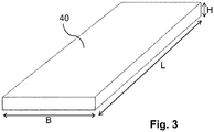
- the piezoelectric element as a thin, rectangular piezoelectric layer, preferably with a height H in the range of 100 .mu.m to 1000 .mu.m, preferably in the range of 250 .mu.m to 350 .mu.m, formed, wherein the length L, B of the side edges of the respective determine first and second resonance frequency.
- the direction in which the height of the piezoelectric layer is measured is perpendicular to the side edges L, B.
- the required / desired resonance frequencies are easily adjustable by the lengths L, B of the side edges.
- the piezoelectric layer may preferably contain lead zirconate titanate (PZT).
- the piezoelectric element has a total of at least two electrodes each layered, wherein a first electrode on the underside of the rectangular piezoelectric layer and at least one second electrode on the top of the rectangular piezoelectric layer are arranged.
- the upper surface of the piezoelectric layer is a side surface having the largest dimension of the piezoelectric layer, and the lower surface is the side of the piezoelectric layer opposite to the upper surface.
- the piezoelectric element has a total of at least three electrodes each layered, wherein a first electrode on the underside of the rectangular piezoelectric layer and a second electrode and at least one third electrode, which is galvanically isolated from the second electrode on the Top of the rectangular piezoelectric layer are arranged.
- the second electrode and the at least one third electrode may be arranged on the upper side of the piezoelectric layer next to each other, for example as a rectangular layer. This structure is particularly easy to implement.
- the electrodes arranged on the upper side have comb-like webs, wherein the webs of the second electrode and the webs of the third electrode intermesh, i. H. in each case one web of the second electrode lies in a gap between two webs of the third electrode and vice versa.
- the circuitry complexity for the simultaneous transmission and reception operation at several frequencies is simplified. This results from the fact that there is no galvanic contact between the second electrode and the third electrode on top of the piezoelectric layer, i. H. the two electrodes are electrically isolated from each other. As a result, no additional separation must be created.
- an amplifier is provided whose input is connected to its power supply via a rectifier to the piezoelectric element. With the aid of the electrical energy converted by the piezoelement at the first resonance frequency, the amplifier generates an electrical output signal (an alternating voltage), by which the piezoelement can be excited at the second resonant frequency and generates the corresponding second ultrasound signal for transmission.
- the amplifier can be designed as a class E amplifier.
- the length L, B of the side edges of the piezoelectric layer is selected such that the frequency spacing between the first resonance frequency and the second resonance frequency is at least 100 kHz, preferably at least 450 kHz. is.
- the amplifier has a modulator by means of which the output signal can be modulated for the transmission of data.
- modulation methods such as frequency, amplitude or phase modulation can be used.
- the above object is further achieved by a method for operating an implant described above, in which the piezoelectric element is excited at the first resonant frequency and receives the first ultrasonic signals emitted by the transmitting unit of the further device and is excited by the generated electrical energy at the second resonant frequency and thereby transmits the second ultrasonic signals.
- the method according to the invention has the advantages already mentioned above in connection with the implant.
- an alternating voltage is preferably generated by means of the amplifier by using the electrical energy generated by the first ultrasonic signals as an output signal, with which the piezoelectric element at the second resonant frequency can be excited.
- the modulator described above modulates the electrical output of the amplifier described above.
- the implant described is able to communicate bidirectionally with another device.
- bidirectional communication of the implant is possible both in alternating operation (half-duplex) and in counter-operation (full-duplex).
- a system of a first embodiment of an implant 10 according to the invention and a transmitting and receiving unit 30 of a further device is in the Figures 1 and 2 shown.
- the further device may be a programming device, a patient device or another implant.
- first ultrasonic signals 21 are sent, which reach the implant 10 according to the invention through the body and are received there by means of the piezoelectric element 11.
- the same piezoelectric element 11 is also used, as will be described in more detail below, as a transmitter for second ultrasonic signals 22 from the implant 10 to the transmitting and receiving unit 30 of the further device for transmitting data from the implant 10 to the further device.
- the piezoelectric element 11 of the implant according to the invention comprises an in Fig. 3 represented, plate-shaped, rectangular, ceramic piezoelectric layer 40 having a certain predetermined length L, a certain predetermined width B and a certain predetermined height H.
- the height H of the piezoelectric layer is small compared to the length L and the width B. Die Height H is, for example, 300 ⁇ m. Accordingly, the piezoelectric layer 40 is also referred to as thin.
- the resonance frequencies of the piezoelectric element 11 are predetermined by the length L and the width B of the piezoelectric layer 40.
- the course of the absolute value of the impedance as a function of the frequency of such a piezoelectric layer is in Fig. 4 shown. According to shows Fig. 5 the course of the phase dependence between current and voltage of the frequency for the same layer.
- the piezoelectric layer 40 is contacted at its top and bottom, so that the electric field lines from top to bottom or from bottom to top (corresponding to the polarity of the applied voltage) of the layer 40, and examined with the help of an impedance analyzer.
- the jumps in an impedance curve each point to a resonance at the corresponding frequency.
- a local minimum characterizes a series resonant frequency of the ceramic.
- the following local maximum characterizes the associated parallel resonance frequency.
- the piezoelectric layer 40 of the piezoelectric element 11 has, as in the FIGS. 6 to 8 illustrated, in a first embodiment, two layered running electrodes, namely on the bottom of a first, layered electrode formed 41, as in Fig. 6 shown, and on the top of a second, layered electrode 42 (see. Fig. 7 ).
- the upper side and the lower side of the piezoelectric layer 40 are opposing side surfaces having the largest extension.
- the electrodes 42, 41 occupy almost the entire surface of the upper surface and the lower surface of the piezoelectric layer 40, respectively.
- FIGS. 10 to 12 illustrated second embodiment of a piezoelectric element 11 on top of the piezoelectric layer 40, as in Fig. 10 shown, a second electrode 142 and a third electrode 143 applied in the form of two juxtaposed layers.
- On the underside is analogous to the first embodiment of a piezoelectric element 11, as in Fig. 11 shown, only a single first electrode 41 is provided.
- the second electrode 142 and the third electrode 143 are galvanically separated from each other.
- FIGS. 14 to 16 illustrated third embodiment of a piezoelectric element 11 differs from the second embodiment, as in Fig. 14 in the structure of the second electrode 242 and third electrode 243 arranged on the upper surface of the piezoelectric layer 40.
- These electrodes 242, 243 are comb-like arranged webs, wherein in each case a web of the second electrode 242 is arranged in a gap between two webs of the third electrode 243 and vice versa.
- On the underside of the piezoelectric layer 40 is, as in Fig. 15 shown, only a single electrode 41 provided analogous to the first and second embodiments.
- the second electrode 242 and the third electrode 243 are galvanically separated from each other.
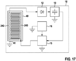
- FIGS Figures 13 and 17 The interconnection of the electrodes of the piezoelectric element 11 is in the Figures 9 . 13 and 17 each explained with reference to a block diagram.
- circuit variants there are two different circuit variants: a first circuit variant for a piezoelectric element 11 with two electrodes, as in FIG Fig. 9 and a second circuit variant for a piezoelectric element 11 with three electrodes as shown in FIGS Figures 13 and 17 shown.
- the Fig. 9 shows the first circuit variant. While the first electrode 41 is grounded, the second electrode 42 is connected to a circulator 17 which separates the frequency f1 of the incoming signal from the frequency f2 of the outgoing signal.
- the piezoelectric element receives a first ultrasonic signal 21 having a frequency f1, which is converted into a corresponding incoming electrical signal having a frequency f1.
- the circulator 17 forwards the incoming signal having the frequency f1 to a rectifier 12, for example a diode, and then supplies it to a capacitor 13, which serves as an energy buffer. At the capacitor 13, the incoming signal can be tapped.
- a generated by the frequency generator 16 and amplified by the class E amplifier 15 outgoing signal at the frequency f2 to the second electrode 42 is forwarded.
- the connection between the capacitor 13 and the class E amplifier 15 is the power supply of the amplifier.
- the piezoelectric element 11 converts the outgoing electrical signal into the second ultrasonic signal 22.
- an unillustrated modulator is provided, which modulates the outgoing signal by means of a frequency, amplitude or phase modulation to transmit data from the implant 10 to the other device.
- Fig. 13 the interconnection of the electrodes 41, 142 and 143 and Fig. 17 the interconnection of the electrodes 41, 242 and 243 according to the second circuit variant.
- the first electrode 41 is grounded.
- the second electrode 142, 242 is connected to the rectifier 12, which rectifies an incoming electrical signal generated from the first ultrasonic signal 21 at the frequency f1.
- the rectified signal is fed to a capacitor 13, which serves as an energy store.
- the incoming signal in the form of the frequency f1 can be tapped.
- the third electrode 143, 243 is connected to the Class E amplifier 15, respectively, and is provided for generating the second ultrasonic signal 22 and transmitting the second ultrasonic signal 22 at the frequency f2, which is electrically connected to the third electrode 143, 243, respectively Frequency generator 16 was provided and amplified by the class E amplifier 15.
- the connection between the capacitor 13 and the class E amplifier 15 is the power supply of the amplifier.
- an unillustrated modulator is provided, which modulates the outgoing signal by means of a frequency, amplitude or phase modulation to transmit data from the implant 10 to the other device.
- the transmitting and receiving unit 30 of the further device sends a first ultrasonic signal 21 by means of a transceiver 31, for example at a frequency f1 of 320 kHz.
- This first ultrasonic signal corresponds to the series resonance frequency of the piezoelectric element 11 of the implant 10 and is therefore received particularly efficiently by the piezoelectric element 11 and converted into a corresponding electrical alternating voltage.
- This electrical alternating voltage is rectified by means of a rectifier 12, which is connected to the piezoelectric element 11, and intermediately stored in a capacitor 13 connected to the rectifier 12.
- the stored in the capacitor 13 electrical energy in the form of a DC voltage is then converted by means of a class E amplifier 15 and an oscillator 16 in an AC voltage with a frequency of 800 kHz.
- the pending for transmission data are modulated by means of a known modulation method with a built-in class E amplifier 15 modulator and the piezoelectric element 11 at the second series resonant frequency f2 in a second ultrasonic signal 22 is converted.
- This conversion of the electrical energy into mechanical energy is carried out particularly efficiently by the piezoelement 11, since it is operated at the second series resonance frequency f2.
- the second ultrasonic signal 22 is received by means of transceiver 31, rectified and demodulated.
- a high-pass filter 33, amplifier 34 and a demodulator 35 connected thereto are provided.
- the transmitted data is extracted from the second ultrasonic signal 22.
- an unillustrated memory may be provided for the data transmitted with the second ultrasonic signal 22, as well as an arithmetic unit (not shown) (microcontroller, ⁇ C) for processing this data.
- the transmitting and receiving unit 30 of the further device is constructed substantially analogously to the implant. However, it preferably has at least two sound transducers provided in a sound converter unit 31, a first sound transducer for generating and transmitting the first ultrasonic signal 21 and a second sound transducer for receiving and converting the second ultrasonic signal 22.
- a construction of the transmitting and receiving unit 30 of the further device is therefore advantageous because the separation of the processes sending the first ultrasonic signal 21 and receiving the second ultrasonic signal 22 by at least two different transducers, the complexity of the signal processing is reduced.
- the transmitting and receiving unit 30 of the other device analogous to the implant 10, with a combined sound transducer according to the FIGS. 6 to 8 . 10 to 12 and 14 to 16 being constructed.
- This variant can be advantageous if the further device is also an implant.
- the implant 10 according to the invention can be designed to save space, since only due to the energy transmitted with the ultrasound signal, in particular in applications with extensive communication, the voltage source can be realized stii classroomder.
- the ultrasonic signals used for data transmission have a high range in the body of a person.
- the elements of the implant according to the invention can be in a metallic housing, for. B. of titanium, are integrated.
Abstract
Die vorliegende Erfindung betrifft ein Implantat (10) mit einem Empfänger für von einer externen Sendeeinheit eines weiteren Geräts ausgesandte erste Ultraschallsignale (21) in Form eines Piezoelements (11), welches durch die ersten Ultraschallsignale (21) bei einer ersten Resonanzfrequenz (f1) angeregt wird und hierbei die mit den ersten Ultraschallsignalen (21) übertragene mechanische Energie in elektrische Energie wandelt. Eine weitere Miniaturisierung des Implantats kann dadurch erreicht werden, dass das Piezoelement (11) zusätzlich bei einer zweiten Resonanzfrequenz (f2) anregbar ist, welche sich von der ersten Resonanzfrequenz (f1) unterscheidet, und bei der zweiten Resonanzfrequenz (f2) als Sender von zweiten Ultraschallsignalen (22) betreibbar ist. Es wird ferner ein Verfahren zum Betreiben eines derartigen Implantats (10) beschrieben.

Description
Die Erfindung betrifft ein medizinisches Implantat sowie ein Verfahren zum Betreiben desselben.The invention relates to a medical implant and a method for operating the same.
Medizinische Endoprothesen oder Implantate für die unterschiedlichsten Anwendungen sind in großer Vielfalt aus dem Stand der Technik bekannt. Implantate werden unterteilt in passive und aktive Implantate. Passive Implantate erfüllen eher mechanische Aufgaben im Körper, in den sie eingesetzt sind. Passive Implantate sind beispielsweise ein Stent, ein Herzklappenersatz, ein Brustimplantat, Prothesen von Körpergliedern oder optische Linsen. Demgegenüber beinhalten aktive Implantate eine Elektronik und sind in der Lage, bestimmte Körperzustände zu detektieren oder eine Behandlung vorzunehmen. Beispiele für aktive Implantate sind Herzschrittmacher, Neurostimulatoren, Medikamentenpumpen oder Defibrillatoren. Weitere Anwendungen aktiver Implantate umfassen auch Sensoren für Körperfunktionen, beispielsweise Drucksensoren wie sie in der Druckschrift
Bei der Verwendung von aktiven Implantaten ist es erforderlich, Daten, die die Steuerung des Implantats betreffen oder die von dem Implantat erzeugt wurden, z. B. Messdaten eines in das Implantat integrierten Sensors, mit einer bezüglich des Implantats externen Einheit auszutauschen. Bei einer solchen, bezüglich des Implantats externen Einheit kann es sich beispielsweise um eine körperexterne Einheit wie z. B. um ein Programmiergerät oder um ein weiteres Implantat handeln. Zur Vereinfachung der Darstellung wird im Folgenden eine vorgenannte körperexterne Einheit oder ein weiteres Implantat als weiteres Gerät bezeichnet. Es ist insbesondere gewünscht, dass ein Datenaustausch mit dem weiteren Gerät drahtlos erfolgt. Zudem sollen die Implantate möglichst klein sein, um den Körper aufgrund ihres Raumbedarfs möglichst wenig zu belasten.When using active implants, it is necessary to provide data related to the control of the implant or generated by the implant, e.g. B. measurement data of a sensor integrated in the implant, with an external implant with respect to the implant. In such, with respect to the implant external unit may be, for example, a body-external unit such. B. may be a programmer or another implant. To simplify the illustration, an abovementioned entity external to the body or another implant will be referred to as a further device in the following. It is particularly desirable that a data exchange with the other Device is wireless. In addition, the implants should be as small as possible to burden the body due to their space requirements as little as possible.
In bekannten Implantaten werden vorrangig galvanische Kommunikation/ impedanzmodulationsbasierte Kommunikation, induktive Nahfeldtelemetrie- oder Funksysteme zur Datenübertragung zwischen dem Implantat und einem körperexternen Gerät zur Datenerfassung und/oder Datenverarbeitung eingesetzt. Die bekannten Systeme haben jedoch eine Reihe von Nachteilen. Im Fall der galvanischen Kommunikation/ impedanzmodulationsbasierten Kommunikation sind Gehäusedurchführungen bzw. Elektroden an der Gehäuseaußenseite erforderlich. Zudem müssen auf der Seite des körperexternen Gerätes Elektroden auf der Körperoberfläche aufgeklebt werden, was bei einer häufigen Verwendung der Schnittstelle nur begrenzt praxistauglich ist. Die induktive Nahfeldtelemetrie besitzt einen stark eingeschränkten Übertragungsradius, insbesondere bei der Miniaturisierung von Implantaten und der damit verbundenen Verwendung von kleinen Spulen. In Bezug auf eine Funkübertragung von Daten besteht der bekannte Nachteil, dass die Antenne eine gewisse Größe aufweisen muss, was eine weitere Miniaturisierung verhindert. Zudem ist es nicht möglich, die Antenne in ein Gehäuse aus leitfähigem Material, wie beispielsweise Titan, zu platzieren, sodass die Integration einer Antenne in ein Implantat mit größerem Aufwand verbunden ist. Ein weiterer bekannter Nachteil bei der Funkübertragung von Daten besteht darin, dass der Energiebedarf für die Datenübertragung in Abhängigkeit von der Implantationstiefe des Implantats im Körper steigt. Dies führt zwangsläufig zum Einsatz größerer Energiequellen, was ebenfalls einer weiteren Miniaturisierung entgegensteht.In known implants, galvanic communication / impedance modulation-based communication, inductive Nahfeldtelemetrie- or radio systems for data transmission between the implant and an off-field device for data acquisition and / or data processing are used primarily. However, the known systems have a number of disadvantages. In the case of galvanic communication / impedance modulation-based communication, housing feedthroughs or electrodes on the outside of the housing are required. In addition, on the side of the body-external device, electrodes must be glued to the body surface, which is only practicable with frequent use of the interface. Inductive Near Field Telemetry has a very limited transmission radius, especially in the miniaturization of implants and the associated use of small coils. With regard to a radio transmission of data, the known disadvantage is that the antenna must have a certain size, which prevents further miniaturization. In addition, it is not possible to place the antenna in a housing made of conductive material, such as titanium, so that the integration of an antenna in an implant is associated with greater effort. Another known disadvantage in the radio transmission of data is that the energy required for data transmission increases depending on the implantation depth of the implant in the body. This inevitably leads to the use of larger energy sources, which also precludes further miniaturization.
Auch Ultraschall wurde bereits zum Austausch von Daten mit einem Implantat verwendet. Die bisher vorgeschlagenen Systeme sind jedoch technologisch aufwändig und sehr platzintensiv. Beispiele für die Verwendung von Ultraschall zur Datenübertragung sind in den Druckschriften "
In der Druckschrift
Folglich besteht die Aufgabe der vorliegenden Erfindung darin, ein Implantat mit der Möglichkeit der drahtlosen Datenübertragung zu schaffen, das einfach aufgebaut ist und eine weitere Miniaturisierung erlaubt.Consequently, the object of the present invention is to provide an implant with the possibility of wireless data transmission, which is simple in construction and allows further miniaturization.
Die obige Aufgabenstellung wird gelöst durch ein Implantat mit den in Anspruch 1 angegebenen Merkmalen. Insbesondere besitzt das erfindungsgemäße Implantat nicht nur einen Empfänger für von einer Sendeeinheit eines weiteren Geräts ausgesandte erste Ultraschallsignale in Form eines Piezoelements, welches durch die ersten Ultraschallsignale bei einer ersten Resonanzfrequenz angeregt wird und hierbei die mit den ersten Ultraschallsignalen übertragene mechanische Energie in elektrische Energie wandelt. Dieses Piezoelement ist zusätzlich bei einer zweiten Resonanzfrequenz anregbar, wobei sich die zweite Resonanzfrequenz von der ersten Resonanzfrequenz unterscheidet, und bei der zweiten Resonanzfrequenz als Sender von zweiten Ultraschallsignalen betreibbar.The above problem is solved by an implant having the features specified in claim 1. In particular, the implant according to the invention not only has a receiver for first ultrasonic signals emitted by a transmitting unit of another device in the form of a piezo element, which is excited by the first ultrasonic signals at a first resonant frequency and in this case converts the mechanical energy transmitted with the first ultrasonic signals into electrical energy. This piezo element is additionally excitable at a second resonant frequency, the second resonant frequency being different from the first resonant frequency, and operable as a transmitter of second ultrasonic signals at the second resonant frequency.
Das erfindungsgemäße Implantat hat den Vorteil, dass für das Empfangen der ersten Ultraschallsignale und das Senden der zweiten Ultraschallsignale ein und dasselbe Piezoelement verwendet wird und dieses damit als Transceiver betrieben wird. Hierdurch ist nur ein geringer technologischer Aufwand für das Senden der ersten Ultraschallsignale und das Empfangen der zweiten Ultraschallsignale erforderlich. Zudem wird das Piezoelement beim Senden und Empfangen der Ultraschallsignale im Resonanzmodus betrieben, so dass eine effektive Energiewandlung erfolgen kann. Für einen Betrieb im Resonanzmodus können als Resonanzfrequenz beim Senden und beim Empfangen sowohl die Serienresonanzfrequenz als auch die Parallelresonanzfrequenz genutzt werden. Aus Gründen der Energieeffizienz ist es jedoch vorteilhaft, beim Senden und beim Empfangen der Ultraschallsignale, die Serienresonanzfrequenz zu nutzen.The implant according to the invention has the advantage that one and the same piezoelectric element is used for receiving the first ultrasonic signals and transmitting the second ultrasonic signals, and this is thus operated as a transceiver. As a result, only a small technological effort for transmitting the first ultrasonic signals and receiving the second ultrasonic signals is required. In addition, the piezoelectric element is operated during transmission and reception of the ultrasonic signals in resonance mode, so that an effective energy conversion can take place. For resonance mode operation, both the series resonant frequency and the parallel resonant frequency can be used as the resonant frequency during transmission and reception. Out For reasons of energy efficiency, however, it is advantageous to use the series resonance frequency when transmitting and receiving the ultrasonic signals.
Das Piezoelement erzeugt durch das Umwandeln der empfangenen ersten Ultraschallsignale ausreichend elektrische Energie, um bei der zweiten Resonanzfrequenz zweite Ultraschallsignale zu erzeugen und zu versenden. Erfindungsgemäß wurde demnach für das aktive Implantat ein passives Kommunikationsverfahren realisiert, bei dem die von den ersten Ultraschallsignalen umgewandelte elektrische Energie genutzt wird, um damit das Piezoelement bei der zweiten Resonanzfrequenz zum Schwingen anzuregen, wodurch das Piezoelement Ultraschall abgibt, der mittels eines weiteren Geräts empfangen werden kann. Das erfindungsgemäße Implantat kann in einem Fall ohne zusätzliche Energiequelle betrieben werden. In diesem Fall ist eine erhebliche Raumersparnis und entsprechende Miniaturisierung des Implantats möglich. In einem anderen Fall kann das Implantat mit einer Energiequelle betrieben werden. Dabei kann mit dem erfindungsgemäßen Implantat eine Energieeinsparung insbesondere bei häufig kommunizierenden Anwendungen erzielt werden, so dass eine deutliche Verlängerung der Lebensdauer des Implantats und/oder Reduzierung der Baugröße der Energiequelle des Implantats und damit eine Reduzierung der Baugröße des Implantats erreicht werden kann.By converting the received first ultrasonic signals, the piezoelectric element generates sufficient electrical energy to generate and send second ultrasonic signals at the second resonance frequency. According to the invention, therefore, a passive communication method has been realized for the active implant in which the electrical energy converted by the first ultrasound signals is used in order to cause the piezoelement to vibrate at the second resonant frequency, whereby the piezo element emits ultrasound which is received by another device can. The implant according to the invention can be operated in one case without additional energy source. In this case, a considerable space savings and corresponding miniaturization of the implant is possible. In another case, the implant can be operated with a power source. In this case, with the implant according to the invention, an energy saving can be achieved, in particular for frequently communicating applications, so that a significant extension of the life of the implant and / or reduction of the size of the energy source of the implant and thus a reduction of the size of the implant can be achieved.
Im Zusammenhang mit der Übertragung von Ultraschallsignalen ist auch die Verwendung eines metallischen Gehäuses für das Implantat unproblematisch.In connection with the transmission of ultrasonic signals, the use of a metallic housing for the implant is unproblematic.
Gegenüber nicht-ultraschallbasierten Datenübertragungsverfahren ergibt sich somit durch die erfindungsgemäße Lösung ein deutlicher Vorteil im Hinblick auf eine bessere Integrierbarkeit und Miniaturisierung. Zudem lassen sich Schallwandler in Form von Piezoelementen leicht in hermetisch abgeschlossene und miniaturisierte Gehäuse integrieren.Compared with non-ultrasound-based data transmission methods, the solution according to the invention therefore provides a clear advantage with regard to better integration and miniaturization. In addition, transducers in the form of piezoelectric elements can be easily integrated into hermetically sealed and miniaturized housings.
Weiter ist vorteilhaft, dass mit dem erfindungsgemäßen Implantat auch eine Kommunikation zwischen zwei oder mehr Implantaten in einem Netzwerk realisiert werden kann. Hierbei wird z. B. ein erstes Implantat als weiteres Gerät und damit als Ultraschallsender und/oder -empfänger und/oder zur Datenverarbeitung und/oder -speicherung verwendet und weist hierfür einen kleinen Energiespeicher, beispielsweise eine kleine Batterie, auf. Das zweite Implantat hat den erfindungsgemäßen, unten im Detail beschriebenen Aufbau und kommuniziert passiv. Das erfindungsgemäße Implantat kann dabei insbesondere dort eingesetzt werden, wo nur sehr wenig Raum zum Einbringen des Implantats zur Verfügung steht, beispielsweise an einer bestimmten Messstelle für einen Körperparameter. Das erfindungsgemäße Implantat stellt somit einen Knoten in einem Netzwerk von miteinander kommunizierenden Implantaten oder von externen Geräten und Implantaten dar.It is also advantageous that with the implant according to the invention also a communication between two or more implants in a network can be realized. This z. B. a first implant as another device and thus as an ultrasonic transmitter and / or receiver and / or used for data processing and / or storage and has for this purpose a small energy storage, such as a small battery on. The second implant has the construction according to the invention described in detail below and communicates passively. The implant according to the invention can be used in particular where only very little space is available for introducing the implant, for example at a specific measuring point for a body parameter. The implant according to the invention thus represents a node in a network of implants communicating with one another or of external devices and implants.
Nach der vorliegenden Erfindung besonders hervorzuheben ist, dass das Piezoelement gleichzeitig bei der ersten Resonanzfrequenz und der zweiten Resonanzfrequenz anregbar ist. Hierdurch ist die erfindungsgemäße Vorrichtung auch hinsichtlich ihrer Schnelligkeit vorteilhaft.Particularly noteworthy according to the present invention is that the piezoelectric element can be excited simultaneously at the first resonance frequency and the second resonance frequency. As a result, the device according to the invention is also advantageous in terms of their speed.
In einem bevorzugten Ausführungsbeispiel ist das Piezoelement als dünne, rechteckförmige piezoelektrische Schicht, vorzugsweise mit einer Höhe H im Bereich von 100 µm bis 1000 µm, vorzugsweise im Bereich von 250 µm bis 350 µm, ausgebildet, wobei die Länge L, B der Seitenkanten die jeweilige erste und zweite Resonanzfrequenz bestimmen. Hierbei verläuft die Richtung, in die die Höhe der piezoelektrischen Schicht gemessen wird, senkrecht zu den Seitenkanten L, B. Die erforderlichen/gewünschten Resonanzfrequenzen sind durch die Längen L, B der Seitenkanten einfach einstellbar. Die piezoelektrische Schicht kann vorzugsweise Blei-Zirkonat-Titanat (PZT) enthalten.In a preferred embodiment, the piezoelectric element as a thin, rectangular piezoelectric layer, preferably with a height H in the range of 100 .mu.m to 1000 .mu.m, preferably in the range of 250 .mu.m to 350 .mu.m, formed, wherein the length L, B of the side edges of the respective determine first and second resonance frequency. Here, the direction in which the height of the piezoelectric layer is measured is perpendicular to the side edges L, B. The required / desired resonance frequencies are easily adjustable by the lengths L, B of the side edges. The piezoelectric layer may preferably contain lead zirconate titanate (PZT).
In einer Weiterbildung der Erfindung weist das Piezoelement insgesamt mindestens zwei jeweils schichtartig ausgebildete Elektroden auf, wobei eine erste Elektrode auf der Unterseite der rechteckförmigen piezoelektrischen Schicht und mindestens eine zweite Elektrode auf der Oberseite der rechteckförmigen piezoelektrischen Schicht angeordnet sind. Hierbei ist die Oberseite der piezoelektrischen Schicht eine Seitenfläche mit der größten Ausdehnung der piezoelektrischen Schicht und die Unterseite die der Oberseite gegenüberliegende Seite der piezoelektrischen Schicht.In a further development of the invention, the piezoelectric element has a total of at least two electrodes each layered, wherein a first electrode on the underside of the rectangular piezoelectric layer and at least one second electrode on the top of the rectangular piezoelectric layer are arranged. Here, the upper surface of the piezoelectric layer is a side surface having the largest dimension of the piezoelectric layer, and the lower surface is the side of the piezoelectric layer opposite to the upper surface.
In einer bevorzugten Weiterbildung der Erfindung weist das Piezoelement insgesamt mindestens drei jeweils schichtartig ausgebildete Elektroden auf, wobei eine erste Elektrode auf der Unterseite der rechteckförmigen piezoelektrischen Schicht und eine zweite Elektrode und mindestens eine dritte Elektrode, welche galvanisch von der zweiten Elektrode getrennt ist, auf der Oberseite der rechteckförmigen piezoelektrischen Schicht angeordnet sind.In a preferred embodiment of the invention, the piezoelectric element has a total of at least three electrodes each layered, wherein a first electrode on the underside of the rectangular piezoelectric layer and a second electrode and at least one third electrode, which is galvanically isolated from the second electrode on the Top of the rectangular piezoelectric layer are arranged.
In einem Ausführungsbeispiel können die zweite Elektrode und die mindestens eine dritte Elektrode auf der Oberseite der piezoelektrischen Schicht nebeneinander, beispielsweise als rechteckförmige Schicht, angeordnet sein. Dieser Aufbau ist besonders einfach realisierbar.In one embodiment, the second electrode and the at least one third electrode may be arranged on the upper side of the piezoelectric layer next to each other, for example as a rectangular layer. This structure is particularly easy to implement.
Besonders bevorzugt ist es, wenn die auf der Oberseite angeordneten Elektroden kammartig ausgebildete Stege aufweisen, wobei die Stege der zweiten Elektrode und die Stege der dritten Elektrode ineinander greifen, d. h. je ein Steg der zweiten Elektrode liegt in einer Lücke zwischen zwei Stegen der dritten Elektrode und umgekehrt.It is particularly preferred if the electrodes arranged on the upper side have comb-like webs, wherein the webs of the second electrode and the webs of the third electrode intermesh, i. H. in each case one web of the second electrode lies in a gap between two webs of the third electrode and vice versa.
Durch eine Anordnung der zweiten Elektrode und der dritten Elektrode auf der Oberseite der piezoelektrischen Schicht vereinfacht sich der schaltungstechnische Aufwand für den gleichzeitigen Sende- und Empfangsbetrieb bei mehreren Frequenzen. Dies ergibt sich daraus, dass kein galvanischer Kontakt zwischen der zweiten Elektrode und der dritten Elektrode auf der Oberseite der piezoelektrischen Schicht besteht, d. h. die beiden Elektroden sind voneinander elektrisch isoliert. Dadurch muss keine zusätzliche Trennung geschaffen werden.By arranging the second electrode and the third electrode on the upper side of the piezoelectric layer, the circuitry complexity for the simultaneous transmission and reception operation at several frequencies is simplified. This results from the fact that there is no galvanic contact between the second electrode and the third electrode on top of the piezoelectric layer, i. H. the two electrodes are electrically isolated from each other. As a result, no additional separation must be created.
Es ist von Vorteil, wenn ein Verstärker vorgesehen ist, dessen Eingang zu seiner Energieversorgung über einen Gleichrichter mit dem Piezoelement verbunden ist. Mithilfe der bei der ersten Resonanzfrequenz durch das Piezoelement gewandelten elektrischen Energie erzeugt der Verstärker ein elektrisches Ausgangssignal (eine Wechselspannung), durch das das Piezoelement bei der zweiten Resonanzfrequenz anregbar ist und das entsprechende zweite Ultraschallsignal zum Versenden erzeugt. Beispielsweise kann der Verstärker als Klasse-E-Verstärker ausgeführt sein.It is advantageous if an amplifier is provided whose input is connected to its power supply via a rectifier to the piezoelectric element. With the aid of the electrical energy converted by the piezoelement at the first resonance frequency, the amplifier generates an electrical output signal (an alternating voltage), by which the piezoelement can be excited at the second resonant frequency and generates the corresponding second ultrasound signal for transmission. For example, the amplifier can be designed as a class E amplifier.
Bei einer Verwendung von lediglich einer einzigen Elektrode auf der Oberseite der piezoelektrischen Schicht und einer einzigen Elektrode auf der Unterseite der piezoelektrischen Schicht würden die Elektroden auf der Ober- und Unterseite des Piezoelements durch den Klasse-E-Verstärker kurzgeschlossen werden, was durch die zusätzliche Verwendung eines Zirkulators oder eines Diplexers behoben werden kann. Durch die vorgeschlagene Strukturierung der Elektroden auf der Oberseite der piezoelektrischen Schicht kann eine solche Trennung und somit der damit verbundene schaltungstechnische Aufwand vermieden werden.Using only a single electrode on top of the piezoelectric layer and a single electrode on the bottom of the piezoelectric layer would short the electrodes on the top and bottom of the piezo element through the class E amplifier, due to the additional use a circulator or a diplexer can be solved. The proposed patterning of the electrodes on the upper side of the piezoelectric layer can avoid such a separation and thus the associated circuit complexity.
Um eine gute Trennung der Anregung des Piezoelements im Sende- und Empfangsmodus zu erzielen, ist die Länge L, B der Seitenkanten der piezoelektrischen Schicht so gewählt, dass der Frequenzabstand zwischen der ersten Resonanzfrequenz und der zweiten Resonanzfrequenz mindestens 100 kHz, vorzugsweise mindestens 450 kHz, beträgt.In order to achieve a good separation of the excitation of the piezoelectric element in the transmission and reception mode, the length L, B of the side edges of the piezoelectric layer is selected such that the frequency spacing between the first resonance frequency and the second resonance frequency is at least 100 kHz, preferably at least 450 kHz. is.
Um eine Übertragung von Daten von dem Implantat zu einem weiteren Gerät, beispielsweise einem externen Empfänger oder einem weiteren Implantat, zu realisieren, ist es von Vorteil, wenn der Verstärker einen Modulator aufweist, durch den das Ausgangssignal zur Übertragung von Daten modulierbar ist. Hierfür können alle gängigen Modulationsverfahren wie Frequenz-, Amplituden- oder Phasenmodulation verwendet werden.In order to realize a transfer of data from the implant to another device, for example an external receiver or a further implant, it is advantageous if the amplifier has a modulator by means of which the output signal can be modulated for the transmission of data. For this purpose, all common modulation methods such as frequency, amplitude or phase modulation can be used.
Die obige Aufgabe wird ferner durch ein Verfahren zum Betreiben eines oben beschriebenen Implantats gelöst, bei dem das Piezoelement bei der ersten Resonanzfrequenz angeregt wird und die von der Sendeeinheit des weiteren Geräts ausgesandten ersten Ultraschallsignale empfängt sowie mittels der erzeugten elektrischen Energie bei der zweiten Resonanzfrequenz angeregt wird und hierdurch die zweiten Ultraschallsignale aussendet. Das erfindungsgemäße Verfahren besitzt die oben bereits im Zusammenhang mit dem Implantat genannten Vorteile. Hierfür wird vorzugsweise mittels des Verstärkers unter Einsatz der durch die ersten Ultraschallsignale erzeugten elektrischen Energie eine Wechselspannung als Ausgangssignal erzeugt, mit der das Piezoelement bei der zweiten Resonanzfrequenz anregbar ist.The above object is further achieved by a method for operating an implant described above, in which the piezoelectric element is excited at the first resonant frequency and receives the first ultrasonic signals emitted by the transmitting unit of the further device and is excited by the generated electrical energy at the second resonant frequency and thereby transmits the second ultrasonic signals. The method according to the invention has the advantages already mentioned above in connection with the implant. For this purpose, an alternating voltage is preferably generated by means of the amplifier by using the electrical energy generated by the first ultrasonic signals as an output signal, with which the piezoelectric element at the second resonant frequency can be excited.
In einem besonders bevorzugten Ausführungsbeispiel moduliert der oben beschriebene Modulator das elektrische Ausgangssignal des oben beschriebenen Verstärkers.In a particularly preferred embodiment, the modulator described above modulates the electrical output of the amplifier described above.
Mit einer entsprechenden Modulation können auch mittels des zu dem Implantat ausgesandten ersten Ultraschallsignals Daten zu dem Implantat übertragen werden. Damit ist das beschriebene Implantat in der Lage bidirektional mit einem weiteren Gerät zu kommunizieren. Mit dem beschriebenen Piezoelement ist eine bidirektionale Kommunikation des Implantats sowohl im Wechselbetrieb (halbduplex) als auch im Gegenbetrieb (vollduplex) möglich.With a corresponding modulation, data can also be transmitted to the implant by means of the first ultrasound signal emitted to the implant. Thus, the implant described is able to communicate bidirectionally with another device. With the piezo element described, bidirectional communication of the implant is possible both in alternating operation (half-duplex) and in counter-operation (full-duplex).
Das erfindungsgemäße Implantat und das erfindungsgemäße Verfahren werden nachfolgend anhand von Beispielen und Figuren erläutert. Dabei bilden alle abgebildeten und/oder beschriebenen Merkmale den Gegenstand der Erfindung, auch unabhängig von ihrer Zusammenfassung in den Ansprüchen oder deren Rückbeziehung.The implant according to the invention and the method according to the invention are explained below with reference to examples and figures. All mapped and / or described features form the subject matter of the invention, regardless of their combination in the claims or their dependency.
Es zeigen schematisch:
- Fig. 1
- ein erstes Ausführungsbeispiel eines erfindungsgemäßen Implantats sowie eine externe Sende- und Empfangseinheit als Blockschaltbild,
- Fig. 2
- das Ausführungsbeispiel eines Implantats gemäß
Fig. 1 sowie die dort gezeigte Sende- und Empfangseinheit im Detail als Blockschaltbild, - Fig. 3
- eine piezoelektrische Schicht in einer perspektivischen Ansicht von der Seite,
- Fig. 4
- den Impedanzverlauf (in Abhängigkeit von der Frequenz) eines Piezoelements eines erfindungsgemäßen Implantats nach
Fig. 1 , - Fig. 5
- den Phasenverlauf eines Piezoelements eines erfindungsgemäßen Implantats nach
Fig. 1 , - Fig. 6
- ein erstes Ausführungsbeispiel eines Piezoelements für ein erfindungsgemäßes Implantat in einer Ansicht von unten,
- Fig. 7
- das Piezoelement gemäß
Fig. 6 in einer Ansicht von oben, - Fig. 8
- das Piezoelement gemäß
Fig. 6 in einer Ansicht von der Seite, - Fig. 9
- ein erstes Ausführungsbeispiel eines erfindungsgemäßen Implantats mit einem in den
Fig. 6 bis 8 dargestellten Piezoelement in einem Blockschaltbild - Fig. 10
- ein zweites Ausführungsbeispiel eines Piezoelements für ein erfindungsgemäßes Implantat in einer Ansicht von oben,
- Fig. 11
- das Piezoelement gemäß
Fig. 10 in einer Ansicht von unten, - Fig. 12
- das Piezoelement gemäß
Fig. 10 in einer Ansicht von der Seite, - Fig. 13
- ein zweites Ausführungsbeispiel eines erfindungsgemäßen Implantats mit einem in den
Fig. 10 dargestellten Piezoelement in einem Blockschaltbild,bis 12 - Fig. 14
- ein drittes Ausführungsbeispiel eines Piezoelements für ein erfindungsgemäßes Implantat in einer Ansicht von oben,
- Fig. 15
- das Piezoelement gemäß
Fig. 14 in einer Ansicht von unten, - Fig. 16
- das Piezoelement gemäß
Fig. 14 in einer Ansicht von der (kürzeren) Seite und - Fig. 17
- ein drittes Ausführungsbeispiel eines erfindungsgemäßen Implantats mit einem in den
Fig. 14 dargestellten Piezoelement in einem Blockschaltbild.bis 16
- Fig. 1
- A first embodiment of an implant according to the invention and an external transmitting and receiving unit as a block diagram,
- Fig. 2
- the embodiment of an implant according to
Fig. 1 as well as the transmitting and receiving unit shown there in detail as a block diagram, - Fig. 3
- a piezoelectric layer in a perspective view from the side,
- Fig. 4
- the impedance curve (as a function of the frequency) of a piezoelectric element of an implant according to the invention
Fig. 1 . - Fig. 5
- the phase curve of a piezoelectric element of an implant according to the invention
Fig. 1 . - Fig. 6
- a first embodiment of a piezoelectric element for an implant according to the invention in a view from below,
- Fig. 7
- the piezoelectric element according to
Fig. 6 in a view from above, - Fig. 8
- the piezoelectric element according to
Fig. 6 in a view from the side, - Fig. 9
- a first embodiment of an implant according to the invention with a in the
Fig. 6 to 8 shown piezoelectric element in a block diagram - Fig. 10
- A second embodiment of a piezoelectric element for an implant according to the invention in a view from above,
- Fig. 11
- the piezoelectric element according to
Fig. 10 in a view from below, - Fig. 12
- the piezoelectric element according to
Fig. 10 in a view from the side, - Fig. 13
- A second embodiment of an implant according to the invention with a in the
10 to 12 shown piezoelectric element in a block diagram, - Fig. 14
- A third embodiment of a piezoelectric element for an implant according to the invention in a view from above,
- Fig. 15
- the piezoelectric element according to
Fig. 14 in a view from below, - Fig. 16
- the piezoelectric element according to
Fig. 14 in a view from the (shorter) side and - Fig. 17
- a third embodiment of an implant according to the invention with a in the
Fig. 14 to 16 shown piezoelectric element in a block diagram.
Ein System aus einem ersten Ausführungsbeispiel eines erfindungsgemäßen Implantats 10 und einer Sende- und Empfangseinheit 30 eines weiteren Geräts (nicht abgebildet) ist in den
Das Piezoelement 11 des erfindungsgemäßen Implantats umfasst eine in
Die Resonanzfrequenzen des Piezoelements 11 werden durch die Länge L und die Breite B der piezoelektrischen Schicht 40 vorgegeben. Durch Anregung der piezoelektrischen Schicht 40 bei den Serienresonanzfrequenzen kann besonders effizient mechanische in elektrische Energie und umgekehrt gewandelt werden.The resonance frequencies of the
Beispielsweise weist eine piezoelektrische Schicht 40 mit einer Länge L von 5 mm, einer Breite B von 2 mm und einer Höhe H von 300 µm aus dem Material Blei-Zirkonat-Titanat (PZT) eine Serienresonanzfrequenz von f1 = 320 kHz (X-Mode) und eine Serienresonanzfrequenz von f2 = 800 kHz (Y-Mode) auf. Der Verlauf des Absolutbetrags der Impedanz in Abhängigkeit von der Frequenz einer derartigen piezoelektrischen Schicht ist in
Die piezoelektrische Schicht 40 des Piezoelements 11 weist, wie in den
Demgegenüber ist bei dem in den
Das in den
Die Verschaltung der Elektroden des Piezoelements 11 ist in den
Die
Weiterhin zeigt
Die Sende- und Empfangseinheit 30 des weiteren Geräts , beispielsweise ein außerhalb des Körpers befindliches Patientengerät, sendet mittels eines Sende-/Empfangsschallwandlers 31 ein erstes Ultraschallsignal 21, beispielsweise bei einer Frequenz f1 von 320 kHz. Dieses erste Ultraschallsignal entspricht der Serienresonanzfrequenz des Piezoelements 11 des Implantats 10 und wird daher besonders effizient von dem Piezoelement 11 empfangen und in eine entsprechende elektrische Wechselspannung gewandelt. Diese elektrische Wechselspannung wird mittels eines Gleichrichters 12, der mit dem Piezoelement 11 verbunden ist, gleich gerichtet und in einem mit dem Gleichrichter 12 verbundenen Kondensator 13 zwischengespeichert. Die in dem Kondensator 13 gespeicherte elektrische Energie in Form einer Gleichspannung wird nun mittels eines Klasse-E-Verstärkers 15 und einem Oszillator 16 in eine Wechselspannung mit einer Frequenz von 800 kHz gewandelt. Die zur Übertragung anstehenden Daten werden mittels eines bekannten Modulationsverfahrens mit einem in den Klasse-E-Verstärker 15 integrierten Modulator aufmoduliert und über das Piezoelement 11 bei der zweiten Serienresonanzfrequenz f2 in ein zweites Ultraschallsignal 22 gewandelt. Diese Wandlung der elektrischen Energie in mechanische Energie erfolgt durch das Piezoelement 11 besonders effizient, da es bei der zweiten Serienresonanzfrequenz f2 betrieben wird. In der Sende- und Empfangseinheit 30 des weiteren Geräts wird das zweite Ultraschallsignal 22 mittels Sende-/Empfangsschallwandler 31 empfangen, gleichgerichtet und demoduliert. Hierfür sind ein Hochpassfilter 33, Verstärker 34 und ein damit verbundener Demodulator 35 vorgesehen. Hierdurch werden die übertragenen Daten aus dem zweiten Ultraschallsignal 22 extrahiert. Weiter kann ein nicht dargestellter Speicher für die mit dem zweiten Ultraschallsignal 22 übertragenen Daten sowie eine nicht dargestellte Recheneinheit (Mikrocontroller, µC) zur Verarbeitung dieser Daten vorgesehen sein.The transmitting and receiving
Die Sende- und Empfangseinheit 30 des weiteren Geräts ist im Wesentlichen analog zum Implantat aufgebaut. Es besitzt jedoch vorzugsweise mindestens zwei in einer Schallwandlereinheit 31 vorgesehene Schallwandler, einen ersten Schallwandler zum Erzeugen und Senden des ersten Ultraschallsignals 21 und einen zweiten Schallwandler zum Empfangen und Umwandeln des zweiten Ultraschallsignals 22. Ein derartiger Aufbau der Sende- und Empfangseinheit 30 des weiteren Geräts ist deshalb von Vorteil, weil durch die Trennung der Vorgänge Senden des ersten Ultraschallsignals 21 und Empfangen des zweiten Ultraschallsignals 22 durch mindestens zwei verschiedene Schallwandler die Komplexität der Signalverarbeitung reduziert wird.The transmitting and receiving
In einer alternativen Ausführung kann die Sende- und Empfangseinheit 30 des weiteren Geräts, analog zu dem Implantat 10, auch mit einem kombinierten Schallwandler gemäß der
Das erfindungsgemäße Implantat 10 kann raumsparend konstruiert werden, da lediglich aufgrund der mit dem Ultraschallsignal übertragenen Energie insbesondere bei Anwendungen mit umfangreicher Kommunikation die Spannungsquelle kleinbauender realisiert werden kann. Zudem haben die zur Datenübertragung verwendeten Ultraschallsignale eine hohe Reichweite auch im Körper einer Person. Die Elemente des erfindungsgemäßen Implantats können in ein metallisches Gehäuse, z. B. aus Titan, integriert werden.The
- 1010
- Implantatimplant
- 1111
- Piezoelementpiezo element
- 1212
- Gleichrichterrectifier
- 1313
- Kondensatorcapacitor
- 1515
- Klasse-E-VerstärkerClass E amplifier
- 1616
- Frequenzerzeugerfrequency generator
- 1717
- Zirkulatorcirculator
- 2121
- erstes Ultraschallsignal bei einer ersten Frequenz f1first ultrasonic signal at a first frequency f1
- 2222
- zweites Ultraschallsignal bei einer zweiten Frequenz f2second ultrasonic signal at a second frequency f2
- 3030
- Sende-/Empfangseinheit des weiteren GerätsTransceiver unit of the other device
- 3131
- SchallwandlereinheitTransducer unit
- 3232
- Frequenzerzeugerfrequency generator
- 3333
- HochpassfilterHigh Pass Filter
- 3434
- Verstärkeramplifier
- 3535
- Demodulatordemodulator
- 4040
- piezoelektrische Schichtpiezoelectric layer
- 4141
- erste Elektrodefirst electrode
- 42, 142, 24242, 142, 242
- zweite Elektrodesecond electrode
- 143, 243143, 243
- dritte Elektrodethird electrode
Claims (12)
Applications Claiming Priority (1)
| Application Number | Priority Date | Filing Date | Title |
|---|---|---|---|
| DE102016104097.5A DE102016104097A1 (en) | 2016-03-07 | 2016-03-07 | Implant and method of operating the same |
Publications (2)
| Publication Number | Publication Date |
|---|---|
| EP3217576A1 true EP3217576A1 (en) | 2017-09-13 |
| EP3217576B1 EP3217576B1 (en) | 2020-10-14 |
Family
ID=58162421
Family Applications (1)
| Application Number | Title | Priority Date | Filing Date |
|---|---|---|---|
| EP17153992.7A Active EP3217576B1 (en) | 2016-03-07 | 2017-01-31 | Implant and method for operating the same |
Country Status (3)
| Country | Link |
|---|---|
| US (1) | US9998237B2 (en) |
| EP (1) | EP3217576B1 (en) |
| DE (1) | DE102016104097A1 (en) |
Cited By (1)
| Publication number | Priority date | Publication date | Assignee | Title |
|---|---|---|---|---|
| DE102018201007B3 (en) | 2018-01-23 | 2019-06-13 | Fraunhofer-Gesellschaft zur Förderung der angewandten Forschung e.V. | Implantable medical device |
Citations (8)
| Publication number | Priority date | Publication date | Assignee | Title |
|---|---|---|---|---|
| US5861018A (en) | 1996-05-28 | 1999-01-19 | Telecom Medical Inc. | Ultrasound transdermal communication system and method |
| US6140740A (en) | 1997-12-30 | 2000-10-31 | Remon Medical Technologies, Ltd. | Piezoelectric transducer |
| US20020045921A1 (en) | 2000-10-16 | 2002-04-18 | Remon Medical Technologies Ltd. | Implantable pressure sensors and methods for making and using them |
| US7522962B1 (en) * | 2004-12-03 | 2009-04-21 | Remon Medical Technologies, Ltd | Implantable medical device with integrated acoustic transducer |
| US20100249882A1 (en) | 2009-03-31 | 2010-09-30 | Medtronic, Inc. | Acoustic Telemetry System for Communication with an Implantable Medical Device |
| US20110218594A1 (en) * | 2010-03-04 | 2011-09-08 | Eyal Doron | Ultrasonic transducer for bi-directional wireless communication |
| DE102012112237A1 (en) * | 2012-12-13 | 2014-06-18 | Epcos Ag | Electro-acoustic bandpass filter with smoothed insertion loss |
| US20140336474A1 (en) * | 2013-05-13 | 2014-11-13 | The Board Of Trustees Of The Leland Stanford Junior University | Hybrid communication system for implantable devices and ultra-low power sensors |
Family Cites Families (10)
| Publication number | Priority date | Publication date | Assignee | Title |
|---|---|---|---|---|
| US4957478A (en) * | 1988-10-17 | 1990-09-18 | Maniglia Anthony J | Partially implantable hearing aid device |
| US5735280A (en) * | 1995-05-02 | 1998-04-07 | Heart Rhythm Technologies, Inc. | Ultrasound energy delivery system and method |
| US20030036746A1 (en) * | 2001-08-16 | 2003-02-20 | Avi Penner | Devices for intrabody delivery of molecules and systems and methods utilizing same |
| US7283874B2 (en) * | 2000-10-16 | 2007-10-16 | Remon Medical Technologies Ltd. | Acoustically powered implantable stimulating device |
| US7024248B2 (en) * | 2000-10-16 | 2006-04-04 | Remon Medical Technologies Ltd | Systems and methods for communicating with implantable devices |
| WO2008030482A2 (en) * | 2006-09-06 | 2008-03-13 | Innurvation Inc | System and method for acoustic information exchange involving an ingestible low power capsule |
| US7634318B2 (en) * | 2007-06-14 | 2009-12-15 | Cardiac Pacemakers, Inc. | Multi-element acoustic recharging system |
| GB2467670B (en) * | 2007-10-04 | 2012-08-01 | Intellikine Inc | Chemical entities and therapeutic uses thereof |
| JP2010273408A (en) * | 2009-05-19 | 2010-12-02 | Emprie Technology Development LLC | Power device, method of generating power, and method of manufacturing the power device |
| US20110109203A1 (en) * | 2009-11-06 | 2011-05-12 | The Trustees Of Princeton University | Flexible piezoelectric structures and method of making same |
-
2016
- 2016-03-07 DE DE102016104097.5A patent/DE102016104097A1/en not_active Withdrawn
-
2017
- 2017-01-31 EP EP17153992.7A patent/EP3217576B1/en active Active
- 2017-02-02 US US15/423,413 patent/US9998237B2/en active Active
Patent Citations (8)
| Publication number | Priority date | Publication date | Assignee | Title |
|---|---|---|---|---|
| US5861018A (en) | 1996-05-28 | 1999-01-19 | Telecom Medical Inc. | Ultrasound transdermal communication system and method |
| US6140740A (en) | 1997-12-30 | 2000-10-31 | Remon Medical Technologies, Ltd. | Piezoelectric transducer |
| US20020045921A1 (en) | 2000-10-16 | 2002-04-18 | Remon Medical Technologies Ltd. | Implantable pressure sensors and methods for making and using them |
| US7522962B1 (en) * | 2004-12-03 | 2009-04-21 | Remon Medical Technologies, Ltd | Implantable medical device with integrated acoustic transducer |
| US20100249882A1 (en) | 2009-03-31 | 2010-09-30 | Medtronic, Inc. | Acoustic Telemetry System for Communication with an Implantable Medical Device |
| US20110218594A1 (en) * | 2010-03-04 | 2011-09-08 | Eyal Doron | Ultrasonic transducer for bi-directional wireless communication |
| DE102012112237A1 (en) * | 2012-12-13 | 2014-06-18 | Epcos Ag | Electro-acoustic bandpass filter with smoothed insertion loss |
| US20140336474A1 (en) * | 2013-05-13 | 2014-11-13 | The Board Of Trustees Of The Leland Stanford Junior University | Hybrid communication system for implantable devices and ultra-low power sensors |
Non-Patent Citations (1)
| Title |
|---|
| M. PEISINO: "Deeply implanted medical device based on a novel ultrasonic telemetry technology", THESE NO. 5730, 2013 |
Cited By (1)
| Publication number | Priority date | Publication date | Assignee | Title |
|---|---|---|---|---|
| DE102018201007B3 (en) | 2018-01-23 | 2019-06-13 | Fraunhofer-Gesellschaft zur Förderung der angewandten Forschung e.V. | Implantable medical device |
Also Published As
| Publication number | Publication date |
|---|---|
| US9998237B2 (en) | 2018-06-12 |
| US20170257174A1 (en) | 2017-09-07 |
| EP3217576B1 (en) | 2020-10-14 |
| DE102016104097A1 (en) | 2017-09-07 |
Similar Documents
| Publication | Publication Date | Title |
|---|---|---|
| DE102010028991B4 (en) | Passive transponder for an RFID system and method for transmitting data to / from a data source of such a passive transponder | |
| DE2811120C2 (en) | ||
| EP0033508B1 (en) | Circuit for intermittently transmitting and receiving with only one sound transmitter-transducer | |
| DE19813013C2 (en) | Method for operating a capacitive proximity switch and circuit arrangement of a capacitive proximity switch | |
| EP0695558B1 (en) | Telemetry device, in particular for tissue stimulating system | |
| DE1566035C3 (en) | Crystal filter | |
| WO1989011701A1 (en) | Interrogation and remote control device; process for operating and using said device | |
| DE10244173B4 (en) | Antenna arrangement for a magnetic resonance apparatus, magnetic resonance antenna system, magnetic resonance apparatus and method for coupling two antenna groups | |
| DE102017122820A1 (en) | Implant with sensor arrangement | |
| EP1479030A1 (en) | Switching device actuated with a transponder | |
| EP2743725B1 (en) | Ultrasound device | |
| EP3217576B1 (en) | Implant and method for operating the same | |
| EP2123325B1 (en) | Wireless execution for medical implants | |
| DE10130617C2 (en) | Coil with transponder for a magnetic resonance system | |
| EP3269422B1 (en) | Energy and data transmission device and method for operating same | |
| DE102018133329A1 (en) | ultrasound transducer | |
| WO2021197735A1 (en) | Acoustic transmission system, primary circuit, secondary circuit, method for transmission and use of an acoustic transmission system | |
| EP3269423A1 (en) | Implantable medical device with antenna for wireless communication | |
| EP1406470B1 (en) | Wireless transmission system for hearing-aids | |
| DE1541416B1 (en) | Implantable electrical unit | |
| DE3233239A1 (en) | Telemetry system | |
| EP2875844B1 (en) | Implantable electrode arrangement, in particular for cardiological devices, such as cardiac pacemakers | |
| DE846706C (en) | Device for generating or amplifying ultra-high frequency vibrations using a transit time tube | |
| EP3284510B1 (en) | Electrode lead, implant and method for the identification of an electrode lead | |
| DE1541416C (en) | Implantable electrical unit |
Legal Events
| Date | Code | Title | Description |
|---|---|---|---|
| PUAI | Public reference made under article 153(3) epc to a published international application that has entered the european phase |
Free format text: ORIGINAL CODE: 0009012 |
|
| STAA | Information on the status of an ep patent application or granted ep patent |
Free format text: STATUS: THE APPLICATION HAS BEEN PUBLISHED |
|
| AK | Designated contracting states |
Kind code of ref document: A1 Designated state(s): AL AT BE BG CH CY CZ DE DK EE ES FI FR GB GR HR HU IE IS IT LI LT LU LV MC MK MT NL NO PL PT RO RS SE SI SK SM TR |
|
| AX | Request for extension of the european patent |
Extension state: BA ME |
|
| STAA | Information on the status of an ep patent application or granted ep patent |
Free format text: STATUS: REQUEST FOR EXAMINATION WAS MADE |
|
| 17P | Request for examination filed |
Effective date: 20180228 |
|
| RBV | Designated contracting states (corrected) |
Designated state(s): AL AT BE BG CH CY CZ DE DK EE ES FI FR GB GR HR HU IE IS IT LI LT LU LV MC MK MT NL NO PL PT RO RS SE SI SK SM TR |
|
| GRAP | Despatch of communication of intention to grant a patent |
Free format text: ORIGINAL CODE: EPIDOSNIGR1 |
|
| STAA | Information on the status of an ep patent application or granted ep patent |
Free format text: STATUS: GRANT OF PATENT IS INTENDED |
|
| INTG | Intention to grant announced |
Effective date: 20200529 |
|
| GRAS | Grant fee paid |
Free format text: ORIGINAL CODE: EPIDOSNIGR3 |
|
| GRAA | (expected) grant |
Free format text: ORIGINAL CODE: 0009210 |
|
| STAA | Information on the status of an ep patent application or granted ep patent |
Free format text: STATUS: THE PATENT HAS BEEN GRANTED |
|
| AK | Designated contracting states |
Kind code of ref document: B1 Designated state(s): AL AT BE BG CH CY CZ DE DK EE ES FI FR GB GR HR HU IE IS IT LI LT LU LV MC MK MT NL NO PL PT RO RS SE SI SK SM TR |
|
| REG | Reference to a national code |
Ref country code: GB Ref legal event code: FG4D Free format text: NOT ENGLISH |
|
| REG | Reference to a national code |
Ref country code: AT Ref legal event code: REF Ref document number: 1324589 Country of ref document: AT Kind code of ref document: T Effective date: 20201015 Ref country code: CH Ref legal event code: EP |
|
| REG | Reference to a national code |
Ref country code: DE Ref legal event code: R096 Ref document number: 502017007701 Country of ref document: DE |
|
| REG | Reference to a national code |
Ref country code: IE Ref legal event code: FG4D Free format text: LANGUAGE OF EP DOCUMENT: GERMAN |
|
| REG | Reference to a national code |
Ref country code: NL Ref legal event code: MP Effective date: 20201014 |
|
| PG25 | Lapsed in a contracting state [announced via postgrant information from national office to epo] |
Ref country code: RS Free format text: LAPSE BECAUSE OF FAILURE TO SUBMIT A TRANSLATION OF THE DESCRIPTION OR TO PAY THE FEE WITHIN THE PRESCRIBED TIME-LIMIT Effective date: 20201014 Ref country code: PT Free format text: LAPSE BECAUSE OF FAILURE TO SUBMIT A TRANSLATION OF THE DESCRIPTION OR TO PAY THE FEE WITHIN THE PRESCRIBED TIME-LIMIT Effective date: 20210215 Ref country code: NO Free format text: LAPSE BECAUSE OF FAILURE TO SUBMIT A TRANSLATION OF THE DESCRIPTION OR TO PAY THE FEE WITHIN THE PRESCRIBED TIME-LIMIT Effective date: 20210114 Ref country code: NL Free format text: LAPSE BECAUSE OF FAILURE TO SUBMIT A TRANSLATION OF THE DESCRIPTION OR TO PAY THE FEE WITHIN THE PRESCRIBED TIME-LIMIT Effective date: 20201014 Ref country code: GR Free format text: LAPSE BECAUSE OF FAILURE TO SUBMIT A TRANSLATION OF THE DESCRIPTION OR TO PAY THE FEE WITHIN THE PRESCRIBED TIME-LIMIT Effective date: 20210115 Ref country code: FI Free format text: LAPSE BECAUSE OF FAILURE TO SUBMIT A TRANSLATION OF THE DESCRIPTION OR TO PAY THE FEE WITHIN THE PRESCRIBED TIME-LIMIT Effective date: 20201014 |
|
| REG | Reference to a national code |
Ref country code: LT Ref legal event code: MG4D |
|
| PG25 | Lapsed in a contracting state [announced via postgrant information from national office to epo] |
Ref country code: SE Free format text: LAPSE BECAUSE OF FAILURE TO SUBMIT A TRANSLATION OF THE DESCRIPTION OR TO PAY THE FEE WITHIN THE PRESCRIBED TIME-LIMIT Effective date: 20201014 Ref country code: BG Free format text: LAPSE BECAUSE OF FAILURE TO SUBMIT A TRANSLATION OF THE DESCRIPTION OR TO PAY THE FEE WITHIN THE PRESCRIBED TIME-LIMIT Effective date: 20210114 Ref country code: PL Free format text: LAPSE BECAUSE OF FAILURE TO SUBMIT A TRANSLATION OF THE DESCRIPTION OR TO PAY THE FEE WITHIN THE PRESCRIBED TIME-LIMIT Effective date: 20201014 Ref country code: LV Free format text: LAPSE BECAUSE OF FAILURE TO SUBMIT A TRANSLATION OF THE DESCRIPTION OR TO PAY THE FEE WITHIN THE PRESCRIBED TIME-LIMIT Effective date: 20201014 Ref country code: IS Free format text: LAPSE BECAUSE OF FAILURE TO SUBMIT A TRANSLATION OF THE DESCRIPTION OR TO PAY THE FEE WITHIN THE PRESCRIBED TIME-LIMIT Effective date: 20210214 Ref country code: ES Free format text: LAPSE BECAUSE OF FAILURE TO SUBMIT A TRANSLATION OF THE DESCRIPTION OR TO PAY THE FEE WITHIN THE PRESCRIBED TIME-LIMIT Effective date: 20201014 |
|
| PG25 | Lapsed in a contracting state [announced via postgrant information from national office to epo] |
Ref country code: HR Free format text: LAPSE BECAUSE OF FAILURE TO SUBMIT A TRANSLATION OF THE DESCRIPTION OR TO PAY THE FEE WITHIN THE PRESCRIBED TIME-LIMIT Effective date: 20201014 |
|
| REG | Reference to a national code |
Ref country code: DE Ref legal event code: R097 Ref document number: 502017007701 Country of ref document: DE |
|
| PG25 | Lapsed in a contracting state [announced via postgrant information from national office to epo] |
Ref country code: SK Free format text: LAPSE BECAUSE OF FAILURE TO SUBMIT A TRANSLATION OF THE DESCRIPTION OR TO PAY THE FEE WITHIN THE PRESCRIBED TIME-LIMIT Effective date: 20201014 Ref country code: RO Free format text: LAPSE BECAUSE OF FAILURE TO SUBMIT A TRANSLATION OF THE DESCRIPTION OR TO PAY THE FEE WITHIN THE PRESCRIBED TIME-LIMIT Effective date: 20201014 Ref country code: SM Free format text: LAPSE BECAUSE OF FAILURE TO SUBMIT A TRANSLATION OF THE DESCRIPTION OR TO PAY THE FEE WITHIN THE PRESCRIBED TIME-LIMIT Effective date: 20201014 Ref country code: LT Free format text: LAPSE BECAUSE OF FAILURE TO SUBMIT A TRANSLATION OF THE DESCRIPTION OR TO PAY THE FEE WITHIN THE PRESCRIBED TIME-LIMIT Effective date: 20201014 Ref country code: EE Free format text: LAPSE BECAUSE OF FAILURE TO SUBMIT A TRANSLATION OF THE DESCRIPTION OR TO PAY THE FEE WITHIN THE PRESCRIBED TIME-LIMIT Effective date: 20201014 Ref country code: CZ Free format text: LAPSE BECAUSE OF FAILURE TO SUBMIT A TRANSLATION OF THE DESCRIPTION OR TO PAY THE FEE WITHIN THE PRESCRIBED TIME-LIMIT Effective date: 20201014 |
|
| PLBE | No opposition filed within time limit |
Free format text: ORIGINAL CODE: 0009261 |
|
| STAA | Information on the status of an ep patent application or granted ep patent |
Free format text: STATUS: NO OPPOSITION FILED WITHIN TIME LIMIT |
|
| PG25 | Lapsed in a contracting state [announced via postgrant information from national office to epo] |
Ref country code: MC Free format text: LAPSE BECAUSE OF FAILURE TO SUBMIT A TRANSLATION OF THE DESCRIPTION OR TO PAY THE FEE WITHIN THE PRESCRIBED TIME-LIMIT Effective date: 20201014 Ref country code: DK Free format text: LAPSE BECAUSE OF FAILURE TO SUBMIT A TRANSLATION OF THE DESCRIPTION OR TO PAY THE FEE WITHIN THE PRESCRIBED TIME-LIMIT Effective date: 20201014 |
|
| 26N | No opposition filed |
Effective date: 20210715 |
|
| PG25 | Lapsed in a contracting state [announced via postgrant information from national office to epo] |
Ref country code: LU Free format text: LAPSE BECAUSE OF NON-PAYMENT OF DUE FEES Effective date: 20210131 |
|
| REG | Reference to a national code |
Ref country code: BE Ref legal event code: MM Effective date: 20210131 |
|
| PG25 | Lapsed in a contracting state [announced via postgrant information from national office to epo] |
Ref country code: AL Free format text: LAPSE BECAUSE OF FAILURE TO SUBMIT A TRANSLATION OF THE DESCRIPTION OR TO PAY THE FEE WITHIN THE PRESCRIBED TIME-LIMIT Effective date: 20201014 Ref country code: FR Free format text: LAPSE BECAUSE OF NON-PAYMENT OF DUE FEES Effective date: 20210131 Ref country code: IT Free format text: LAPSE BECAUSE OF FAILURE TO SUBMIT A TRANSLATION OF THE DESCRIPTION OR TO PAY THE FEE WITHIN THE PRESCRIBED TIME-LIMIT Effective date: 20201014 |
|
| PG25 | Lapsed in a contracting state [announced via postgrant information from national office to epo] |
Ref country code: SI Free format text: LAPSE BECAUSE OF FAILURE TO SUBMIT A TRANSLATION OF THE DESCRIPTION OR TO PAY THE FEE WITHIN THE PRESCRIBED TIME-LIMIT Effective date: 20201014 |
|
| PG25 | Lapsed in a contracting state [announced via postgrant information from national office to epo] |
Ref country code: IS Free format text: LAPSE BECAUSE OF FAILURE TO SUBMIT A TRANSLATION OF THE DESCRIPTION OR TO PAY THE FEE WITHIN THE PRESCRIBED TIME-LIMIT Effective date: 20210214 |
|
| PG25 | Lapsed in a contracting state [announced via postgrant information from national office to epo] |
Ref country code: BE Free format text: LAPSE BECAUSE OF NON-PAYMENT OF DUE FEES Effective date: 20210131 |
|
| REG | Reference to a national code |
Ref country code: AT Ref legal event code: MM01 Ref document number: 1324589 Country of ref document: AT Kind code of ref document: T Effective date: 20220131 |
|
| PG25 | Lapsed in a contracting state [announced via postgrant information from national office to epo] |
Ref country code: AT Free format text: LAPSE BECAUSE OF NON-PAYMENT OF DUE FEES Effective date: 20220131 |
|
| PGFP | Annual fee paid to national office [announced via postgrant information from national office to epo] |
Ref country code: IE Payment date: 20230119 Year of fee payment: 7 Ref country code: CH Payment date: 20230130 Year of fee payment: 7 |
|
| PG25 | Lapsed in a contracting state [announced via postgrant information from national office to epo] |
Ref country code: HU Free format text: LAPSE BECAUSE OF FAILURE TO SUBMIT A TRANSLATION OF THE DESCRIPTION OR TO PAY THE FEE WITHIN THE PRESCRIBED TIME-LIMIT; INVALID AB INITIO Effective date: 20170131 |
|
| PGFP | Annual fee paid to national office [announced via postgrant information from national office to epo] |
Ref country code: GB Payment date: 20230124 Year of fee payment: 7 Ref country code: DE Payment date: 20230119 Year of fee payment: 7 |
|
| PG25 | Lapsed in a contracting state [announced via postgrant information from national office to epo] |
Ref country code: CY Free format text: LAPSE BECAUSE OF FAILURE TO SUBMIT A TRANSLATION OF THE DESCRIPTION OR TO PAY THE FEE WITHIN THE PRESCRIBED TIME-LIMIT Effective date: 20201014 |
|
| P01 | Opt-out of the competence of the unified patent court (upc) registered |
Effective date: 20230615 |
|
| PGFP | Annual fee paid to national office [announced via postgrant information from national office to epo] |
Ref country code: IE Payment date: 20240118 Year of fee payment: 8 |